

Optimizing the Dielectric and Mechanical Performance of 3D-Printed Cellulose-Based Biocomposites and Bionanocomposites through Factorial Design for Electrical Insulation Application

Abstract
:
1. Introduction
2. Materials and Methods
2.1. Raw Materials
2.2. Filler Silanization and Masterbatch Processing
2.3. Extrusion Processing
2.4. Three-Dimensional Printing Processing
2.5. Application of Factorial Design
2.6. Methods Used
2.6.1. Broadband Dielectric Spectroscopy (BDS) Analysis
2.6.2. Mechanical Analysis
2.6.3. Impact Analysis
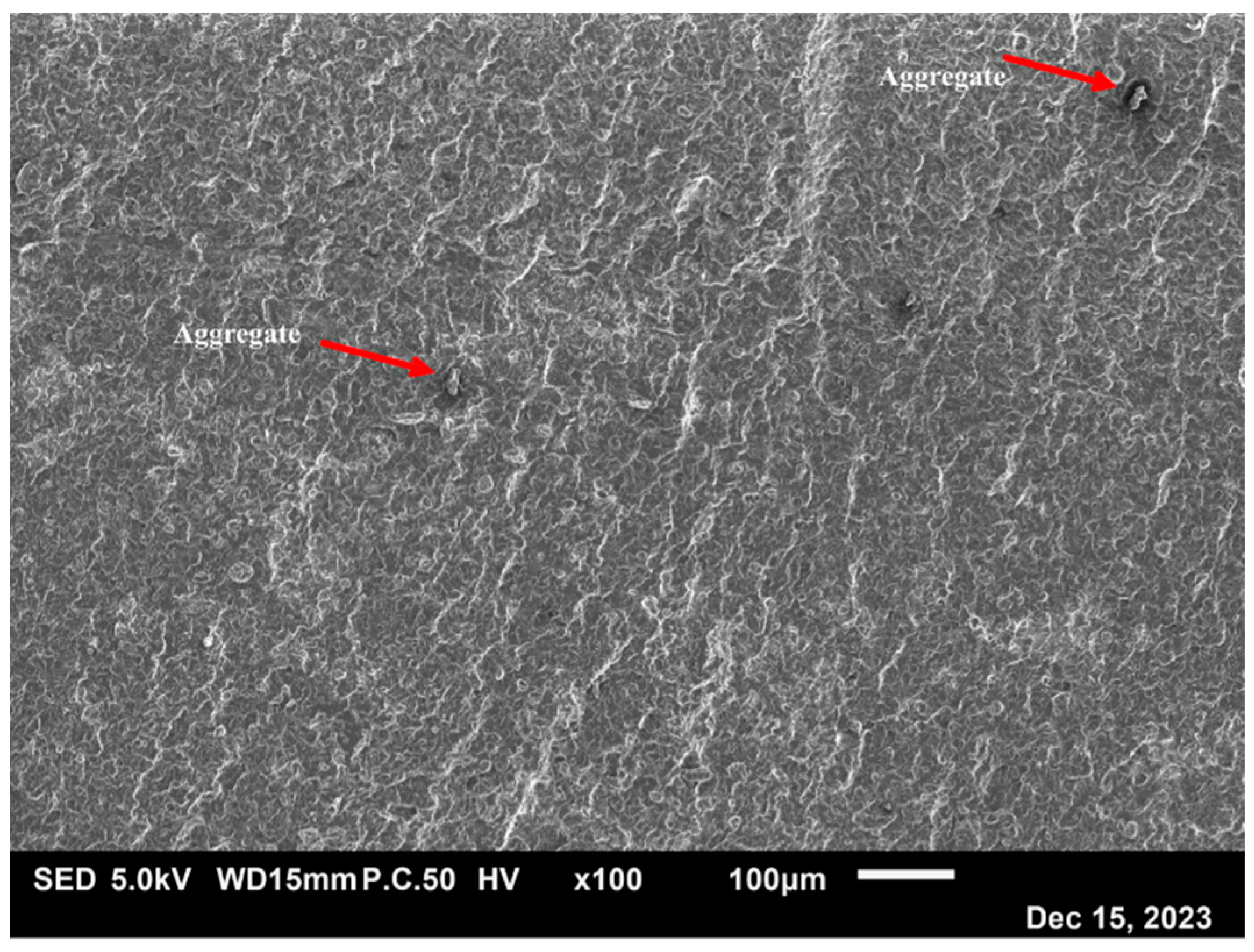
2.6.4. Scanning Electron Microscopy (SEM) Analysis
2.6.5. Statistical Analysis and Graphical Representation
3. Results and Discussions
3.1. Influence of Infill Ratio and Printing Temperature on 3D-Printed PLA
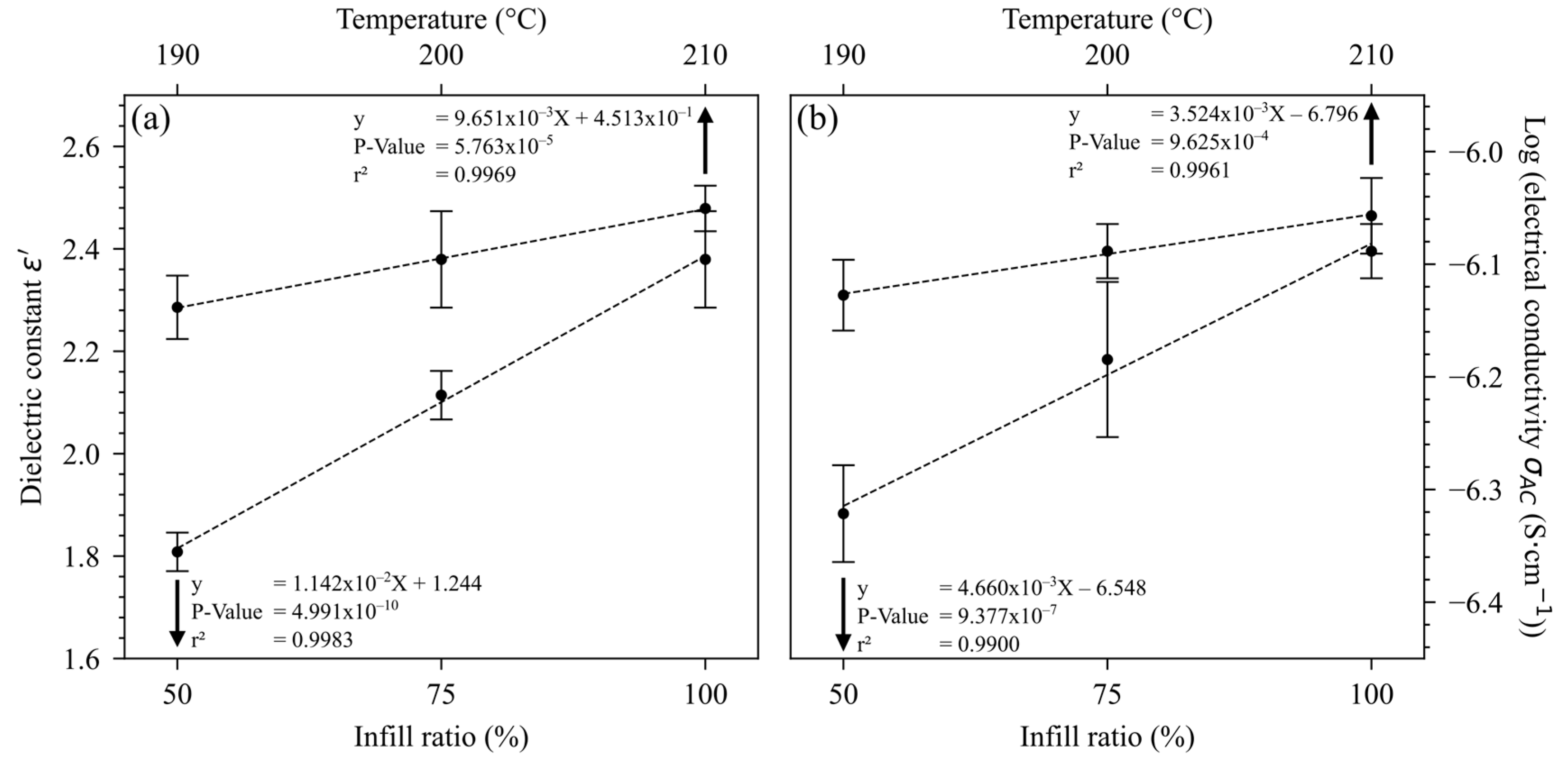
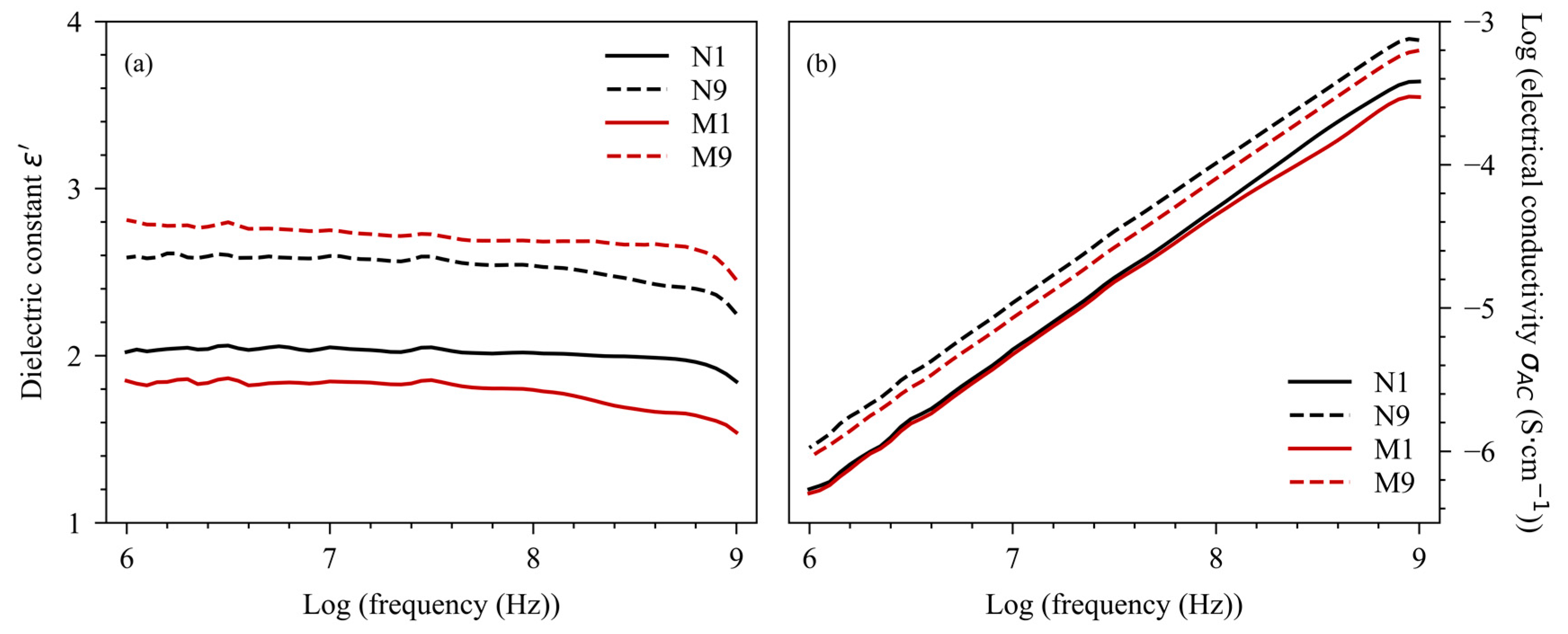
3.2. Dielectric Properties
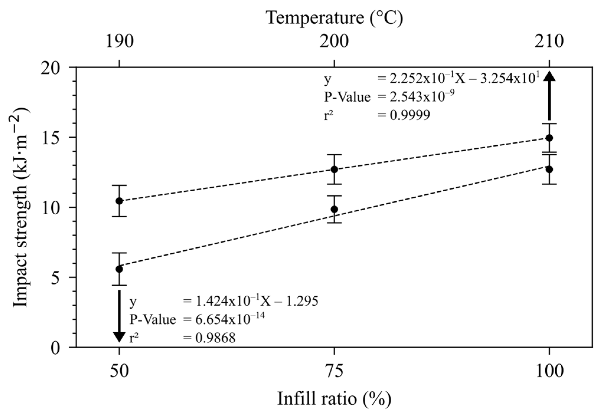
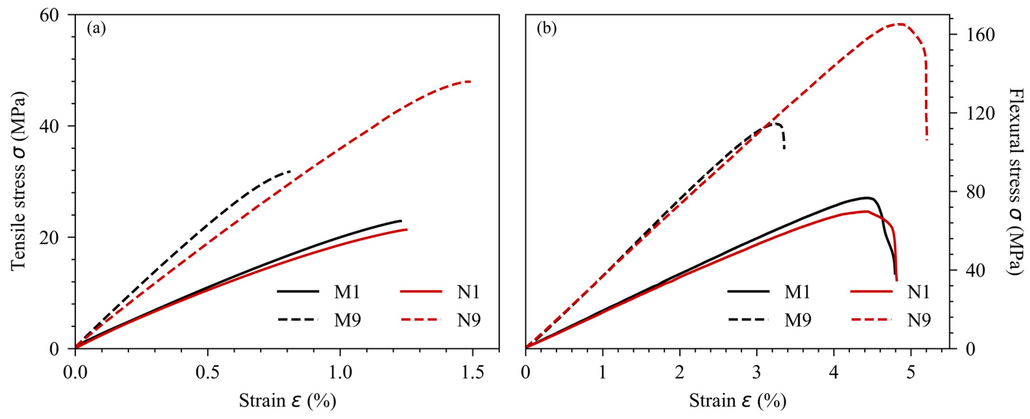
3.3. Mechanical Properties
4. Discussions
5. Conclusions
Supplementary Materials
Author Contributions
Funding
Data Availability Statement
Acknowledgments
Conflicts of Interest
References
- TechSci Research Electronic Materials Market Size and Trends 2028. Available online: https://www.techsciresearch.com/report/electronic-materials-market/18908.html (accessed on 17 January 2024).
- Nakatsuka, T. Polylactic Acid-Coated Cable. Fujikura Tech. Rev. 2011, 40, 39–46. [Google Scholar]
- Hegde, V.J.; Gallot-Lavallee, O.; Heux, L. Overview on Thermal and Electrical Properties of Biodegradable Polymers. In Proceedings of the 2015 IEEE 11th International Conference on the Properties and Applications of Dielectric Materials (ICPADM), Sydney, Australia, 19–22 July 2015; pp. 540–543. [Google Scholar]
- Lecoublet, M.; Ragoubi, M.; Kenfack, L.B.; Leblanc, N.; Koubaa, A. How Do 3D Printing Parameters Affect the Dielectric and Mechanical Performance of Polylactic Acid–Cellulose Acetate Polymer Blends? J. Compos. Sci. 2023, 7, 492. [Google Scholar] [CrossRef]
- Shi, S.; Jiang, Y.; Ren, H.; Deng, S.; Sun, J.; Cheng, F.; Jing, J.; Chen, Y. 3D-Printed Carbon-Based Conformal Electromagnetic Interference Shielding Module for Integrated Electronics. Nano-Micro Lett. 2024, 16, 85. [Google Scholar] [CrossRef] [PubMed]
- Barbosa, K.M.; Martinez, G.A.; Pereira, F.d.C.; Higuti, R.T.; Kitano, C.; Galeti, J.H. High Voltage Optical Sensor Insulation Using PLA (Polylactic Acid). In Proceedings of the 2018 13th IEEE International Conference on Industry Applications (INDUSCON), São Paulo, Brazil, 12–14 November 2018; pp. 1362–1367. [Google Scholar]
- Li, X.-R.; Guo, J.; Li, W.-D.; Zhang, L.-Y.; Wang, C.; Guo, B.-H.; Zhang, G.-J. Analysis of Morphology and Electrical Insulation of 3D Printing Parts. In Proceedings of the 2018 IEEE International Conference on High Voltage Engineering and Application (ICHVE), Athens, Greece, 10–13 September 2018; pp. 1–4. [Google Scholar]
- Yang, L.; Li, S.; Zhou, X.; Liu, J.; Li, Y.; Yang, M.; Yuan, Q.; Zhang, W. Effects of Carbon Nanotube on the Thermal, Mechanical, and Electrical Properties of PLA/CNT Printed Parts in the FDM Process. Synth. Met. 2019, 253, 122–130. [Google Scholar] [CrossRef]
- Kuzmanić, I.; Vujović, I.; Petković, M.; Šoda, J. Influence of 3D Printing Properties on Relative Dielectric Constant in PLA and ABS Materials. Prog. Addit. Manuf. 2023. [Google Scholar] [CrossRef] [PubMed]
- Zhang, S.; Arya, R.K.; Pandey, S.; Vardaxoglou, Y.; Whittow, W.; Mittra, R. 3D-Printed Planar Graded Index Lenses. IET Microw. Antennas Propag. 2016, 10, 1411–1419. [Google Scholar] [CrossRef]
- Akhoundi, B.; Behravesh, A.H. Effect of Filling Pattern on the Tensile and Flexural Mechanical Properties of FDM 3D Printed Products. Exp. Mech. 2019, 59, 883–897. [Google Scholar] [CrossRef]
- Alafaghani, A.; Qattawi, A.; Alrawi, B.; Guzman, A. Experimental Optimization of Fused Deposition Modelling Processing Parameters: A Design-for-Manufacturing Approach. Procedia Manuf. 2017, 10, 791–803. [Google Scholar] [CrossRef]
- Öteyaka, M.Ö.; Çakir, F.H.; Sofuoğlu, M.A. Effect of Infill Pattern and Ratio on the Flexural and Vibration Damping Characteristics of FDM Printed PLA Specimens. Mater. Today Commun. 2022, 33, 104912. [Google Scholar] [CrossRef]
- Samykano, M. Mechanical Property and Prediction Model for FDM-3D Printed Polylactic Acid (PLA). Arab. J. Sci. Eng. 2021, 46, 7875–7892. [Google Scholar] [CrossRef]
- Mathew, A.P.; Oksman, K.; Sain, M. Mechanical Properties of Biodegradable Composites from Poly Lactic Acid (PLA) and Microcrystalline Cellulose (MCC). J. Appl. Polym. Sci. 2005, 97, 2014–2025. [Google Scholar] [CrossRef]
- Badia, J.D.; Reig-Rodrigo, P.; Teruel-Juanes, R.; Kittikorn, T.; Strömberg, E.; Ek, M.; Karlsson, S.; Ribes-Greus, A. Effect of Sisal and Hydrothermal Ageing on the Dielectric Behaviour of Polylactide/Sisal Biocomposites. Compos. Sci. Technol. 2017, 149, 1–10. [Google Scholar] [CrossRef]
- Khouaja, A.; Koubaa, A.; Daly, H. Dielectric Properties and Thermal Stability of Cellulose High-Density Polyethylene Bio-Based Composites. Ind. Crops Prod. 2021, 171, 113928. [Google Scholar] [CrossRef]
- Larguech, S.; Triki, A.; Ramachandran, M.; Kallel, A. Dielectric Properties of Jute Fibers Reinforced Poly(Lactic Acid)/Poly(Butylene Succinate) Blend Matrix. J. Polym. Environ. 2021, 29, 1240–1256. [Google Scholar] [CrossRef]
- Dammak, Y. Propriétés mécaniques et stabilité dimensionnelle des biocomposites fabriqués par impression 3d par extrusion de filament; UQAT: Rouyn-Noranda, QC, Canada, 2022. [Google Scholar]
- Almeida, V.H.M.D.; Jesus, R.M.D.; Santana, G.M.; Khan, S.; Silva, E.F.M.S.; Cruz, I.S.D.; Santos, I.D.S.; Dos Anjos, P.N.M. The Development of Biocomposite Filaments for 3D Printing by Utilizing a Polylactic Acid (PLA) Polymer Matrix Reinforced with Cocoa Husk Cellulose Fibers. Polymers 2024, 16, 1757. [Google Scholar] [CrossRef]
- Patibandla, S.; Mian, A. Layer-to-Layer Physical Characteristics and Compression Behavior of 3D Printed Polymer Metastructures Fabricated Using Different Process Parameters. J. Elastomers Plast. 2021, 53, 386–401. [Google Scholar] [CrossRef]
- Pentek, A.; Nyitrai, M.; Schiffer, A.; Abraham, H.; Bene, M.; Molnar, E.; Told, R.; Maroti, P. The Effect of Printing Parameters on Electrical Conductivity and Mechanical Properties of PLA and ABS Based Carbon Composites in Additive Manufacturing of Upper Limb Prosthetics. Crystals 2020, 10, 398. [Google Scholar] [CrossRef]
- Fernandez-Vicente, M.; Calle, W.; Ferrandiz, S.; Conejero, A. Effect of Infill Parameters on Tensile Mechanical Behavior in Desktop 3D Printing. 3D Print. Addit. Manuf. 2016, 3, 183–192. [Google Scholar] [CrossRef]
- Gunasekaran, K.N.; Aravinth, V.; Muthu Kumaran, C.B.; Madhankumar, K.; Pradeep Kumar, S. Investigation of Mechanical Properties of PLA Printed Materials under Varying Infill Density. Mater. Today Proc. 2021, 45, 1849–1856. [Google Scholar] [CrossRef]
- Dharmalingam, G.; Arun Prasad, M.; Salunkhe, S. Investigation of Impact Strength at Different Infill Rates Biodegradable PLA Constituent through Fused Deposition Modeling. Mater. Today Proc. 2022, 62, 551–558. [Google Scholar] [CrossRef]
- Yakubu, A.; Abbas, Z.; Abdullahi, S. Mechanical, Dielectric and Shielding Performance of Rice Husk/Polycaprolactone Composites Enhanced via Rice Husk Particles Inclusion. Open Access Libr. J. 2020, 07, 1–12. [Google Scholar] [CrossRef]
- Wu, W.; Liu, T.; Zhang, D.; Sun, Q.; Cao, K.; Zha, J.; Lu, Y.; Wang, B.; Cao, X.; Feng, Y.; et al. Significantly Improved Dielectric Properties of Polylactide Nanocomposites via TiO2 Decorated Carbon Nanotubes. Composites Part A 2019, 127, 105650. [Google Scholar] [CrossRef]
- Salaeh, S.; Thitithammawong, A.; Salae, A. Highly Enhanced Electrical and Mechanical Properties of Methyl Methacrylate Modified Natural Rubber Filled with Multiwalled Carbon Nanotubes. Polym. Test. 2020, 85, 106417. [Google Scholar] [CrossRef]


| PLA (g) | MCC (g) | Masterbatch (g) (WNCC = 20%) | WMCC (%) | WNCC (%) | |
|---|---|---|---|---|---|
| PLA | 1200 | 0 | 0 | 0 | 0 |
| MCC-5 | 950 | 50 | 0 | 5 | 0 |
| MCC-10 | 900 | 100 | 0 | 10 | 0 |
| MCC-15 | 850 | 150 | 0 | 15 | 0 |
| NCC-1 | 950 | 0 | 50 | 0 | 1 |
| NCC-3 | 850 | 0 | 150 | 0 | 3 |
| NCC-5 | 750 | 0 | 250 | 0 | 5 |
| Parameters | Values |
|---|---|
| Nozzle temperature (°C) | 190–210 |
| Nozzle diameter (mm) | 0.8 |
| Nozzle speed (mm·s−1) | 40 |
| Bed temperature (°C) | 60 |
| Sample thickness (mm) | 3.2–4 |
| Layer thickness (mm) | 0.4 |
| Infill ratio (%) | 50–100 |
| Infill pattern | ±45° |
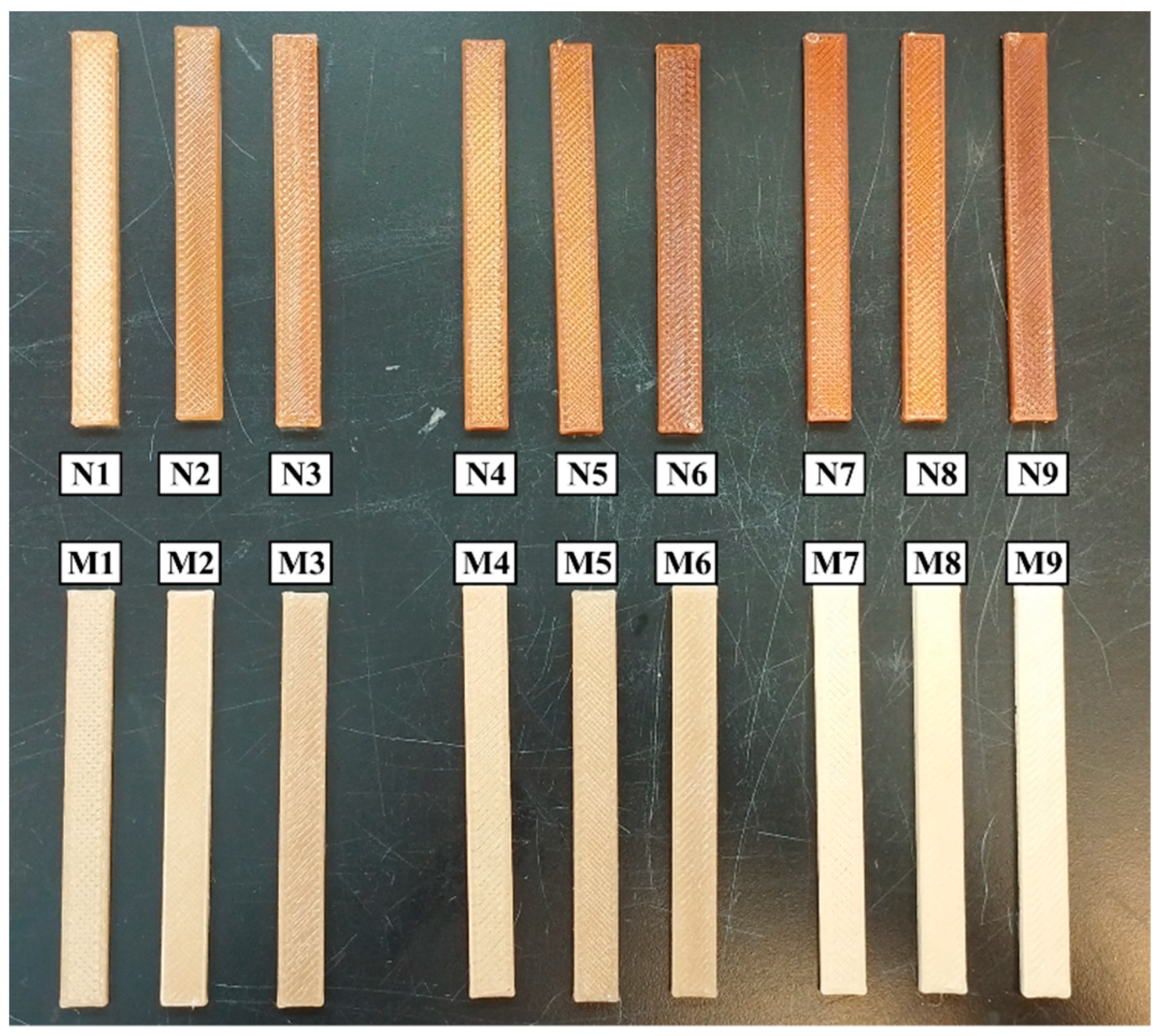
| Condition | Used Composite | Factor a Wf (%) | Factor b Infill Ratio (%) | Factor c Tprinting (°C) |
|---|---|---|---|---|
| M1 | MCC-5 | 5 | 50 | 190 |
| M2 | MCC-5 | 5 | 75 | 210 |
| M3 | MCC-5 | 5 | 100 | 200 |
| M4 | MCC-10 | 10 | 50 | 210 |
| M5 | MCC-10 | 10 | 75 | 200 |
| M6 | MCC-10 | 10 | 100 | 190 |
| M7 | MCC-15 | 15 | 50 | 200 |
| M8 | MCC-15 | 15 | 75 | 190 |
| M9 | MCC-15 | 15 | 100 | 210 |
| N1 | NCC-1 | 1 | 50 | 190 |
| N2 | NCC-1 | 1 | 75 | 210 |
| N3 | NCC-1 | 1 | 100 | 200 |
| N4 | NCC-3 | 3 | 50 | 210 |
| N5 | NCC-3 | 3 | 75 | 200 |
| N6 | NCC-3 | 3 | 100 | 190 |
| N7 | NCC-5 | 5 | 50 | 200 |
| N8 | NCC-5 | 5 | 75 | 190 |
| N9 | NCC-5 | 5 | 100 | 210 |
| Condition | Infill Ratio (%) | Tprinting (°C) |
|---|---|---|
| PLA-0 | 50 | 200 |
| PLA-1 | 75 | 200 |
| PLA-2 | 100 | 190 |
| PLA-3 | 100 | 200 |
| PLA-4 | 100 | 210 |
| MCC-Based Biocomposites | NCC-Based Bionanocomposites | |||
|---|---|---|---|---|
| Dielectric Constant ε’ | Electrical Conductivity σAC | Dielectric Constant ε’ | Electrical Conductivity σAC | |
| Wf | 5.2 ** | 2.9 n.s. | 3.8 * | 5.8 ** |
| Infill ratio | 46.5 *** | 33.1 *** | 39.9 *** | 34.2 *** |
| Tprinting | 1.8 n.s. | 3.2 * | 1.5 n.s. | 1.6 n.s. |
| MCC | NCC | ||||||
|---|---|---|---|---|---|---|---|
| Elastic Modulus | Maximal Stress | Elongation at Max Stress | Elastic Modulus | Maximal Stress | Elongation at Max Stress | ||
| Tensile results | Wf | 0.3 n.s | 7.4 ** | 79 *** | 0.5 n.s | 0.6 n.s | 0.7 n.s |
| Infill ratio | 110 *** | 9.3 *** | 0.1 n.s | 87 *** | 140 *** | 3.2 n.s | |
| Tprinting | 0.7 n.s | 1.7 n.s | 0.9 n.s | 0.4 n.s | 0.1 n.s | 0.3 n.s | |
| Flexural results | Wf | 1.4 n.s | 0.9 n.s | 39.3 *** | 2.5 n.s. | 2.2 n.s. | 2.4 n.s. |
| Infill ratio | 31.8 *** | 24.2 *** | 0.3 n.s | 18.2 *** | 22.1 *** | 4.4 * | |
| Tprinting | 2.4 n.s | 2.3 n.s | 0.3 n.s | 3.1 n.s. | 2.3 n.s. | 3.8 * | |
| MCC | NCC | |
|---|---|---|
| Impact strength | Impact strength | |
| Wf | 8.1 *** | 1.3 n.s. |
| Infill ratio | 7.7 *** | 261 *** |
| Tprinting | 2.4 n.s. | 2.2 n.s. |
| PLA-0 | PLA-3 | M7 | N7 | ||
|---|---|---|---|---|---|
| Used parameters | Wf | - | - | 15% MCC | 5% NCC |
| Infill ratio | 50 | 100 | 50 | 50 | |
| Tprinting | 200 | 200 | 200 | 200 | |
| BDS @ 1 MHz | ε’ | 1.81 ± 0.04 | 2.38 ± 0.09 | 2.19 ± 0.05 | 2.20 ± 0.03 |
| Log (σAC (S·cm−1)) | –6.32 ± 0.04 | –6.09 ± 0.02 | –6.19 ± 0.04 | –6.14 ± 0.02 | |
| Tensile | Modulus (GPa) | 1.72 ± 0.08 | 3.37 ± 0.03 | 2.73 ± 0.06 | 1.88 ± 0.09 |
| Max stress (MPa) | 24 ± 1 | 44 ± 3 | 19 ± 2 | 20 ± 1 | |
| Elongation (%) | 1.97 ± 0.08 | 1.45 ± 0.08 | 0.76 ± 0.01 | 1.29 ± 0.1 | |
| Flexural | Modulus (GPa) | 2.31 ± 0.02 | 3.68 ± 0.01 | 2.76 ± 0.16 | 1.94 ± 0.06 |
| Max stress (MPa) | 107 ± 3 | 171 ± 4 | 76 ± 3 | 73 ± 3 | |
| Elongation (%) | 5.34 ± 0.46 | 6.55 ± 0.04 | 3.06 ± 0.02 | 4.40 ± 0.33 | |
| Impact strength (kJ·m−2) | 5.59 ± 1,16 | 12.7 ± 1.1 | 3.83 ± 1.06 | 6.63 ± 0.99 | |
Disclaimer/Publisher’s Note: The statements, opinions and data contained in all publications are solely those of the individual author(s) and contributor(s) and not of MDPI and/or the editor(s). MDPI and/or the editor(s) disclaim responsibility for any injury to people or property resulting from any ideas, methods, instructions or products referred to in the content. |
© 2024 by the authors. Licensee MDPI, Basel, Switzerland. This article is an open access article distributed under the terms and conditions of the Creative Commons Attribution (CC BY) license (https://creativecommons.org/licenses/by/4.0/).
Share and Cite
Lecoublet, M.; Ragoubi, M.; Leblanc, N.; Koubaa, A. Optimizing the Dielectric and Mechanical Performance of 3D-Printed Cellulose-Based Biocomposites and Bionanocomposites through Factorial Design for Electrical Insulation Application. Polymers 2024, 16, 2117. https://doi.org/10.3390/polym16152117
Lecoublet M, Ragoubi M, Leblanc N, Koubaa A. Optimizing the Dielectric and Mechanical Performance of 3D-Printed Cellulose-Based Biocomposites and Bionanocomposites through Factorial Design for Electrical Insulation Application. Polymers. 2024; 16(15):2117. https://doi.org/10.3390/polym16152117
Chicago/Turabian StyleLecoublet, Morgan, Mohamed Ragoubi, Nathalie Leblanc, and Ahmed Koubaa. 2024. "Optimizing the Dielectric and Mechanical Performance of 3D-Printed Cellulose-Based Biocomposites and Bionanocomposites through Factorial Design for Electrical Insulation Application" Polymers 16, no. 15: 2117. https://doi.org/10.3390/polym16152117