
Exploring the Electrochemical Performance of Molybdenum Disulfide Nanoparticles Entrenched in Miscible Poly(methyl methacrylate)-Poly(lactic acid) Blends as Freestanding Electrodes for Supercapacitors
 , ,
, ,
Abstract
:1. Introduction
2. Experiments
2.1. Preparation of Membranes
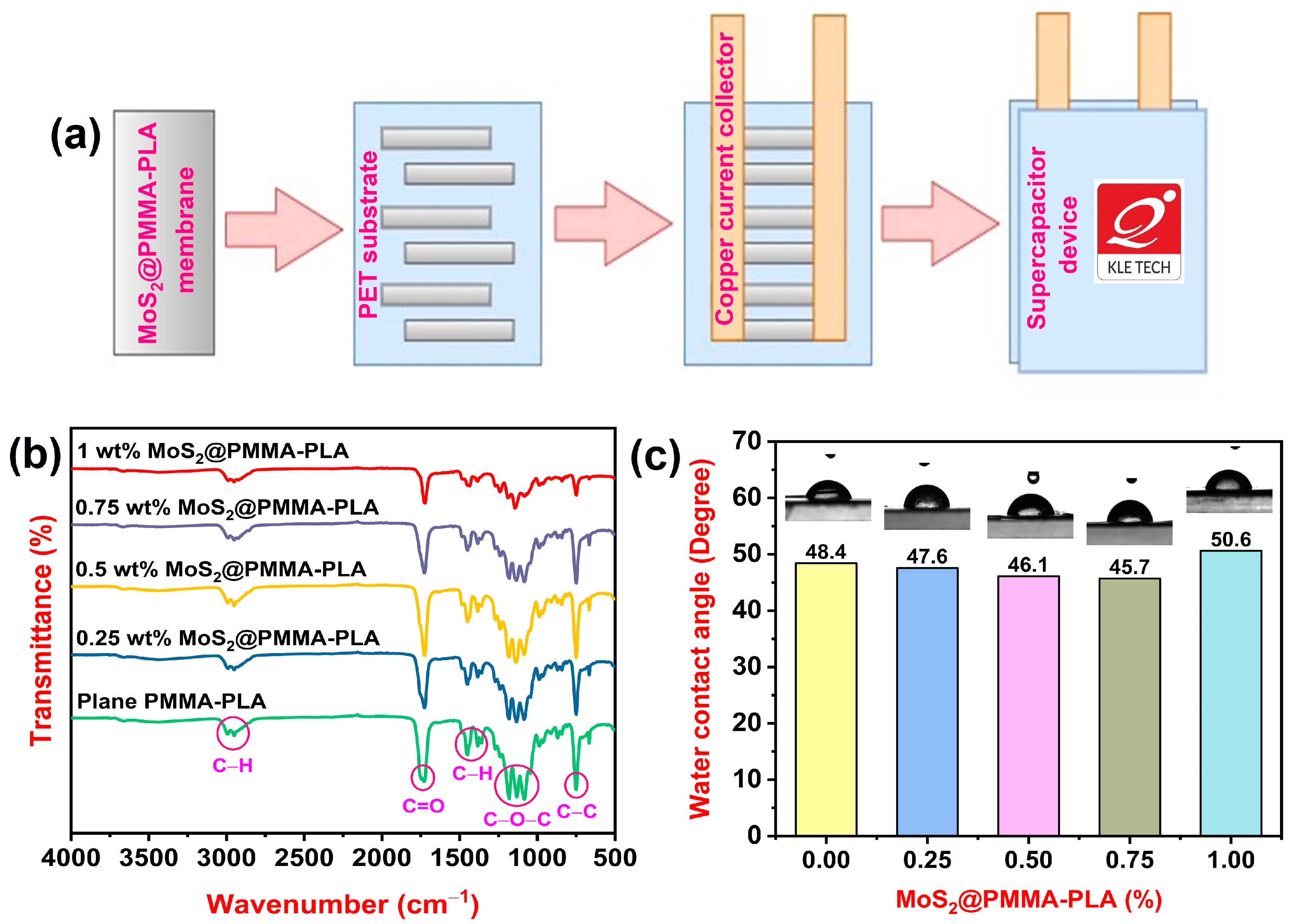
2.2. Development of a Supercapacitor Device
2.3. Physicochemical Measurements
2.4. Electrochemical Measurements
3. Results
3.1. FTIR Study
3.2. WCA Study
3.3. SEM Study
3.4. UTM Study
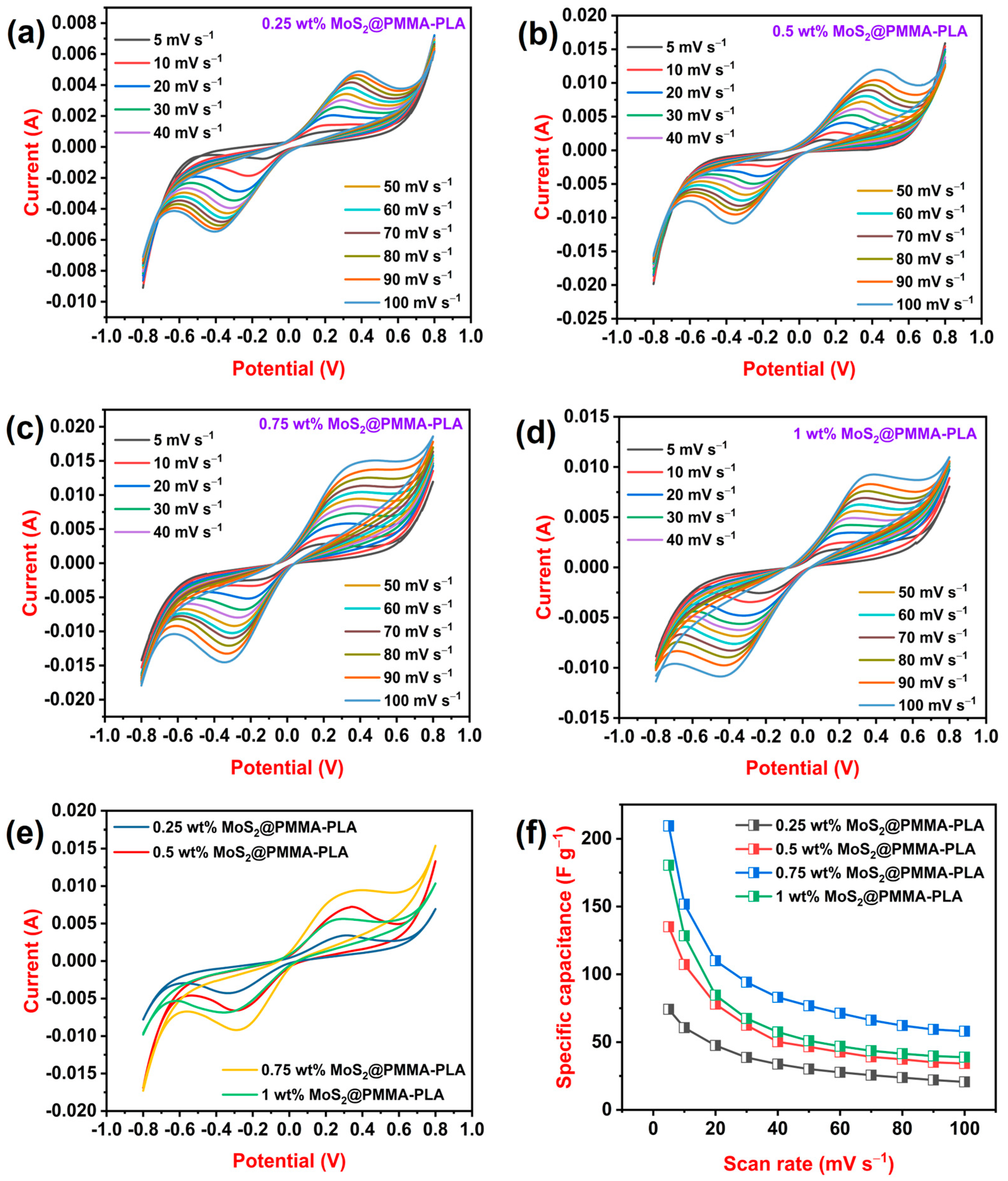
3.5. CV Study
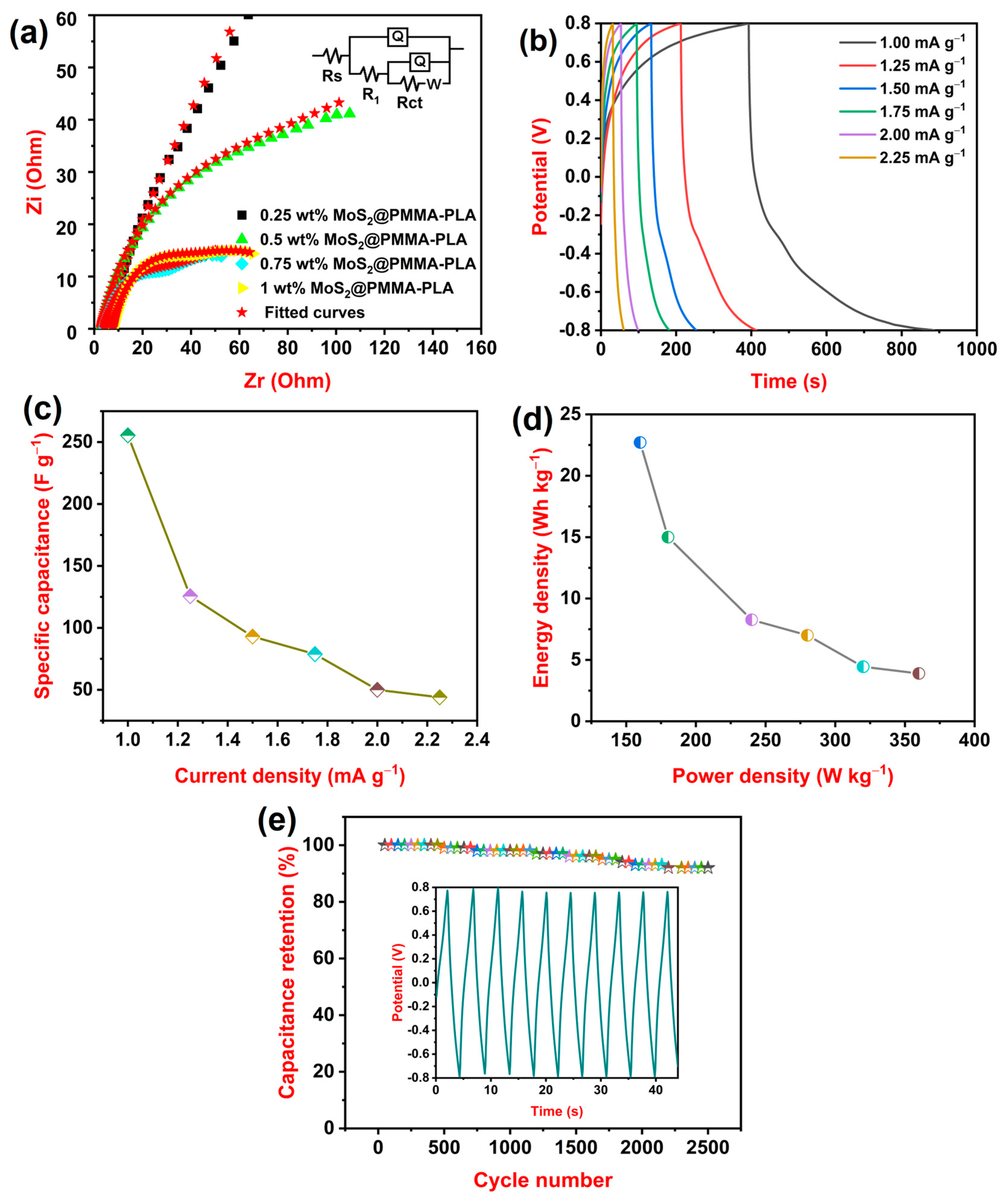
3.6. EIS Study
3.7. GCD Study
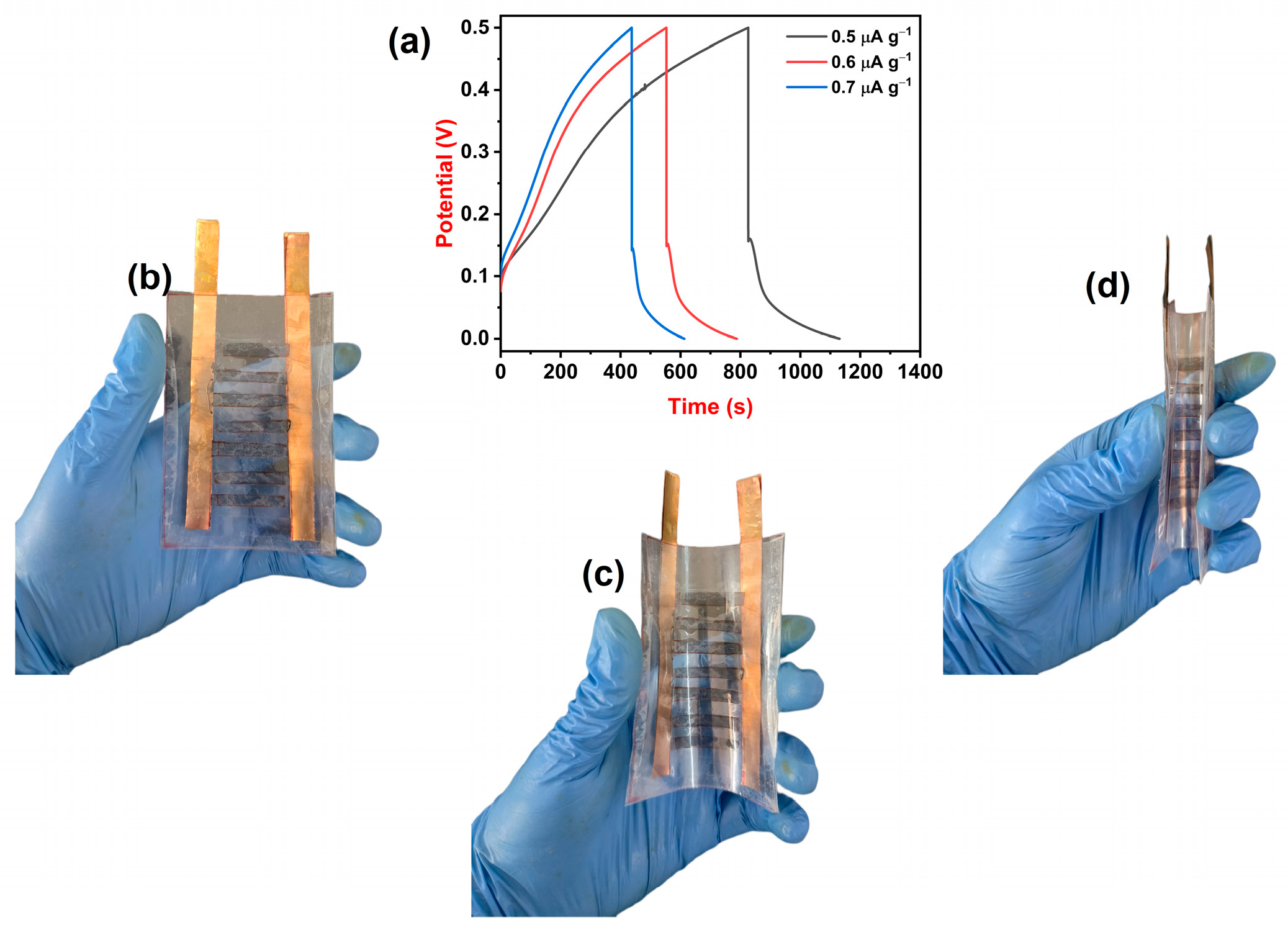
3.8. Supercapacitor Device Study
4. Conclusions
Author Contributions
Funding
Institutional Review Board Statement
Data Availability Statement
Acknowledgments
Conflicts of Interest
References
- Chikkatti, B.S.; Sajjan, A.M.; Kalahal, P.B.; Banapurmath, N.R.; Khan, T.M.Y.; Khadar, S.D.A.; Shamsudeen, S.M.; Raju, A.B. A Novel Poly(Vinyl Alcohol)–Tetraethylorthosilicate Hybrid Gel Electrolyte for Lead Storage Battery. Gels 2022, 8, 791. [Google Scholar] [CrossRef]
- Obeidat, A.M.; Gharaibeh, M.A.; Obaidat, M. Solid-State Supercapacitors with Ionic Liquid Gel Polymer Electrolyte and Polypyrrole Electrodes for Electrical Energy Storage. J. Energy Storage 2017, 13, 123–128. [Google Scholar] [CrossRef]
- Li, S.; Huang, D.; Zhang, B.; Xu, X.; Wang, M.; Yang, G.; Shen, Y. Flexible Supercapacitors Based on Bacterial Cellulose Paper Electrodes. Adv. Energy Mater. 2014, 4, 1301655. [Google Scholar] [CrossRef]
- Conte, M. Supercapacitors Technical Requirements Fornew Applications. Fuel Cells 2010, 10, 806–818. [Google Scholar] [CrossRef]
- Saidu, F.K.; Joseph, A.; Varghese, E.V.; Thomas, G.V. Characterization and Electrochemical Studies on Poly(1-Naphthylamine)-Graphene Oxide Nanocomposites Prepared by in Situ Chemical Oxidative Polymerization. J. Solid. State Electrochem. 2019, 23, 2897–2906. [Google Scholar] [CrossRef]
- Kumar, N.; Kim, S.B.; Lee, S.Y.; Park, S.J. Recent Advanced Supercapacitor: A Review of Storage Mechanisms, Electrode Materials, Modification, and Perspectives. Nanomaterials 2022, 12, 3708. [Google Scholar] [CrossRef]
- Lu, X.; Yu, M.; Wang, G.; Tong, Y.; Li, Y. Flexible Solid-State Supercapacitors: Design, Fabrication and Applications. Energy Environ. Sci. 2014, 7, 2160–2181. [Google Scholar] [CrossRef]
- Anakabe, J.; Zaldua Huici, A.M.; Eceiza, A.; Arbelaiz, A. Melt Blending of Polylactide and Poly(Methyl Methacrylate): Thermal and Mechanical Properties and Phase Morphology Characterization. J. Appl. Polym. Sci. 2015, 132, 42677. [Google Scholar] [CrossRef]
- Teoh, E.L.; Chow, W.S. Transparency, Ultraviolet Transmittance, and Miscibility of Poly(Lactic Acid)/Poly(Methyl Methacrylate) Blends. J. Elastomers Plast. 2018, 50, 596–610. [Google Scholar] [CrossRef]
- Nofar, M.; Salehiyan, R.; Ray, S.S. Influence of Nanoparticles and Their Selective Localization on the Structure and Properties of Polylactide-Based Blend Nanocomposites. Compos. B Eng. 2021, 215, 108845. [Google Scholar] [CrossRef]
- Paydayesh, A.; Azar, A.A.; Arani, A.J. A Change of Phase Morphology in Poly Lactic Acid/Poly Methyl Methacrylate Blends Induced by Graphene Nano Sheets. J. Macromol. Sci. Part B Phys. 2015, 54, 1466–1478. [Google Scholar] [CrossRef]
- Teoh, E.L.; Mariatti, M.; Chow, W.S. Thermal and Flame Resistant Properties of Poly(Lactic Acid)/Poly(Methyl Methacrylate) Blends Containing Halogen-Free Flame Retardant. Procedia Chem. 2016, 19, 795–802. [Google Scholar] [CrossRef]
- Anakabe, J.; Orue, A.; Zaldua Huici, A.M.; Eceiza, A.; Arbelaiz, A. Properties of PLA/PMMA Blends with High Polylactide Content Prepared by Reactive Mixing in Presence of Poly(Styrene-Co-Glycidyl Methacrylate) Copolymer. J. Appl. Polym. Sci. 2018, 135, 46825. [Google Scholar] [CrossRef]
- Zakariya’u, I.; Gultekin, B.; Singh, V.; Singh, P.K. Electrochemical Double-Layer Supercapacitor Using Poly(Methyl Methacrylate) Solid Polymer Electrolyte. High. Perform. Polym. 2020, 32, 201–207. [Google Scholar] [CrossRef]
- Pongpilaipruet, A.; Magaraphan, R. Influence of the Admicelled Poly(Methyl Methacrylate) on the Compatibility and Toughness of Poly(Lactic Acid). J. Mater. Res. 2018, 33, 662–673. [Google Scholar] [CrossRef]
- Hao, X.; Kaschta, J.; Pan, Y.; Liu, X.; Schubert, D.W. Intermolecular Cooperativity and Entanglement Network in a Miscible PLA/PMMA Blend in the Presence of Nanosilica. Polymer 2016, 82, 57–65. [Google Scholar] [CrossRef]
- Gonzalez-Garzon, M.; Shahbikian, S.; Huneault, M.A. Properties and Phase Structure of Melt-Processed PLA/PMMA Blends. J. Polym. Res. 2018, 25, 58. [Google Scholar] [CrossRef]
- Zhang, G.; Zhang, J.; Wang, S.; Shen, D. Miscibility and Phase Structure of Binary Blends of Polylactide and Poly(Methyl Methacrylate). J. Polym. Sci. Part B Polym. Phys. 2003, 41, 23–30. [Google Scholar] [CrossRef]
- Jiao, Y.; Hafez, A.M.; Cao, D.; Mukhopadhyay, A.; Ma, Y.; Zhu, H. Metallic MoS2 for High Performance Energy Storage and Energy Conversion. Small 2018, 14, 1800640. [Google Scholar] [CrossRef]
- Sun, T.; Li, Z.; Liu, X.; Ma, L.; Wang, J.; Yang, S. Facile Construction of 3D Graphene/MoS2 Composites as Advanced Electrode Materials for Supercapacitors. J. Power Sources 2016, 331, 180–188. [Google Scholar] [CrossRef]
- Ma, G.; Peng, H.; Mu, J.; Huang, H.; Zhou, X.; Lei, Z. In Situ Intercalative Polymerization of Pyrrole in Graphene Analogue of MoS2 as Advanced Electrode Material in Supercapacitor. J. Power Sources 2013, 229, 72–78. [Google Scholar] [CrossRef]
- Kim, S.; Konar, A.; Hwang, W.S.; Lee, J.H.; Lee, J.; Yang, J.; Jung, C.; Kim, H.; Yoo, J.B.; Choi, J.Y.; et al. High-Mobility and Low-Power Thin-Film Transistors Based on Multilayer MoS2 Crystals. Nat. Commun. 2012, 3, 1011. [Google Scholar] [CrossRef] [PubMed]
- Saha, D.; Kruse, P. Editors’ Choice—Review—Conductive Forms of MoS2 and Their Applications in Energy Storage and Conversion. J. Electrochem. Soc. 2020, 167, 126517. [Google Scholar] [CrossRef]
- Chen, P.; Liang, X.; Xu, Y.; Zhou, Y.; Nie, W. Enhanced Thermal and Mechanical Properties of PLA/MoS2 Nanocomposites Synthesized via the in-Situ Ring-Opening Polymerization. Appl. Surf. Sci. 2018, 440, 1143–1149. [Google Scholar] [CrossRef]
- Dai, J.; Lv, Y.; Zhang, J.; Zhang, D.; Xie, H.; Guo, C.; Zhu, A.; Xu, Y.; Fan, M.; Yuan, C.; et al. Effect of Morphology and Phase Engineering of MoS2 on Electrochemical Properties of Carbon Nanotube/Polyaniline@MoS2 Composites. J. Colloid. Interface Sci. 2021, 590, 591–600. [Google Scholar] [CrossRef] [PubMed]
- Mazuki, N.F.; Nagao, Y.; Kufian, M.Z.; Samsudin, A.S. The Influences of PLA into PMMA on Crystallinity and Thermal Properties Enhancement-Based Hybrid Polymer in Gel Properties. Mater. Today Proc. 2022, 49, 3105–3111. [Google Scholar] [CrossRef]
- Chikkatti, B.S.; Sajjan, A.M.; Banapurmath, N.R.; Bhutto, J.K.; Verma, R.; Yunus Khan, T.M. Fabrication of Flexible Films for Supercapacitors Using Halloysite Nano-Clay Incorporated Poly(Lactic Acid). Polymers 2023, 15, 4587. [Google Scholar] [CrossRef] [PubMed]
- Chikkatti, B.S.; Sajjan, A.M.; Kalahal, P.B.; Banapurmath, N.R.; Ayachit, N.H. Fabrication and Assessment of Poly(Lactic Acid)-Poly(4-Styrene Sulfonate) Flexible Membranes as Electrodes for Supercapacitors. J. Energy Storage 2023, 72, 108513. [Google Scholar] [CrossRef]
- Savaris, M.; Braga, G.L.; Dos Santos, V.; Carvalho, G.A.; Falavigna, A.; MacHado, D.C.; Viezzer, C.; Brandalise, R.N. Biocompatibility Assessment of Poly(Lactic Acid) Films after Sterilization with Ethylene Oxide in Histological Study in Vivo with Wistar Rats and Cellular Adhesion of Fibroblasts in Vitro. Int. J. Polym. Sci. 2017, 2017, 7158650. [Google Scholar] [CrossRef]
- Raheem, D.; Majid Nahi, Z. Polymethyl Methacrylate-Collagen-Magnesium Hydroxyapatite Bone Cement Preparation for Orthopedic Application. Chin. J. Biomed. Eng. 2020, 29, 18–23. [Google Scholar]
- Wei, S.Q.; Bai, Y.P.; Shao, L. A Novel Approach to Graft Acrylates onto Commercial Silicones for Release Film Fabrications by Two-Step Emulsion Synthesis. Eur. Polym. J. 2008, 44, 2728–2736. [Google Scholar] [CrossRef]
- Muller, O.; Guerchoux, M.; Braun, S.; Dandois, M.; Citak, H.; Jean, T.; Merlat, L. Polyvinylcarbazole: A New Polymer Host for Passive Optical Limiting. In Proceedings of the Nonlinear Optics and Its Applications, Strasbourg, France, 3 April–23 May 2022; Volume 12143, pp. 34–41. [Google Scholar] [CrossRef]
- Saraswathi, M.S.S.A.; Rana, D.; Vijayakumar, P.; Alwarappan, S.; Nagendran, A. Tailored PVDF Nanocomposite Membranes Using Exfoliated MoS2 Nanosheets for Improved Permeation and Antifouling Performance. New J. Chem. 2017, 41, 14315–14324. [Google Scholar] [CrossRef]
- Lalithambika, K.C.; Shanmugapriya, K.; Sriram, S. Photocatalytic Activity of MoS2 Nanoparticles: An Experimental and DFT Analysis. Appl. Phys. A Mater. Sci. Process 2019, 125, 817. [Google Scholar] [CrossRef]
- Charasseangpaisarn, T.; Wiwatwarrapan, C.; Thunyakitpisal, P.; Srimaneepong, V. Development of Poly(Methyl Methacrylate)/Poly(Lactic Acid) Blend as Sustainable Biomaterial for Dental Applications. Sci. Rep. 2023, 13, 16904. [Google Scholar] [CrossRef]
- Tian, H.; Wu, X.; Zhang, K. Polydopamine-Assisted Two-Dimensional Molybdenum Disulfide (MoS2)-Modified PES Tight Ultrafiltration Mixed-Matrix Membranes: Enhanced Dye Separation Performance. Membranes 2021, 11, 96. [Google Scholar] [CrossRef] [PubMed]
- Eksik, O.; Gao, J.; Shojaee, S.A.; Thomas, A.; Chow, P.; Bartolucci, S.F.; Lucca, D.A.; Koratkar, N. Epoxy Nanocomposites with Two-Dimensional Transition Metal Dichalcogenide Additives. ACS Nano 2014, 8, 5282–5289. [Google Scholar] [CrossRef]
- Wan, S.; Li, Y.; Peng, J.; Hu, H.; Cheng, Q.; Jiang, L. Synergistic Toughening of Graphene Oxide-Molybdenum Disulfide-Thermoplastic Polyurethane Ternary Artificial Nacre. ACS Nano 2015, 9, 708–714. [Google Scholar] [CrossRef] [PubMed]
- Wang, X.; Xing, W.; Feng, X.; Song, L.; Hu, Y. MoS2/Polymer Nanocomposites: Preparation, Properties, and Applications. Polym. Rev. 2017, 57, 440–466. [Google Scholar] [CrossRef]
- Chikkatti, B.S.; Sajjan, A.M.; Banapurmath, N.R.; Ayachit, N.H. Graphene-Doped Hydrogels Promoting Ionic Conductivity in Gel-Valve-Regulated Lead Acid Batteries. Langmuir 2023, 39, 17232–17239. [Google Scholar] [CrossRef]
- Huang, F.; Meng, R.; Sui, Y.; Wei, F.; Qi, J.; Meng, Q.; He, Y. One-Step Hydrothermal Synthesis of a CoS2@MoS2 Nanocomposite for High-Performance Supercapacitors. J. Alloys Compd. 2018, 742, 844–851. [Google Scholar] [CrossRef]
- Chikkatti, B.S.; Sajjan, A.M.; Kalahal, P.B.; Banapurmath, N.R. Insight into the Performance of Valve-Regulated Lead-Acid Battery Using Sodium Salt of Poly(4-Styrene Sulfonic Acid-Co-Maleic Acid)-Poly(Vinyl Alcohol) Gel Electrolyte. J. Energy Storage 2023, 72, 108261. [Google Scholar] [CrossRef]
- Chikkatti, B.S.; Sajjan, A.M.; Kalahal, P.B.; Banapurmath, N.R.; Angadi, A.R. Insight into the Performance of VRLA Battery Using PVA-TEOS Hybrid Gel Electrolytes with Titania Nanoparticles. J. Energy Storage 2023, 72, 108572. [Google Scholar] [CrossRef]
- Chikkatti, B.S.; Sajjan, A.M.; Banapurmath, N.R. The State of Understanding of the Electrochemical Behaviours of a Valve-Regulated Lead–Acid Battery Comprising Manganese Dioxide-Impregnated Gel Polymer Electrolyte. Mater. Adv. 2023, 4, 6192–6198. [Google Scholar] [CrossRef]
- Chikkatti, B.S.; Sajjan, A.M.; Banapurmath, N.R. Facilitating Ionic Conduction in the Valve-Regulated Lead Acid Battery by Poly(Vinyl Alcohol)-Halloysite Nano-Clay Gel Polymer Electrolyte. Energy Technol. 2024, 12, 2301265. [Google Scholar] [CrossRef]
- Masikhwa, T.M.; Madito, M.J.; Bello, A.; Dangbegnon, J.K.; Manyala, N. High Performance Asymmetric Supercapacitor Based on Molybdenum Disulphide/Graphene Foam and Activated Carbon from Expanded Graphite. J. Colloid. Interface Sci. 2017, 488, 155–165. [Google Scholar] [CrossRef]
- Pazhamalai, P.; Krishnamoorthy, K.; Manoharan, S.; Kim, S.J. High Energy Symmetric Supercapacitor Based on Mechanically Delaminated Few-Layered MoS2 Sheets in Organic Electrolyte. J. Alloys Compd. 2019, 771, 803–809. [Google Scholar] [CrossRef]
- Lv, T.; Yao, Y.; Li, N.; Chen, T. Highly Stretchable Supercapacitors Based on Aligned Carbon Nanotube/Molybdenum Disulfide Composites. Angew. Chem. 2016, 128, 9337–9341. [Google Scholar] [CrossRef]
- Moopri Singer Pandiyarajan, S.; Veerasubramani, G.K.; Bhattarai, R.M.; Gnanasekaran, G.; Kim, S.J.; Mok, Y.S. Designing an Interlayer-Widened MoS2-Packed Nitrogen-Rich Carbon Nanotube Core-Shell Structure for Redox-Mediated Quasi-Solid-State Supercapacitors. ACS Appl. Energy Mater. 2021, 4, 2218–2230. [Google Scholar] [CrossRef]
- Li, J.; Shi, Q.; Shao, Y.; Hou, C.; Li, Y.; Zhang, Q.; Wang, H. Cladding Nanostructured AgNWs-MoS2 Electrode Material for High-Rate and Long-Life Transparent in-Plane Micro-Supercapacitor. Energy Storage Mater. 2019, 16, 212–219. [Google Scholar] [CrossRef]
- Raman, V.; Rhee, D.; Selvaraj, A.R.; Kim, J.; Prabakar, K.; Kang, J.; Kim, H.K. High-Performance Flexible Transparent Micro-Supercapacitors from Nanocomposite Electrodes Encapsulated with Solution Processed MoS2 Nanosheets. Sci. Technol. Adv. Mater. 2021, 22, 875–884. [Google Scholar] [CrossRef]


| Membranes | Tensile Strength (MPa) | Young’s Modulus (MPa) | Elongation at Break (%) |
|---|---|---|---|
| Plain PMMA-PLA | 11.1 | 2130 | 1.07 |
| 0.25 wt% MoS2@PMMA-PLA | 12.3 | 3761 | 0.628 |
| 0.5 wt% MoS2@PMMA-PLA | 18.5 | 4316 | 0.519 |
| 0.75 wt% MoS2@PMMA-PLA | 20.2 | 4463 | 0.338 |
| 1 wt% MoS2@PMMA-PLA | 13.9 | 4167 | 0.426 |
| Membranes | Rs (Ω) | Q (S-sn) | n | R1 (Ω) | Q (S-sn) | n | Rct (Ω) | W (S-s5) |
|---|---|---|---|---|---|---|---|---|
| 0.25 wt% MoS2@PMMA-PLA | 7.404 | 0.00146 | 0.7 | 0.082 | 0.000103 | 0.8 | 489 | 0.000816 |
| 0.5 wt% MoS2@PMMA-PLA | 6.329 | 0.00311 | 0.8 | 0.040 | 0.000177 | 0.9 | 317 | 0.000736 |
| 0.75 wt% MoS2@PMMA-PLA | 2.852 | 0.00593 | 0.8 | 0.020 | 0.000242 | 0.8 | 106 | 0.000172 |
| 1 wt% MoS2@PMMA-PLA | 4.371 | 0.00563 | 0.7 | 0.032 | 0.000178 | 0.8 | 137 | 0.000359 |
| Sl. no | Composition | Method | Electrolyte | Capacitance | Energy Density | Power Density | Capacitance Retention | References |
|---|---|---|---|---|---|---|---|---|
| 1 | MoS2/GF//AEG | Hydrothermal | 3 M KCl | 59 F g−1 @ 1 Ag−1 | 16 Wh kg−1 | 758 W kg−1 | 95 %@ 2000 cycles | [46] |
| 2 | Few layered MoS2 | Ball milling | Organic | 14.7 F g−1 @ 0.75 Ag−1 | 18.43 Wh kg−1 | 1125 W kg−1 | 91.2% @ 5000 cycles | [47] |
| 3 | CNT/MoS2 | Chemical vapor deposition | PVA/H3PO4 | 13.16 F cm−3 @ 0.1 mA | 1.05 mWh cm−3 | 0.46 Wcm−3 | 98 %@ 10,000 cycles | [48] |
| 4 | MoS2-CNT-PPY | Hydrothermal | PVA/H2SO4 /Na2MoO4 | 37.4 F g−1 @ 1 mA | 3.2 Wh kg−1 | 625 W kg−1 | 94.5% @ 5000 | [49] |
| 5 | AgNW-MoS2 | Laser writing | PVA-H2SO4 | 27.6 mF cm−2 @ 0.2 V s−1 | 2.453 mWh cm−2 | 1.472 mW cm−2 | 96.4 %@ 10,000 cycles | [50] |
| 6 | MoS2-PEDOT:PSS | Spin coating | 3 M KOH | 89.44 mF cm−2 @ 6 mA cm−2 | 12.42 mWh cm−2 | 6043 mW cm−2 | - | [51] |
| 7 | MoS2@PMMA-PLA | Solution casting | 1 M H2SO4 | 255.5 F g−1 @ 1.00 mA g−1 | 22.7 Wh kg−1 | 360 W kg−1 | 92 %@ 2500 cycles | This work |
Disclaimer/Publisher’s Note: The statements, opinions and data contained in all publications are solely those of the individual author(s) and contributor(s) and not of MDPI and/or the editor(s). MDPI and/or the editor(s) disclaim responsibility for any injury to people or property resulting from any ideas, methods, instructions or products referred to in the content. |
© 2024 by the authors. Licensee MDPI, Basel, Switzerland. This article is an open access article distributed under the terms and conditions of the Creative Commons Attribution (CC BY) license (https://creativecommons.org/licenses/by/4.0/).
Share and Cite
Chikkatti, B.S.; Kanaki, L.S.; Sajjan, A.M.; Banapurmath, N.R.; Umarfarooq, M.A.; Hosmath, R.S.; Badruddin, I.A.; Arabi, A.I.A.; Kamangar, S. Exploring the Electrochemical Performance of Molybdenum Disulfide Nanoparticles Entrenched in Miscible Poly(methyl methacrylate)-Poly(lactic acid) Blends as Freestanding Electrodes for Supercapacitors. Polymers 2024, 16, 2184. https://doi.org/10.3390/polym16152184
Chikkatti BS, Kanaki LS, Sajjan AM, Banapurmath NR, Umarfarooq MA, Hosmath RS, Badruddin IA, Arabi AIA, Kamangar S. Exploring the Electrochemical Performance of Molybdenum Disulfide Nanoparticles Entrenched in Miscible Poly(methyl methacrylate)-Poly(lactic acid) Blends as Freestanding Electrodes for Supercapacitors. Polymers. 2024; 16(15):2184. https://doi.org/10.3390/polym16152184
Chicago/Turabian StyleChikkatti, Bipin S., Lata S. Kanaki, Ashok M. Sajjan, Nagaraj R. Banapurmath, M. A. Umarfarooq, R. S. Hosmath, Irfan Anjum Badruddin, Amir Ibrahim Ali Arabi, and Sarfaraz Kamangar. 2024. "Exploring the Electrochemical Performance of Molybdenum Disulfide Nanoparticles Entrenched in Miscible Poly(methyl methacrylate)-Poly(lactic acid) Blends as Freestanding Electrodes for Supercapacitors" Polymers 16, no. 15: 2184. https://doi.org/10.3390/polym16152184