


Harnessing the Potential of Hollow Graphitic Carbon Nanocages for Enhanced Methanol Oxidation Using PtRu Nanoparticles

 , ,
, ,  ,
,
Abstract
1. Introduction
2. Materials and Methods
2.1. Materials and Chemicals
2.2. Structural Characterizations
- d = estimated crystallite size,
- K = is a dimensionless shape factor, with a value close to unity. The shape factor has a typical value of about 0.94,
- λ = X-ray wavelength (constant value of 0.154)
- B = line broadening at half the maximum intensity (FWHM), after subtracting the instrumental line broadening (in radians), and
- θ = Bragg’s angle.
2.3. Preparation of Hollow Carbon Nanocages (CNCs) from Polypyrrole (PPy) and Polyaniline (PANI)
2.4. Preparation of CNCs Supported PtRu Nanoparticles (PtRu/CNC) and Commercial Carbon Black Supported PtRu Nanoparticles (PtRu/CB)
- (i)
- The alcohol reduction methods is relatively simple and the equipment/reagents needed are readily available. Normally, it operates under mild reaction conditions, including ambient temperature and pressure. This mildness is advantageous as it simplifies the experimental setup and reduces the energy requirements for synthesis.
- (ii)
- It is environmentally friendly compared to other synthesis methods. Alcohol solvents, such as ethylene glycol or isopropanol, are relatively non-toxic and reduce the generation of hazardous waste.
- (iii)
- It tends to produce high purity of PtRu nanoparticles with good crystallinity. The alcohol solvents helps in reducing impurities and preventing the formation of unwanted byproducts. The resulting PtRu nanoparticles exhibit well-defined crystal structures, which can enhance their electrocatalytic properties.
- (iv)
- It promotes the formation of homogeneous and uniform distribution of Pt and Ru atoms over supporting material. This is attributed to the reduction mechanism and the coordination ability of alcohol molecules, which facilitate the mixing of Pt and Ru at the atomic level. The resulting homogeneous structure strongly influences the catalytic performance and stability of the PtRu catalyst.
2.5. Electrochemical Performance of PtRu Electrocatalysts
2.6. Preparation of Membrane Electrode Assembly (MEA)
2.7. DMFC Single Cell Test
3. Results and Discussion
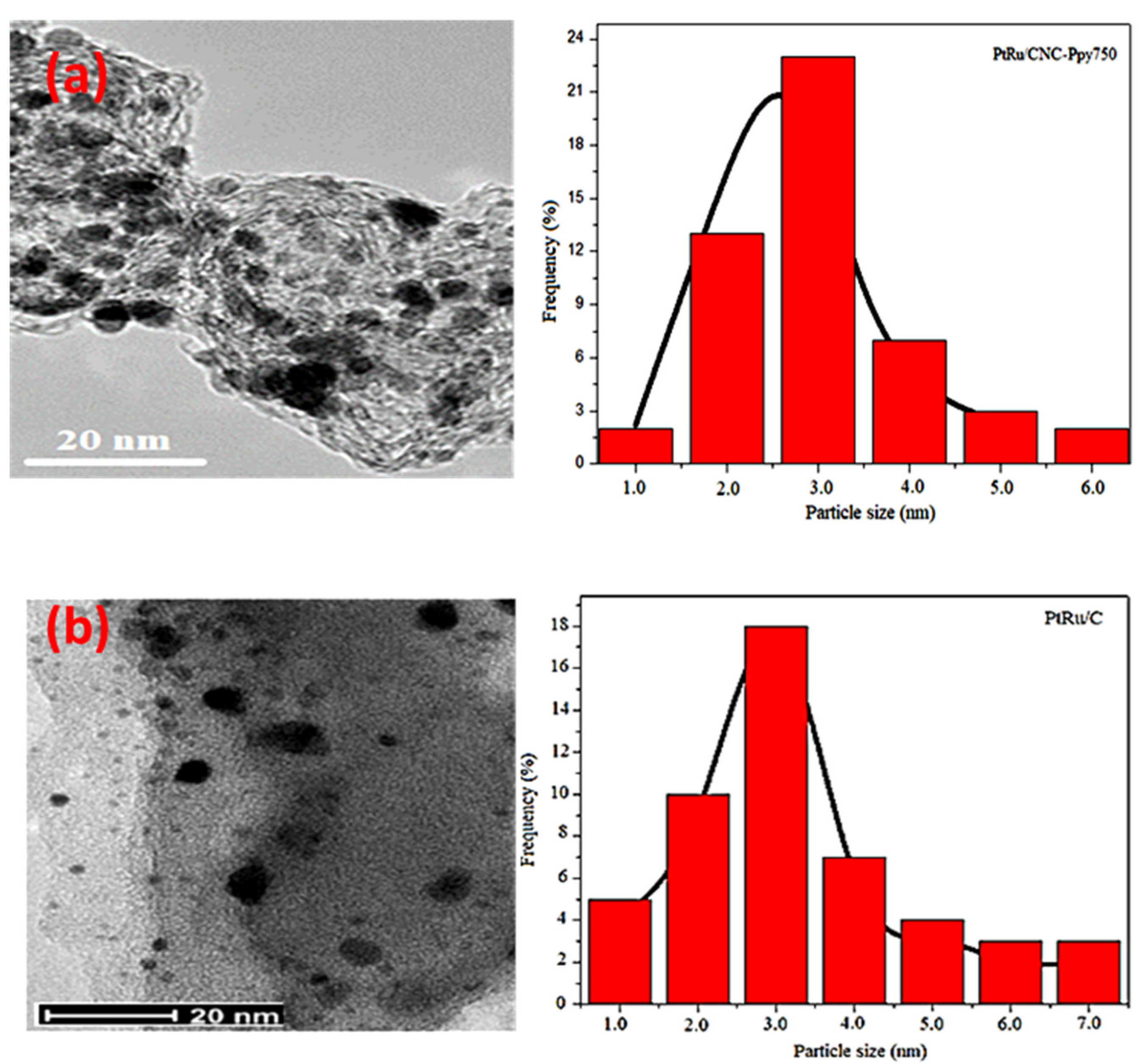
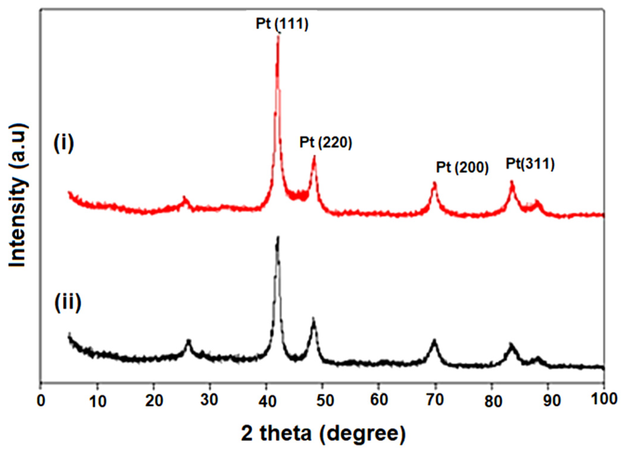
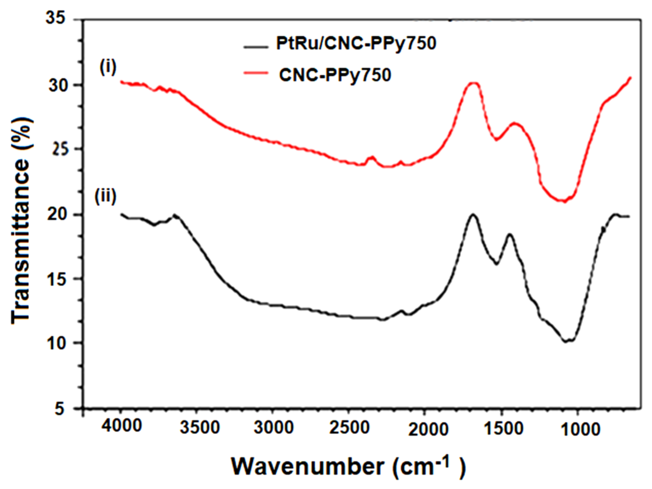
3.1. Structural Characterization of CNC Supports and Their Electrocatalysts
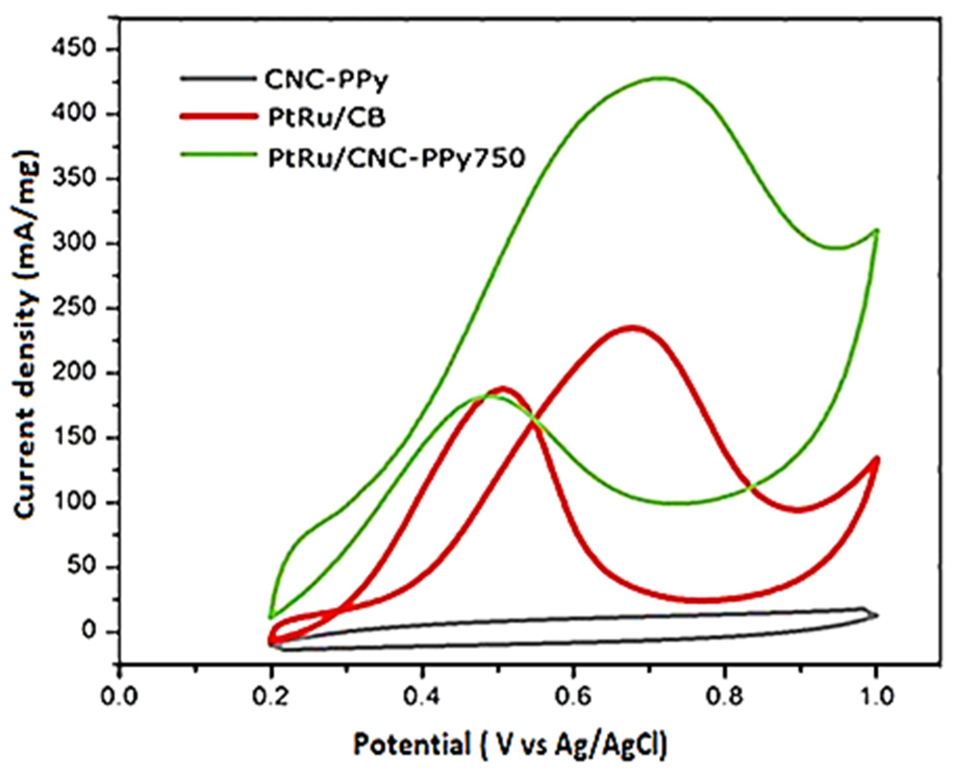
3.2. Electrochemical Performance of PtRu/CNC-Ppy750 Electrocatalyst
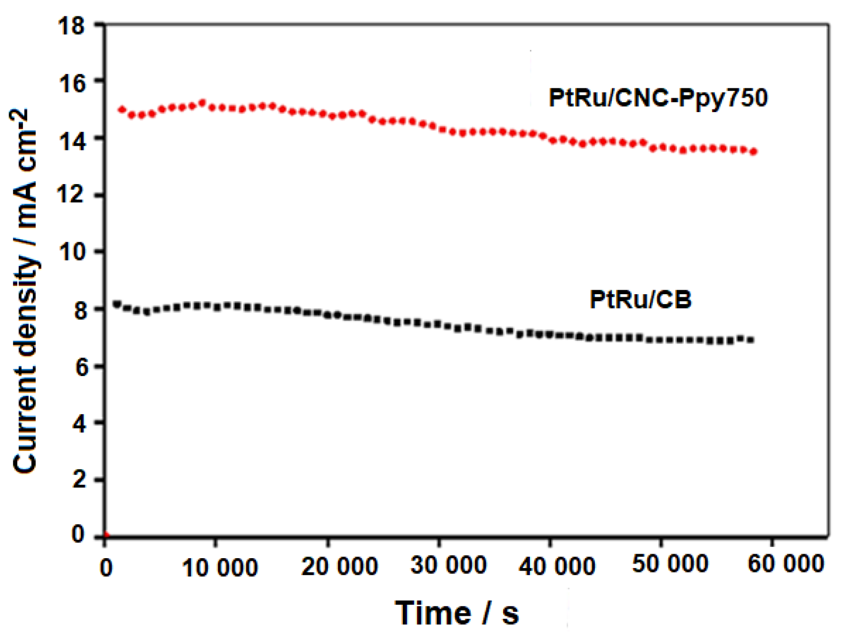
3.3. DMFC Performance of PtRu/CNC-Ppy750 Electrocatalyst
4. Conclusions
Author Contributions
Funding
Institutional Review Board Statement
Data Availability Statement
Conflicts of Interest
References
- Ramli, Z.A.C.; Shaari, N.; Saharuddin, T.S.T. Progress and Major BARRIERS of Nanocatalyst Development in Direct Methanol Fuel Cell: A Review. Int. J. Hydrogen Energy 2022, 47, 22114–22146. [Google Scholar] [CrossRef]
- de Sá, M.H.; Moreira, C.S.; Pinto, A.M.F.R.; Oliveira, V.B. Recent Advances in the Development of Nanocatalysts for Direct Methanol Fuel Cells. Energies 2022, 15, 6335. [Google Scholar] [CrossRef]
- Xia, Z.; Zhang, X.; Sun, H.; Wang, S.; Sun, G. Recent Advances in Multi-Scale Design and Construction of Materials for Direct Methanol Fuel Cells. Nano Energy 2019, 65, 104048. [Google Scholar] [CrossRef]
- Kumar, P.; Dutta, K.; Kundu, P.P. Enhanced Performance of Direct Methanol Fuel Cells: A Study on the Combined Effect of Various Supporting Electrolytes, Fl Ow Channel Designs and Operating Temperatures. Int. J. Energy Res. 2014, 38, 41–50. [Google Scholar] [CrossRef]
- Kumar, P.; Dutta, K.; Das, S.; Kundu, P.P. An Overview of Unsolved de Fi Ciencies of Direct Methanol Fuel Cell Technology: Factors and Parameters Affecting Its Widespread Use. Int. J. Energy Res. 2014, 38, 1367–1390. [Google Scholar] [CrossRef]
- Ong, B.C.; Kamarudin, S.K.; Basri, S. Direct Liquid Fuel Cells: A Review. Int. J. Hydrogen Energy 2017, 42, 10142–10157. [Google Scholar] [CrossRef]
- Shaari, N.; Kamarudin, S.K.; Bahru, R.; Osman, S.H.; Md Ishak, N.A.I. Progress and Challenges: Review for Direct Liquid Fuel Cell. Int. J. Energy Res. 2021, 45, 6644–6688. [Google Scholar] [CrossRef]
- Bai, X.; Geng, J.; Zhao, S.; Li, H.; Li, F. Tunable Hollow Pt@Ru Dodecahedra via Galvanic Replacement for Efficient Methanol Oxidation. ACS Appl. Mater. Interfaces 2020, 12, 23046–23050. [Google Scholar] [CrossRef] [PubMed]
- Osman, S.H.; Kamarudin, S.K.; Basri, S.; Karim, A.N. Three-Dimensional Graphene Aerogel Supported on Efficient Anode Electrocatalyst for Methanol Electrooxidation in Acid Media. Catalysts 2023, 13, 879. [Google Scholar] [CrossRef]
- Musa, M.T.; Shaari, N.; Raduwan, N.F.; Kamarudin, S.K.; Wong, W.Y. Alginate/PVA Polymer Electrolyte Membrane Modified by Hydrophilic Montmorillonite for Structure and Selectivity Enhancement for DMFC Application. Polymers 2023, 15, 2590. [Google Scholar] [CrossRef] [PubMed]
- Hung, C.T.; Liou, Z.H.; Veerakumar, P.; Wu, P.H.; Liu, T.C.; Liu, S. Bin Ordered Mesoporous Carbon Supported Bifunctional PtM (M = Ru, Fe, Mo) Electrocatalysts for a Fuel Cell Anode. Cuihua Xuebao/Chin. J. Catal. 2016, 37, 43–53. [Google Scholar] [CrossRef]
- Calderón, J.C.; García, G.; Querejeta, A.; Alcaide, F.; Calvillo, L.; Lázaro, M.J.; Rodríguez, J.L.; Pastor, E. Electrochimica Acta Carbon Monoxide and Methanol Oxidations on Carbon Nano Fi Bers Supported Pt–Ru Electrodes at Different Temperatures. Electrochim. Acta 2015, 186, 359–368. [Google Scholar] [CrossRef]
- Bong, S.; Han, D. Mesopore-Controllable Carbon Aerogel and Their Highly Loaded PtRu Anode Electrocatalyst for DMFC. Electroanalysis 2019, 32, 104–111. [Google Scholar] [CrossRef]
- Tian, X.; Wang, L.; Deng, P.; Chen, Y.; Xia, B. Research Advances in Unsupported Pt-Based Catalysts for Electrochemical Methanol Oxidation. J. Energy Chem. 2017, 26, 1067–1076. [Google Scholar] [CrossRef]
- Rodriguez, J.R.; Fuentes-Moyado, S.; Zepeda, T.A.; Díaz de León, J.N.; Cruz-Reyes, J.; Oropeza-Guzman, M.T.; Berhault, G.; Alonso-Núñez, G. Methanol Electro-Oxidation with Alloy Nanoparticles of Pt10−x–Fex Supported on CNTs. Fuel 2016, 182, 1–7. [Google Scholar] [CrossRef]
- Wu, B.; Li, Y.; Wang, C.; Xue, D.; Xiao, J. ScienceDirect High Aqueous Solubility of Carboxylated-Carbon Nanotubes as Support for PtRu Nanoparticles: Enhanced Dispersion and Electrocatalytic Performance. Int. J. Hydrogen Energy 2014, 9, 3–10. [Google Scholar]
- Calderón, J.C.; García, G.; Calvillo, L.; Rodríguez, J.L.; Lázaro, M.J.; Pastor, E. Electrochemical Oxidation of CO and Methanol on Pt–Ru Catalysts Supported on Carbon Nanofibers: The Influence of Synthesis Method. Appl. Catal. B Environ. 2015, 165, 676–686. [Google Scholar] [CrossRef]
- Tsukagoshi, Y.; Ishitobi, H.; Nakagawa, N. Improved Performance of Direct Methanol Fuel Cells with the Porous Catalyst Layer Using Highly-Active Nanofiber Catalyst. Carbon Resour. Convers. 2018, 1, 61–72. [Google Scholar] [CrossRef]
- Han, J.; Yang, L.; Yang, L.; Jiang, W.; Luo, X. ScienceDirect PtRu Nanoalloys Loaded on Graphene and TiO2 Nanotubes Co-Modified Ti Wire as an Active and Stable Methanol Oxidation Electrocatalyst. Int. J. Hydrogen Energy 2018, 3, 1–9. [Google Scholar]
- Rethinasabapathy, M.; Kang, S.-M.; Haldorai, Y.; Jonna, N.; Jankiraman, M.; Lee, G.-W.; Jang, S.-C.; Natesan, B.; Roh, C.; Huh, Y.S. Quaternary PtRuFeCo Nanoparticles Supported N-Doped Graphene as an Efficient Bifunctional Electrocatalyst for Low-Temperature Fuel Cells. J. Ind. Eng. Chem. 2018, 69, 285–294. [Google Scholar] [CrossRef]
- Zhao, Y.; Fan, L.; Ren, J.; Hong, B. Electrodeposition of Pt–Ru and Pt–Ru–Ni Nanoclusters on Multi-Walled Carbon Nanotubes for Direct Methanol Fuel Cell. Int. J. Hydrogen Energy 2014, 39, 4544–4557. [Google Scholar] [CrossRef]
- Nouralishahi, A.; Rashidi, A.M.; Mortazavi, Y.; Khodadadi, A.A.; Choolaei, M. Enhanced Methanol Electro-Oxidation Reaction on Pt-CoOxMWCNTs Hybrid Electro-Catalyst. Appl. Surf. Sci. 2015, 335, 55–64. [Google Scholar] [CrossRef]
- Electro-oxidation, M. Nitrogen Doped Ordered Mesoporous Carbon as Support of PtRu Nanoparticles For. Energies 2018, 11, 831. [Google Scholar] [CrossRef]
- Wu, X.; Zhuang, W.; Lu, L.; Li, L.; Zhu, J.; Mu, L.; Li, W.; Zhu, Y.; Lu, X. Excellent Performance of Pt-C/TiO2 for Methanol Oxidation: Contribution of Mesopores and Partially Coated Carbon. Appl. Surf. Sci. 2017, 426, 890–896. [Google Scholar] [CrossRef]
- Liu, W.; Qin, X.; Zhang, X.; Shao, Z.; Yi, B. Wormholelike Mesoporous Carbon Supported PtRu Catalysts toward Methanol Electrooxidation. J. Energy Chem. 2016, 26, 200–206. [Google Scholar] [CrossRef]
- Dubau, L.; Castanheira, L.; Maillard, F.; Chatenet, M.; Lottin, O.; Maranzana, G.; Dillet, J.; Lamibrac, A.; Perrin, J.C.; Moukheiber, E.; et al. A Review of PEM Fuel Cell Durability: Materials Degradation, Local Heterogeneities of Aging and Possible Mitigation Strategies. Wiley Interdiscip. Rev. Energy Environ. 2014, 3, 540–560. [Google Scholar] [CrossRef]
- Tripachev, O.V.; Panchenko, N.V.; Korchagin, O.V.; Radina, M.V.; Dolgopolov, S.V.; Grafov, O.Y.; Bogdanovskaya, V.A. A Novel Pt/MoS2/CNT Composite Catalyst for the Positive Electrode of a Li-O2 Battery. J. Electroanal. Chem. 2021, 897, 115554. [Google Scholar] [CrossRef]
- Gebru, M.G.; Teller, H.; Subramanian, P.; Schechter, A. Nonthermal Plasma-Modified Carbon-Carrying Sn-Based Ternary Nanocatalyst for High-Performance Direct Dimethyl Ether Fuel Cells. Energy Technol. 2022, 10, 2200835. [Google Scholar] [CrossRef]
- Zhang, W.; Fu, Y.; Wang, J.; Wang, X. 3D Hierarchically Porous Graphitic Carbon Nitride Modified Graphene-Pt Hybrid as Efficient Methanol Oxidation Catalysts. Adv. Mater. Interfaces 2017, 4, 1601219. [Google Scholar] [CrossRef]
- Eshghi, A.; Kheirmand, M.; Sabzehmeidani, M.M. Platinum–Iron Nanoparticles Supported on Reduced Graphene Oxide as an Improved Catalyst for Methanol Electro Oxidation. Int. J. Hydrogen Energy 2018, 43, 6107–6116. [Google Scholar] [CrossRef]
- Sieben, J.M.; Ansón-Casaos, A.; Martínez, M.T.; Morallón, E. Single-Walled Carbon Nanotube Buckypapers as Electrocatalyst Supports for Methanol Oxidation. J. Power Sources 2013, 242, 7–14. [Google Scholar] [CrossRef]
- Wang, Y.; Yang, S.; Li, S.; Tien, H.; Hsiao, S.; Liao, W.; Liu, C.; Chang, K.; Ma, C.M.; Hu, C. Electrochimica Acta Three-Dimensionally Porous Graphene–Carbon Nanotube Composite-Supported PtRu Catalysts with an Ultrahigh Electrocatalytic Activity for Methanol Oxidation. Electrochim. Acta 2013, 87, 261–269. [Google Scholar] [CrossRef]
- Li, Z.; Jaroniec, M.; Papakonstantinou, P.; Tobin, J.M.; Vohrer, U.; Kumar, S.; Attard, G.; Holmes, J.D. Supercritical Fluid Growth of Porous Carbon Nanocages. Chem. Mater. 2007, 87, 3349–3354. [Google Scholar] [CrossRef]
- Jiang, X.; Wang, X.; Shen, L.; Wu, Q.; Wang, Y.; Ma, Y. High-Performance Pt Catalysts Supported on Hierarchical Nitrogen - Doped Carbon Nanocages for Methanol Electrooxidation. Chin. J. Catal. 2016, 37, 1149–1155. [Google Scholar] [CrossRef]
- Qin, H.; Kang, S.; Huang, Y.; Liu, S.; Fang, Y.; Li, X. Lignin Based Synthesis of Carbon Nanocages Assembled from Graphitic Layers with Hierarchical Pore Structure. Mater. Lett. 2015, 159, 463–465. [Google Scholar] [CrossRef]
- Li, G.; Yu, H.; Xu, L.; Ma, Q.; Chen, C.; Hao, Q.; Qian, Y. General Synthesis of Carbon Nanocages and Their Adsorption of Toxic Compounds from Cigarette Smoke. Nanoscale 2011, 3, 3251–3257. [Google Scholar] [CrossRef] [PubMed]
- Lyu, Z.; Yang, L.; Xu, D.; Zhao, J.; Lai, H.; Jiang, Y.; Wu, Q.; Li, Y.; Wang, X. Hierarchical Carbon Nanocages as High-Rate Anodes for Li- and Na-Ion Batteries. Nano Res. 2015, 8, 3535–3543. [Google Scholar] [CrossRef]
- Tan, Y.; Xu, C.; Chen, G.; Liu, Z.; Ma, M.; Xie, Q.; Zheng, N.; Yao, S. Synthesis of Ultrathin Nitrogen-Doped Graphitic Carbon Nanocages as Advanced Electrode Materials for Supercapacitor. ACS Appl. Mater. Interfaces 2013, 5, 2241–2248. [Google Scholar] [CrossRef] [PubMed]
- Niu, J.J.; Wang, J.N.; Zhang, L.; Shi, Y. Electrocatalytical Activity on Oxidizing Hydrogen and Methanol of Novel Carbon Nanocages of Different Pore Structures with Various Platinum Loadings. J. Phys. Chem. C 2007, 111, 10329–10335. [Google Scholar] [CrossRef]
- Wang, X.X.; Tan, Z.H.; Zeng, M.; Wang, J.N. Carbon Nanocages: A New Support Material for Pt Catalyst with Remarkably High Durability. Sci. Rep. 2014, 4, 4437. [Google Scholar] [CrossRef] [PubMed]
- Ravichandran, R.; Sundarrajan, S. Applications of Conducting Polymers and Their Issues in Biomedical Engineering. J. R. Soc. Interface 2010, 7, S559–S579. [Google Scholar] [CrossRef] [PubMed]
- Li, H.; Chen, S.; Li, Q.; Liu, F. Effect of the PH of the Preparation Medium on the Microstructure and Electrocatalytic Activity of Carbon Nanotubes Decorated with PtSn Nanoparticles for Use in Methanol Oxidation. New Carbon Mater. 2016, 31, 293–300. [Google Scholar] [CrossRef]
- Sharma, S.; Ganguly, A.; Papakonstantinou, P.; Miao, X.; Li, M.; Hutchison, J.L.; Delichatsios, M.; Ukleja, S. Rapid Microwave Synthesis of CO Tolerant Reduced Graphene Oxide-Supported Platinum Electrocatalysts for Oxidation of Methanol. J. Phys. Chem. C 2010, 114, 19459–19466. [Google Scholar] [CrossRef]
- Amali, Z.; Ramli, C.; Asim, N.; Isahak, W.N.R.W.; Emdadi, Z.; Ahmad-ludin, N.; Yarmo, M.A.; Sopian, K. Photocatalytic Degradation of Methylene Blue under UV Light Irradiation on Prepared Carbonaceous TiO2. Sci. World J. 2014, 2014, 13–15. [Google Scholar] [CrossRef]
- Yu, X.; Zhang, Q.; Ling, Y.; Yang, Z.; Cheng, H. Promoted Stability and Electrocatalytic Activity of PtRu Electrocatalyst Derived from Coating by Cerium Oxide with High Oxygen Storage Capacity. Appl. Surf. Sci. 2018, 455, 815–820. [Google Scholar] [CrossRef]
- Abdullah, M.; Kamarudin, S.K.; Shyuan, L.K. TiO2 Nanotube-Carbon (TNT-C) as Support for Pt-Based Catalyst for High Methanol Oxidation Reaction in Direct Methanol Fuel. Nanoscale Res. Lett. 2016, 11, 553. [Google Scholar] [CrossRef]
- Zainoodin, A.M.; Kamarudin, S.K.; Masdar, M.S.; Daud, W.R.W.; Mohamad, A.B.; Sahari, J. High Power Direct Methanol Fuel Cell with a Porous Carbon Nanofiber Anode Layer. Appl. Energy 2014, 113, 946–954. [Google Scholar] [CrossRef]
- Yan, Z.; Wang, H.; Zhang, M.; Jiang, Z.; Jiang, T.; Xie, J. Electrochimica Acta Pt Supported on Mo2C Particles with Synergistic Effect and Strong Interaction Force for Methanol Electro-Oxidation. Electrochim. Acta 2013, 95, 218–224. [Google Scholar] [CrossRef]
- Yang, H.; Zhang, B.; Zhang, B.; Gao, Z.; Qin, Y. N-Doped Carbon Modified Pt/CNTs Synthesized by Atomic Layer Deposition with Enhanced Activity and Stability for Methanol Electrooxidation. Chin. J. Catal. 2018, 39, 1038–1043. [Google Scholar] [CrossRef]
- Bagheri, S.; Julkapli, N.M.; Bee, S.; Hamid, A. Titanium Dioxide as a Catalyst Support in Heterogeneous Catalysis. Sci. World J. 2014, 2014, 727496. [Google Scholar] [CrossRef] [PubMed]
- Kim, A.Y.; Kim, H.W.; Lee, S.; Han, J.; Lee, D.; Kim, J.; Kim, T.; Kim, C.; Jeong, S.; Chae, H.; et al. Role of Ru on Carbon-Supported PtRu Catalysts for Electro-Catalytic Glycerol Oxidation in Acidic Condition. Chemcatchem 2017, 9, 1683–1690. [Google Scholar] [CrossRef]
- Antolini, E.; Cardellini, F. Formation of Carbon Supported PtRu Alloys: An XRD Analysis. J. Alloys Compd. 2001, 315, 118–122. [Google Scholar] [CrossRef]
- Kim, M.; Fang, B.; Chaudhari, N.K.; Song, M.; Bae, T.; Yu, J. Electrochimica Acta A Highly Efficient Synthesis Approach of Supported Pt-Ru Catalyst for Direct Methanol Fuel Cell. Electrochim. Acta 2010, 55, 4543–4550. [Google Scholar] [CrossRef]
- Chung, D.Y.; Lee, K.J.; Sung, Y. Methanol Electro-Oxidation on Pt Surface: Methanol Electro-Oxidation on Pt Surface: Revisiting the Cyclic Voltammetry Interpretation. J. Phys. Chem. C 2016, 120, 9028–9035. [Google Scholar] [CrossRef]
- Roth, C.; Benker, N.; Buhrmester, T.; Mazurek, M.; Loster, M.; Fuess, H.; Koningsberger, D.C.; Ramaker, D.E. Determination of O[H] and CO Coverage and Adsorption Sites on PtRu Electrodes in an Operating PEM Fuel Cell. J. Am. Chem. Soc. 2005, 127, 14607–14615. [Google Scholar] [CrossRef] [PubMed]
- Liu, P.; Yang, D.; Chen, H.; Gao, Y.; Li, H. Electrochimica Acta Discrete and Dispersible Hollow Carbon Spheres for PtRu Electrocatalyst Support in DMFCs. Electrochim. Acta 2013, 109, 238–244. [Google Scholar] [CrossRef]
- Chetty, R.; Xia, W.; Kundu, S.; Bron, M.; Reinecke, T.; Schuhmann, W.; Muhler, M. Effect of Reduction Temperature on the Preparation and Characterization of Pt−Ru Nanoparticles on Multiwalled Carbon Nanotubes. Langmuir 2009, 25, 3853–3860. [Google Scholar] [CrossRef] [PubMed]
- Abdullah, N.; Kamarudin, S.K.; Shyuan, L.K. Novel Anodic Catalyst Support for Direct Methanol Fuel Cell: Characterizations and Single-Cell Performances. Nanoscale Res. Lett. 2018, 13, 90. [Google Scholar] [CrossRef]
- Basri, S.; Kamarudin, S.K.; Daud, W.R.W.; Yaakob, Z.; Kadhum, A.A.H. Novel Anode Catalyst for Direct Methanol Fuel Cells. Sci. World J. 2014, 2014, 547604. [Google Scholar] [CrossRef]
- Kunitomo, H.; Ishitobi, H.; Nakagawa, N. Optimized CeO2 Content of the Carbon Nano Fi Ber Support of PtRu Catalyst for Direct Methanol Fuel Cells. J. Power Sources 2015, 297, 400–407. [Google Scholar] [CrossRef]
- Cheng, Y.; Xu, C.; Kang, P.; Ping, S. Applied Catalysis B: Environmental Effect of Nitrogen-Containing Functionalization on the Electrocatalytic Activity of PtRu Nanoparticles Supported on Carbon Nanotubes for Direct Methanol Fuel Cells. Appl. Catal. B Environ. 2014, 159, 140–149. [Google Scholar] [CrossRef]
- Zhao, J.; Yu, H.; Liu, Z.; Ji, M.; Zhang, L.; Sun, G. Supercritical Deposition Route of Preparing Pt/Graphene Composites and Their Catalytic Performance toward Methanol Electrooxidation. J. Phys. Chem. C 2014, 118, 1182–1190. [Google Scholar] [CrossRef]
- Woo, S.; Lee, J.; Park, S.; Kim, H.; Dong, T.; Piao, Y. Enhanced Electrocatalysis of PtRu onto Graphene Separated by Vulcan Carbon Spacer. J. Power Sources 2013, 222, 261–266. [Google Scholar] [CrossRef]
- Chen, F.; Ren, J.; He, Q.; Liu, J.; Song, R. Facile and One-Pot Synthesis of Uniform PtRu Nanoparticles on Polydopamine-Modified Multiwalled Carbon Nanotubes for Direct Methanol Fuel Cell Application. J. Colloid Interface Sci. 2017, 497, 276–283. [Google Scholar] [CrossRef] [PubMed]
- Sebastián, D.; Suelves, I.; Pastor, E.; Moliner, R.; Lázaro, M.J. Applied Catalysis B: Environmental the Effect of Carbon Nanofiber Properties as Support for PtRu Nanoparticles on the Electrooxidation of Alcohols. Appl. Catal. B Environ. 2013, 132–133, 13–21. [Google Scholar] [CrossRef]
- Bang, J.H. Hollow Graphitic Carbon Spheres for Pt Electrocatalyst Support in Direct Methanol Fuel Cell. Electrochim. Acta 2011, 56, 8674–8679. [Google Scholar] [CrossRef]
- Bo, X.; Bai, J.; Ju, J.; Guo, L. Highly Dispersed Pt Nanoparticles Supported on Poly (Ionic Liquids) Derived Hollow Carbon Spheres for Methanol Oxidation. J. Power Sources 2011, 196, 8360–8365. [Google Scholar] [CrossRef]
- Liu, H.; Song, C.; Zhang, L.; Zhang, J.; Wang, H.; Wilkinson, D.P. A Review of Anode Catalysis in the Direct Methanol Fuel Cell. J. Power Sources 2006, 155, 95–110. [Google Scholar] [CrossRef]
- Hashim, N.; Kamarudin, S.K.; Daud, W.R.W. Design, Fabrication and Testing of a PMMA-Based Passive Single-Cell and a Multi-Cell Stack Micro-DMFC. Int. J. Hydrogen Energy 2009, 34, 8263–8269. [Google Scholar] [CrossRef]
- Shimizu, T.; Momma, T.; Mohamedi, M.; Osaka, T.; Sarangapani, S. Design and Fabrication of Pumpless Small Direct Methanol Fuel Cells for Portable Applications. J. Power Sources 2004, 137, 277–283. [Google Scholar] [CrossRef]


| Support Name | Temperature of Pyrolysis (°C) | Est. Crystallite Size (nm) |
|---|---|---|
| CNC-PANI600 | 600 | 8.2 |
| CNC-PANI750 | 750 | 8.3 |
| CNC-PANI900 | 900 | 8.8 |
| CNC-Ppy600 | 600 | 8.2 |
| CNC-Ppy750 | 750 | 8.2 |
| CNC-Ppy900 | 900 | 8.3 |
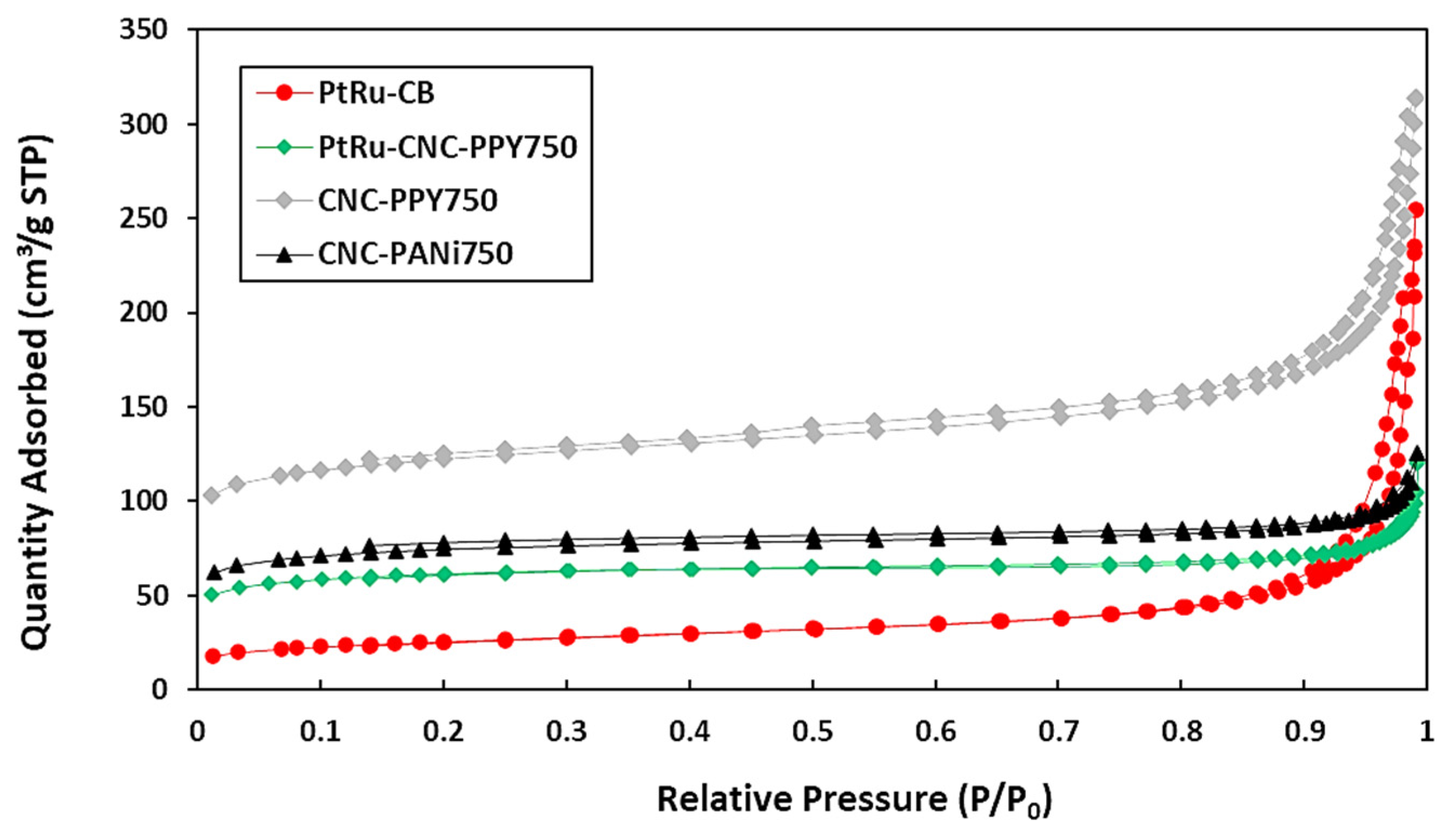
| Samples | CNC-PANI750 | CNC-PPy750 | PtRu/CNC-Ppy750 | PtRu/CB |
|---|---|---|---|---|
| SBET (m2g−1) | 253.86 | 416.10 | 210.15 | 89.62 |
| VTotal (cm3g−1) | 0.16 | 0.41 | 0.06 | 0.12 |
| Smesopore (m2g−1) | 74.02 | 131.10 | 65.39 | 61.02 |
| SMicropore (m2g−1) | 179.84 | 285.00 | 144.76 | 28.60 |
| Dpore (nm) | 25.9 | 39.2 | 2.8 | 3.1 |
| Sample | Onset Potential (V vs. Ag/AgCl) | Peak Potential (V vs. Ag/AgCl) | ECSA (m2g−1) | Current Density (mA mg−1) | CO Tolerance (If/Ib) |
|---|---|---|---|---|---|
| PtRu/CNC-PPy750 | 0.325 | 0.71 | 16.23 | 427 | 2.34 |
| PtRu/CB | 0.391 | 0.68 | 14.06 | 248 | 1.25 |
| Catalysts | Catalyst Loading (wt. %) | Scan Rate (mVs−1) | Current Density (mAmg−1) | Reference |
|---|---|---|---|---|
| PtRu/CNC-PPy750 | 20 | 25 | 427 | this research |
| PtRu/CB | 20 | 25 | 248 | this research |
| PtRu/CNF | 20 | 20 | 186.29 | Abdullah et al., 2018 [58] |
| PtRuFeNi/MWCNT | 20 | 50 | 31 | Basri et al., 2014 [59] |
| PtRu-TNT | 10 | 50 | 3.3 mA/cm2 | Abdullah et al., 2016 [46] |
| PtRu/HollowCarbon Sphere | - | 50 | 323.6 | Liu et al., 2013 [56] |
| PtRu/CeCNF | 15 | 20 | 290 | Kunitomo et al., 2016 [60] |
| PtRu/CNT | 40 | 50 | 335 | Cheng et al., 2014 [61] |
| Pt/Graphene sheet | - | 20 | 202.2 | Zhao et al., 2014 [62] |
| PtRu/Graphene | 40 | 50 | 200 | Woo et al., 2013 [63] |
| PtRu/MWCNT | - | 50 | ~24 | Chen et al., 2017 [64] |
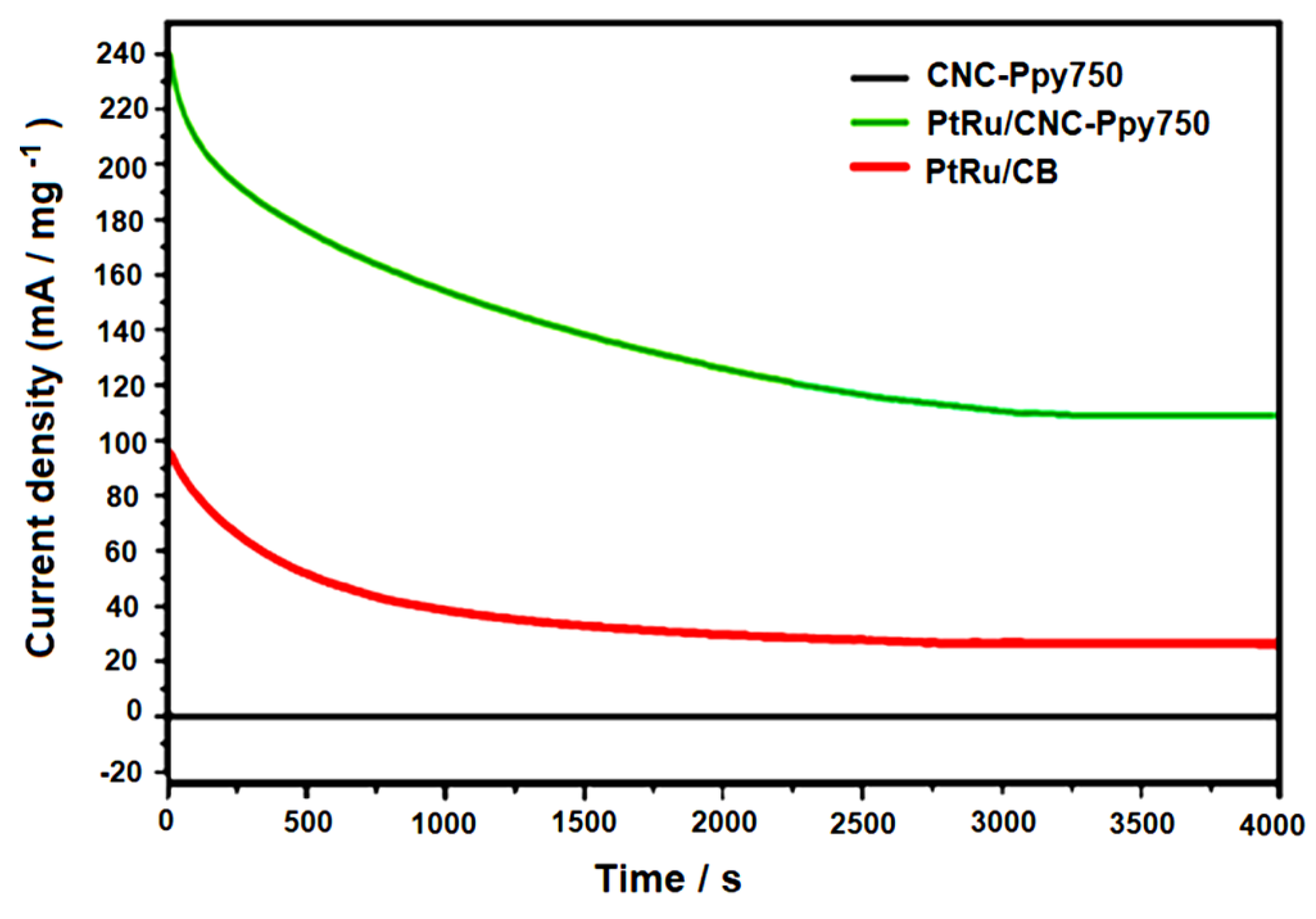
| Electrocatalysts | ji (mA/mg) | jf (mA/mg) | Retention Value (%) |
|---|---|---|---|
| PtRu/CNC-PPy750 | 241.5 | 113.8 | 47.12 |
| PtRu/CB | 98.0 | 30.5 | 31.12 |
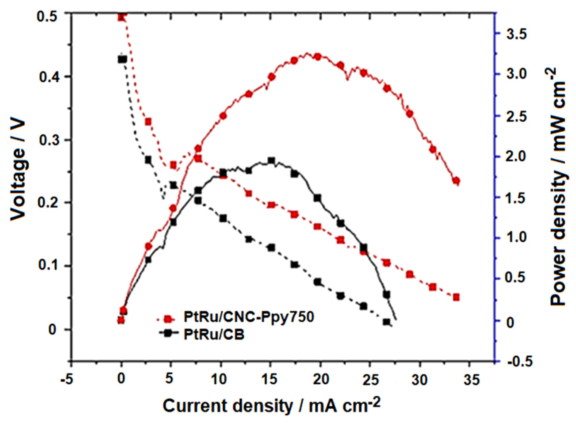
| Electrocatalysts | Electrocatalyst Loading (mg/cm2) | Power Density (mW/cm2) | Reference |
|---|---|---|---|
| PtRu/CNC-Ppy750 | 2 | 3.35 | This study |
| PtRu/CB | 2 | 1.95 | This study |
| PtRu/C | 2 | 2.20 | Abdullah et al., 2018 [58] |
| PtRu/C | 2 | 1.7 | Hashim et al., 2009 [69] |
| PtRu/C | 2 | 3.0 | Shimizu et al., 2004 [70] |
Disclaimer/Publisher’s Note: The statements, opinions and data contained in all publications are solely those of the individual author(s) and contributor(s) and not of MDPI and/or the editor(s). MDPI and/or the editor(s) disclaim responsibility for any injury to people or property resulting from any ideas, methods, instructions or products referred to in the content. |
© 2024 by the authors. Licensee MDPI, Basel, Switzerland. This article is an open access article distributed under the terms and conditions of the Creative Commons Attribution (CC BY) license (https://creativecommons.org/licenses/by/4.0/).
Share and Cite
Ramli, Z.A.C.; Pasupuleti, J.; Kamarudin, S.K.; Zainoodin, A.M.; Isahak, W.N.R.W.; Koh, S.P.; Kiong, S.T. Harnessing the Potential of Hollow Graphitic Carbon Nanocages for Enhanced Methanol Oxidation Using PtRu Nanoparticles. Polymers 2024, 16, 2684. https://doi.org/10.3390/polym16192684
Ramli ZAC, Pasupuleti J, Kamarudin SK, Zainoodin AM, Isahak WNRW, Koh SP, Kiong ST. Harnessing the Potential of Hollow Graphitic Carbon Nanocages for Enhanced Methanol Oxidation Using PtRu Nanoparticles. Polymers. 2024; 16(19):2684. https://doi.org/10.3390/polym16192684
Chicago/Turabian StyleRamli, Zatil Amali Che, Jagadeesh Pasupuleti, Siti Kartom Kamarudin, Azran Mohd Zainoodin, Wan Nor Roslam Wan Isahak, S. P. Koh, and Sieh Tiong Kiong. 2024. "Harnessing the Potential of Hollow Graphitic Carbon Nanocages for Enhanced Methanol Oxidation Using PtRu Nanoparticles" Polymers 16, no. 19: 2684. https://doi.org/10.3390/polym16192684
APA StyleRamli, Z. A. C., Pasupuleti, J., Kamarudin, S. K., Zainoodin, A. M., Isahak, W. N. R. W., Koh, S. P., & Kiong, S. T. (2024). Harnessing the Potential of Hollow Graphitic Carbon Nanocages for Enhanced Methanol Oxidation Using PtRu Nanoparticles. Polymers, 16(19), 2684. https://doi.org/10.3390/polym16192684