

Composite Fiber Wrapping Techniques for Enhanced Concrete Mechanics

 and
and
Abstract
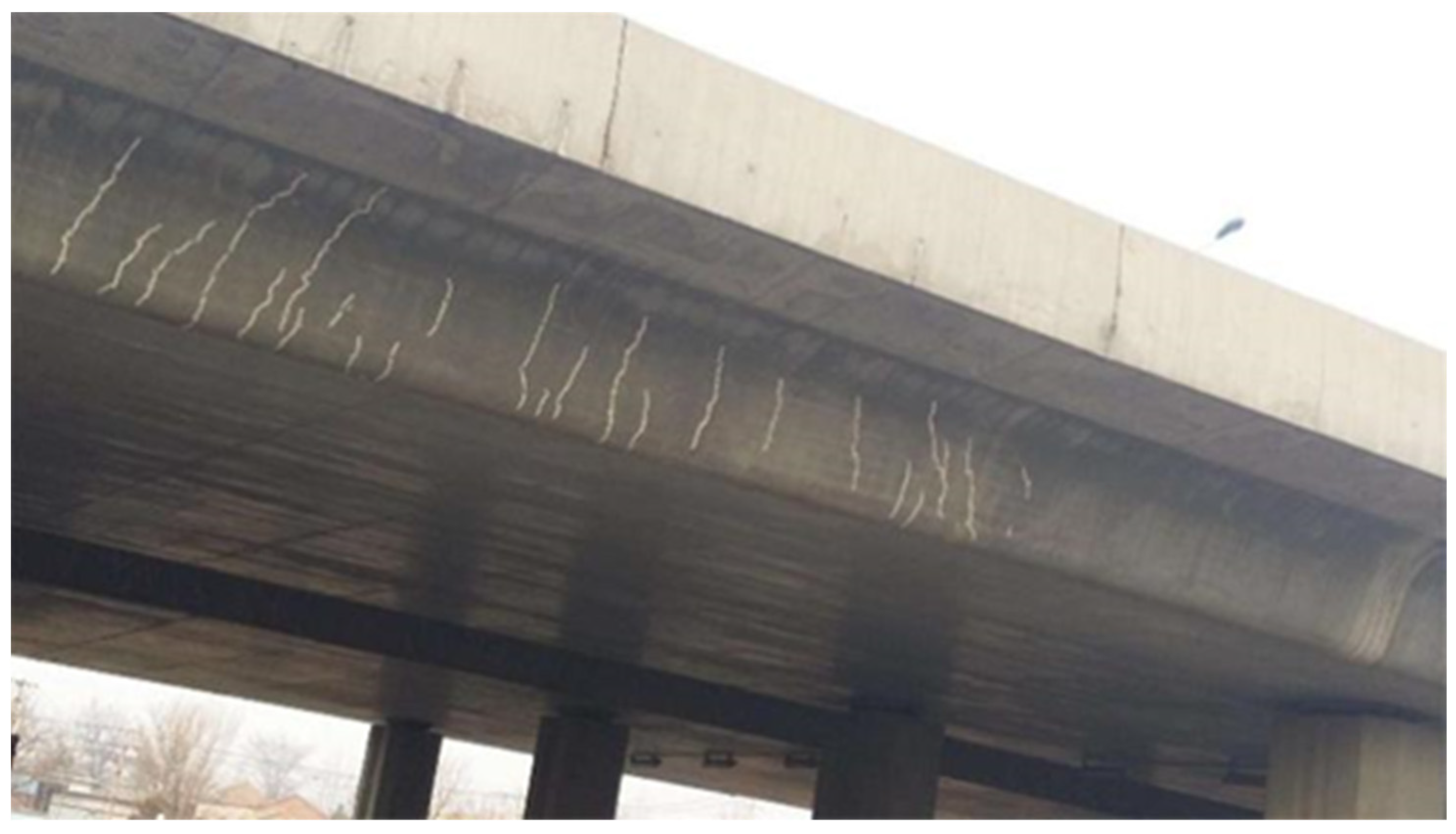
1. Introduction
2. Material and Method
2.1. Materials
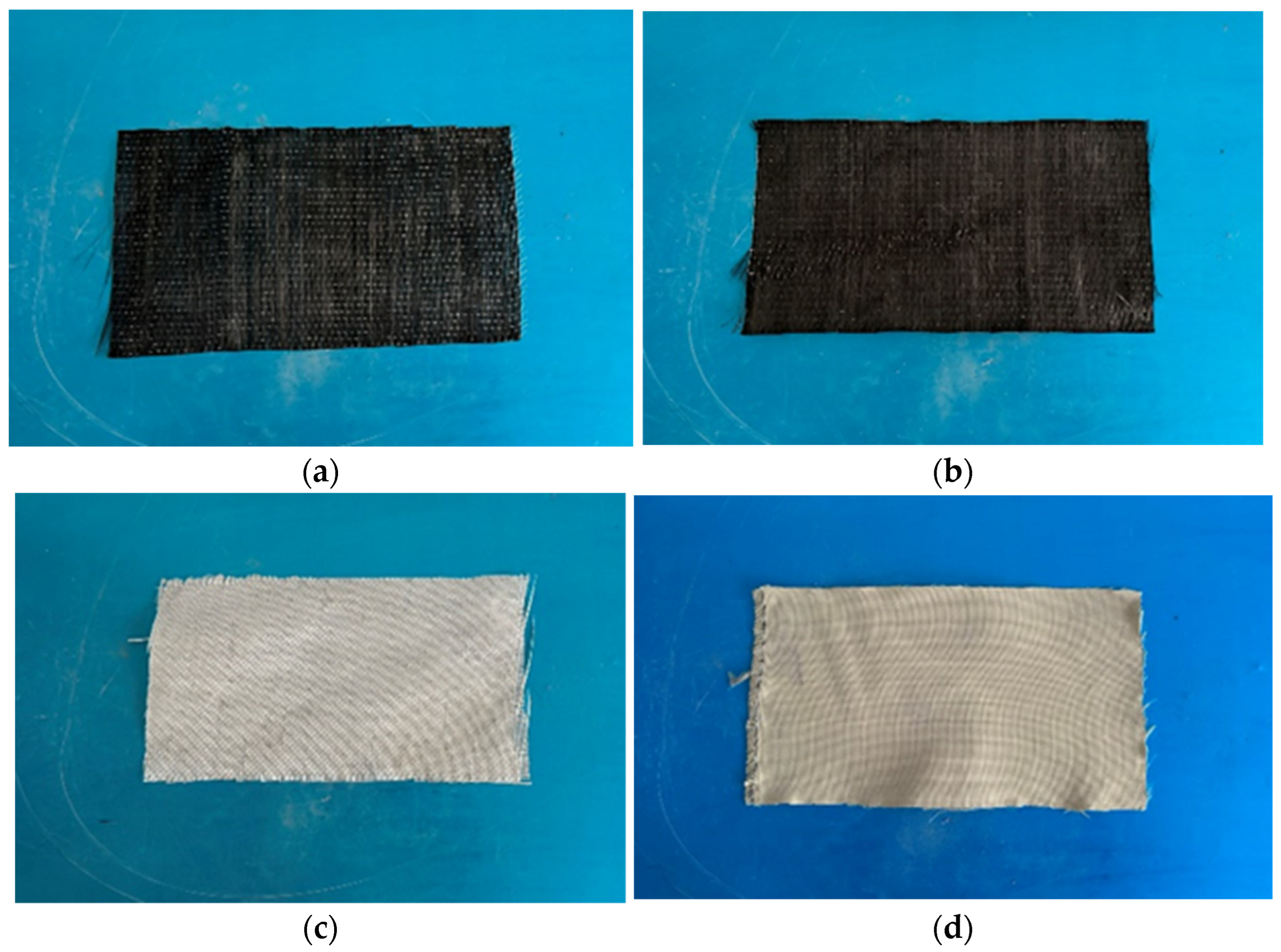
2.1.1. Fiber-Reinforced Polymer (FRP)
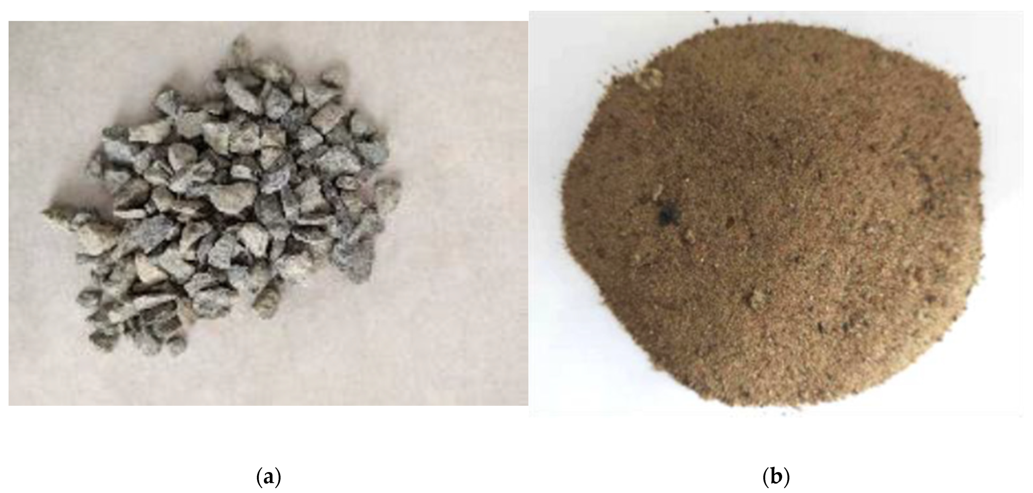
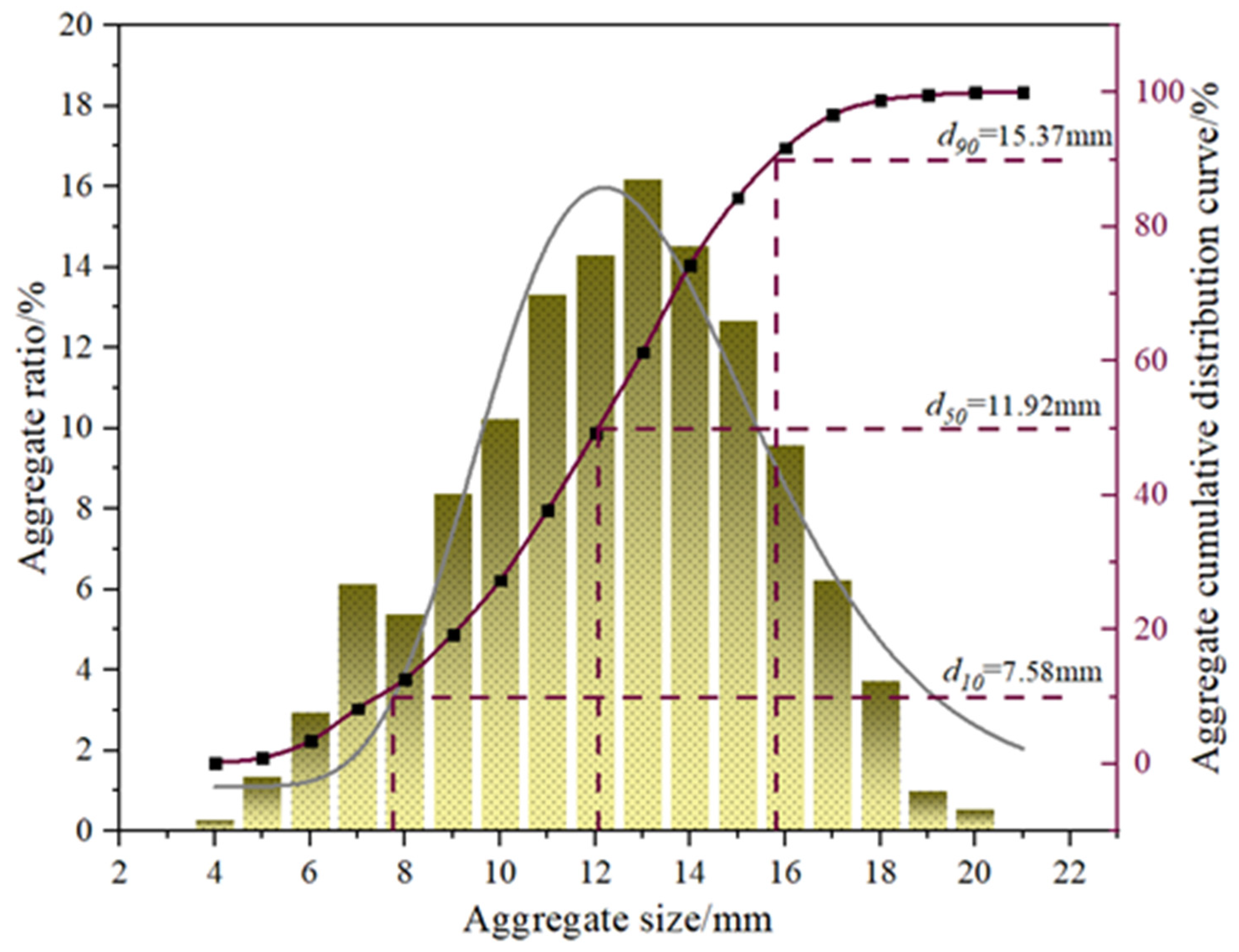
2.1.2. Aggregate
2.1.3. Cement
2.1.4. Water
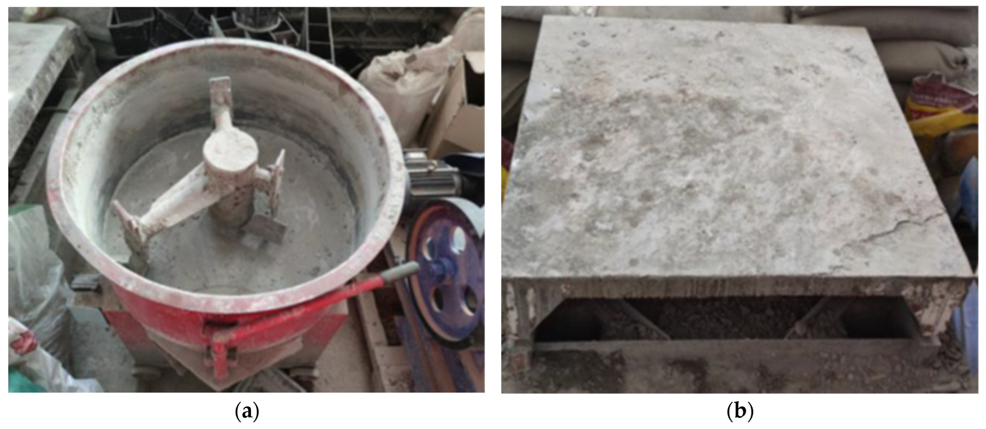
2.2. Specimen Preparation and Test Methods
2.2.1. Specimen Mix Proportion
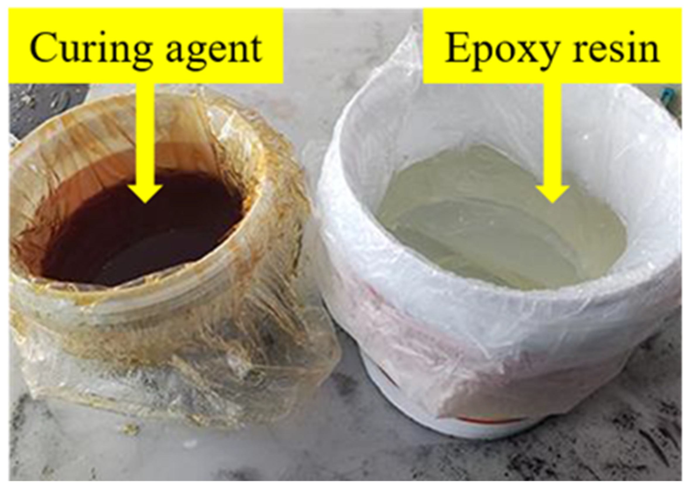
2.2.2. FRP Bonding
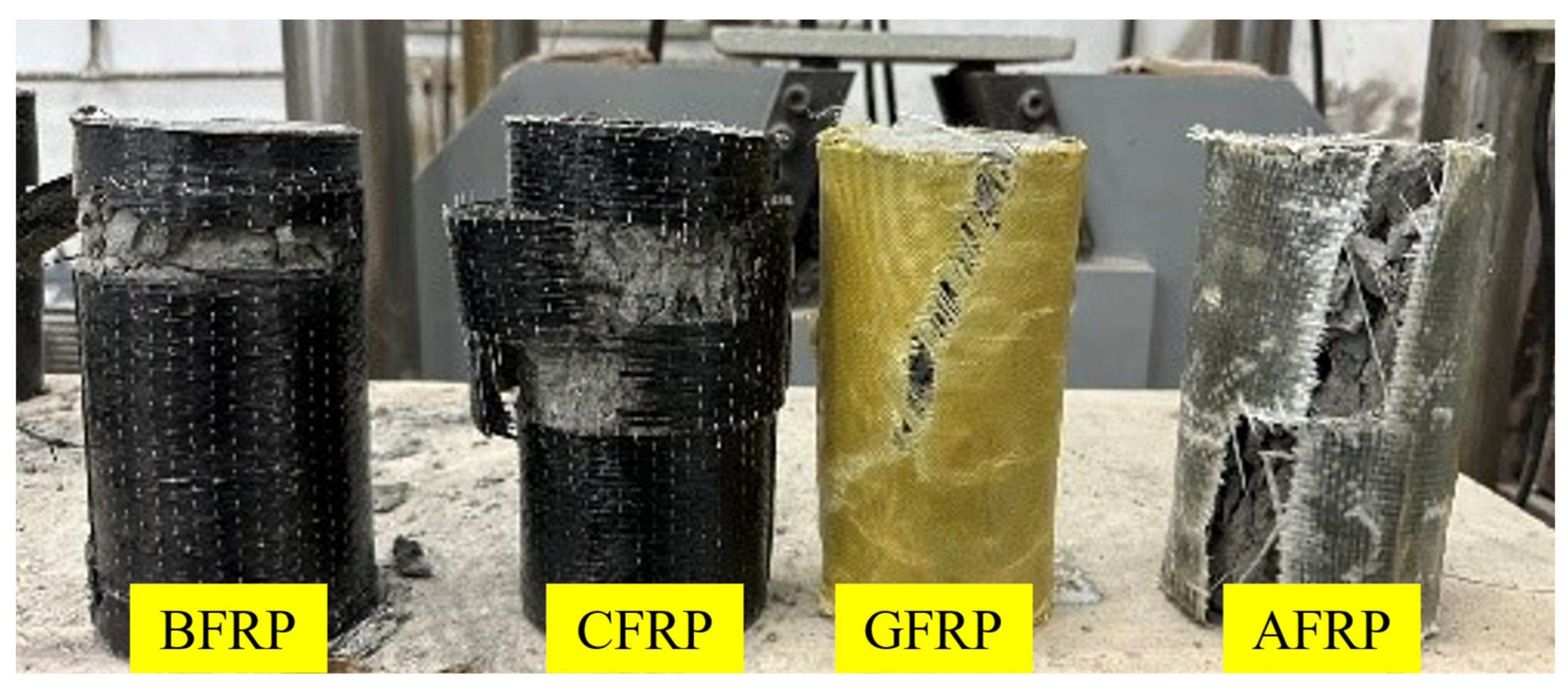
2.3. Axial Compression Test
3. Results and Discussion
3.1. Single-Layer FRP Reinforcement
3.1.1. Axial Compressive Strength
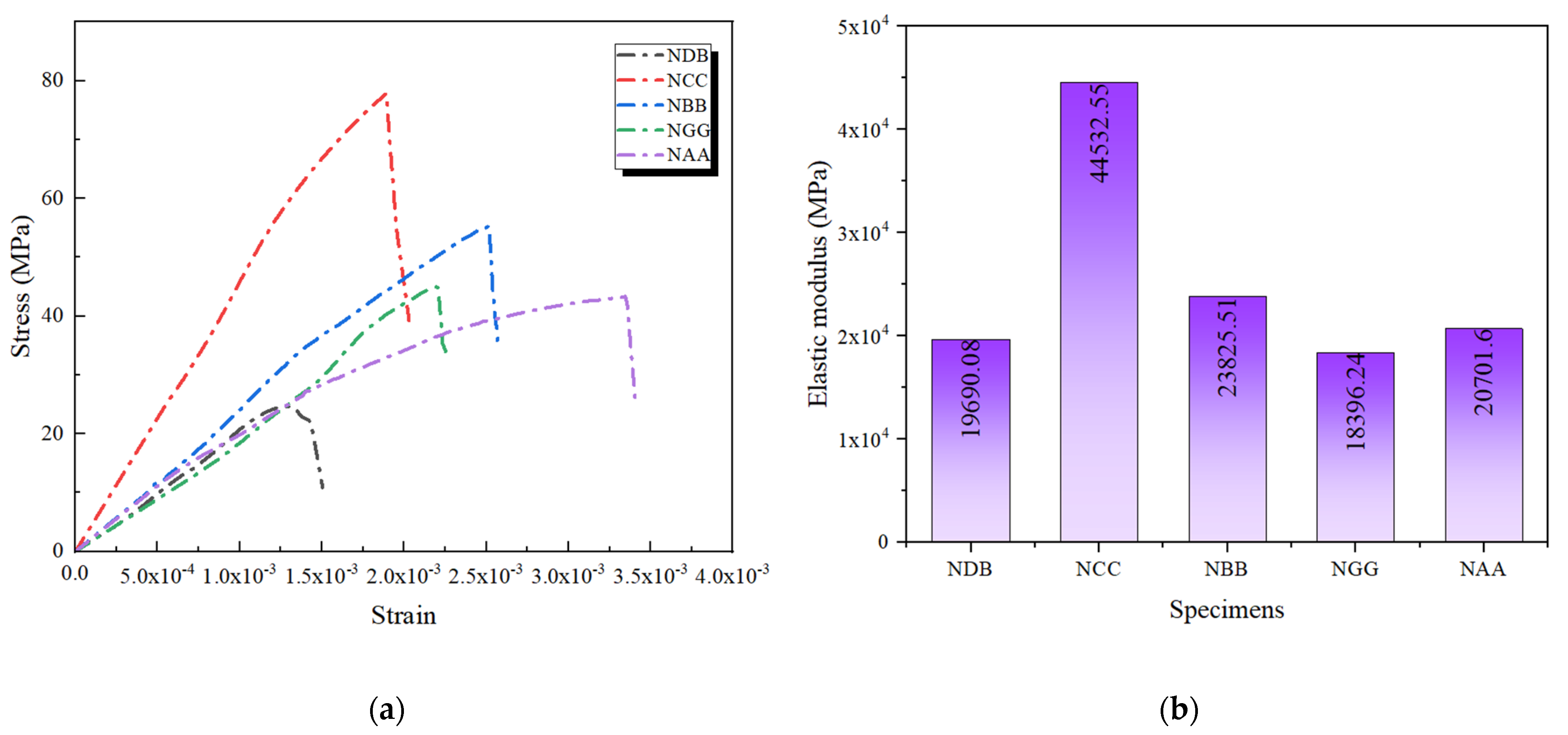
3.1.2. Stress–Strain Curves
3.1.3. Elastic Modulus
3.2. Double-Layer FRP Reinforcement
3.2.1. Compressive Strength
3.2.2. Stress–Strain Curves
3.2.3. Elastic Modulus
- In double-layer GFRP reinforcement, an additional interface between the FRP layers and the concrete introduces a new contact surface. If the epoxy resin adhesive is not applied uniformly, it may increase porosity at the interface, thereby reducing overall stiffness.
- Interlayer slippage can occur in double-layer GFRP reinforcement, weakening stress transfer efficiency, particularly pronounced in materials like GFRP with a lower elastic modulus.
- The uneven stress distribution is a crucial factor.
3.3. Composite FRP Reinforcement
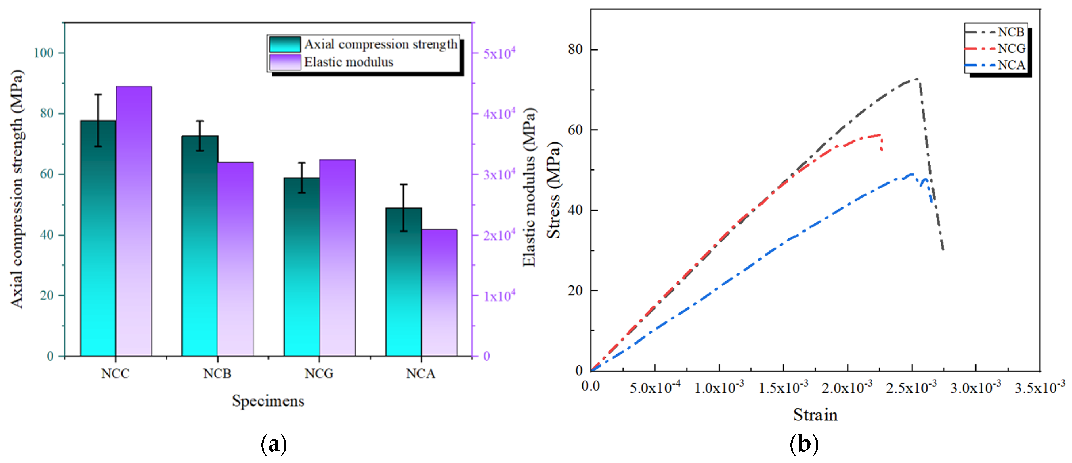
3.3.1. CFRP as the Outer Layer
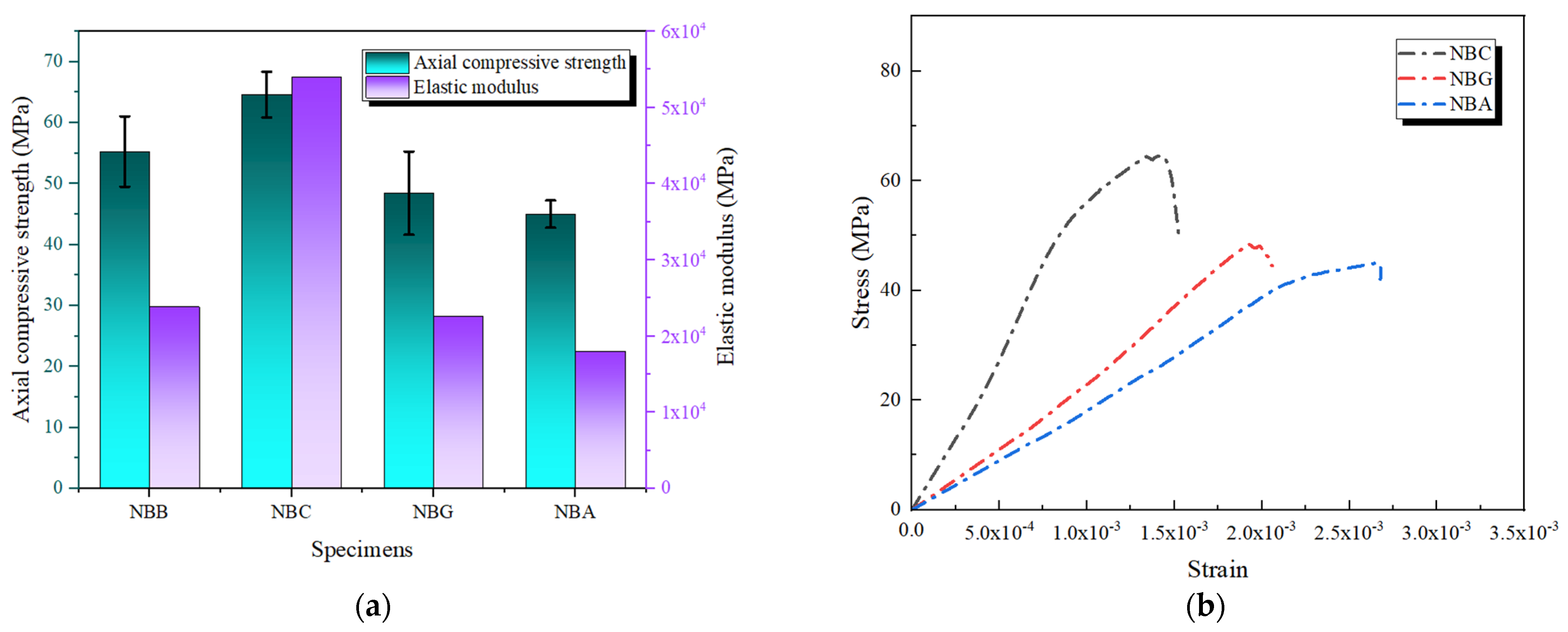
3.3.2. BFRP as the Outer Layer
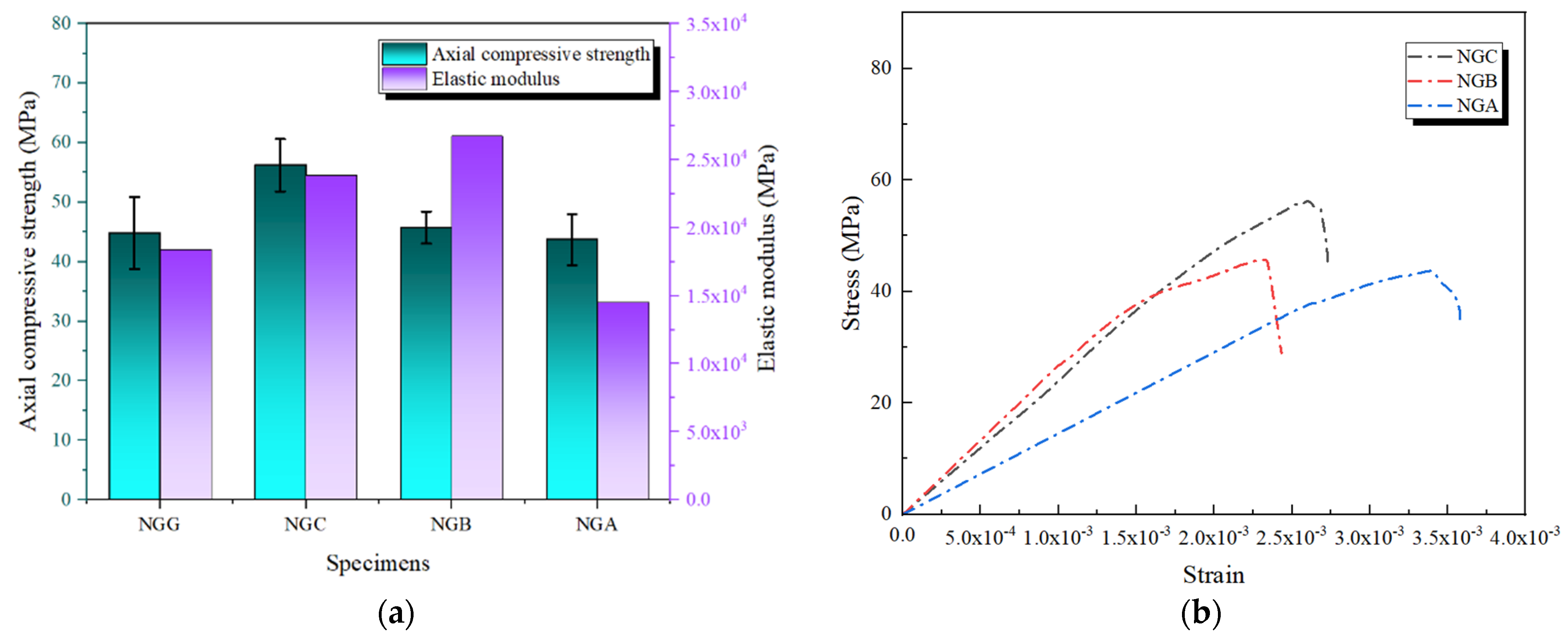
3.3.3. GFRP as the Outer Layer
3.3.4. AFRP as the Outer Layer
4. Finite Element Numerical Simulation
4.1. Constitutive Relationships
4.1.1. Constitutive Relationship of Concrete
4.1.2. Constitutive Relationship of FRP
4.2. Parameter Settings
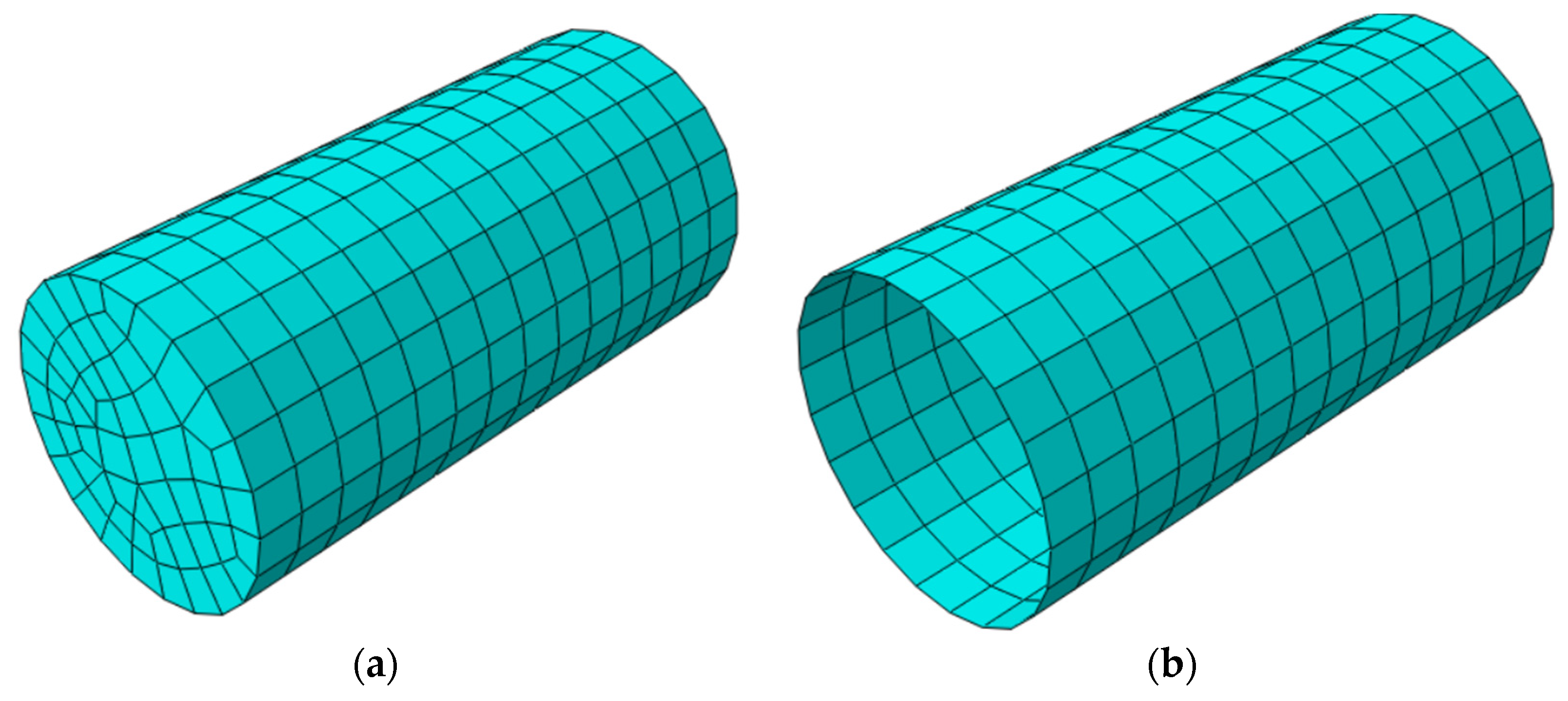
4.2.1. Element Selection and Mesh Generation
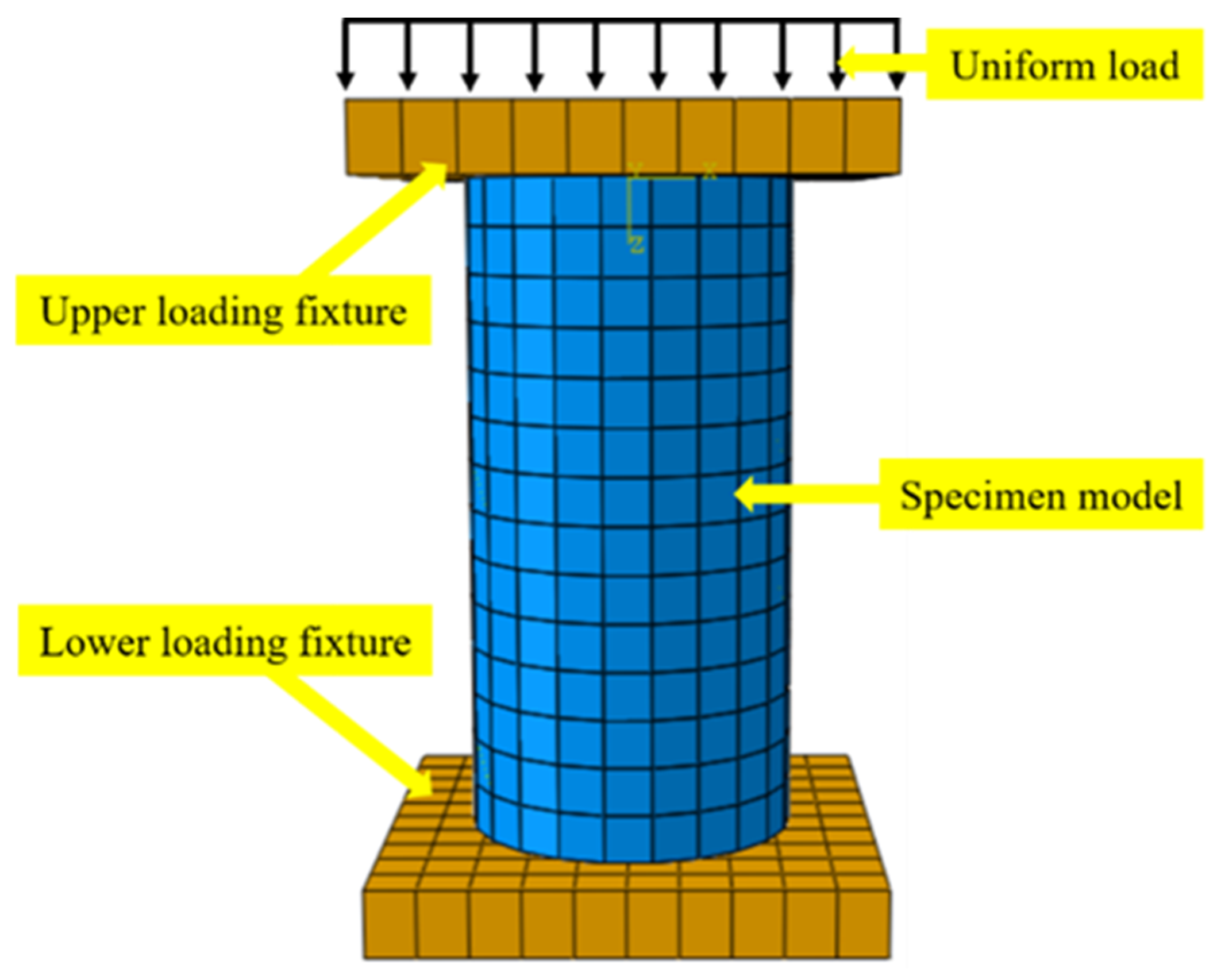
4.2.2. Boundary Conditions and Loading
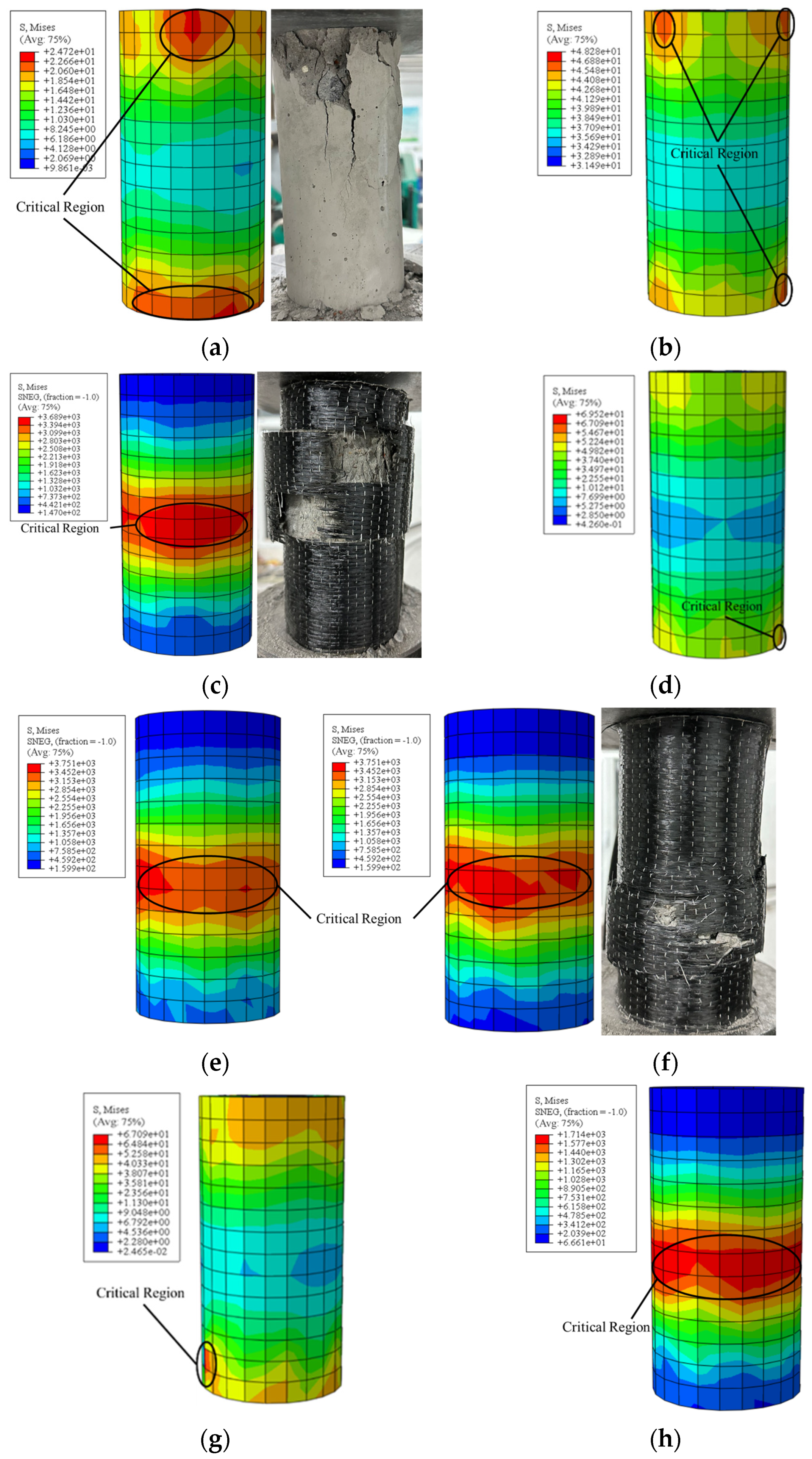
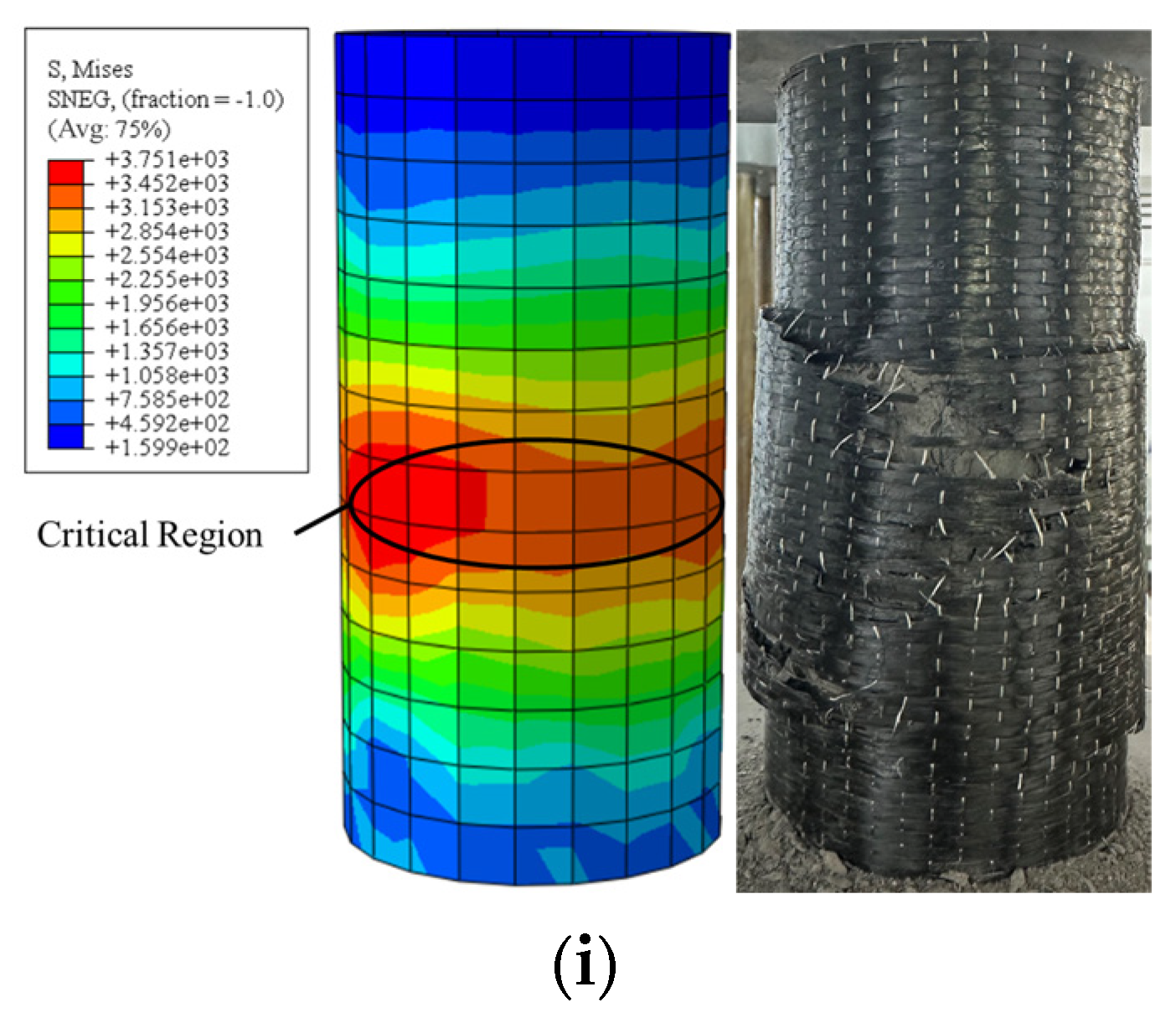
4.3. Finite Element Results Analysis
5. Conclusions
- (1)
- Among the single-layer reinforcements, CFRP exhibited the best performance. This is attributed to its high tensile strength and elastic modulus, which effectively constrained concrete deformation, thereby enhancing the load-bearing capacity of the specimens. BFRP, GFRP, and AFRP demonstrated better ductility and energy absorption, but their reinforcement effects under high-stress conditions were relatively limited.
- (2)
- Double-layer CFRP reinforcement showed the most optimal overall performance, significantly improving the compressive strength and stiffness of the specimens. In the ABAQUS simulations, the NCC specimens exhibited more uniform stress distribution with fewer instances of localized stress concentration. While other double-layer combinations, such as those involving BFRP and GFRP, also showed some reinforcement effects, their contributions to overall structural stiffness were limited due to their lower elastic modulus.
- (3)
- In composite reinforcement when CFRP was used as the outer layer, it formed a solid synergistic effect with the inner FRP. This was particularly evident when combined with BFRP or GFRP, resulting in high axial compressive strength and stiffness. However, when BFRP and GFRP were used as the outer layers, although there was an improvement in ductility, the enhancement in axial compressive performance and stiffness was not as pronounced as with CFRP. When AFRP was used as the outer reinforcement material, its high toughness somewhat enhanced the structure’s ductility. However, its overall reinforcement effectiveness was mainly dependent on the performance of the inner FRP, resulting in a relatively weaker performance overall.
Author Contributions
Funding
Institutional Review Board Statement
Data Availability Statement
Conflicts of Interest
References
- Cao, X.-Y.; Shen, D.; Feng, D.-C.; Wang, C.-L.; Qu, Z.; Wu, G. Seismic retrofitting of existing frame buildings through externally attached sub-structures: State of the art review and future perspectives. J. Build. Eng. 2022, 57, 104904. [Google Scholar] [CrossRef]
- Hu, J.; Hu, J.; Zhang, S.; Zhang, S.; Chen, E.; Chen, E.; Li, W.; Li, W. A review on corrosion detection and protection of existing reinforced concrete (RC) structures. Constr. Build. Mater. 2022, 325, 126718. [Google Scholar] [CrossRef]
- Mo, J.; Uy, B.; Li, D.; Thai, H.-T.; Tran, H. A review of the behaviour and design of steel–concrete composite shear walls. In Structures; Elsevier: Amsterdam, The Netherlands, 2021; Volume 31, pp. 1230–1253. [Google Scholar]
- Niu, J.; Xu, W.; Li, J.; Liang, J. Influence of Cross-Sectional Shape on the Mechanical Properties of Concrete Canvas and CFRP-Reinforced Columns. Adv. Mater. Sci. Eng. 2021, 2021, 5541587. [Google Scholar] [CrossRef]
- Dai, J.; Bai, Y.; Teng, G.J. Behavior and Modeling of Concrete Confined with FRP Composites of Large Deformability. J. Compos. Constr. 2011, 15, 963–973. [Google Scholar] [CrossRef]
- Liu, X.; Wu, T.; Chen, H.; Liu, Y. Compressive stress-strain behavior of CFRP-confined lightweight aggregate concrete reinforced with hybrid fibers. Compos. Struct. 2020, 244, 112288. [Google Scholar] [CrossRef]
- Hemida OA, R.; Abdalla, H.A.; Fouad HE, E. Flexural behaviour of recycled reinforced concrete beams strengthened/repaired with CFRP laminates. J. Eng. Appl. Sci. 2023, 70, 64. [Google Scholar] [CrossRef]
- Ouyang, L.J.; Gao, W.Y.; Zhen, B.; Lu, Z.D. Seismic retrofit of square reinforced concrete columns using basalt and carbon fiber-reinforced polymer sheets: A comparative study. Compos. Struct. 2017, 162, 294–307. [Google Scholar] [CrossRef]
- Khalifa, A.; Nanni, A. Improving shear capacity of existing RC T-section beams using CFRP composites. Cem. Concr. Compos. 2000, 27, 165–174. [Google Scholar] [CrossRef]
- Raza, A.; Ali, B.; Nawaz, M.A.; Ahmed, I. Structural performance of FRP-RC compression members wrapped with FRP composites. In Structures; Elsevier: Amsterdam, The Netherlands, 2020; Volume 27, pp. 1693–1709. [Google Scholar]
- GB 50728-2011; Technical Code for Safety Appraisal of Engineering Structural Strengthening Materials. Architecture Publishing & Media Co., Ltd.: Beijing, China, 2012.
- Mazzuca, P.; Pisani, B.; Firmo, J.P.; Ombres, L. Tensile and bond properties at elevated temperatures of a PBO-FRCM composite system for strengthening concrete elements: Experimental and analytical investigations. Constr. Build. Mater. 2024, 432, 136519. [Google Scholar] [CrossRef]
- GB/T 14685-2011; Pebbie and Crushed Stone for Building. Architecture Publishing & Media Co., Ltd.: Beijing, China, 2011.
- JGJ 52-2006; Standard for Technical Requirements and Test Method of Sand and Crushed Stone (or Gravel) for Ordinary Concrete. Architecture Publishing & Media Co., Ltd.: Beijing, China, 2006.
- GB 175-2007; Common Portland Cement. Architecture Publishing & Media Co., Ltd.: Beijing, China, 2007.
- JGJ 63-2006; Standard if Water Fir Cibcreke. Architecture Publishing & Media Co., Ltd.: Beijing, China, 2006.
- GB/T 50080-2002; Standard for Test Method of Performance on Ordinary Fresh Concrete. Architecture Publishing & Media Co., Ltd.: Beijing, China, 2002.
- GB/T 50081-2019; Standard for Test Methods of Concrete Physical and Mechanical Properties. Architecture Publishing & Media Co., Ltd.: Beijing, China, 2019.
- Raza, A.; Khan, Q.Z.; Ahmad, A. Prediction of axial compressive strength for FRP-confined concrete compression members. KSCE J. Civ. Eng. 2020, 24, 2099–2109. [Google Scholar] [CrossRef]
- Ahmet Yaşar, B.; Kose, M.M.; Avğın, S.; Temiz, H. Determination of elasticity modulus for low strength concrete. El-Cezeri 2020, 7, 1384–1397. [Google Scholar]
- Benmokrane, B.; Zhang, B.; Chennouf, A. Tensile properties and pullout behaviour of AFRP and CFRP rods for grouted anchor applications. Constr. Build. Mater. 2000, 14, 157–170. [Google Scholar] [CrossRef]
- Ou, Y.; Zhu, D.; Zhang, H.; Huang, L.; Yao, Y.; Li, G.; Mobasher, B. Mechanical characterization of the tensile properties of glass fiber and its reinforced polymer (GFRP) composite under varying strain rates and temperatures. Polymers 2016, 8, 196. [Google Scholar] [CrossRef] [PubMed]
- Qaidi, S.; Al-Kamaki, Y.S.S.; Al-Mahaidi, R.; Mohammed, A.S.; Ahmed, H.U.; Zaid, O.; Althoey, F.; Ahmad, J.; Isleem, H.F.; Bennetts, I. Investigation of the effectiveness of CFRP strengthening of concrete made with recycled waste PET fine plastic aggregate. PLoS ONE 2022, 17, e0269664. [Google Scholar] [CrossRef]
- Tu, J.; Xie, H.; Gao, K.; Li, Z.; Zhang, J. Durability prediction of GFRP rebar based on elastic modulus degradation. Front. Mater. 2019, 6, 258. [Google Scholar] [CrossRef]
- Li, Y.; Wang, Y.; Ou, J. Mechanical behavior of BFRP-steel composite plate under axial tension. Polymers 2014, 6, 1862–1876. [Google Scholar] [CrossRef]
- Kim, Y.J. Flexural response of concrete beams prestressed with AFRP tendons: Numerical investigation. J. Compos. Constr. 2010, 14, 647–658. [Google Scholar] [CrossRef]
- Yu, Q.-Q.; Zhao, Y.-Z.; Wu, H.; Wang, Z.; Zhu, Z.-Y. Experimental study on AFRP-to-concrete bond behavior subjected to underground water. Compos. Struct. 2023, 306, 116565. [Google Scholar] [CrossRef]
- Anas, S.M.; Shariq, M.; Alam, M. Performance of axially loaded square RC columns with single/double confinement layer (s) and strengthened with C-FRP wrapping under close-in blast. Mater. Today Proc. 2022, 58, 1128–1141. [Google Scholar] [CrossRef]
- Yuan, C.; Chen, W.; Pham, T.M.; Hao, H.; Chen, L.; Zhang, M. New epoxy anchor for better bonding between FRP sheets and concrete. Constr. Build. Mater. 2020, 248, 118628. [Google Scholar] [CrossRef]
- Durgadevi, S.; Karthikeyan, S.; Lavanya, N.; Kavitha, C. A review on retrofitting of reinforced concrete elements using FRP. Mater. Today Proc. 2021, 45, 1050–1054. [Google Scholar] [CrossRef]
- Ma, G.; Chen, X.; Yan, L.; Hwang, H.-J. Effect of pre-damage on compressive properties of circular RC columns repaired with BFRP composites: Testing and modeling. Compos. Struct. 2020, 247, 112483. [Google Scholar] [CrossRef]
- Ranolia, K.V.; Thakkar, B.K.; Rathod, J.D. Effect of different patterns and cracking in FRP wrapping on compressive strength of confined concrete. Procedia Eng. 2013, 51, 169–175. [Google Scholar] [CrossRef]
- Jiang, F.; Han, X.; Wang, Y.; Wang, P.; Zhao, T.; Zhang, K. Effect of freeze-thaw cycles on tensile properties of CFRP, bond behavior of CFRP-concrete, and flexural performance of CFRP-strengthened concrete beams. Cold Reg. Sci. Technol. 2022, 194, 103461. [Google Scholar] [CrossRef]
- Tang, Y.; Sun, Z.; Wei, Y.; Zou, X. Compressive behavior and design method of BFRP bars constrained with a BFRP spiral with different spacings in concrete members. Eng. Struct. 2022, 268, 114757. [Google Scholar] [CrossRef]
- Li, P.-D.; Zhao, Y.; Wu, Y.-F.; Lin, J.-P. Effect of defects in adhesive layer on the interfacial bond behaviors of externally bonded CFRP-to-concrete joints. Eng. Struct. 2023, 278, 115495. [Google Scholar] [CrossRef]
- Liu, Y.; Zhang, H.-T.; Tafsirojjaman, T.; Dogar, A.U.R.; AlAjarmeh, O.; Yue, Q.-R.; Manalo, A. A novel technique to improve the compressive strength and ductility of glass fiber reinforced polymer (GFRP) composite bars. Constr. Build. Mater. 2022, 326, 126782. [Google Scholar] [CrossRef]
- Yang, S.; Liu, C.; Sun, Z.; Xu, M.; Feng, Y. Effects of resin pre-coating treatment and fibre reinforcement on adhesive bonding between CFRP sheet and concrete. Compos. Struct. 2022, 292, 115610. [Google Scholar] [CrossRef]
- Hardan, S.A.; Aules, W.A. Analysis of CFRP confined concrete cylinders by using ABAQUS software. Tikrit J. Eng. Sci. 2022, 29, 28–40. [Google Scholar] [CrossRef]
- Le Thanh, C.; Minh, H.L.; Sang-To, T. A nonlinear concrete damaged plasticity model for simulation reinforced concrete structures using ABAQUS. Frat. Ed Integrità Strutt. 2022, 16, 232–242. [Google Scholar] [CrossRef]
- Naser, M.Z.; Hawileh, R.A.; Abdalla, J. Modeling strategies of finite element simulation of reinforced concrete beams strengthened with FRP: A review. J. Compos. Sci. 2021, 5, 19. [Google Scholar] [CrossRef]
- Zheng, Z.; Du, Y.; Chen, Z.; Li, S.; Niu, J. Experimental and theoretical studies of FRP-Steel composite plate under static tensile loading. Constr. Build. Mater. 2021, 271, 121501. [Google Scholar] [CrossRef]
- Lam, L.; Teng, J.G. Design-oriented stress–strain model for FRP-confined concrete. Constr. Build. Mater. 2003, 17, 471–489. [Google Scholar] [CrossRef]
- Kwan, A.K.H.; Dong, C.X.; Ho, J.C.M. Axial and lateral stress–strain model for FRP confined concrete. Eng. Struct. 2015, 99, 285–295. [Google Scholar] [CrossRef]
- Kudela, J.; Matousek, R. Recent advances and applications of surrogate models for finite element method computations: A review. Soft Comput. 2022, 26, 13709–13733. [Google Scholar] [CrossRef]
- Ji, Y.; Liu, W.; Jia, Y.; Li, W. Durability investigation of carbon fiber reinforced concrete under salt-freeze coupling effect. Materials 2021, 14, 6856. [Google Scholar] [CrossRef]
- Ji, Y.; Li, Z.; Xu, W.; Li, W. Mechanical damage mechanism investigation on CFRP strengthened recycled red brick concrete. Rev. Adv. Mater. Sci. 2024, 63, 20230178. [Google Scholar] [CrossRef]
- Raza, A.; Shah, S.A.R.; Khan, A.R.; Aslam, M.A.; Khan, T.A.; Arshad, K.; Hussan, S.; Sultan, A.; Shahzadi, G.; Waseem, M. Sustainable FRP-confined symmetric concrete structures: An application experimental and numerical validation process for reference data. Appl. Sci. 2020, 10, 333. [Google Scholar] [CrossRef]
- Ji, Y.; Pei, Z.; Xu, W.; Li, Z.; Li, Y.; Jia, Y. Deterioration performance analysis of recycled brick concrete subjected to freezing and thawing effect. Case Stud. Constr. Mater. 2024, 20, e02722. [Google Scholar] [CrossRef]
- Ji, Y.; Wang, D. Durability of recycled aggregate concrete in cold regions. Case Stud. Constr. Mater. 2022, 17, e01475. [Google Scholar] [CrossRef]
- Raza, A.; Rafique, U.; Masood, B.; Ali, B.; Haq, F.U.; Nawaz, M.A. Performance evaluation of hybrid fiber reinforced low strength concrete cylinders confined with CFRP wraps. In Structures; Elsevier: Amsterdam, The Netherlands, 2021; Volume 31, pp. 182–189. [Google Scholar]
- Wang, H.C.; Zhao, J.; Li, J.; Liu, K.; Braithwaite, C.H.; Zhang, Q.B. Dynamic mechanical properties and fracturing behaviour of concrete under biaxial compression. Constr. Build. Mater. 2021, 301, 124085. [Google Scholar] [CrossRef]


| FRP Type | Thickness (mm) | Tensile Strength (MPa) | Tensile Elastic Modulus (MPa) | Elongation (%) |
|---|---|---|---|---|
| CFRP | 0.167 | 3520 | 267 | 1.78 |
| BFRP | 0.190 | 3000 | 120 | 1.60 |
| GFRP | 0.200 | 2500 | 80 | 2.30 |
| AFRP | 0.155 | 2106 | 117.8 | 1.75 |
| Test Items | Fineness/% | Setting Time/(min) | Compressive Strength | Flexural Strength | |||
|---|---|---|---|---|---|---|---|
| Initial Setting Time | Final Setting Time | 3 d | 28 d | 3 d | 28 d | ||
| Standard value | ≤10.0 | ≥45 | ≤600 | ≥17 | ≥42.5 | ≥3.5 | ≥6.5 |
| Detection value | 3.7 | 148 | 374 | 25.7 | 48.2 | 4.7 | 7.5 |
| Materials | Cement | Coarse Aggregate | Fine Aggregate | Water |
|---|---|---|---|---|
| Content (kg/m3) | 213 | 387 | 635 | 1169 |
| Specimen | Number of FRP Layers | Outer FRP Type | Inner FRP Type |
|---|---|---|---|
| BDB | 0 | — | — |
| NC | 1 | CFRP | — |
| NB | 1 | BFRP | — |
| NG | 1 | GFRP | — |
| NA | 1 | AFRP | — |
| NCC | 2 | CFRP | CFRP |
| NBB | 2 | BFRP | BFRP |
| NGG | 2 | GFRP | GFRP |
| NAA | 2 | AFRP | AFRP |
| NCB | 2 | CFRP | BFRP |
| NCG | 2 | CFRP | GFRP |
| NCA | 2 | CFRP | AFRP |
| NBC | 2 | BFRP | CFRP |
| NBG | 2 | BFRP | GFRP |
| NBA | 2 | BFRP | AFRP |
| NGC | 2 | GFRP | CFRP |
| NGB | 2 | GFRP | BFRP |
| NGA | 2 | GFRP | AFRP |
| NAC | 2 | AFRP | CFRP |
| NAB | 2 | AFRP | BFRP |
| NAG | 2 | AFRP | GFRP |
| Specimen | Axial Compressive Strength (MPa) | Strength Improvement Over Non-FRP Group (%) | Ultimate Load (MPa) | Ultimate Compressive Strain (×10−3) | Elastic Modulus (×104 MPa) |
|---|---|---|---|---|---|
| NDB | 24.66 | 0.00 | 28.52 | 1.29 | 1.969 |
| NC | 45.07 | 82.77 | 46.59 | 1.56 | 3.275 |
| NB | 39.64 | 60.75 | 42.14 | 1.97 | 2.063 |
| NG | 36.01 | 46.03 | 42.53 | 1.72 | 2.015 |
| NA | 34.07 | 38.16 | 37.49 | 2.19 | 1.712 |
| NCC | 77.81 | 215.53 | 78.03 | 1.89 | 4.453 |
| NBB | 55.26 | 124.09 | 58.19 | 2.51 | 2.383 |
| NGG | 44.85 | 81.87 | 47.64 | 2.21 | 1.840 |
| NAA | 43.34 | 75.75 | 44.92 | 3.35 | 2.070 |
| NCB | 72.72 | 194.89 | 73.25 | 2.55 | 3.201 |
| NCG | 58.87 | 138.73 | 58.93 | 2.26 | 3.248 |
| NCA | 48.98 | 98.62 | 50.74 | 2.50 | 2.090 |
| NBC | 64.59 | 161.92 | 66.85 | 1.43 | 5.396 |
| NBG | 48.44 | 96.43 | 49.87 | 1.92 | 2.262 |
| NBA | 45.02 | 82.56 | 47.19 | 2.66 | 1.803 |
| NGC | 56.22 | 127.98 | 57.71 | 2.60 | 2.384 |
| NGB | 45.73 | 85.44 | 46.08 | 2.30 | 2.672 |
| NGA | 43.74 | 77.37 | 46.19 | 3.39 | 1.453 |
| NAC | 55.38 | 124.57 | 56.36 | 2.44 | 2.459 |
| NAB | 52.66 | 113.54 | 53.73 | 2.57 | 2.938 |
| NAG | 47.19 | 91.36 | 49.65 | 2.54 | 1.894 |
| Specimen | Axial Compressive Strength (MPa) | Relative Error (%) | Ultimate Compressive Strain (×10−3) | Relative Error (%) | ||
|---|---|---|---|---|---|---|
| Measured Results | Simulated Results | Measured Results | Simulated Results | |||
| NDB | 24.66 | 22.58 | 8.43 | 1.29 | 1.18 | 8.52 |
| NC | 45.07 | 43.74 | 2.95 | 1.56 | 1.35 | 13.46 |
| NCC | 77.81 | 68.52 | 11.94 | 1.89 | 1.74 | 7.94 |
| NCB | 72.72 | 64.19 | 11.73 | 2.55 | 2.27 | 10.98 |
Disclaimer/Publisher’s Note: The statements, opinions and data contained in all publications are solely those of the individual author(s) and contributor(s) and not of MDPI and/or the editor(s). MDPI and/or the editor(s) disclaim responsibility for any injury to people or property resulting from any ideas, methods, instructions or products referred to in the content. |
© 2024 by the authors. Licensee MDPI, Basel, Switzerland. This article is an open access article distributed under the terms and conditions of the Creative Commons Attribution (CC BY) license (https://creativecommons.org/licenses/by/4.0/).
Share and Cite
Li, Z.; Hao, G.; Du, H.; Fu, T.; Liu, D.; Huang, Y.; Ji, Y. Composite Fiber Wrapping Techniques for Enhanced Concrete Mechanics. Polymers 2024, 16, 2820. https://doi.org/10.3390/polym16192820
Li Z, Hao G, Du H, Fu T, Liu D, Huang Y, Ji Y. Composite Fiber Wrapping Techniques for Enhanced Concrete Mechanics. Polymers. 2024; 16(19):2820. https://doi.org/10.3390/polym16192820
Chicago/Turabian StyleLi, Zhongxu, Guojun Hao, Haoran Du, Tianjian Fu, Depei Liu, Yuxiang Huang, and Yongcheng Ji. 2024. "Composite Fiber Wrapping Techniques for Enhanced Concrete Mechanics" Polymers 16, no. 19: 2820. https://doi.org/10.3390/polym16192820
APA StyleLi, Z., Hao, G., Du, H., Fu, T., Liu, D., Huang, Y., & Ji, Y. (2024). Composite Fiber Wrapping Techniques for Enhanced Concrete Mechanics. Polymers, 16(19), 2820. https://doi.org/10.3390/polym16192820