
Formability and Failure Mechanisms of Continuous Glass Fiber-Reinforced Polypropylene Composite Laminates in Thermoforming Below the Melting Temperature


Abstract
:1. Introduction
2. Materials and Methods
2.1. Materials
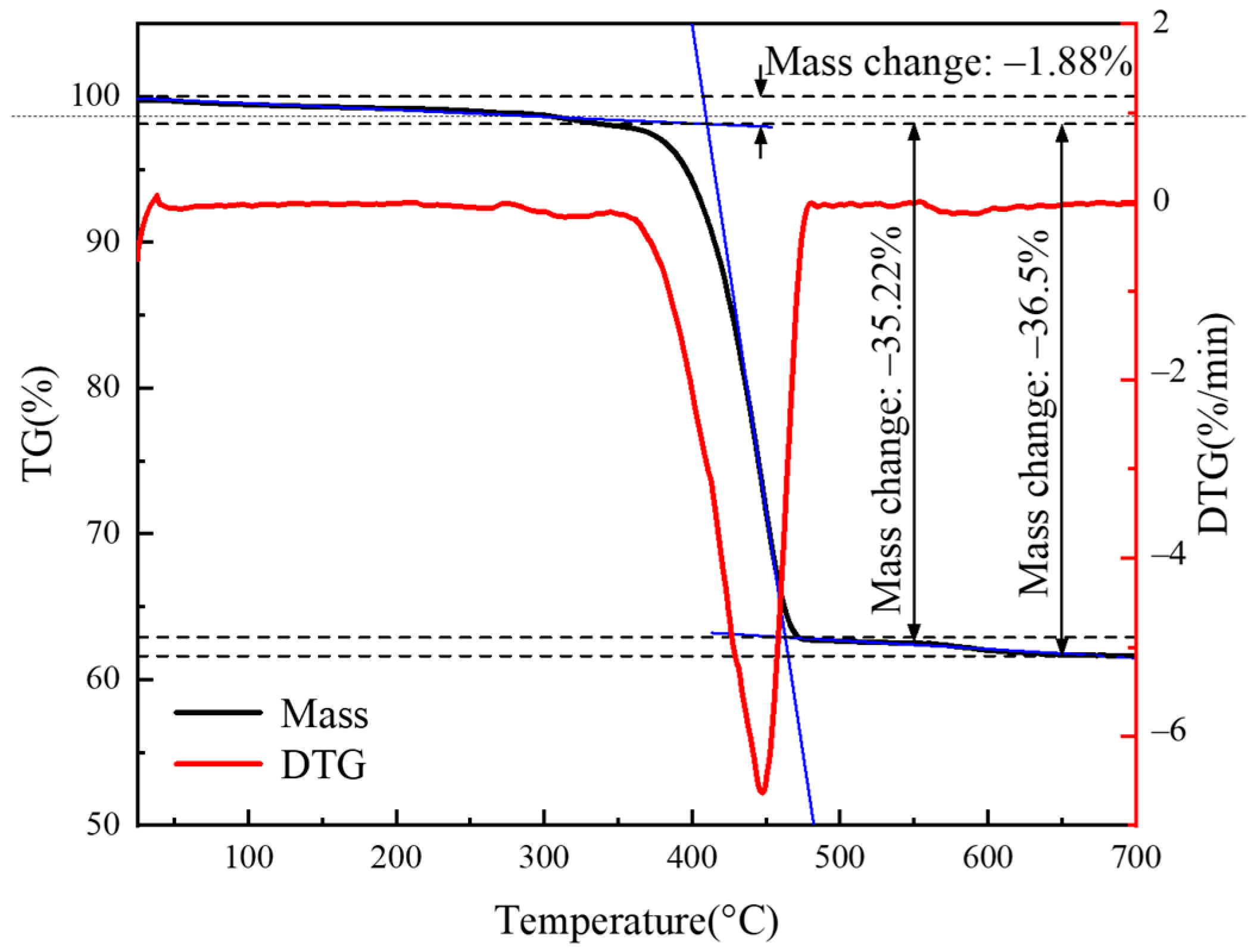
2.2. Thermal Analysis Tests
2.3. Flexural Tests
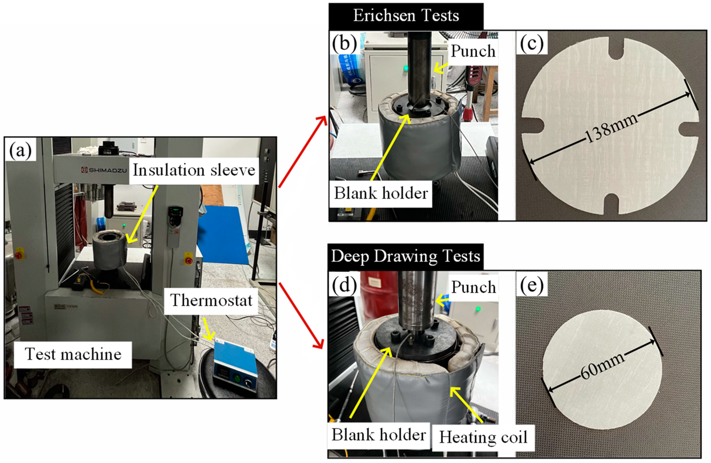
2.4. Erichsen Tests
2.5. Deep Drawing Tests
2.6. Microstructure Observation
3. Results and Discussion
3.1. Thermal Properties of CGFRPP Composites
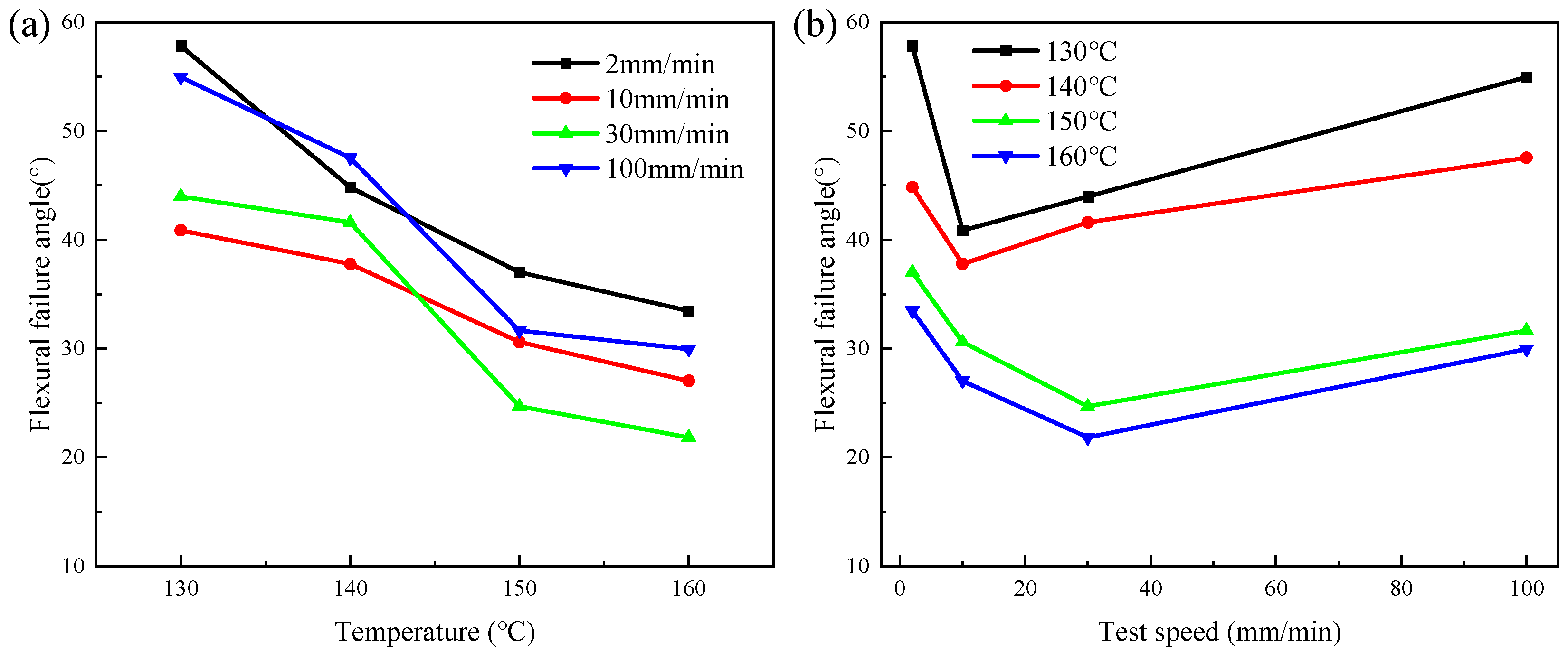
3.2. Flexural Properties and Formability under Different Parameters
3.3. Erichsen Formability under Different Parameters
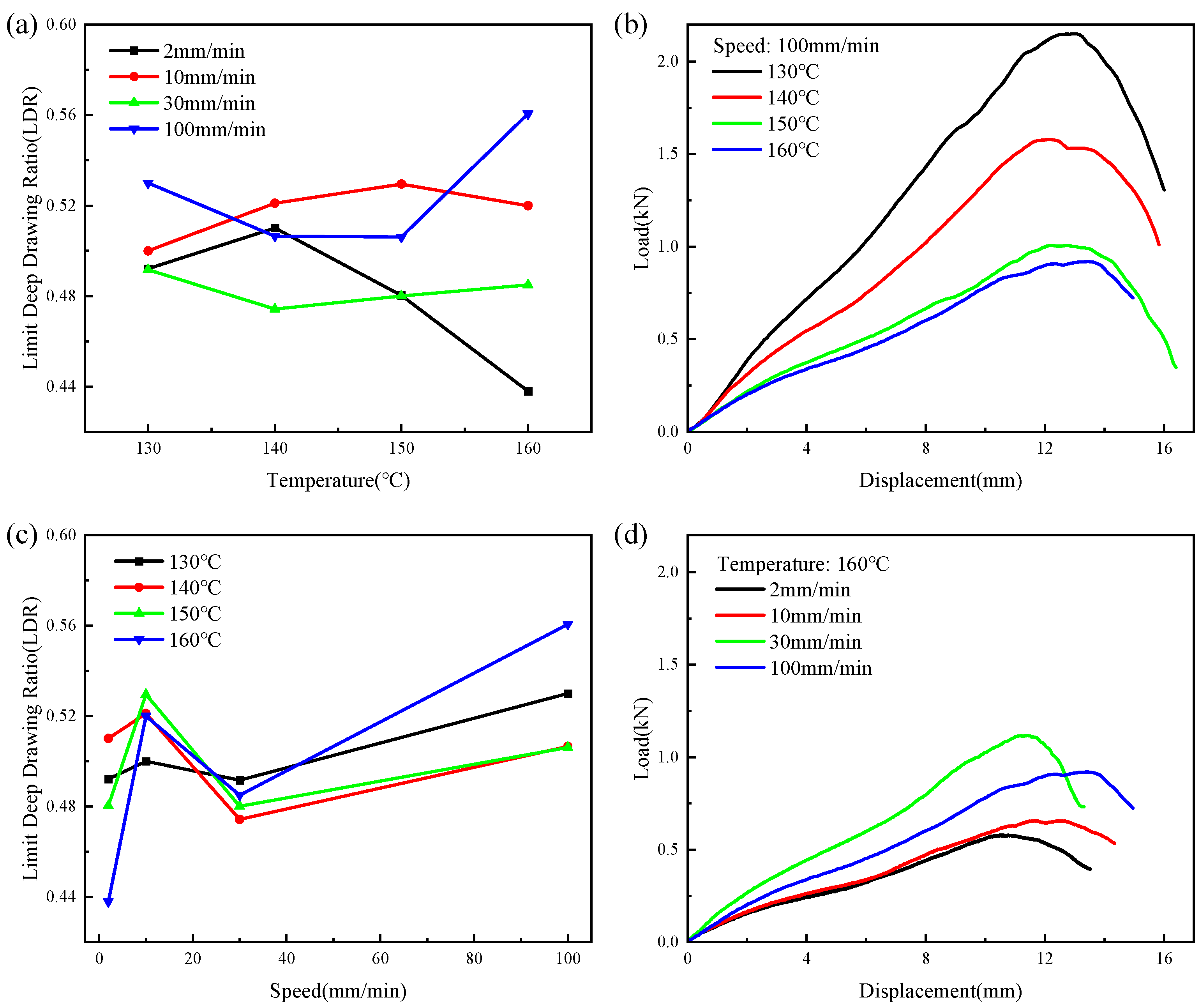
3.4. Deep Drawing Properties and Formability under Different Parameters
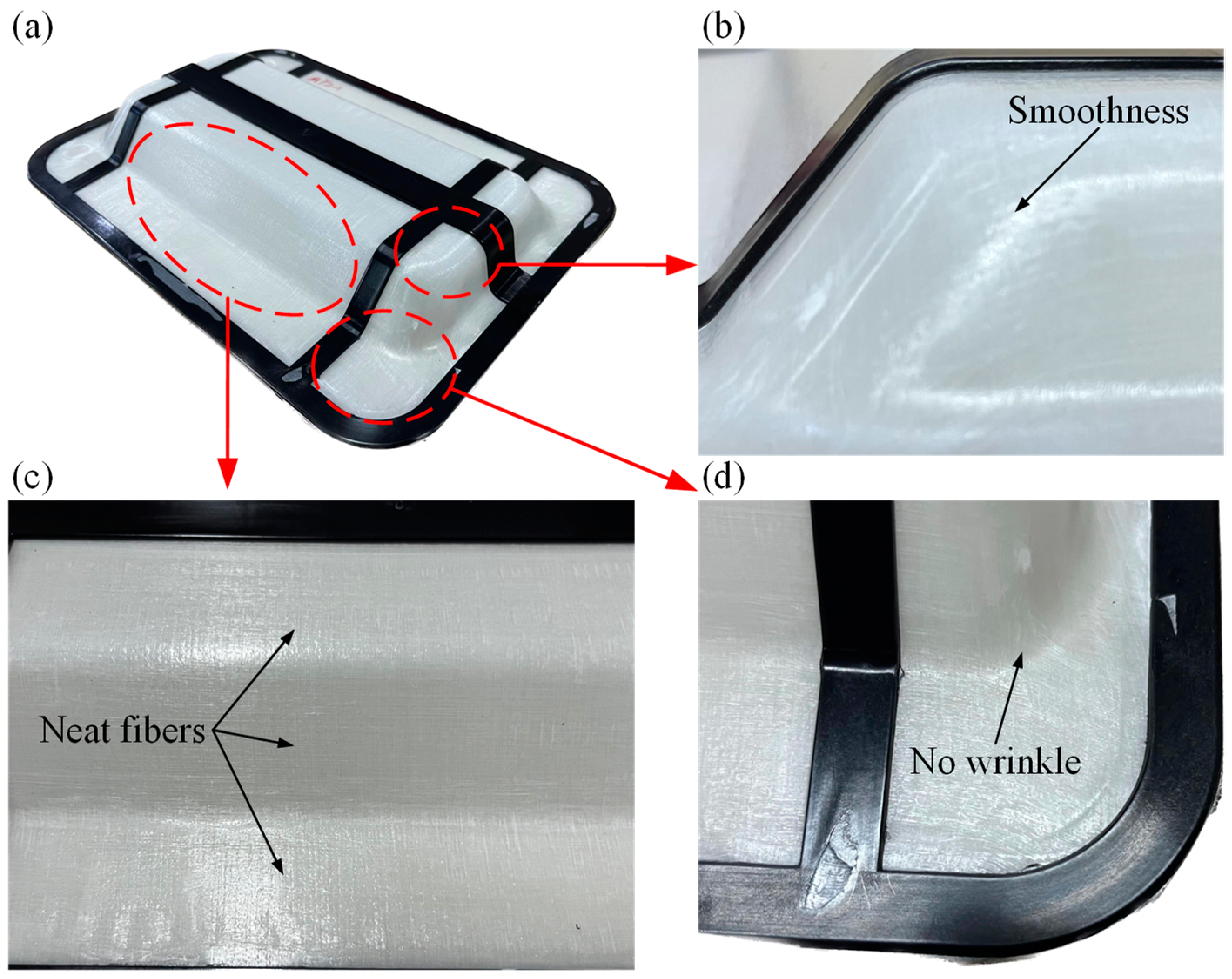
3.5. Thermoforming of CGFRPP Laminate
4. Conclusions
- (1)
- CGFRPP laminates have good thermal stability, and the quality starts to change drastically at 410 °C, which is in line with the thermal deformation condition. The optimum molding temperature range for CGFRPP laminates is 130–160 °C, and the crystallinity is 54.26%.
- (2)
- The forming limits of CGFRPP laminates at temperatures below the melting temperature were investigated using flexural tests, Erichsen tests, and deep drawing tests. The thermoforming properties of the CGFRPP laminates are affected by the deformation speed and deformation temperature. The optimal flexural properties and LER of the CGFRPP laminates occur at a deformation temperature of 130 °C and a speed of 2 mm/min. In contrast, the highest LDR is achieved at a deformation temperature of 160 °C and a speed of 100 mm/min.
- (3)
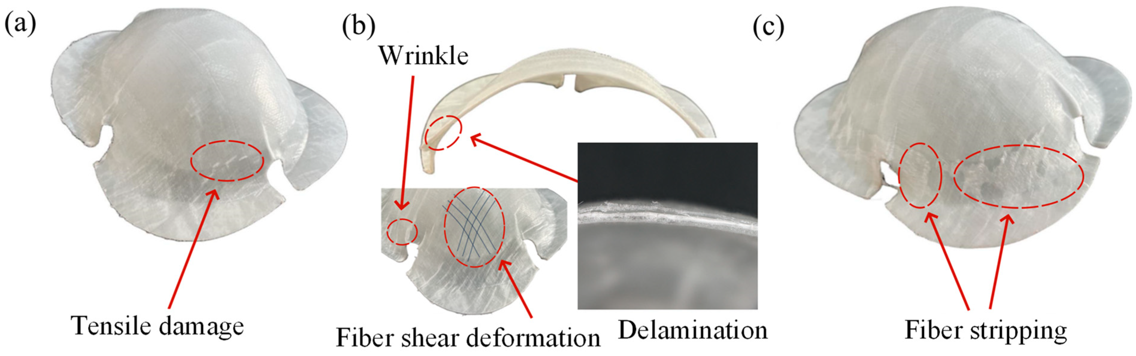
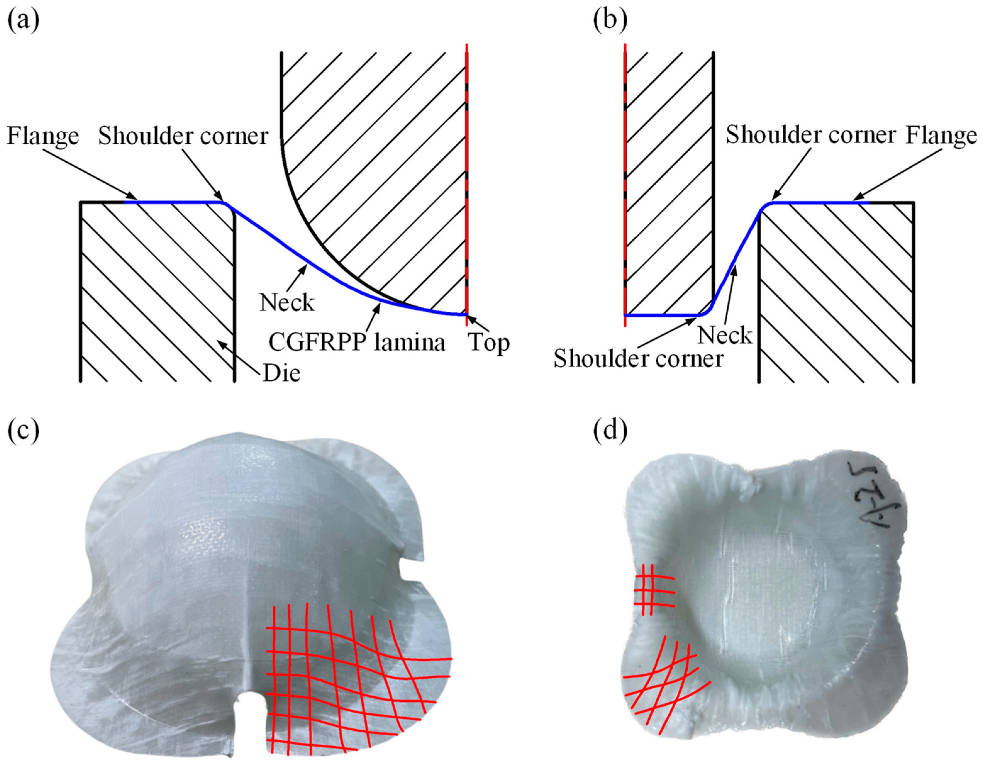
- In the deformation process, plastic deformation, shear deformation, and compression will occur in each part of CGFRPP laminates. Wrinkles and delamination tend to form at the corners and flanges. The apparent quality of CGFRPP thermoformed parts can be optimized by increasing the corner radius and adding slope.
Author Contributions
Funding
Institutional Review Board Statement
Data Availability Statement
Acknowledgments
Conflicts of Interest
References
- Pervaiz, M.; Panthapulakkal, S.; Sain, M.; Tjong, J. Emerging Trends in Automotive Lightweighting through Novel Composite Materials. Mater. Sci. Appl. 2016, 7, 26–38. [Google Scholar] [CrossRef]
- Han, S.; Guang, X.; Li, Z.; Li, Y. Joining processes of CFRP-AL sheets in automobile lightweighting technologies: A review. Polym. Compos. 2022, 43, 8622–8633. [Google Scholar] [CrossRef]
- Zhang, W.; Xu, J. Advanced lightweight materials for Automobiles: A review. Mater. Des. 2022, 221, 110994. [Google Scholar] [CrossRef]
- Musa, A.A.; Onwualu, A.P. Potential of lignocellulosic fiber reinforced polymer composites for automobile parts production: Current knowledge, research needs, and future direction. Heliyon 2024, 10, 2468. [Google Scholar] [CrossRef]
- Fu, L.; Zhang, M.; Zhai, Z.; Jiang, F. The influence of preheating temperature on the mechanical properties of injection-overmolded hybrid glass fiber reinforced thermoplastic composites. Polym. Test. 2022, 105, 107425. [Google Scholar] [CrossRef]
- Deng, T.; Huang, Z.; Chen, L.; Peng, X.; Chen, C.; Lu, x.; Zhou, H.; Zhou, H. Injection over-molding warpage prediction of continuous fiber-reinforced thermoplastic composites considering yarn reorientation. Thin-Walled Struct. 2022, 180, 109804. [Google Scholar] [CrossRef]
- Grubb, C.A.; Keffer, D.J.; Webb, C.D.; Kardos, M.; Mainka, H.; Harper, D.P. Paper fiber-reinforced polypropylene composites from nonwoven preforms: A study on compression molding optimization from a manufacturing perspective. Compos. Part A Appl. Sci. Manuf. 2024, 185, 108339. [Google Scholar] [CrossRef]
- Chen, Q.; Boisse, P.; Park, C.H.; Saouab, A.; Bréard, J. Intra/inter-ply shear behaviors of continuous fiber reinforced thermoplastic composites in thermoforming processes. Compos. Struct. 2011, 93, 1692–1703. [Google Scholar] [CrossRef]
- Brooks, R.A.; Wang, H.; Ding, Z.; Xu, J.; Song, Q.; Liu, H.; Dear, J.P.; Li, N. A review on stamp forming of continuous fibre-reinforced thermoplastics. Int. J. Lightweight Mater. Manuf. 2022, 5, 411–430. [Google Scholar] [CrossRef]
- Nakajima, K.; Matsuzaki, R. Formability of curved multilayer laminates via 3D printing using twisted continuous fiber composites. Heliyon 2023, 9, 20986. [Google Scholar] [CrossRef]
- Pipes, R.B.; Hicks, J.; Barocio, E.; Chinwicharnam, K.; Yamamoto, S. Shape compensation for carbon fiber thermoplastic composite stamp forming. Compos. Part B Eng. 2024, 282, 111577. [Google Scholar] [CrossRef]
- Bigg, D.M. Mechanical property enhancement of semicrystalline polymers—A review. Polym. Eng. Sci. 1988, 28, 830–841. [Google Scholar] [CrossRef]
- Bigg, D.M.; Preston, J.R. Stamping of thermoplastic matrix composites. Polym. Compos. 1989, 10, 261–268. [Google Scholar] [CrossRef]
- Nishino, A.; Oya, T. Multiscale analysis of the formability of CFRP sheets subjected to warm forming with a temperature-dependent epoxy model. Int. J. Mater. Form. 2019, 12, 793–800. [Google Scholar] [CrossRef]
- Zhang, Z.; Zhang, S.; Ban, X.; Zhao, X.; Ren, Z.; Han, J.; Zhang, C.; Lin, P.; Wang, T.; Wang, T. Forming limits and interface damage behavior of different acting surfaces on TA2/Q235B composite plate. Trans. Nonferrous Met. Soc. China 2024, 34, 2181–2191. [Google Scholar] [CrossRef]
- Zheng, L.; Yoon, J.W. A new failure criterion for predicting meso/micro-scale forming limit of composite metal foils. Int. J. Plast. 2024, 176, 103962. [Google Scholar] [CrossRef]
- Uriya, Y.; Yanagimoto, J. Suitable structure of thermosetting CFRP sheet for cold/warm forming. Int. J. Mater. Form. 2016, 9, 243–252. [Google Scholar] [CrossRef]
- Uriya, Y.; Yanagimoto, J. Bore-expanding test for thermosetting carbon-fiber-reinforced plastic sheets. Int. J. Mater. Form. 2017, 10, 823–829. [Google Scholar] [CrossRef]
- Uriya, Y.; Ikeuchi, K.; Yanagimoto, J. Enhanced formability of thin carbon fiber reinforced plastic sheets in cold/warm embossing with ductile dummy sheets of different thicknesses. Int. J. Mater. Form. 2015, 8, 415–421. [Google Scholar] [CrossRef]
- Uriya, Y.; Yanagimoto, J. Erichsen cupping test on thermosetting CFRP sheets. Int. J. Mater. Form. 2017, 10, 527–534. [Google Scholar] [CrossRef]
- Zheng, B.; Gao, X.; Li, M.; Deng, T.; Huang, Z.; Zhou, H.; Li, D. Formability and Failure Mechanisms of Woven CF/PEEK Composite Sheet in Solid-State Thermoforming. Polymers 2019, 11, 966. [Google Scholar] [CrossRef] [PubMed]
- Zhao, F.; Guo, W.; Li, W.; Mao, H.; Yan, H.; Deng, J. A Study on Hot Stamping Formability of Continuous Glass Fiber Reinforced Thermoplastic Composites. Polymers 2022, 14, 4935. [Google Scholar] [CrossRef] [PubMed]
- Takuda, H.; Enami, T.; Kubota, K.; Hatta, N. The formability of a thin sheet of Mg–8.5 Li–1Zn alloy. J. Mater. Process. Technol. 2000, 101, 281–286. [Google Scholar] [CrossRef]
- Zhang, Q.; Gao, Q.; Cai, J. Experimental and simulation research on thermal stamping of carbon fiber composite sheet. Trans. Nonferrous Met. Soc. China 2014, 24, 217–223. [Google Scholar] [CrossRef]
- Vieille, B.; Albouy, W.; Taleb, L. Investigations on stamping of C/PEEK laminates: Influence on meso-structure and macroscopic mechanical properties under severe environmental conditions. Compos. Part B Eng. 2014, 63, 101–110. [Google Scholar] [CrossRef]
- Nikforooz, M.; Montesano, J.; Golzar, M.; Shokrieh, M.M. Assessment of the thermomechanical performance of continuous glass fiber-reinforced thermoplastic laminates. Polym. Test. 2018, 67, 457–467. [Google Scholar] [CrossRef]
- Tomlin, L.J.; Cender, T.A.; Sauerbrunn, S.; Adcani, S.G. Methodology to establish a forming process window for thermoset aligned discontinuous fiber composites. Compos. Part A Appl. Sci. Manuf. 2024, 180, 108064. [Google Scholar] [CrossRef]
- Ou, Y.; Zhu, D. Tensile behavior of glass fiber reinforced composite at different strain rates and temperatures. Constr. Build. Mater. 2015, 96, 648–656. [Google Scholar] [CrossRef]
- Wang, W.; Zhang, X.; Chouw, N.; Li, Z.; Shi, Y. Strain rate effect on the dynamic tensile behaviour of flax fibre reinforced polymer. Compos. Struct. 2018, 200, 135–143. [Google Scholar] [CrossRef]
- Bai, R.; Guzman-Maldonado, E.; Zheng, R.; Colmars, J. Influence of in-plane bending behaviour on textile composite reinforcement forming. Int. J. Mech. Sci. 2024, 273, 109206. [Google Scholar] [CrossRef]
- Tan, L.B.; Teo, W.S.; Cheah, Y.W.; Narayanaswamy, S. A Modeling Framework for the Thermoforming of Carbon Fiber Reinforced Thermoplastic Composites. Polymers 2024, 16, 2186. [Google Scholar] [CrossRef] [PubMed]


| Experiment | Value | Unit |
|---|---|---|
| Temperature | 130, 140, 150, 160 | °C |
| Speed | 2, 10, 30, 100 | mm/min |
| Blanking Torque | 10 | N·m |
| /°C·min−1 | /°C | /°C | /J·g−1 | /% |
|---|---|---|---|---|
| 5 | 165.39 | 131.44 | 38.76 | 48.32 |
| 10 | 164.79 | 127.88 | 41.04 | 51.16 |
| 15 | 164.15 | 125.21 | 37.64 | 46.92 |
| 20 | 164.00 | 123.71 | 39.87 | 49.70 |
| Material values | 164.58 | 127.06 | 39.33 | 49.03 |
Disclaimer/Publisher’s Note: The statements, opinions and data contained in all publications are solely those of the individual author(s) and contributor(s) and not of MDPI and/or the editor(s). MDPI and/or the editor(s) disclaim responsibility for any injury to people or property resulting from any ideas, methods, instructions or products referred to in the content. |
© 2024 by the authors. Licensee MDPI, Basel, Switzerland. This article is an open access article distributed under the terms and conditions of the Creative Commons Attribution (CC BY) license (https://creativecommons.org/licenses/by/4.0/).
Share and Cite
Ying, Q.; Jia, Z.; Rong, D.; Liu, L.; Li, J. Formability and Failure Mechanisms of Continuous Glass Fiber-Reinforced Polypropylene Composite Laminates in Thermoforming Below the Melting Temperature. Polymers 2024, 16, 2885. https://doi.org/10.3390/polym16202885
Ying Q, Jia Z, Rong D, Liu L, Li J. Formability and Failure Mechanisms of Continuous Glass Fiber-Reinforced Polypropylene Composite Laminates in Thermoforming Below the Melting Temperature. Polymers. 2024; 16(20):2885. https://doi.org/10.3390/polym16202885
Chicago/Turabian StyleYing, Qihui, Zhixin Jia, Di Rong, Lijun Liu, and Jiqiang Li. 2024. "Formability and Failure Mechanisms of Continuous Glass Fiber-Reinforced Polypropylene Composite Laminates in Thermoforming Below the Melting Temperature" Polymers 16, no. 20: 2885. https://doi.org/10.3390/polym16202885
APA StyleYing, Q., Jia, Z., Rong, D., Liu, L., & Li, J. (2024). Formability and Failure Mechanisms of Continuous Glass Fiber-Reinforced Polypropylene Composite Laminates in Thermoforming Below the Melting Temperature. Polymers, 16(20), 2885. https://doi.org/10.3390/polym16202885