
Enhancing Amplification in Compliant Mechanisms: Optimization of Plastic Types and Injection Conditions
 ,
,
Abstract
:1. Introduction
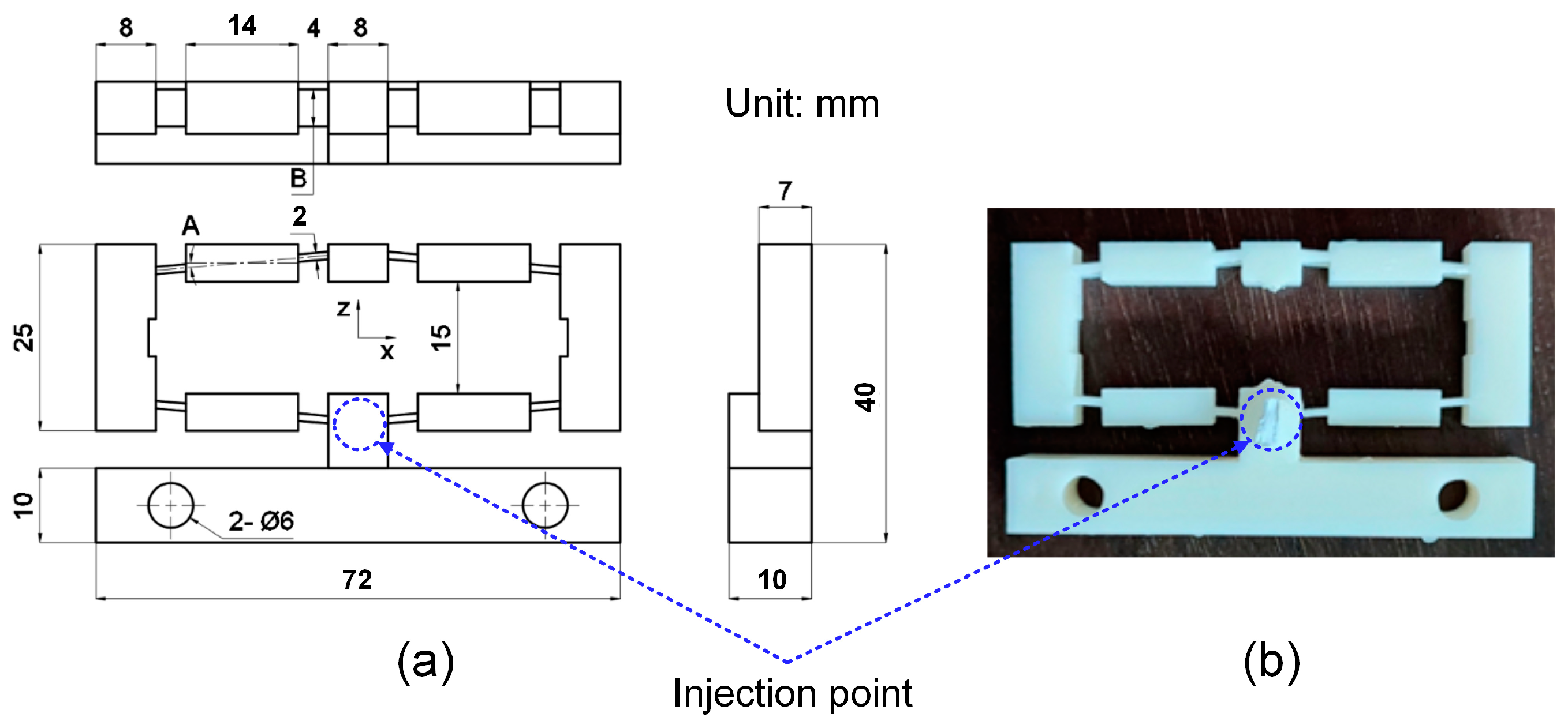
2. Experimental Methods
3. Results and Discussion
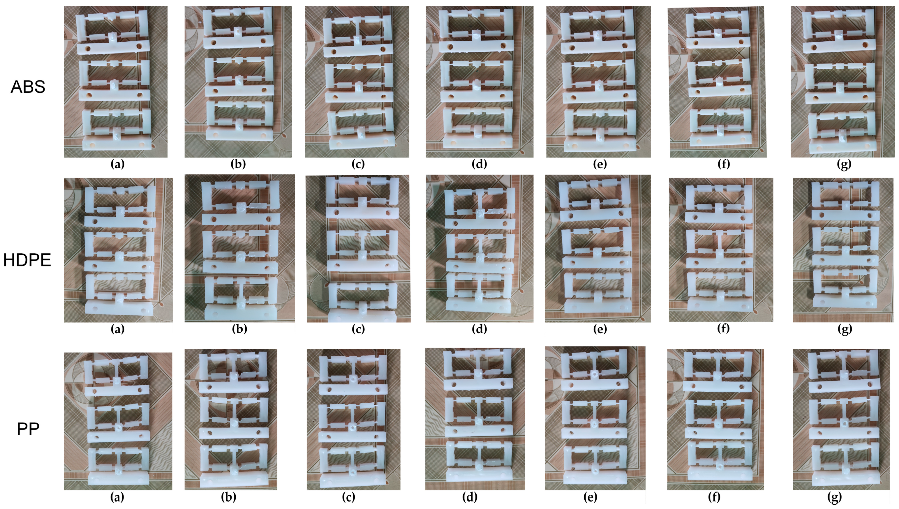
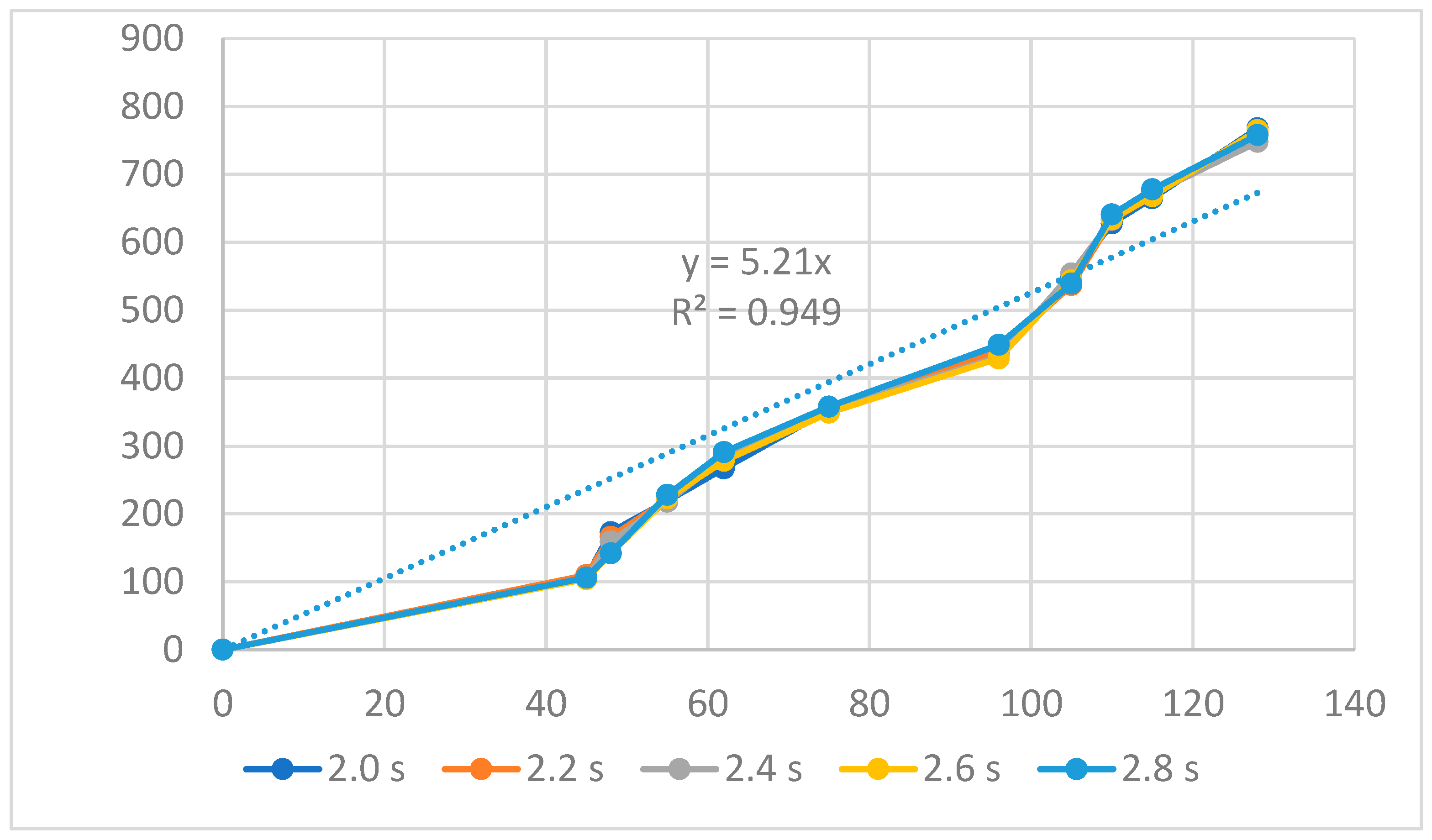
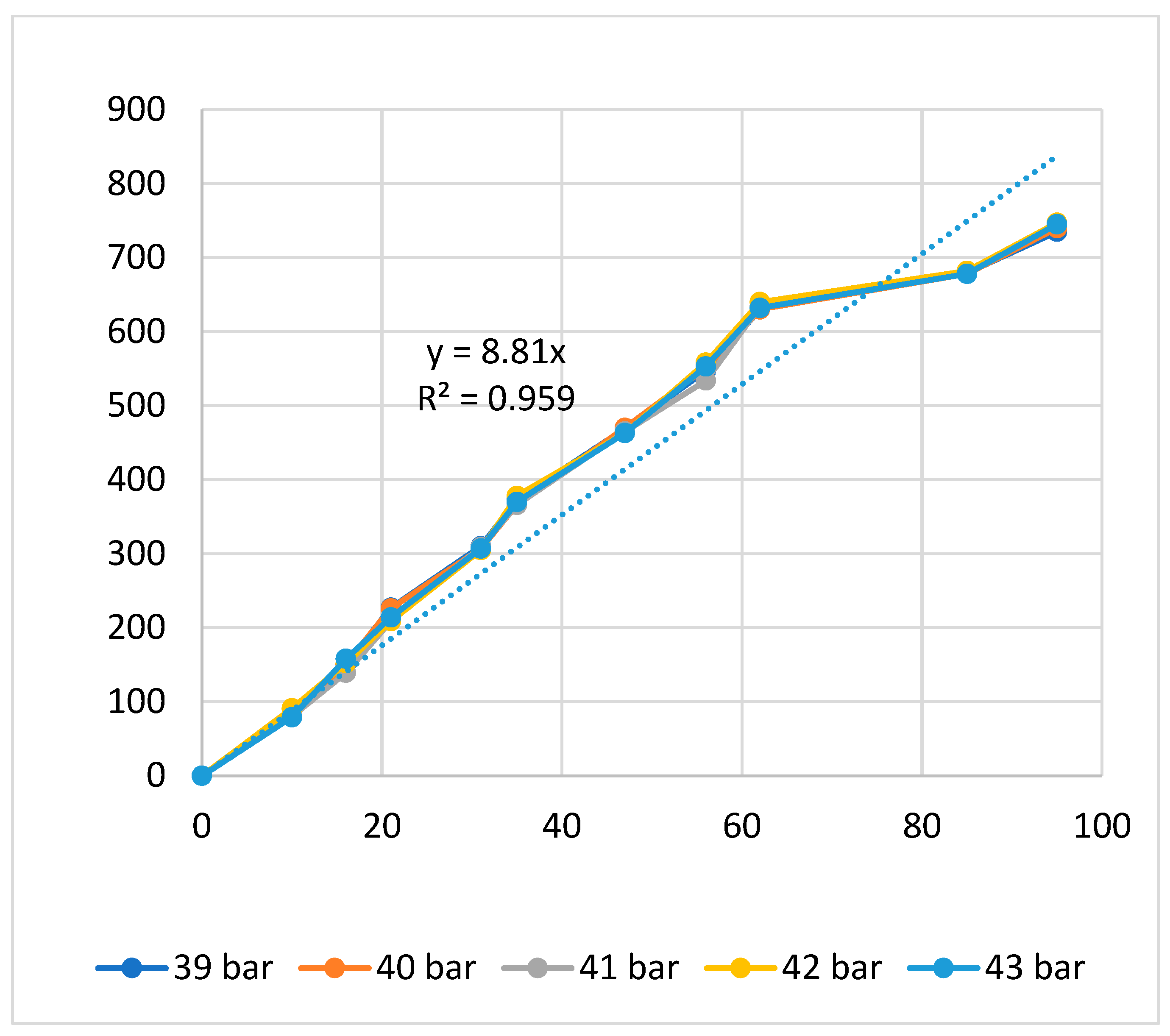
3.1. ABS Flexure Hinge
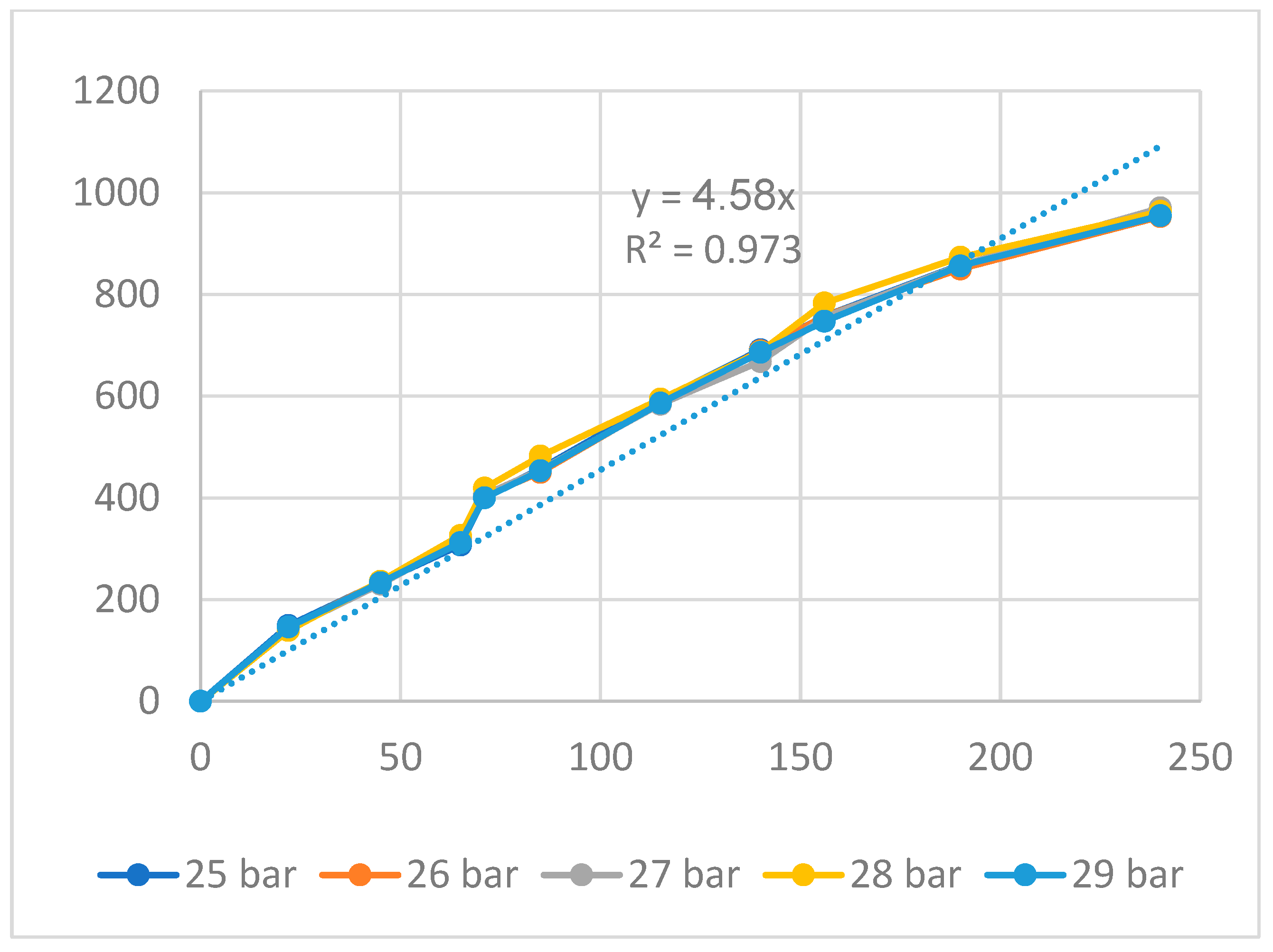
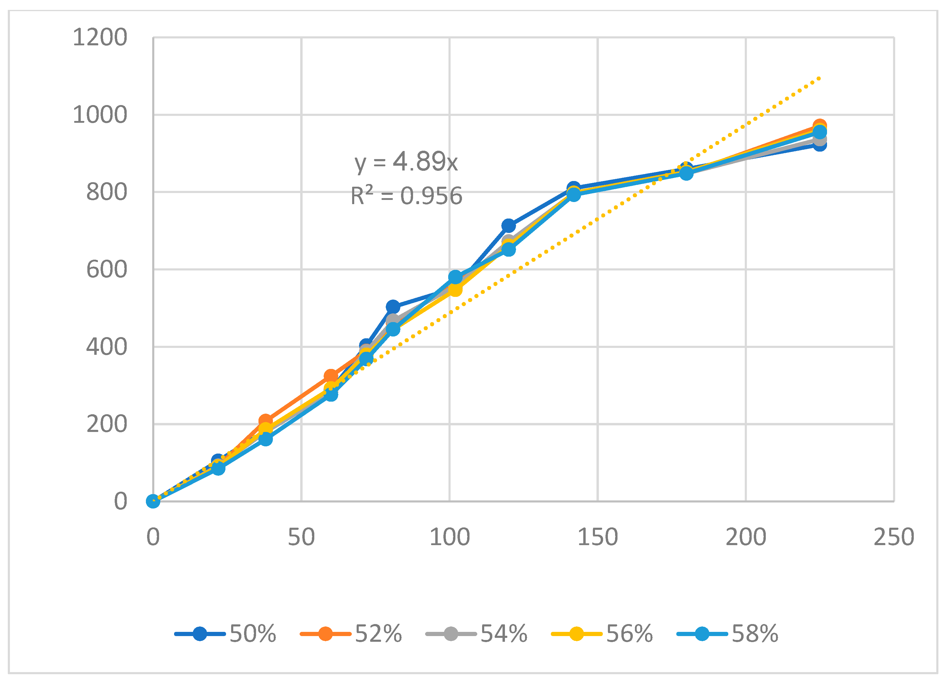
3.2. PP Flexure Hinge
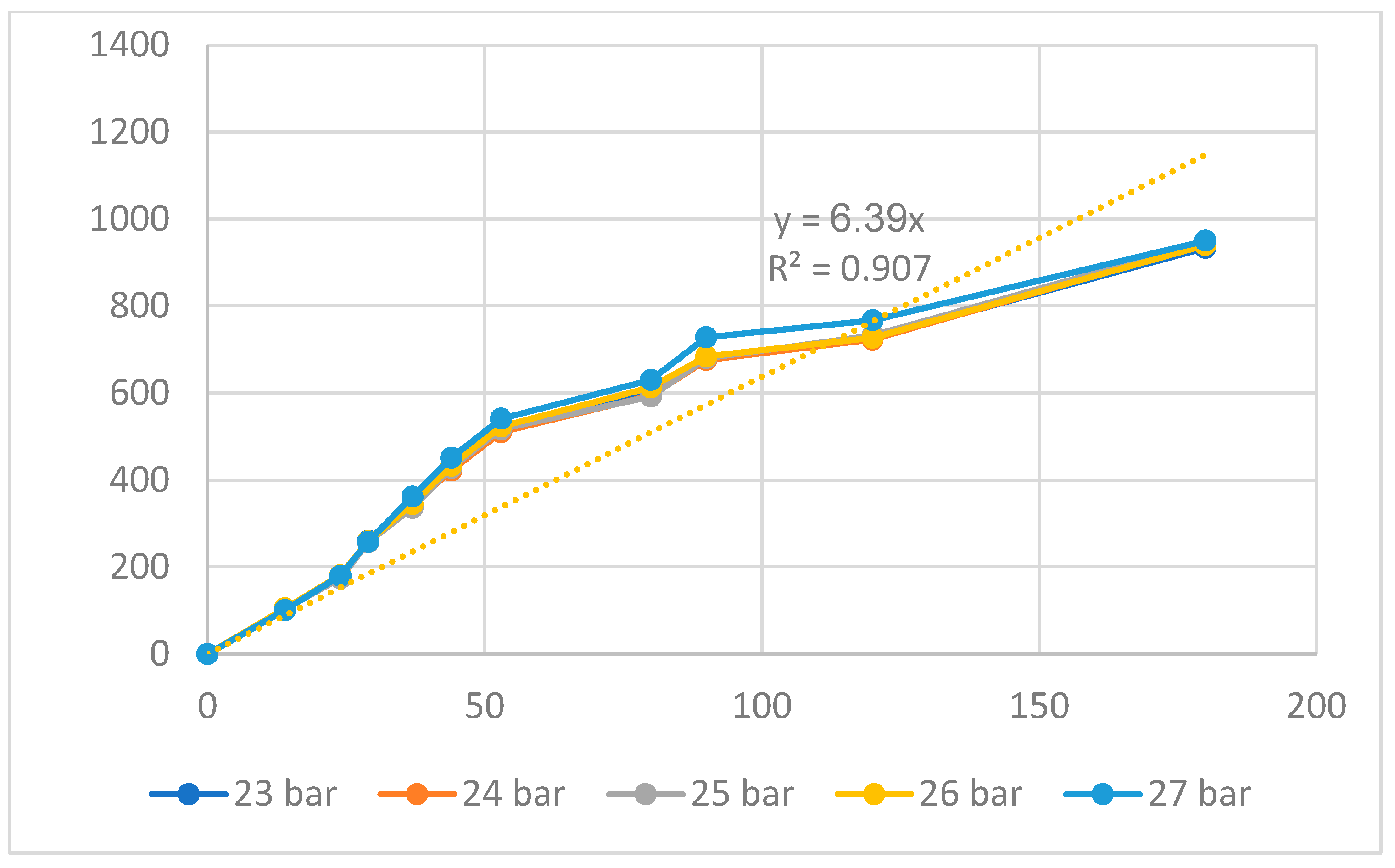
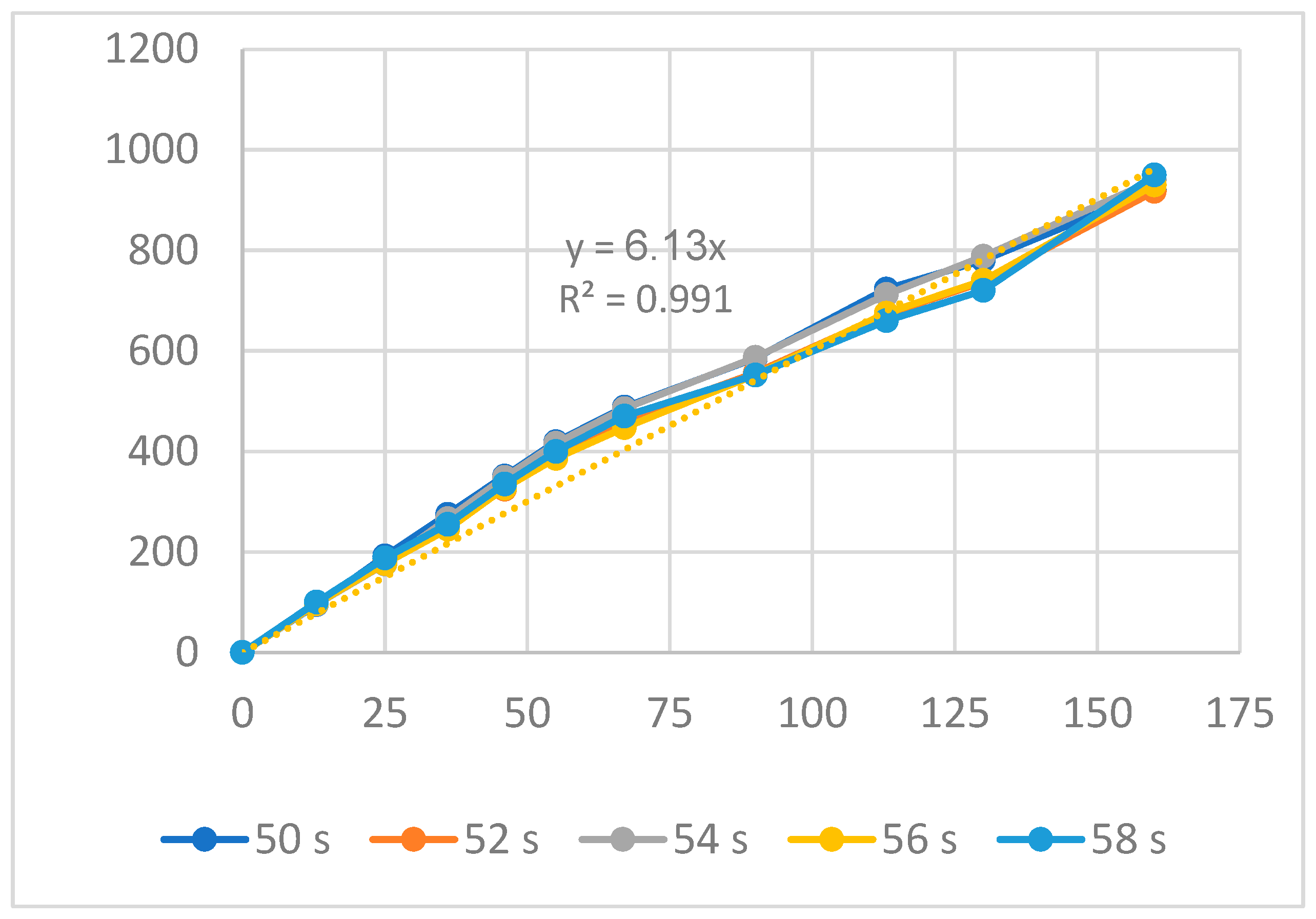
3.3. HDPE Flexure Hinge and Comparison
4. Conclusions
Author Contributions
Funding
Institutional Review Board Statement
Informed Consent Statement
Data Availability Statement
Acknowledgments
Conflicts of Interest
References
- Tian, Y.; Zhang, D.; Shirinzadeh, B. Dynamic modelling of a flexure-based mechanism for ultra-precision grinding operation. Precis. Eng. 2011, 35, 554–565. [Google Scholar] [CrossRef]
- Gao, X.; Yang, J.; Wu, J.; Xin, X.; Li, Z.; Yuan, X.; Shen, X.; Dong, S. Piezoelectric actuators and motors: Materials, designs, and applications. Adv. Mater. Technol. 2020, 5, 1900716. [Google Scholar] [CrossRef]
- Chen, F.; Zhang, Q.; Gao, Y.; Dong, W. A review on the flexure-based displacement amplification mechanisms. IEEE Access 2020, 8, 205919–205937. [Google Scholar] [CrossRef]
- Mutlu, R.; Tawk, C.; Alici, G.; Sariyildiz, E. A 3D printed monolithic soft gripper with adjustable stiffness. In Proceedings of the IECON 2017-43rd Annual Conference of the IEEE Industrial Electronics Society, Beijing, China, 29 October–1 November 2017; pp. 6235–6240. [Google Scholar]
- Judy, J.W. Microelectromechanical systems (MEMS): Fabrication, design and applications. Smart Mater. Struct. 2001, 10, 1115. [Google Scholar] [CrossRef]
- Shaar, N.S.; Barbastathis, G.; Livermore, C. Integrated folding, alignment, and latching for reconfigurable origami microelectromechanical systems. J. Microelectromech. Syst. 2014, 24, 1043–1051. [Google Scholar] [CrossRef]
- Bagolini, A.; Ronchin, S.; Bellutti, P.; Chistè, M.; Verotti, M.; Belfiore, N.P. Fabrication of novel MEMS microgrippers by deep reactive ion etching with metal hard mask. J. Microelectromech. Syst. 2017, 26, 926–934. [Google Scholar] [CrossRef]
- Solgaard, O.; Godil, A.A.; Howe, R.T.; Lee, L.P.; Peter, Y.A.; Zappe, H. Optical MEMS: From micromirrors to complex systems. J. Microelectromech. Syst. 2014, 23, 517–538. [Google Scholar] [CrossRef]
- Noveanu, S.; Lates, D.; Fusaru, L.; Rusu, C. A new compliant microgripper and study for flexure hinges shapes. Procedia Manuf. 2020, 46, 517–524. [Google Scholar] [CrossRef]
- Hinkley, D.; Simburger, E. A multifunctional flexure hinge for deploying omnidirectional solar arrays. In Proceedings of the 19th AIAA Applied Aerodynamics Conference, Anaheim, CA, USA, 11–14 June 2001; p. 1260. [Google Scholar]
- Marsh, D.M. The construction and performance of various flexure hinges. J. Sci. Instrum. 1962, 39, 493. [Google Scholar] [CrossRef]
- Smith, S.T.; Badami, V.G.; Dale, J.S.; Xu, Y. Elliptical flexure hinges. Rev. Sci. Instrum. 1997, 68, 1474–1483. [Google Scholar] [CrossRef]
- Wei, H.; Shirinzadeh, B.; Niu, X.; Zhang, J.; Li, W.; Simeone, A. Study of the hinge thickness deviation for a 316L parallelogram flexure mechanism fabricated via selective laser melting. J. Intell. Manuf. 2021, 32, 1411–1420. [Google Scholar] [CrossRef]
- Coemert, S.; Wegener, L.G.; Yalvac, B.; Fuckner, J.; Lueth, T.C. Experimental and FEM-Based Payload Analysis of Ti-6Al-4V Flexure Hinges. In Proceedings of the ASME International Mechanical Engineering Congress and Exposition, Salt Lake City, UT, USA, 11–14 November 2019; Volume 83518, p. V014T14A001. [Google Scholar]
- Roopa, R.; Karanth, P.N.; Kulkarni, S.M. Effect of flexure beam geometry and material on the displacement of piezo actuated diaphragm for micropump. In IOP Conference Series: Materials Science and Engineering; IOP Publishing: Bristol, UK, 2018; Volume 310, p. 012111. [Google Scholar]
- Schlick, J.; Zuehlke, D. Design and application of a gripper for microparts using flexure hinges and pneumatic actuation. In Microrobotics and Microassembly III; SPIE: Bellingham, DC, USA, 2001; Volume 4568, pp. 1–11. [Google Scholar]
- Mutlu, R.; Alici, G.; in het Panhuis, M.; Spinks, G. Effect of flexure hinge type on a 3D printed fully compliant prosthetic finger. In Proceedings of the 2015 IEEE International Conference on Advanced Intelligent Mechatronics (AIM), Busan, Republic of Korea, 7–11 July 2015; pp. 790–795. [Google Scholar]
- Rosa, F.; Scaccabarozzi, D.; Cinquemani, S.; Bizzozero, F. Sensor Embedding in a 3D Printed Flexure Hinge. In Design Tools and Methods in Industrial Engineering, Proceedings of the International Conference on Design Tools and Methods in Industrial Engineering, ADM 2019, Modena, Italy, 9–10 September 2019; Springer International Publishing: Berlin/Heidelberg, Germany, 2020; pp. 848–859. [Google Scholar]
- Sahota, J.K.; Dhawan, D.; Gupta, N. Modeling and Analysis of Temperature-Compensated Fiber Bragg Grating Sensor Based on Flexure Hinge Beam and Diaphragm for Low-Pressure Detection. Arab. J. Sci. Eng. 2023, 49, 1095–1115. [Google Scholar] [CrossRef]
- Shen, X.; Zhang, L.; Qiu, D. A lever-bridge combined compliant mechanism for translation amplification. Precis. Eng. 2021, 67, 383–392. [Google Scholar] [CrossRef]
- Abedi, K.; Shakhesi, E.; Seraj, H.; Mahnama, M.; Shirazi, F.A. Design and analysis of a 2-DOF compliant serial micropositioner based on “S-shaped” flexure hinge. Precis. Eng. 2023, 83, 228–236. [Google Scholar] [CrossRef]
- Shi, C.; Dong, X.; Yang, Z. A microgripper with a large magnification ratio and high structural stiffness based on a flexure-enabled mechanism. IEEE/ASME Trans. Mechatron. 2021, 26, 3076–3086. [Google Scholar] [CrossRef]
- Chen, X.; Li, Y. Design, modeling and testing of a vibration absorption device with energy harvesting based on force amplifier and piezoelectric stack. Energy Convers. Manag. 2022, 255, 115305. [Google Scholar] [CrossRef]
- Wan, L.; Chen, H.; Ouyang, L.; Chen, Y. A new ensemble modeling approach for reliability-based design optimization of flexure-based bridge-type amplification mechanisms. Int. J. Adv. Manuf. Technol. 2020, 106, 47–63. [Google Scholar] [CrossRef]
- McCormick, R.M.; Nelson, R.J.; Alonso-Amigo, M.G.; Benvegnu, D.J.; Hooper, H.H. Microchannel electrophoretic separations of DNA in injection-molded plastic substrates. Anal. Chem. 1997, 69, 2626–2630. [Google Scholar] [CrossRef] [PubMed]
- Yu, L.; Koh, C.G.; Lee, L.J.; Koelling, K.W.; Madou, M.J. Experimental investigation and numerical simulation of injection molding with micro-features. Polym. Eng. Sci. 2002, 42, 871–888. [Google Scholar] [CrossRef]
- Agrawal, A.R.; Pandelidis, I.O.; Pecht, M. Injection-molding process control—A review. Polym. Eng. Sci. 1987, 27, 1345–1357. [Google Scholar] [CrossRef]
- Chen, Z.; Turng, L.S. A review of current developments in process and quality control for injection molding. Adv. Polym. Technol. J. Polym. Process. Inst. 2005, 24, 165–182. [Google Scholar] [CrossRef]
- Czepiel, M.; Bańkosz, M.; Sobczak-Kupiec, A. Advanced Injection Molding Methods. Materials 2023, 16, 5802. [Google Scholar] [CrossRef] [PubMed]
- Yang, W.; Jian, R. Polymer 3D Printing and 3D Copying Processes. In Polymer 3D Printing and 3D Copying Technology; Springer Nature: Singapore, 2023; pp. 17–82. [Google Scholar]
- Raju, A.; Samanta, D.; Rajendrakumar, K. A Review of Recent Advances in the Development of Superhydrophobicity over Various Substrate Surfaces Using Polymers. ChemistrySelect 2023, 8, e202204262. [Google Scholar] [CrossRef]
- Begum, S.A.; Rane, A.V.; Kanny, K. Applications of compatibilized polymer blends in automobile industry. In Compatibilization of Polymer Blends; Elsevier: Amsterdam, The Netherlands, 2020; pp. 563–593. [Google Scholar]
- Goodship, V. Injection molding of thermoplastics. In Design and Manufacture of Plastic Components for Multifunctionality: Structural Composites, Injection Molding, and 3D Printing; Elsevier: Amsterdam, The Netherlands, 2015; p. 103. [Google Scholar]
- Strapasson, R.; Amico, S.C.; Pereira, M.F.R.; Sydenstricker, T.H.D. Tensile and impact behavior of polypropylene/low density polyethylene blends. Polym. Test. 2005, 24, 468–473. [Google Scholar] [CrossRef]
- Ozcelik, B.; Ozbay, A.; Demirbas, E. Influence of injection parameters and mold materials on mechanical properties of ABS in plastic injection molding. Int. Commun. Heat Mass Transf. 2010, 37, 1359–1365. [Google Scholar] [CrossRef]
- Uyen, T.M.T.; Minh, P.S.; Nguyen, V.-T.; Do, T.T.; Nguyen Le Dang, H.; Nguyen, V.T.T. Amplification Ratio of a Recycled Plastics-Compliant Mechanism Flexure Hinge. Appl. Sci. 2023, 13, 12825. [Google Scholar] [CrossRef]
- Kim, J.H.; Kim, S.H.; Kwak, Y.K. Development and optimization of 3-D bridge-type hinge mechanisms. Sens. Actuators A Phys. 2004, 116, 530–538. [Google Scholar] [CrossRef]
- Na, T.W.; Choi, J.H.; Jung, J.Y.; Kim, H.G.; Han, J.H.; Park, K.C.; Oh, I.K. Compact piezoelectric tripod manipulator based on a reverse bridge-type amplification mechanism. Smart Mater. Struct. 2016, 25, 095028. [Google Scholar] [CrossRef]
- Ravisankar, H.; Hariprasadarao, P.; Das, V.C.; Bhanukiran, G. Effect of nanoclay inclusion on mechanical and fatigue behavior of ABS/PP/HDPE thermoplastics. Mater. Today Proc. 2020, 24, 209–217. [Google Scholar] [CrossRef]
- Maffiodo, D.; Raparelli, T. Three-fingered gripper with flexure hinges actuated by shape memory alloy wires. Int. J. Autom. Technol. 2017, 11, 355–360. [Google Scholar] [CrossRef]
- Fiaz, H.S.; Settle, C.R.; Hoshino, K. Metal additive manufacturing for microelectromechanical systems: Titanium alloy (Ti-6Al-4V)-based nanopositioning flexure fabricated by electron beam melting. Sens. Actuators A Phys. 2016, 249, 284–293. [Google Scholar] [CrossRef]


| Group | Filling Time (s) | Filling Pressure (bar) | Packing Time (s) | Packing Pressure (bar) | Cooling Time (s) | Melt Temperature (°C) | Filling Speed (%) |
|---|---|---|---|---|---|---|---|
| 2 | |||||||
| 2.2 | |||||||
| 1 | 2.4 | ||||||
| 2.6 | 41 | 0.6 | 40 | 24 | 210 | 79 | |
| 2.8 | |||||||
| 39 | |||||||
| 40 | |||||||
| 41 | |||||||
| 2 | 2.4 | 42 | 0.6 | 40 | 24 | 210 | 79 |
| 43 | |||||||
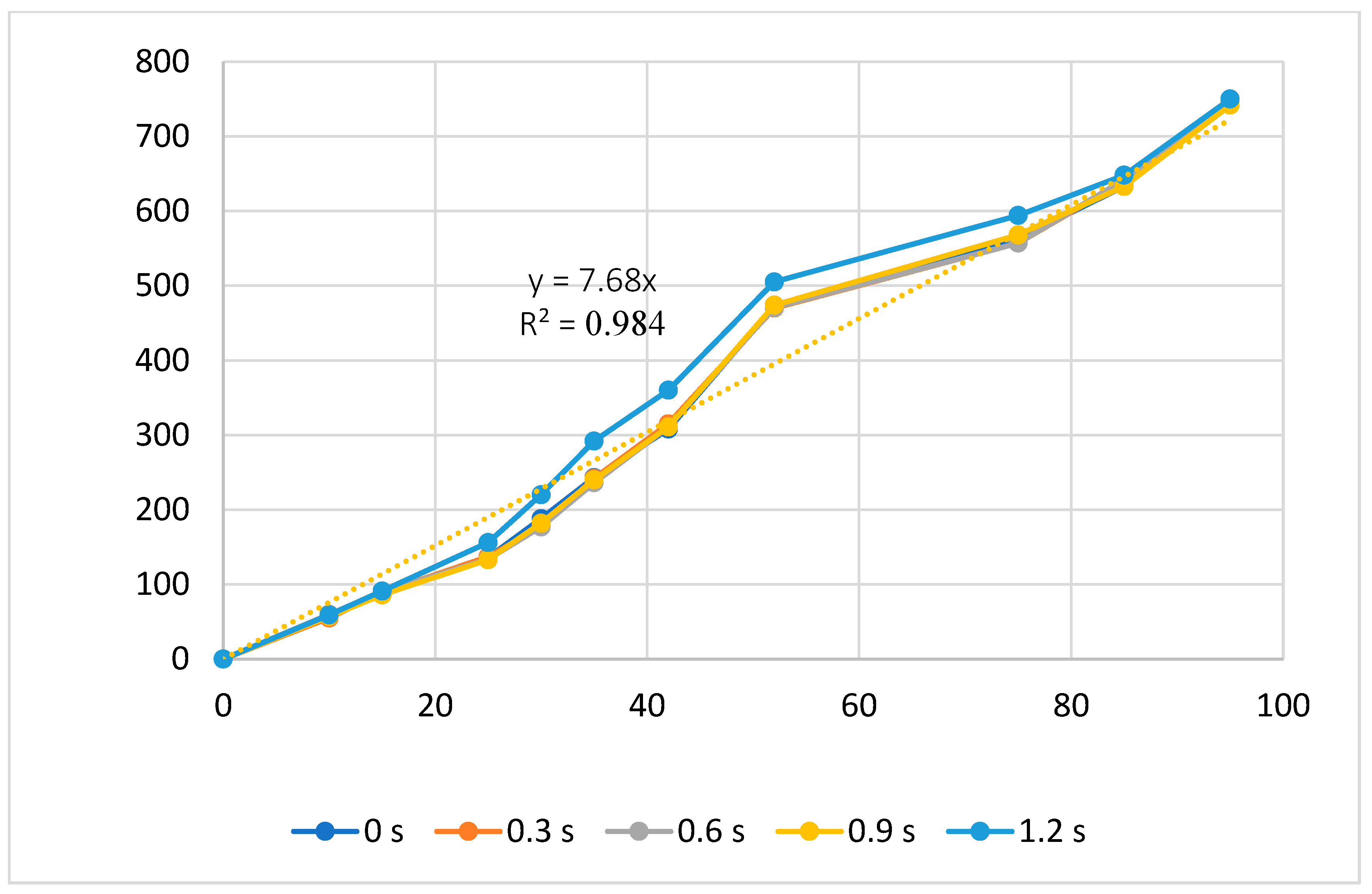
| 0 | |||||||
| 0.3 | |||||||
| 0.6 | |||||||
| 3 | 2.4 | 41 | 0.9 | 40 | 24 | 210 | 79 |
| 1.2 | |||||||
| 38 | |||||||
| 39 | |||||||
| 40 | |||||||
| 4 | 2.4 | 41 | 0.6 | 41 | 24 | 210 | 79 |
| 42 | |||||||
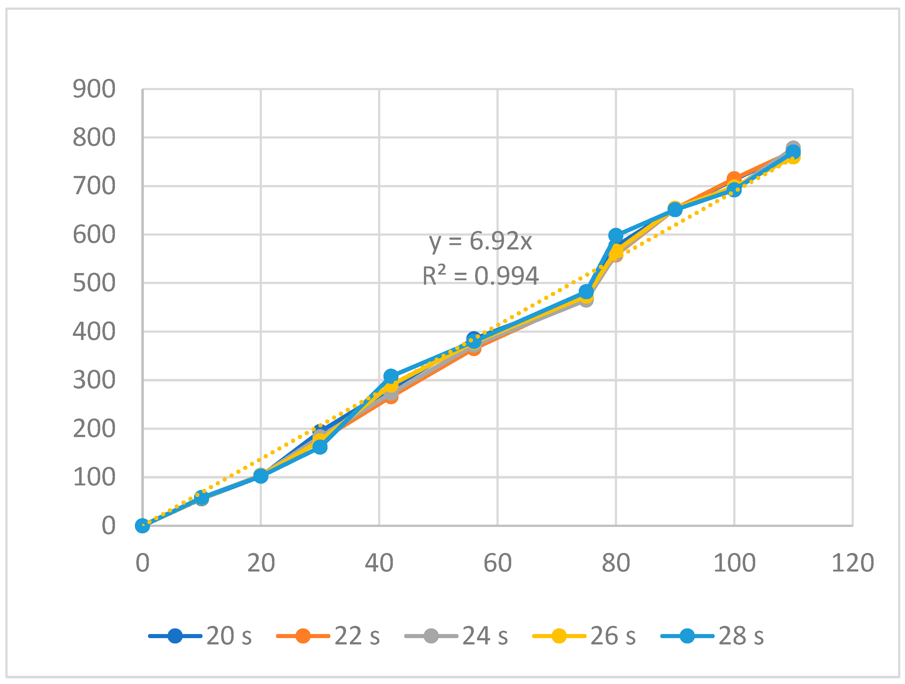
| 20 | |||||||
| 22 | |||||||
| 24 | |||||||
| 5 | 2.4 | 41 | 0.6 | 40 | 26 | 210 | 79 |
| 28 | |||||||
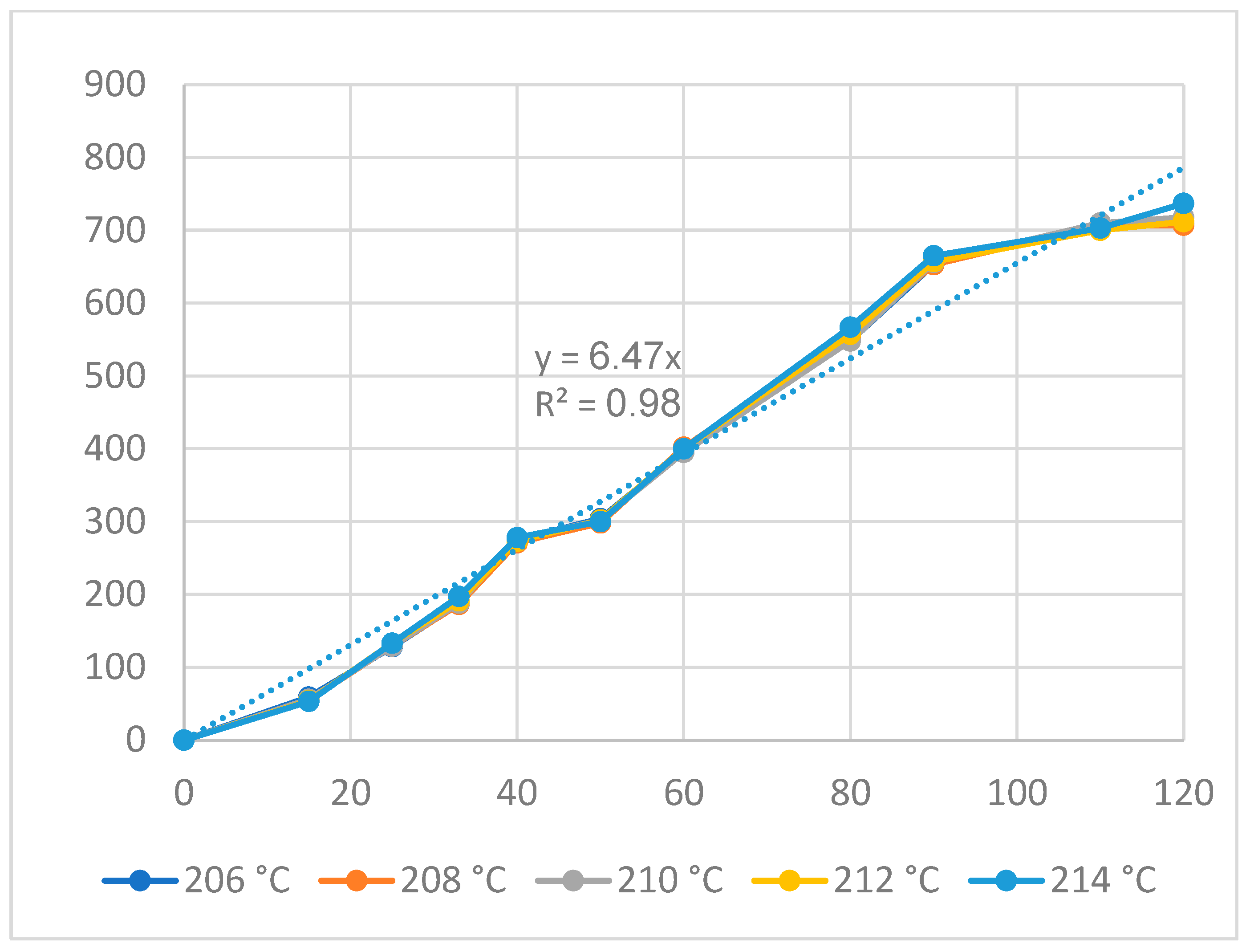
| 206 | |||||||
| 208 | |||||||
| 210 | |||||||
| 6 | 2.4 | 41 | 0.6 | 40 | 24 | 212 | 79 |
| 214 | |||||||
| 75 | |||||||
| 77 | |||||||
| 79 | |||||||
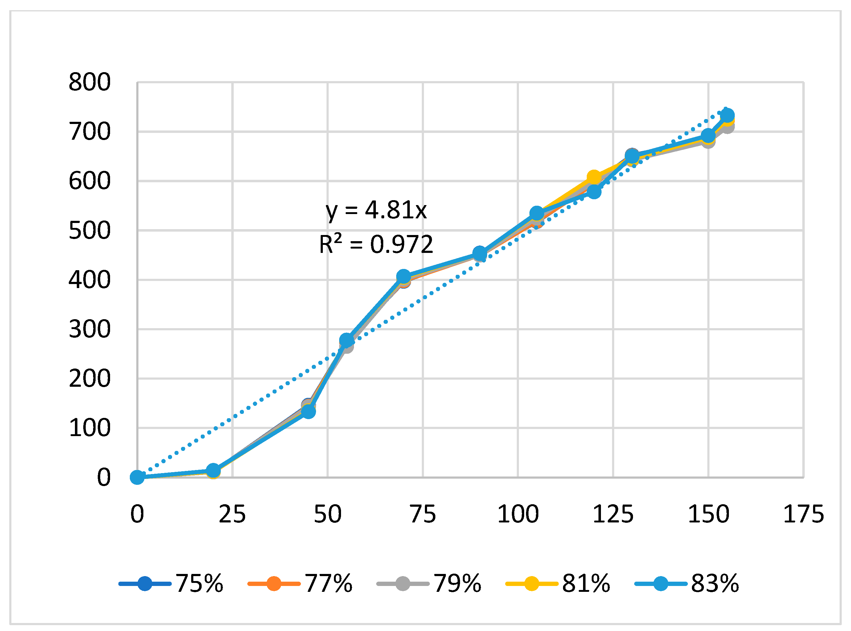
| 7 | 2.4 | 41 | 0.6 | 40 | 24 | 210 | 81 |
| 83 |
| Group | Filling Time (s) | Filling Pressure (bar) | Packing Time (s) | Packing Pressure (bar) | Cooling Time (s) | Melt Temperature (°C) | Filling Speed (%) |
|---|---|---|---|---|---|---|---|
| 1.5 | |||||||
| 1.7 | |||||||
| 1.9 | |||||||
| 1 | 2.1 | 27 | 0.6 | 25 | 54 | 214 | 54 |
| 2.3 | |||||||
| 25 | |||||||
| 26 | |||||||
| 27 | |||||||
| 2 | 1.9 | 28 | 0.6 | 25 | 54 | 214 | 54 |
| 29 | |||||||
| 0 | |||||||
| 0.3 | |||||||
| 0.6 | |||||||
| 3 | 1.9 | 41 | 0.9 | 25 | 54 | 214 | 54 |
| 1.2 | |||||||
| 23 | |||||||
| 24 | |||||||
| 25 | |||||||
| 4 | 1.9 | 41 | 0.6 | 26 | 54 | 214 | 54 |
| 27 | |||||||
| 50 | |||||||
| 52 | |||||||
| 54 | |||||||
| 5 | 1.9 | 41 | 0.6 | 25 | 56 | 214 | 54 |
| 58 | |||||||
| 210 | |||||||
| 212 | |||||||
| 214 | |||||||
| 6 | 1.9 | 41 | 0.6 | 25 | 54 | 216 | 54 |
| 218 | |||||||
| 50 | |||||||
| 52 | |||||||
| 54 | |||||||
| 7 | 1.9 | 41 | 0.6 | 25 | 54 | 214 | 56 |
| 58 |
| Injection Parameters | Equations |
|---|---|
| Filling time | y15 = 5.0x15; R2 = 0.938 |
| Filling pressure | y16 = 4.33x16; R2 = 0.967 |
| Filling speed | y17 = 4.23x17; R2 = 0.988 |
| Packing time | y18 = 5.4x18; R2 = 0.965 |
| Packing pressure | y19 = 2.89x19; R2 = 0.952 |
| Cooling time | y20 = 2.83x20; R2 = 0.942 |
| Melt temperature | y21 = 3.4x21; R2 = 0.993 |
| Materials | Amplification Ratio | References |
|---|---|---|
| ABS | 5.01–8.15 | This study |
| PP | 3.99–7.9 | This study |
| HDPE | 2.17–6.24 | This study |
| Aluminum alloys | 5–25 | Kim et al. [37] |
| Steel alloys | 16.2 | Na et al. [38] |
| Smart memory alloys | 2.2 | Maffiodo et al. [40] |
| Titanium alloys | 6.0 | Fiaz et al. [41] |
Disclaimer/Publisher’s Note: The statements, opinions and data contained in all publications are solely those of the individual author(s) and contributor(s) and not of MDPI and/or the editor(s). MDPI and/or the editor(s) disclaim responsibility for any injury to people or property resulting from any ideas, methods, instructions or products referred to in the content. |
© 2024 by the authors. Licensee MDPI, Basel, Switzerland. This article is an open access article distributed under the terms and conditions of the Creative Commons Attribution (CC BY) license (https://creativecommons.org/licenses/by/4.0/).
Share and Cite
Minh, P.S.; Nguyen, V.-T.; Uyen, T.M.T.; Huy, V.Q.; Le Dang, H.N.; Nguyen, V.T.T. Enhancing Amplification in Compliant Mechanisms: Optimization of Plastic Types and Injection Conditions. Polymers 2024, 16, 394. https://doi.org/10.3390/polym16030394
Minh PS, Nguyen V-T, Uyen TMT, Huy VQ, Le Dang HN, Nguyen VTT. Enhancing Amplification in Compliant Mechanisms: Optimization of Plastic Types and Injection Conditions. Polymers. 2024; 16(3):394. https://doi.org/10.3390/polym16030394
Chicago/Turabian StyleMinh, Pham Son, Van-Thuc Nguyen, Tran Minh The Uyen, Vu Quang Huy, Hai Nguyen Le Dang, and Van Thanh Tien Nguyen. 2024. "Enhancing Amplification in Compliant Mechanisms: Optimization of Plastic Types and Injection Conditions" Polymers 16, no. 3: 394. https://doi.org/10.3390/polym16030394