Article

Nanocrystalline Cellulose-Supported Iron Oxide Composite Materials for High-Performance Lithium-Ion Batteries

Department of Chemical and Biological Engineering, Gachon University, 1342 Seongnam-daero, Sujeong-gu, Seongnam-si 13120, Republic of Korea
*
Authors to whom correspondence should be addressed.
Polymers 2024, 16(5), 691; https://doi.org/10.3390/polym16050691
Submission received: 8 February 2024 / Revised: 27 February 2024 / Accepted: 28 February 2024 / Published: 2 March 2024
(This article belongs to the Special Issue Advanced Polymers for High-Performance Batteries)

Abstract

:
Nanocrystalline cellulose (NCC) can be converted into carbon materials for the fabrication of lithium-ion batteries (LIBs) as well as serve as a substrate for the incorporation of transition metal oxides (TMOs) to restrain the volume expansion, one of the most significant challenges of TMO-based LIBs. To improve the electrochemical performance and enhance the longer cycling stability of LIBs, a nanocrystalline cellulose-supported iron oxide (Fe2O3) composite (denoted as NCC–Fe2O3) is synthesized and utilized as electrodes in LIBs. The obtained NCC–Fe2O3 electrode exhibited stable cycling performance, better capacity, and high-rate capacity, and delivered a specific discharge capacity of 576.70 mAh g−1 at 100 mA g−1 after 1000 cycles. Moreover, the NCC–Fe2O3 electrode was restored and showed an upward trend of capacity after working at high current densities, indicating the fabricated composite is a promising approach to designing next-generation high-energy density lithium-ion batteries.

1. Introduction

Transition metal oxides (TMOs) (e.g., MnO2, ZnO, Fe2O3, Fe3O4, and SnO2) have become mainstream electrode materials in the field of lithium-ion batteries (LIBs) due to their high theoretical capacity [1,2,3,4]. Among them, iron oxide (Fe2O3) has been attractive and extensively considered as an ideal alternative electrode material because of its high theoretical capacity (1007 mAh g−1), low conversion voltage, and good stability as well as environmental friendliness [5,6]. Unfortunately, poor cycling stability due to poor electrical conductivity and structural collapse as a result of large volume expansion during the lithiation/delithiation process results in poor rate performance and a short life of LIBs.
One of the efficient approaches to overcome the disadvantages of Fe2O3 is a composite of nanosized Fe2O3 particles and conductive carbon-based materials such as graphene and carbon nanotubes (CNT) [7,8,9,10,11,12,13,14]. Incorporating nanosized Fe2O3 particles with carbon-based materials could couple the advantages of both nano entities, which improve the contact between electrode and electrolyte, and conductive carbonaceous materials, which alleviate the volume change and nanosized particle aggregation [3,15,16,17,18]. Furthermore, including a composite of iron oxide particles into carbonaceous materials could be easily carried out through thermal annealing of organic matter and inorganic compounds [3,9,19,20,21,22,23].
Nanocrystalline cellulose (NCC), one of the green carbon sources for electrode composite materials, exhibits a negative surface charge in solution [24,25]. The high surface energy of metal oxide nanoparticles leads to their self-aggregation, and the NCC owns its negative surface charge in solution. Thus, the complexation of NCC to metal oxides will help to decrease the high surface energy of nanosized metal oxide particles, which effectively prevents the aggregation of nanosized metal oxide particles [26,27,28]. In addition, the large surface and crystalline structure of nanocrystalline cellulose not only serve as the structural template in the carbonaceous metal oxides composite synthesis process but also effectively confine the Fe2O3 nanosized particles in a restricted area, reducing the volume expansion during the charge/discharge process, which improves both electrochemical performance and the stability of the electrode materials during the cycling of LIBs [27,28,29,30,31,32,33]. In addition, NCC contains numerous hydroxyl groups on its surface. Through various chemical modification processes, such as oxidation of the primary hydroxyl groups at the C6 position, carboxyl groups (-COOH) can be introduced onto the NCC surface (Figure S1) [34,35]. These carboxylic groups can interact with lithium ions and electrolyte components during battery operation and can facilitate the formation of a stable SEI layer by participating in the passivation reactions and stabilizing the solid–electrolyte interface. In addition, surface chemical modification and functionalized nanocrystalline cellulose using sodium periodate oxidation will transform at least part of the carboxylic groups of nanocrystalline cellulose into sodium carboxylate (-COO- +Na) groups. The sodium carboxylate groups in nanocrystalline cellulose materials could dissociate sodium ions into electrolytes, which can enhance the stable solid electrolyte interphase (SEI) layer formation and improve the stability of LIBs in long-term performance [35,36,37,38,39,40,41,42]. Furthermore, NCC’s electrochemical stability, mechanical strength, and natural sustainability also enhance the efficiency in composite synthesis and structural maintenance [26,27,43]. The low cost and light weight of NCC also help to extend its industrial and commercial applications, such as in anticorrosion coatings [44], single-molecule force spectroscopy (SMFS) measurements [45], electrochemical sensors [46], and in flexible energy and electronic devices [47].
In this work, we produced nanocrystalline cellulose-incorporated nanosized Fe2O3 particles to construct a composite as an electrode material for LIBs. The introduction of the NCC framework can effectively buffer the volume expansion and contraction during the discharge/charge process. The crystalline structure of NCC can promote lithium-ion transport and increase lithium storage [26,27,29,43]. The combination of nanosized Fe2O3 particles and NCC formed a high electrochemical performance composite, which delivers high specific capacity, outstandingly long cycle stability, and excellent rate performance when employed as an electrode material for LIBs.

2. Experiment Details

2.1. Materials

Spray-dried nanocrystalline cellulose powder derived from wood pulp, with dimensions of approximately 5 nanometers (nm) in diameter and 150–200 nanometers in length, purchased from Process Development Center, University of Maine, Orono, ME, USA (Lot #2015-FPL-CNC-071) is used as a cellulose source. Other chemicals, namely iron (II) chloride tetrahydrate (FeCl2·4H2O) and sodium citrate tribasic dihydrate (C6H5Na3O7·2H2O) were purchased from Sigma Aldrich Co., Ltd. (St. Louis, MO, USA) with all analytical grades and used without further purification.

2.2. Fabrication of Nanocrystalline Cellulose-Supported Iron Oxide Composite

The composite precursor was composited from mixtures of NCC, FeCl2·4H2O, and C6H5Na3O7·2H2O by using ethanol and deionized (DI) water (1:1) as a solvent. In the specific process, 50 nmol FeCl2·4H2O and 100 mmol C6H5Na3O7·2H2O were alternatively dispersed in 40 mL of an ethanol–water solution under vigorous stirring at room temperature for 1 h. A total of 1g of NCC was added into the solution and stirring continued at room temperature for 1 h to form a homogenous solution. The solution was then loaded into a 100 mL stainless steel autoclave. The solution was maintained for 8 h at 180 °C in an oven and then naturally cooled to room temperature. The precursor was collected via centrifugation, washed with DI water, and dried at 25 °C overnight. The obtained precursor was first stabilized for 4 h at 200 °C and then carbonized for 2 h at 500 °C in a nitrogen atmosphere with a heating rate of 5 °C min−1. The annealed sample that formed the nanocomposite structure with carbonized NCC and Fe2O3 was noted as NCC–Fe2O3. Then, NCC–Fe2O3 was designated as the electrode material for high-performance LIBs. A similar fabrication process was carried out under the same conditions without the existence of NCC and the final product was noted as Fe2O3 as a comparison electrode material.

2.3. Characterization

Powder X-ray diffraction (XRD) patterns were recorded on a diffractometer (Rigaku/Smartlab, Tokyo, Japan) at 40 kV, 30 mA X-ray generator with a Kβ filter for Cu radiation over the 2θ range of 10–100° at a scanning rate of 1.0° min−1. Thermogravimetric analysis (TGA) was performed under atmospheric conditions with a heating rate of 10 °C min−1. The morphologies and nanostructure of the samples were studied with a Hitachi S-4700 (Hitachi Ltd., Tokyo, Japan) field emission scanning electron microscope (SEM),with an accelerating voltage of 15kV, and a Tecnai F30S-Twin (Hillsboro, OR, USA) transmission electron microscope (TEM), with an accelerating voltage of 300 keV. The TEM observation samples were prepared by dropping sample-dispersed ethanol solution onto the copper grids. The elemental content and maps were obtained via energy-dispersive X-ray analysis (EDS). The size distribution of Fe2O3 was evaluated based on the SEM images. X-ray photoelectron spectroscopy (XPS) of the NCC–Fe2O3 composite was recorded on a PHI 5000 (ULVAC-PHI, Inc., Chigasaki, Kanagawa, Japan) to determine the element content of the composite, and Brunauer–Emmett–Teller (BET) specific surface areas of the NCC–Fe2O3 composite were determined via N2 adsorption at 77.3 K (Micromeritics, ASAP 2020, Norcross, GA, USA).

2.4. Electrochemical Performance Measurement

All the testing samples were prepared using a CR2023-type coin cell (Rotech Inc., Gwangju, Republic of Korea) in a glove box filled with pure argon to investigate the electrochemical performance of the NCC–Fe2O3 composite, and to compare the Fe2O3 sample. The electrode (mass load 0.88 mg/cm2) was composed of the obtained composites (70%), polyvinylidene fluoride (PVDF) binder (15%), and carbon black (15%), which were dissolved in an N-methyl pyrrolidone (NMP) solvent to form a smooth slurry. Then, the slurry was uniformly coated on a copper foil (r = 0.65 cm) and dried overnight at 70 °C in a vacuum oven for 24 h. Li foil was used as the anode, polyethylene membrane was applied as a separator, and 50 μL of 1 M LiPF6 in a mixed solvent of ethylene carbonate (EC)/dimethyl carbonate (DMC) with a volume ratio of 1:1 were used as an electrolyte for each electrode. Charge and discharge tests were conducted on a battery cycler (NanoCycler-01, NANOBASE, Geumcheon-gu, Seoul, Republic of Korea) over a potential range of 0.01~3.0 V vs. Li+/Li under a constant current density of 100 mA g−1 at room temperature. The rate performance tests were conducted on a range between 100 and 10,000 mA g−1 current densities. Cyclic voltammetry (CV) behaviors were studied by using a battery-cycle tester (WBCS3000, WonAtech, Seocho-gu, Seoul, Republic of Korea) with a voltage window of 0.01–3.0 V at a scan rate of 0.1 mV s−1. Electrochemical impedance spectroscopy (EIS) of the batteries was performed on the ZIVE MP1 (WonAtech, Seocho-gu, Seoul, Republic of Korea) analyzer, and the frequency was set from 100 kHz to 100 MHz with an AC amplitude of 10 mV.

3. Results and Discussion

To determine the phase composition and physical properties of the materials, the NCC–Fe2O3 composite and comparison Fe2O3 sample were first identified with X-ray diffraction, and the obtained results are shown in Figure 1a. As seen in Figure 1a, the diffraction peaks at 2θ = 24.33, 33.127, 35.607, 40.826, 49.443, 54.018, 57.54, 62.378, and 63.963° for the Fe2O3 sample are highly indexed to the characteristic patterns of Fe2O3 [ICCD No. 01-077-9925], which correspond to the (012), (104), (110), (113), (024), (116), (018), (214), and (300) planes of Fe2O3. There are no impurity peaks, and all the diffraction peaks are sharp, suggesting high purity and well-crystallized Fe2O3. Meanwhile, all diffraction peaks for the NCC–Fe2O3 composite are consistent with the characteristic peaks of Fe2O3. Moreover, the weakened and no-shifted peaks of the composite illustrated that Fe2O3 particles had been well introduced into the composite and connected on the surface of NCC. In addition, the appearance of diffraction peaks at 2θ = 31.148, 35.612, 42.69, and 56.39° for NCC–Fe2O3, assigned to the amorphous state of carbonaceous materials [ICCD Card No. 01-046-0943], show a slight shift of the obtained peaks centered at 34 and 40.2°; the presence of sharp peaks designates the crystalline nature of NCC, while the comparison Fe2O3 sample does not display this diffraction peaks, indicating the presence of NCC in the NCC–Fe2O3 composite and that the NCC–Fe2O3 composite was successfully constructed. The characteristic peaks of Fe2O3 and sharp carbonaceous structure diffraction peaks can be found clearly in the composite XRD patterns not only indicating that Fe2O3 had been well embedded into the NCC network but also suggesting the presence of a nanocrystalline structure of NCC after thermal reaction, which will help to prevent the aggregation of nanosized Fe2O3 particles and enhance the electrochemical performance.
To analyze the content of NCC in the NCC–Fe2O3 composite, a thermal gravimetric analysis (TGA) was conducted from room temperature to 800 °C at a heating rate of 5 m−1, and the obtained results for the NCC–Fe2O3 composite, NCC, and Fe2O3 samples are shown in Figure 1b. According to the TGA curves, the NCC–Fe2O3 composite indicates a significant mass loss between 250 °C and 400 °C and maintains a constant weight above 400 °C, and the extant material weight is 26.01%. This is most likely attributed to the combustion of NCC in the NCC–Fe2O3 composite. In addition, the TGA curve of NCC shows a light mass loss of approximately 7–8% below 250 °C, corresponding to impurities and adsorbed water present in the air, which is consistent with the obtained result for NCC–Fe2O3, and the major weight loss displayed between 250 and 500 °C is considered to be related to the carbonization of NCC [48]. These results show that the carbonization of NCC can proceed at temperatures ranging from 250 to 500 °C and can be conducted simultaneously through thermal annealing of Fe2O3 nanoparticles into the carbonaceous structure during the composite synthesis. On the other hand, the Fe2O3 sample shows that there is not much change, with a weight loss of 8.18%, corresponding to adsorbed water, trace amounts of oxygen, and easily oxidizable matter in the sample. Based on the change in TGA curves, the content of NCC in the NCC–Fe2O3 composite can be calculated to be 65.81%.
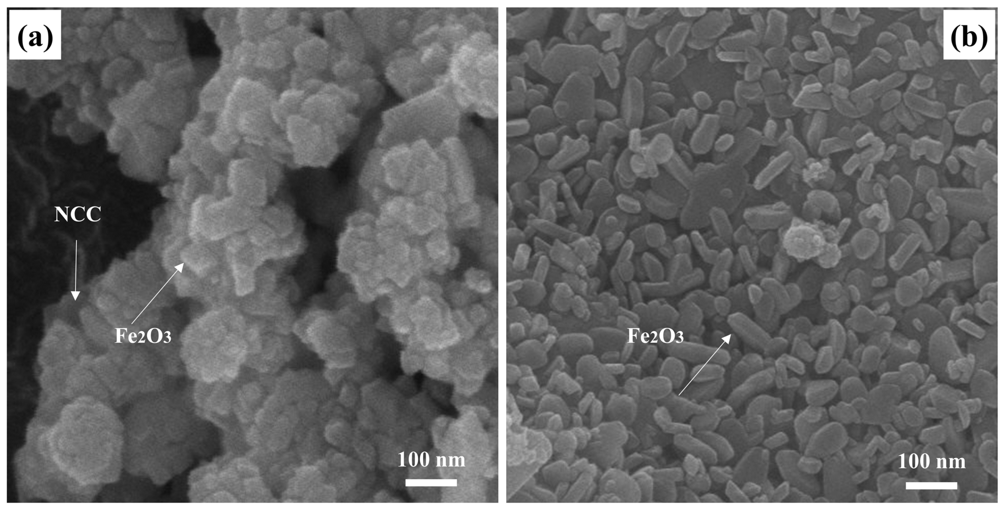
Figure 2 shows the typical morphologies of the NCC–Fe2O3 composite and a comparison Fe2O3 sample with the same magnification. It can be discerned that the NCC–Fe2O3 composite SEM image (Figure 2a) clearly shows that nanosized Fe2O3 particles are anchored on the NCC and exhibit an enlarged surface area, which is thus beneficial for enhancing the interface between materials and increasing the electrochemical properties. It is noted that the nanosized Fe2O3 particles almost retain the morphological properties in comparison to the typical morphological properties of the Fe2O3 sample, which can be obtained from Figure 2b. Furthermore, the majority of the nanosized Fe2O3 particles are exposed to the outside of the NCC, and a thin layer of NCC was coated on the surface of Fe2O3 that not only prevents the aggregation of Fe2O3, decreasing the volume expansion during the performance of composite, but also make sure that the Fe2O3 particles effectively connect with the lithium ions while avoiding direct contact with the electrolyte, exposing large electrochemical interaction sites and providing more active areas. In addition, three elements (Fe, C, and O) are explored in the composite, and the percentage of the three elements via EDS mapping are shown in Table 1. The percentage of Fe, C, and O are 14.98, 60.26, and 24.77%, respectively, which confirms the efficient assembly between Fe2O3 and NCC.
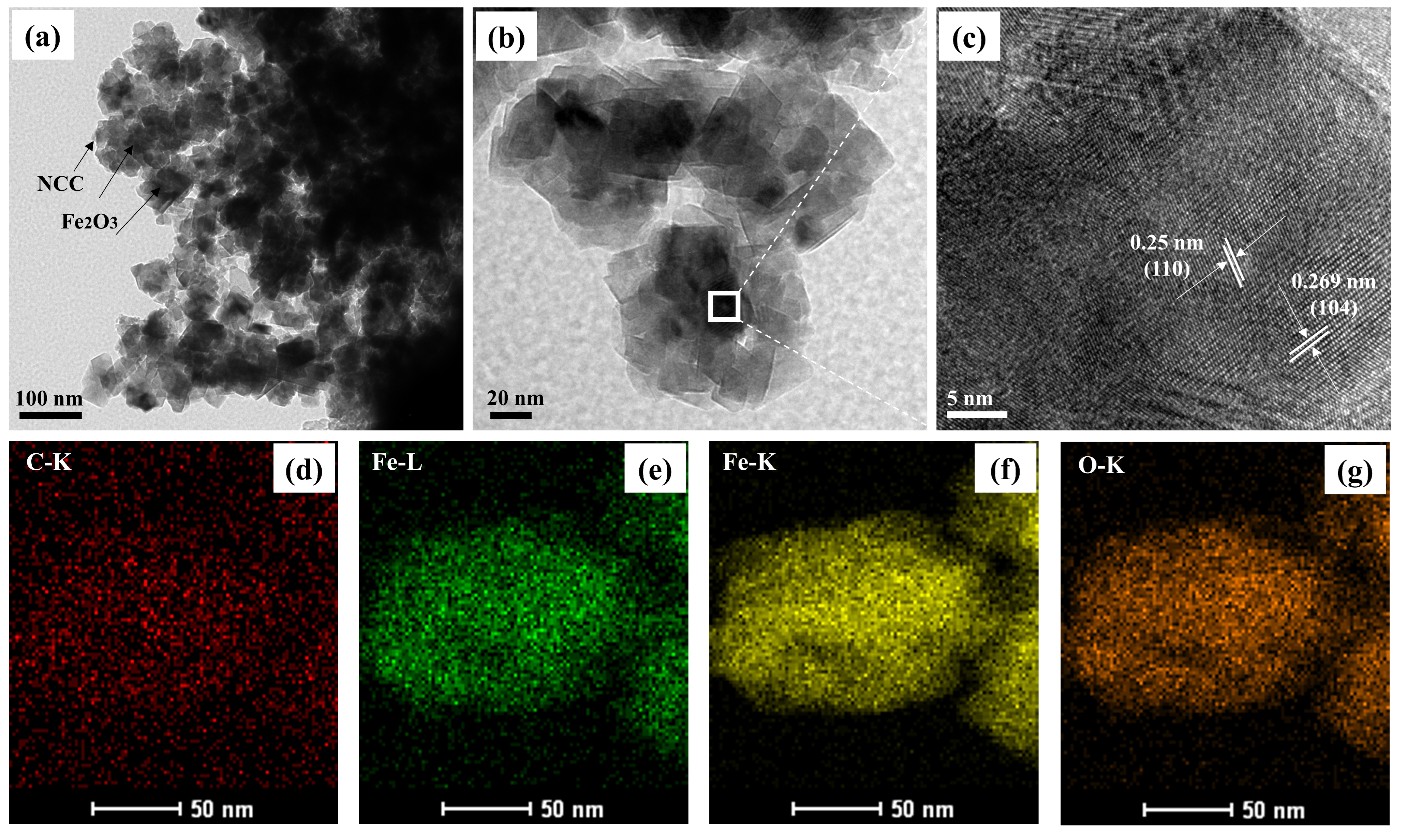
At the same time, the further detailed morphology of the NCC–Fe2O3 composite was observed via TEM and high-resolution TEM (HRTEM), and the obtained images are shown in Figure 3. TEM images (Figure 3a,b) present the uniformity of the anchored Fe2O3 particles on the NCC network, and a thin layer of NCC can be noted on the TEM images. Although some nanoparticle aggregation is observed in Figure 3a, the amorphous and large surface can be seen from the TEM images with higher magnification (Figure 3b), indicating the hierarchical porous structure and homogeneous dispersion of Fe2O3, which contribute to electron transportation and alleviate volume change to enhance the structural stability during the cycle. The HRTEM of the NCC–Fe2O3 composite (Figure 3c) shows the internal high-resolution lattice fringes, which confirm the existence of crystalline Fe2O3 particles with the lattice parameter of 0.25 and 0.269 nm corresponding to the (110) and (104) crystal plane of Fe2O3, showing consistency with the XRD results. In addition, the corresponding elemental mapping images (Figure 3d–g) for the elements of C, Fe, and O annotate a homogeneous distribution of Fe2O3 onto the NCC, which verifies the successful synthesis of the NCC–Fe2O3 composite as per the prediction made in advance.
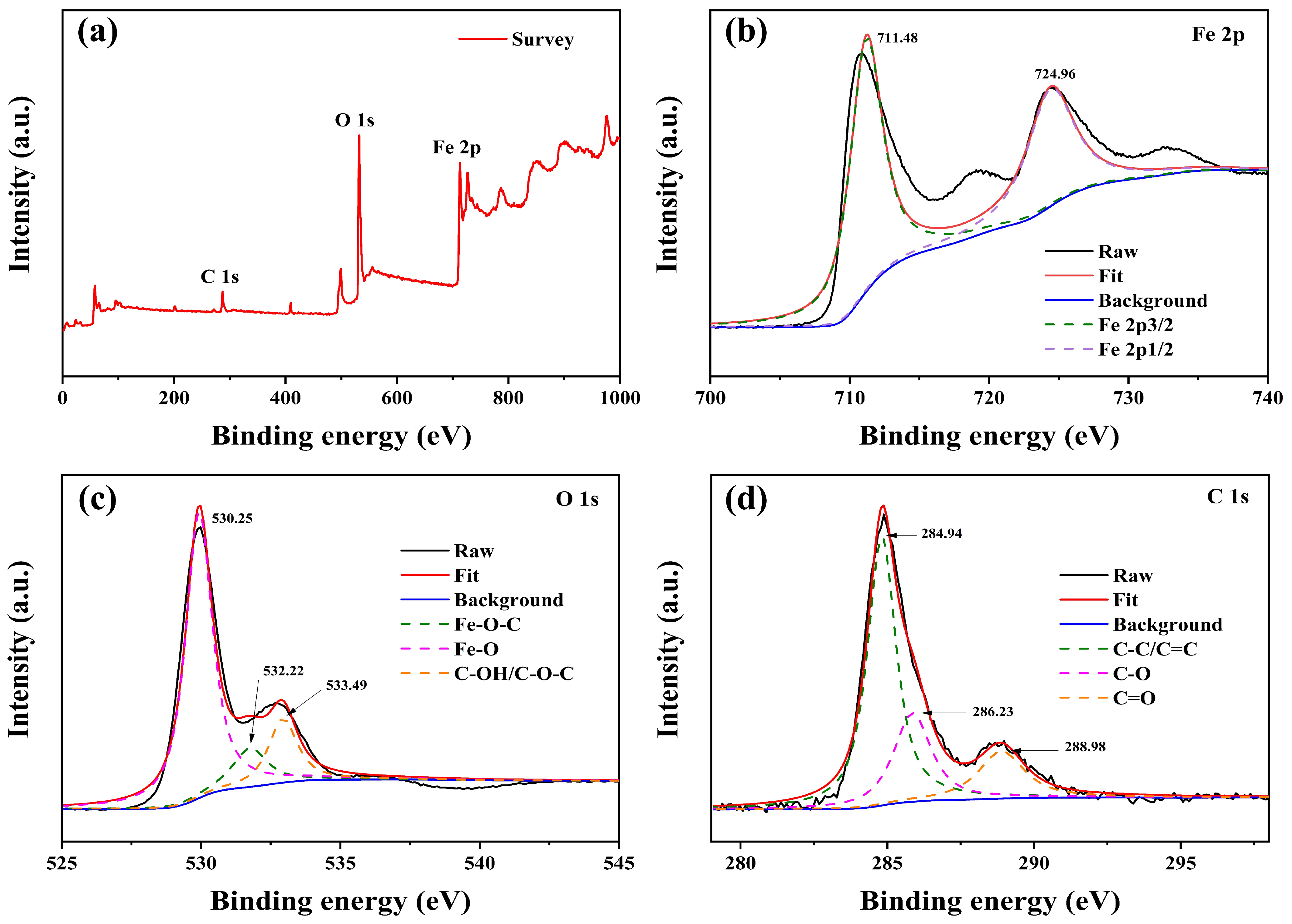
To further characterize the surface chemical composition of the NCC–Fe2O3 composite, X-ray photoelectron spectroscopy (XPS) was performed and the chemical element content and valence states are shown in Figure 4. According to Figure 4a, the full-range XPS survey spectrum consists of C 1s, O 1s, and Fe 2p with the peaks located at 287.05, 532.17, and 713.04 eV, respectively, which reveal that the NCC–Fe2O3 composite mainly contained three elements of Fe, C, and O.
In Figure 4b, the Fe 2p spectrum shows the two highest peaks at 711.48 and 724.96 eV, corresponding to Fe 2p3/2 and Fe 2p1/2, respectively, which further verify the presence of the Fe2O3 phase. A broad peak at 719.16 eV between Fe 2p3/2 and Fe 2p1/2 can be ascribed to the satellite peak of Fe3+ in Fe2O3, which is consistent with previous reports [11,20,49]. Figure 4c shows the detailed XPS spectrum of O 1s, which exhibits three peaks located at 530.25, 532.22, and 533.49 eV, demonstrating the Fe-O-C, Fe-O, and C-OH/C-O-C bonds to confirm the connection of Fe2O3 with NCC [10,20]. The peak positions of three parts divided in the C 1s XPS spectrum (Figure 4d) are 284.94, 286.23, and 288.98, corresponding to C-C/C=C, C-O, and C=O bonds, respectively, regarding the C atoms around the NCC [29]. The obtained XPS spectrums indicate that the NCC–Fe2O3 composite had been successfully fabricated.
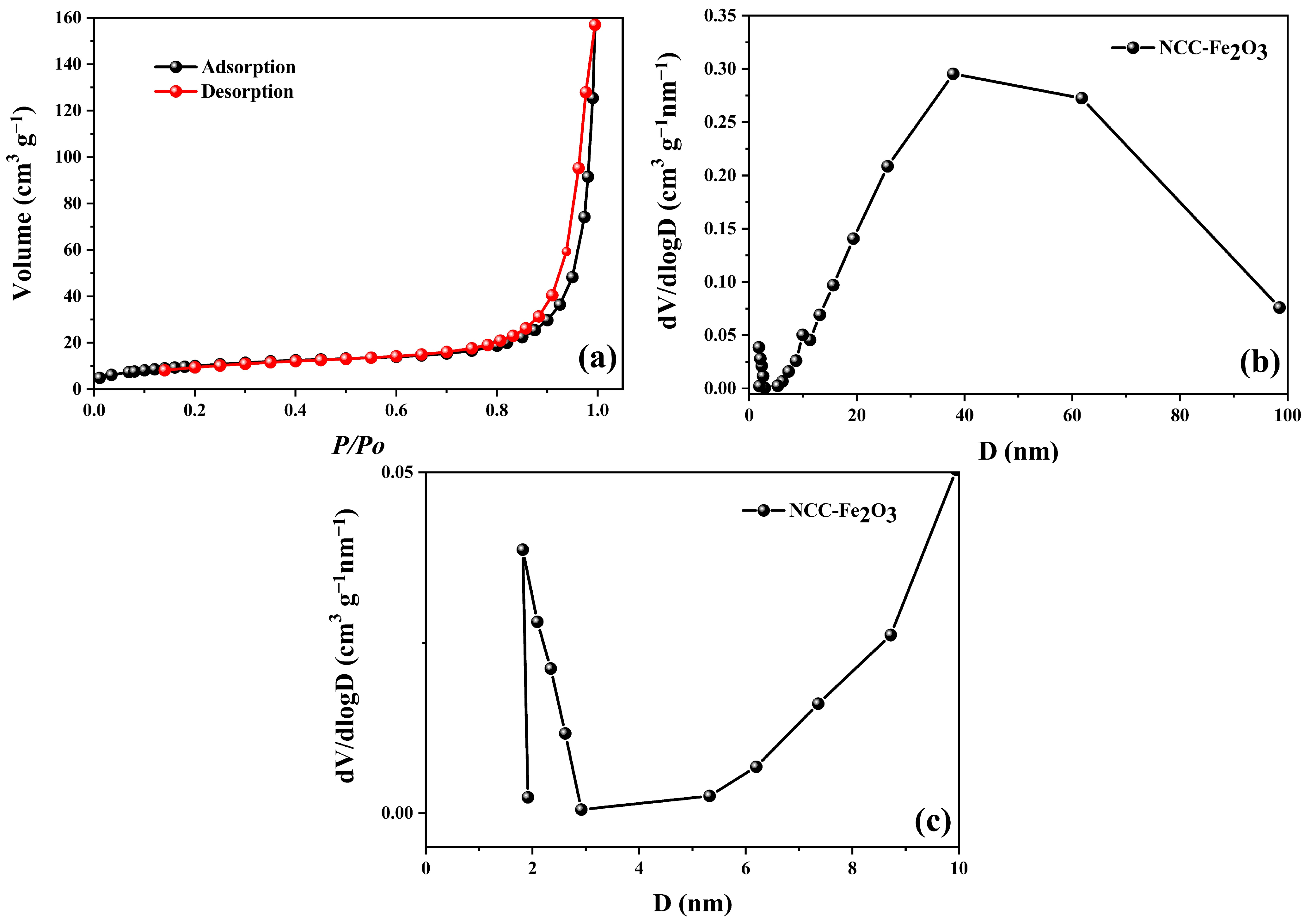
The nitrogen isothermal adsorption and desorption of the NCC–Fe2O3 composite were measured to evaluate the surface areas and porous nature of the composite and the results are displayed in Figure 5. As shown in Figure 5a, the composite shows a typical IV characteristic isotherm, indicating the presence of abundant mesopores. The pore size distribution of the NCC–Fe2O3 composite is shown in Figure 5b and ranges from 2 to 98 nm with a maximum peak pore diameter centered at 40 nm, representing the mesopores and macropores included in the composite. In addition, Figure 5c also points out that nanopores with an average size of 4 nm also exist in the composite. Furthermore, the Brunauer–Emmett–Teller (BET) specific surface areas (SSA) and pore volume (PV) of the NCC–Fe2O3 composite are 53.79 m2 g−1 and 0.244 cm3 g−1, respectively. The large BET surface area and meso–macroporous features could establish enough open channels, which not only facilitate the transportation of ions but also shorten the Li+ diffusion pathways, leading to the better utilization of active materials and storage of lithium ions during the cycling process and improving the electrochemical performance of the composite [9,50,51]. Furthermore, nanopores appearing in the composite can act as buffering spaces to manage the volume change of Fe2O3 instead of being destroyed in the lithiation/delithiation process, which can preclude the volume expansion of Fe2O3 in the composite to enhance the cycling stability of LIBs.
According to the analysis results, the NCC–Fe2O3 composite, which exhibits excellent physical properties, and the comparison Fe2O3 sample were applied as electrode materials in LIBs to investigate their electrochemical performance. The cycling performance of NCC–Fe2O3 and Fe2O3 electrodes was carried out at 100 mA g−1 current density for 1000 cycles to compare the electrochemical properties of the obtained composite and comparison material. The long-term cycle charge/discharge capacities and coulombic efficiency of both electrode materials for LIBs are shown in Figure 6a. The NCC–Fe2O3 composite delivers initial discharge/charge capacities of 1044.35/720.61 mAh g−1 with a coulombic efficiency (CE) of 69%. However, the dramatic capacity decay of NCC–Fe2O3 can be seen in the first 5 cycles and the capacity slowly decreases in the following 100 cycles, exhibiting a capacity loss of 59%. The decrease in reversible capacity from 1044.35 to 433.12 mAh g−1 after 100 cycles was mainly attributed to the volume expansion and reconstruction of Fe2O3 [7,9,12,30]. After this stage, the capacity value shows a steady increase and can maintain and remain at approximately 576.70 mAh g−1 after the last 1000th cycle, remaining at 55% first capacity, which confirms the excellent cycling performance of the NCC–Fe2O3 composite electrode. In addition, the CE rises to more than 95% in the following few cycles and quickly stabilizes at ~100% in the subsequent 1000 cycles. The continuously increasing trend of charge/discharge capacity for the cycle performance test of Fe2O3-NCC LIBs would be explained with three aspects, including the activated process of Fe2O3 particles, meaning that some blocked sites could be gradually activated with the increase in testing cycles, the “pseudo-capacitance-type behaviors” which reduce down Fe2O3 particles size, and the extra lithium-ion storage based on higher electrochemical surface which can maintain a stable SEI layer [52,53]. On the other hand, the incorporated tolerant and flexible NCC can help the relatively smaller size Fe2O3 particles be more well dispersed and anchored on NCC frameworks to effectively increase the usage of active materials, resulting in an increase and higher capacity during the cyclability process. Furthermore, the carbonaceous support from NCC can not only accommodate a volume change during the charge/discharge process but also can compensate for the low conductivity of Fe2O3 particles.
Nevertheless, the specific charge/discharge capacities of the comparison Fe2O3 sample are only 852.35/259.84 mAh g−1 in the first cycle, drop dramatically to 189.52/183.61 mAh g−1 in between the 1st and 10th cycles, maintain an unchanged state during the cycling performance test, and remain at 171.35 mAh g−1 (20% of initial capacity) after 1000 cycles. The NCC–Fe2O3 composite not only delivers higher specific capacities than the Fe2O3 sample but also demonstrates excellent cycling stability with better capacity retention.
The rate capability of the obtained NCC–Fe2O3 composite and comparison Fe2O3 sample at the different current density ranges of 0.1, 0.2, 0.5, 1, 2, 5, and 10 A g−1 are displayed in Figure 6b. The NCC–Fe2O3 composite exhibits average discharge capacities of 777.78, 577.36, 511.84, 466.77, 435.38, 431.29, and 431.53 mAh g−1 for five cycles at 0.1, 0.2, 0.5, 1, 2, 5, and 10 A g−1, respectively, much higher than those of the comparison Fe2O3 sample, which only delivers average capacities of 298.58, 110.27, 96.29, 86.08, 79.56, 78.7, and 78.39 mAh g−1 for five cycles with the same conditions. Moreover, the NCC–Fe2O3 composite discharge capacity can recover to a high value of 556.07 mAh g−1 when the current density returns to 0.1 A g−1 and shows an upward trend of specific capacity for the next 15 cycles, confirming both the excellent rate performance as well as structural stability of the NCC–Fe2O3 composite. The favorable rate performance of the NCC–Fe2O3 composite can be allocated to the composite’s porous structure and the effective influence and supporting role of NCC [20]. The integration of nanosized Fe2O3 particles into the NCC with the porous large surface structure effectively enhances the lithium storage performance of the NCC–Fe2O3 composite, which emphasizes the synergistic effect of carbonaceous material and nanosized Fe2O3 particles. Furthermore, the flexible NCC not only provides a highly conductive network to shorten and ensure the dispersal of lithium ions but also serves as a supporting layer, which minimizes the volume expansion and prevents the aggregation of Fe2O3 particles upon cycling. Table 2 shows a summary of the improvement capabilities of the NCC–Fe2O3 composite and a comparison of the Fe2O3 sample electrodes. As can be observed, the NCC–Fe2O3 electrode shows better initial capacity and CE, as well as remaining capacity after 1000 cycles, which proves the better electrochemical performance of the NCC–Fe2O3 composite in comparison to the Fe2O3 sample.
The discharge/charge curves of the NCC–Fe2O3 composite and comparison Fe2O3 sample for the 1st, 5th, 10th, 100th, 500th, and 1000th cycles at a current density of 100 mA g−1 with a potential voltage from 0.01 to 2 V are displayed in Figure 7a,b. As for NCC–Fe2O3 (Figure 7b), the first discharge/charge ratio capacity of 1174.4/794.1 mAh g−1 leads to an initial CE for the first cycle of 67.6%. The low CE and capacity loss in the first cycle are a response to the formation of the solid electrolyte interphase (SEI) layer and the lack of activation of NCC/Fe2O3 [15,16,19]. The CE value steadily increased and reached approximately ~100% after five cycles, which can be the result of the interactions between the electrolyte and active materials. In addition, the discharge/charge specific capacities of NCC–Fe2O3 gradually decrease until the 100th cycle and exhibit an increasing trend and show a better capacity value within 500 and 1000 cycles, which indicates the good reversibility of NCC–Fe2O3 after the activation process. Following the formation of an SEI layer, the reduction of Fe2O3 can be proved by the plateau identified around 0.72 V at the initial cycle. However, the observed plateau disappeared gradually when the working cycle increased, and the similarly shaped curve of subsequent cycles almost overlapped between the 500th and 1000th cycle, indicating the enhancement of the NCC–Fe2O3 composite’s electrochemical stability and cyclability. In comparison, the Fe2O3 sample shows a large capacity loss in the first cycle with an initial CE for the first discharge/charge ratio capacity of 865.36/454.27 mAh g−1 of 52.49% and exhibits a significant decrease after the 1st cycle and remains at a discharge capacity of 171.25 mAh g−1, 19.79% of the initial discharge capacity, after 1000 cycles.
Figure 7c,d show the initial discharge–charge profiles of the NCC–Fe2O3 composite and the comparison with the Fe2O3 sample electrodes at various current rates. The first discharge capacities of the NCC–Fe2O3 composite were recorded around 1260.47, 1239.67, 1145.81, 932.91, 742.77, 577.78, and 595.95 mAh g−1, respectively, at 0.1, 0.2, 0.5, 1, 2, 5, and 10 A g−1. Meanwhile, the Fe2O3 sample delivers first discharge capacity values of 860.85, 119.44, 104.11, 84.63, 82.01, 74.94, and 74.95 mAh g−1, which are considerably lower than the NCC–Fe2O3 electrode, at the same current density. Those results indicate the better performance, even though working under high current densities, of the NCC–Fe2O3 composite as well as reconfirm the supporting role of NCC for achieving a good rate performance in the composite. In addition, the NCC–Fe2O3 discharge/charge curves did not show plateaus when low current densities were applied, while a clear plateau can be observed at around 0.72 V for the Fe2O3 sample at 100 mA g−1, which agrees with the results shown in Figure 6b. Moreover, a plateau below 0.25 V appears in both samples when the current densities are above 2 A g−1, indicating that the lithium storage process can be affected by electrochemical redox reactions at high current densities. In addition, the charge/discharge profiles of NCC–Fe2O3 show similar shape curves and higher, gradually decreased specific capacity at all current densities, which not only confirms that the NCC–Fe2O3 composite is more stable than the Fe2O3 sample in various current densities but also demonstrates the favorable maintenance of the electrode structural integrity and conversion reactions at diverse current densities.
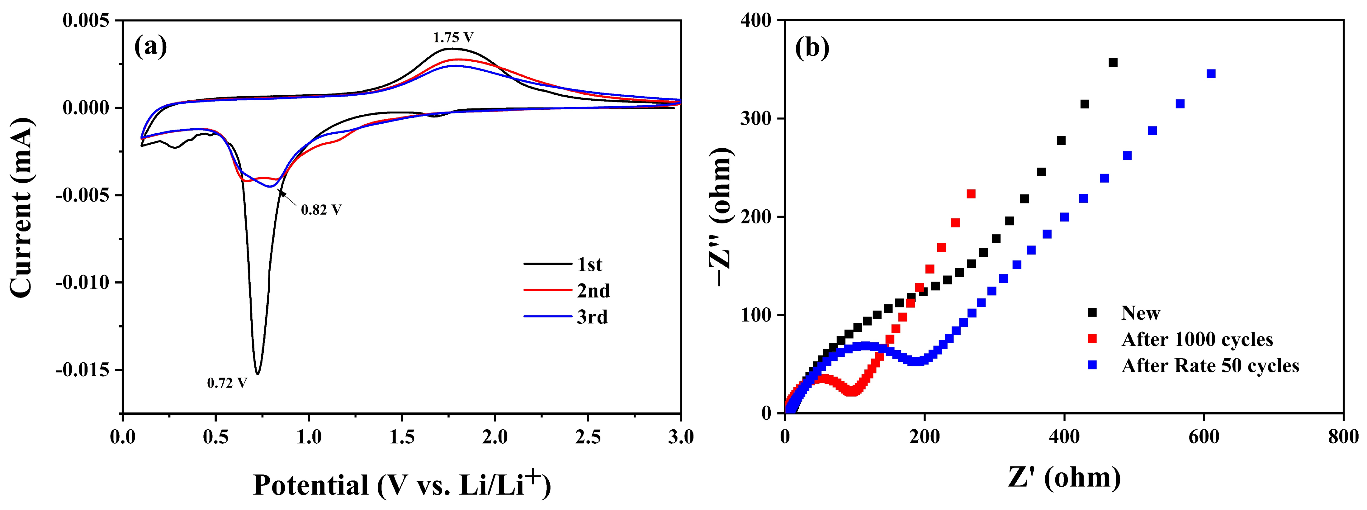
To further evaluate the detailed lithium storage process of the NCC–Fe2O3 composite when used as the electrode of LIBs, cyclic voltammetry (CV) was investigated, and the results are shown in Figure 8a. The CV curve for the initial cycle displays a dominant and sharp peak around 0.72 V, which is assigned to the reduction reaction of Fe2+ and Fe3+ to Fe0 and the formation of the SEI layer at the electrolyte/electrode interface, which is a common phenomenon in transition metal oxides electrodes. A minor peak around 1.7 V is presented for the transformation of Fe2O3 to the LixFe2O3 phase [20,30,54]. During the first anodic scan, a broad peak was observed at about 1.75 V, corresponding to the reversible oxidation of Fe0 to Fe2+ which is further oxidized to Fe3+ (Li2Fe2O3 + 4Li+ + 4e ⬄ 2Fe0 + 3Li2O) [20,30,55,56]. The appearance of the peak at 0.72 is consistent with the long plateau, which can be found in the galvanostatic charge and discharge profile of the NCC–Fe2O3 electrode. In the second cycle, the cathodic peaks exhibit different characteristic features in comparison with the first cycle, demonstrating the structural modification of materials. The minor peak at 1.7 V disappeared, and two broad peaks were observed between 0.68 and 0.85 V with a significant decrease in intensity, assigned to the presence of irreversible reactions and structural changes during the first cycle. Furthermore, the anodic peak shows a stable shape and little decay, indicating the good electrochemical reversibility of the electrode. Afterwards, the curve shows a slight shift toward a cathodic peak at 0.82 V and the broadening of its shape, decrease in its intensity, and high remaining trend of the anodic peak, demonstrating the high reversibility and capacity stability of the NCC–Fe2O3 composite during the delithiation process. The almost complete coincidence of the second and third cycle curves suggests the good cycling stability of the NCC–Fe2O3 composite, which again confirms the better cycling performance of LIBs (Figure 6a).
Electrochemical impedance spectroscopy (EIS) was also utilized to explain the electrochemical kinetics of the NCC–Fe2O3 composite electrode and the Nyquist diagram of the electrode before and after 1000 cycles and after 50 rate cycles, with the results shown in Figure 8b. As depicted in Figure 8b, the EIS curves of both electrodes after the rate and cycling process exhibit distinct semicircles in the high-frequency region and oblique straight lines in the low-frequency region, while the new electrode curve does not show a similar shape. The diameter of the semicircles in the high-frequency region is directly proportional to the charge transfer resistance (Rct) at the electrolyte–electrode interface. The semicircle diameters of the electrode after 1000 cycles and 50rate cycles are smaller than the new electrode, demonstrating the improvement of electrode electrochemical performance and explaining the increase in specific capacities during cycling (Figure 6). In addition, the specific Rct value of NCC–Fe2O3 after 1000 cycles (52.8 Ω) is smaller than after 50 rate cycle (103.29 Ω), indicating the better reaction kinetics at the electrode surface when the working cycles increase, and this result agrees with the electrochemical performance shown in Figure 6 and Figure 7.

4. Conclusions

In summary, we have successfully fabricated an NCC–Fe2O3 composite through a simple thermal annealing process. In the composite, NCC has been utilized as a flexible framework to incorporate Fe2O3 particles via in situ thermal decomposition, to play a supporting role in preventing the aggregation and volume expansion of Fe2O3. Furthermore, the abundant functional groups on the NCC surface allow it to coordinate with Fe2O3 particles, while the porous network and large surface enable the homogeneous dispersion of active materials. The prepared NCC–Fe2O3 composite is greatly improved with respect to electrochemical performance and structural stability. When applied in LIBs, the synthesized electrode not only displayed an excellent initial capacity of 1044.35 mAh g−1 and remained at 576.70 mAh g−1 after 1000 cycles at 100 mA g−1 but also exhibited a stable cyclability and outstanding rate performance, especially under high current densities. Having a simple synthesis process and good performance, the NCC–Fe2O3 composite could be a promising electrode material for high-performance LIBs. Furthermore, the continuously increasing trend of charge/discharge capacity after 1000 cycles indicates a promising approach to expanding the research on maximum running time exerted by NCC–Fe2O3 electrodes. In addition, the good rate performance at high current densities at 5 and 10 A g−1 shows the high potential for these electrode materials in the high-current battery industries and electronic devices.

Supplementary Materials

The following supporting information can be downloaded at: https://www.mdpi.com/article/10.3390/polym16050691/s1, Figure S1: Carboxyl groups on the NCC surface obtained through oxidation of the primary hydroxyl groups at the C6 position.

Author Contributions

Conceptualization, Q.N.T.; methodology, T.H.L.; validation, C.H.P.; formal analysis, Q.N.T.; investigation, Q.N.T.; writing—original draft preparation, Q.N.T.; writing—review and editing, Q.N.T., C.H.P. and T.H.L.; supervision, C.H.P.; project administration, C.H.P.; funding acquisition, C.H.P. All authors have read and agreed to the published version of the manuscript.

Funding

This work was supported by the Technology Development Program of MSS (RS-2023-00281725) and the ICT Development R&D Program of MSIT (RS-2023-00251670).

Institutional Review Board Statement

Not applicable.

Data Availability Statement

No new data were created.

Acknowledgments

The authors acknowledge and thank Sang Joon Park and Il Tae Kim for their support during the experiments, materials characterization equitment and battery testing measurement.

Conflicts of Interest

The authors declare no conflict of interest.

References

  1. Zhu, J.; Ding, Y.; Ma, Z.; Tang, W.; Chen, X.; Lu, Y. Recent Progress on Nanostructured Transition Metal Oxides As Anode Materials for Lithium-Ion Batteries. J. Electron. Mater. 2022, 51, 3391–3417. [Google Scholar] [CrossRef]
  2. Cao, Y.; He, Y.; Gang, H.; Wu, B.; Yan, L.; Wei, D.; Wang, H. Stability Study of Transition Metal Oxide Electrode Materials. J. Power Sources 2023, 560, 232710. [Google Scholar] [CrossRef]
  3. Nandagudi, A.; Nagarajarao, S.H.; Santosh, M.S.; Basavaraja, B.M.; Malode, S.J.; Mascarenhas, R.J.; Shetti, N.P. Hydrothermal Synthesis of Transition Metal Oxides, Transition Metal Oxide/Carbonaceous Material Nanocomposites for Supercapacitor Applications. Mater. Today Sustain. 2022, 19, 100214. [Google Scholar] [CrossRef]
  4. Kim, S.H.; Park, C.H.; Lee, H. Recent Research Trend in Conductive Polymer Binders for Silicon-Based Anodes of Lithium-Ion Batteries. J. Adhes. Interface 2023, 24, 9–16. [Google Scholar]
  5. Zhang, L.; Wu, H.B.; Lou, X.W. Iron-Oxide-Based Advanced Anode Materials for Lithium-Ion Batteries. Adv. Energy Mater. 2014, 4, 1300958. [Google Scholar] [CrossRef]
  6. Jiang, J.; Liu, J. Iron Anode-based Aqueous Electrochemical Energy Storage Devices: Recent Advances and Future Perspectives. Interdiscip. Mater. 2022, 1, 116–139. [Google Scholar] [CrossRef]
  7. Zhang, G.; Shi, Y.; Wang, H.; Jiang, L.; Yu, X.; Jing, S.; Xing, S.; Tsiakaras, P. A Facile Route to Achieve Ultrafine Fe2O3 Nanorods Anchored on Graphene Oxide for Application in Lithium-Ion Battery. J. Power Sources 2019, 416, 118–124. [Google Scholar] [CrossRef]
  8. Li, J.; Ma, Z.; Hao, S.; Di, S.; Su, L.; Qin, X.; Shao, G. In Situ Fabrication of Hierarchical Iron Oxide Spheres@N-Doped 3D Porous Graphene Aerogel for Superior Lithium Storage. Ionics 2020, 26, 2303–2314. [Google Scholar] [CrossRef]
  9. Han, T.; Wei, Y.; Jin, X.; Jiu, H.; Zhang, L.; Sun, Y.; Tian, J.; Shang, R.; Hang, D.; Zhao, R. Hydrothermal Self-Assembly of α-Fe2O3 Nanorings@graphene Aerogel Composites for Enhanced Li Storage Performance. J. Mater. Sci. 2019, 54, 7119–7130. [Google Scholar] [CrossRef]
  10. Li, L.; Zhou, G.; Weng, Z.; Shan, X.Y.; Li, F.; Cheng, H.M. Monolithic Fe2O3/Graphene Hybrid for Highly Efficient Lithium Storage and Arsenic Removal. Carbon 2014, 67, 500–507. [Google Scholar] [CrossRef]
  11. Qi, X.; Zhang, H.B.; Xu, J.; Wu, X.; Yang, D.; Qu, J.; Yu, Z.Z. Highly Efficient High-Pressure Homogenization Approach for Scalable Production of High-Quality Graphene Sheets and Sandwich-Structured α-Fe2O3/Graphene Hybrids for High-Performance Lithium-Ion Batteries. ACS Appl. Mater. Interfaces 2017, 9, 11025–11034. [Google Scholar] [CrossRef] [PubMed]
  12. Cao, Y.; Zhang, A.Q.; Zhang, H.; Ding, G.Q.; Zhang, L. Sen A Facile Route to Achieve Fe2O3 Hollow Sphere Anchored on Carbon Nanotube for Application in Lithium-Ion Battery. Inorg. Chem. Commun. 2020, 111, 107633. [Google Scholar] [CrossRef]
  13. Sheng, S.; Gao, H.; Liu, X.; Wang, Z.; Zhao, Y. Rational Fabrication and Improved Lithium Ion Battery Performances of Carbon Nanofibers Incorporated with α-Fe2O3 Hollow Nanoballs. Surfaces and Interfaces 2020, 21, 100612. [Google Scholar] [CrossRef]
  14. Cui, X.; Zhu, Y.; Li, F.; Liu, D.; Chen, J.; Zhang, Y.; Zhang, L.L.; Ji, J. Enhanced Rate Capability of a Lithium Ion Battery Anode Based on Liquid-Solid-Solution Assembly of Fe2O3 on Crumpled Graphene. RSC Adv. 2016, 6, 9007–9012. [Google Scholar] [CrossRef]
  15. Liu, H.; Luo, S.H.; Yan, S.X.; Wang, Q.; Hu, D.B.; Wang, Y.L.; Feng, J.; Yi, T.F. High-Performance α-Fe 2 O 3 /C Composite Anodes for Lithium-Ion Batteries Synthesized by Hydrothermal Carbonization Glucose Method Used Pickled Iron Oxide Red as Raw Material. Compos. B Eng. 2019, 164, 576–582. [Google Scholar] [CrossRef]
  16. Zhang, Z.; Liang, J.; Zhang, X.; Yang, W.; Dong, X.; Jung, Y. Dominant Pseudocapacitive Lithium Storage in the Carbon-Coated Ferric Oxide Nanoparticles (Fe2O3@C) towards Anode Materials for Lithium-Ion Batteries. Int. J. Hydrogen Energy 2020, 45, 8186–8197. [Google Scholar] [CrossRef]
  17. Wang, J.; Ma, C.; Tang, J.; Yang, X.; Wang, Y.; Jia, X.; Cai, W.; Qiao, W.; Ling, L. Facile Fabrication of Fe2O3-Decorated Carbon Matrixes with a Multidimensional Structure as Anodes for Lithium-Ion Batteries. Energy Fuels 2021, 35, 816–826. [Google Scholar] [CrossRef]
  18. Liu, H.; Luo, S.H.; Hu, D.B.; Liu, X.; Wang, Q.; Wang, Z.Y.; Wang, Y.L.; Chang, L.J.; Liu, Y.G.; Yi, T.F.; et al. Design and Synthesis of Carbon-Coated α-Fe2O3@Fe3O4 Heterostructured as Anode Materials for Lithium Ion Batteries. Appl. Surf. Sci. 2019, 495, 143590. [Google Scholar] [CrossRef]
  19. Wang, X.; Wang, J.; Chen, Z.; Yang, K.; Zhang, Z.; Shi, Z.; Mei, T.; Qian, J.; Li, J.; Wang, X. Yolk-Double Shell Fe3O4@C@C Composite as High-Performance Anode Materials for Lithium-Ion Batteries. J. Alloys Compd. 2020, 822, 153656. [Google Scholar] [CrossRef]
  20. Liu, R.; Liu, H.; Yang, Q.; Ma, Y.; Dong, D.; Wang, J. Longan-Derived Biomass Carbon-Induced Cubic-Type Ferric Oxide Nanoparticles for Efficient Lithium-Ion Battery Anodes. Energy Fuels 2023, 37, 16979–16987. [Google Scholar] [CrossRef]
  21. Zhu, W.; Kierzek, K.; Wang, S.; Li, S.; Holze, R.; Chen, X. Improved Performance in Lithium Ion Battery of CNT-Fe3O4@graphene Induced by Three-Dimensional Structured Construction. Colloids Surf. A Physicochem. Eng. Asp. 2021, 612, 126014. [Google Scholar] [CrossRef]
  22. Wang, R.; Xu, C.; Sun, J.; Gao, L.; Lin, C. Flexible Free-Standing Hollow Fe3O4/Graphene Hybrid Films for Lithium-Ion Batteries. J. Mater. Chem. A Mater. 2013, 1, 1794–1800. [Google Scholar] [CrossRef]
  23. Li, H.; Wang, J.; Li, Y.; Zhao, Y.; Tian, Y.; Kurmanbayeva, I.; Bakenov, Z. Hierarchical Sandwiched Fe3O4@C/Graphene Composite as Anode Material for Lithium-Ion Batteries. J. Electroanal. Chem. 2019, 847, 113240. [Google Scholar] [CrossRef]
  24. Zhong, L.; Fu, S.; Peng, X.; Zhan, H.; Sun, R. Colloidal Stability of Negatively Charged Cellulose Nanocrystalline in Aqueous Systems. Carbohydr. Polym. 2012, 90, 644–649. [Google Scholar] [CrossRef]
  25. Iqbal, M.A.; Akhter, T.; Faheem, M.; Mahmood, A.; Al-Masry, W.; Nadeem, S.; Hassan, S.U.; Park, C.H. Metal-Free, Visible Light-Mediated Atom Transfer Radical Polymerization of Hydroxypropyl Cellulose-Graft-Poly(Methyl Methacrylate)s: Effect of Polymer Side Chains on Thermo-Responsive Behavior of Hydroxypropyl Cellulose. Cellulose 2023, 30, 7519–7533. [Google Scholar] [CrossRef]
  26. Xu, T.; Du, H.; Liu, H.; Liu, W.; Zhang, X.; Si, C.; Liu, P.; Zhang, K. Advanced Nanocellulose-Based Composites for Flexible Functional Energy Storage Devices. Adv. Mater. 2021, 33, 2101368. [Google Scholar] [CrossRef] [PubMed]
  27. Chen, Z.; Hu, Y.; Shi, G.; Zhuo, H.; Ali, M.A.; Jamróz, E.; Zhang, H.; Zhong, L.; Peng, X. Advanced Flexible Materials from Nanocellulose. Adv. Funct. Mater. 2023, 33, 2214245. [Google Scholar] [CrossRef]
  28. Gou, J.; Liu, W.; Tang, A. A Renewable and Biodegradable Nanocellulose-Based Gel Polymer Electrolyte for Lithium-Ion Battery. J. Mater. Sci. 2020, 55, 10699–10711. [Google Scholar] [CrossRef]
  29. Wang, D.C.; Lei, S.N.; Zhong, S.; Xiao, X.; Guo, Q.H. Cellulose-Based Conductive Materials for Energy and Sensing Applications. Polymers 2023, 15, 4159. [Google Scholar] [CrossRef]
  30. Huang, Y.; Lin, Z.; Zheng, M.; Wang, T.; Yang, J.; Yuan, F.; Lu, X.; Liu, L.; Sun, D. Amorphous Fe2O3 Nanoshells Coated on Carbonized Bacterial Cellulose Nanofibers as a Flexible Anode for High-Performance Lithium Ion Batteries. J. Power Sources 2016, 307, 649–656. [Google Scholar] [CrossRef]
  31. Nguyen, H.K.; Bae, J.; Hur, J.; Park, S.J.; Park, M.S.; Kim, I.T. Tailoring of Aqueous-Based Carbon Nanotube-Nanocellulose Films as Self-Standing Flexible Anodes for Lithium-Ion Storage. Nanomaterials 2019, 9, 655. [Google Scholar] [CrossRef]
  32. Farooq, A.; Patoary, M.K.; Zhang, M.; Mussana, H.; Li, M.; Naeem, M.A.; Mushtaq, M.; Farooq, A.; Liu, L. Cellulose from Sources to Nanocellulose and an Overview of Synthesis and Properties of Nanocellulose/Zinc Oxide Nanocomposite Materials. Int. J. Biol. Macromol. 2020, 154, 1050–1073. [Google Scholar] [CrossRef]
  33. Ullah, M.W.; Manan, S.; Ul-Islam, M.; Vasilyevich, R.V.; Thomas, S.; Yang, G. Introduction to Nanocellulose. In Nanocellulose: Synthesis, Structure, Properties and Applications; World Scientific Publishers: Singapore, 2021. [Google Scholar]
  34. Postek, M.T.; Moon, R.J.; Rudie, A.W.; Bilodeau, M.A. Production and Applications of Cellulose Nanomaterials; Tappi Press: Atlanta, GA, USA, 2013; pp. 1–28. [Google Scholar]
  35. Lam, E.; Hemraz, U.D. Preparation and Surface Functionalization of Carboxylated Cellulose Nanocrystals. Nanomaterials 2021, 11, 1641. [Google Scholar] [CrossRef]
  36. Buqa, H.; Holzapfel, M.; Krumeich, F.; Veit, C.; Novák, P. Study of Styrene Butadiene Rubber and Sodium Methyl Cellulose as Binder for Negative Electrodes in Lithium-Ion Batteries. J. Power Sources 2006, 161, 617–622. [Google Scholar] [CrossRef]
  37. Wan, Y.; Yang, Z.; Xiong, G.; Luo, H. A General Strategy of Decorating 3D Carbon Nanofiber Aerogels Derived from Bacterial Cellulose with Nano-Fe3O4 for High-Performance Flexible and Binder-Free Lithium-Ion Battery Anodes. J. Mater. Chem. A Mater. 2015, 3, 15386–15393. [Google Scholar] [CrossRef]
  38. Han, W.; Xiao, Y.; Yin, J.; Gong, Y.; Tuo, X.; Cao, J. Fe3O4@carbon Nanofibers Synthesized from Cellulose Acetate and Application in Lithium-Ion Battery. Langmuir 2020, 36, 11237–11244. [Google Scholar] [CrossRef] [PubMed]
  39. Peng, S.; Luo, Q.; Zhou, G.; Xu, X. Recent Advances on Cellulose Nanocrystals and Their Derivatives. Polymers 2021, 13, 3247. [Google Scholar] [CrossRef] [PubMed]
  40. Zhang, T.; Lang, J.; Liu, L.; Liu, L.; Li, H.; Gu, Y.; Yan, X.; Ding, X. Effect of Carboxylic Acid Groups on the Supercapacitive Performance of Functional Carbon Frameworks Derived from Bacterial Cellulose. Chin. Chem. Lett. 2017, 28, 2212–2218. [Google Scholar] [CrossRef]
  41. Shen, F.; Zhu, H.; Luo, W.; Wan, J.; Zhou, L.; Dai, J.; Zhao, B.; Han, X.; Fu, K.; Hu, L. Chemically Crushed Wood Cellulose Fiber towards High-Performance Sodium-Ion Batteries. ACS Appl. Mater. Interfaces 2015, 7, 23291–23296. [Google Scholar] [CrossRef]
  42. Lu, H.; Behm, M.; Leijonmarck, S.; Lindbergh, G.; Cornell, A. Flexible Paper Electrodes for Li-Ion Batteries Using Low Amount of TEMPO-Oxidized Cellulose Nanofibrils as Binder. ACS Appl. Mater. Interfaces 2016, 8, 18097–18106. [Google Scholar] [CrossRef] [PubMed]
  43. Kim, H.; Mattinen, U.; Guccini, V.; Liu, H.; Salazar-Alvarez, G.; Lindström, R.W.; Lindbergh, G.; Cornell, A. Feasibility of Chemically Modified Cellulose Nanofiber Membranes as Lithium-Ion Battery Separators. ACS Appl. Mater. Interfaces 2020, 12, 41211–41222. [Google Scholar] [CrossRef]
  44. Wang, Z.; Hu, B.; Yu, H.; Chen, G.Z. Synergistic Effects of 1-Octyl-3-Methylimidazolium Hexafluorophosphate and Cellulose Nanocrystals on Improving Polyacrylate Waterborne Anti-Corrosion Coatings. Polymers 2023, 15, 810. [Google Scholar] [CrossRef]
  45. Marcuello, C.; Foulon, L.; Chabbert, B.; Molinari, M.; Aguié-Béghin, V. Langmuir-Blodgett Procedure to Precisely Control the Coverage of Functionalized AFM Cantilevers for SMFS Measurements: Application with Cellulose Nanocrystals. Langmuir 2018, 34, 9376–9386. [Google Scholar] [CrossRef]
  46. Fan, J.; Xu, M.; Xu, Y.T.; Hamad, W.Y.; Meng, Z.; MacLachlan, M.J. A Visible Multi-Response Electrochemical Sensor Based on Cellulose Nanocrystals. Chem. Eng. J. 2023, 457, 141175. [Google Scholar] [CrossRef]
  47. Dias, O.A.T.; Konar, S.; Leão, A.L.; Yang, W.; Tjong, J.; Sain, M. Current State of Applications of Nanocellulose in Flexible Energy and Electronic Devices. Front. Chem. 2020, 8, 420. [Google Scholar] [CrossRef]
  48. Rhim, Y.R.; Zhang, D.; Fairbrother, D.H.; Wepasnick, K.A.; Livi, K.J.; Bodnar, R.J.; Nagle, D.C. Changes in Electrical and Microstructural Properties of Microcrystalline Cellulose as Function of Carbonization Temperature. Carbon 2010, 48, 1012–1024. [Google Scholar] [CrossRef]
  49. Vo, T.N.; Nguyen, T.A.; Nguyen, D.M.K.; Nguyen, M.T.; Nguyen, T.L.T.; Le, M.L.P.; Nguyen, V.H.; Tran, V.M.; Nguyen, D.Q.; Kim, I.T.; et al. Synthesis of ZnFe2O4 Spinel Nanoparticles at Varying PH Values and Application in Anode Material for Lithium-Ion Battery. Ceram. Int. 2023, 49, 38824–38834. [Google Scholar] [CrossRef]
  50. Jia, X.; Lian, D.; Shi, B.; Dai, R.; Li, C.; Wu, X. Facile Synthesis of α-Fe2O3@graphene Oxide Nanocomposites for Enhanced Gas-Sensing Performance to Ethanol. J. Mater. Sci. Mater. Electron. 2017, 28, 12070–12079. [Google Scholar] [CrossRef]
  51. Wang, R.; Xu, C.; Du, M.; Sun, J.; Gao, L.; Zhang, P.; Yao, H.; Lin, C. Solvothermal-Induced Self-Assembly of Fe2O3/GS Aerogels for High Li-Storage and Excellent Stability. Small 2014, 10, 2260–2269. [Google Scholar] [CrossRef] [PubMed]
  52. Hu, Y.Y.; Liu, Z.; Nam, K.W.; Borkiewicz, O.J.; Cheng, J.; Hua, X.; Dunstan, M.T.; Yu, X.; Wiaderek, K.M.; Du, L.S.; et al. Origin of Additional Capacities in Metal Oxide Lithium-Ion Battery Electrodes. Nat. Mater. 2013, 12, 1130–1136. [Google Scholar] [CrossRef]
  53. Luo, J.; Liu, J.; Zeng, Z.; Ng, C.F.; Ma, L.; Zhang, H.; Lin, J.; Shen, Z.; Fan, H.J. Three-Dimensional Graphene Foam Supported Fe3O4 Lithium Battery Anodes with Long Cycle Life and High Rate Capability. Nano Lett. 2013, 13, 6136–6143. [Google Scholar] [CrossRef] [PubMed]
  54. Long, Z.; Yuan, L.; Shi, C.; Wu, C.; Qiao, H.; Wang, K. Porous Fe2O3 Nanorod-Decorated Hollow Carbon Nanofibers for High-Rate Lithium Storage. Adv. Compos. Hybrid. Mater. 2022, 5, 370–382. [Google Scholar] [CrossRef]
  55. Liu, L.; Yang, X.; Lv, C.; Zhu, A.; Zhu, X.; Guo, S.; Chen, C.; Yang, D. Seaweed-Derived Route to Fe2O3 Hollow Nanoparticles/N-Doped Graphene Aerogels with High Lithium Ion Storage Performance. ACS Appl. Mater. Interfaces 2016, 8, 7047–7053. [Google Scholar] [CrossRef] [PubMed]
  56. Wu, S.; Jin, Y.; Wang, D.; Xu, Z.; Li, L.; Zou, X.; Zhang, M.; Wang, Z.; Yang, H. Fe2O3/Carbon Derived from Peanut Shell Hybrid as an Advanced Anode for High Performance Lithium Ion Batteries. J. Energy Storage 2023, 68, 107731. [Google Scholar] [CrossRef]
Figure 1. Typical characterizations of the obtained composite NCC–Fe2O3 and Fe2O3 sample. (a) XRD patterns and (b) TGA curves.
Polymers 16 00691 g001
Figure 2. SEM images of (a) NCC–Fe2O3 composite and (b) Fe2O3 sample.
Polymers 16 00691 g002
Figure 3. (a) Typical TEM image, (b,c) HRTEM images and EDS full elemental mapping images, and (d) C, (e,f) Fe, and (g) O of NCC–Fe2O3 composite.
Polymers 16 00691 g003
Figure 4. (a) XPS survey spectrum of NCC–Fe2O3 composite and high-resolution XPS peaks of (b) Fe 2p, (c) O 1s, and (d) C1s.
Polymers 16 00691 g004
Figure 5. (a) Nitrogen adsorption–desorption isotherm, (b) BJH pore size distribution, and (c) nanopore distribution for the NCC–Fe2O3 composite.
Polymers 16 00691 g005
Figure 6. (a) Long-term cycling performance and coulombic efficiency at 100 mA g−1 and (b) rate capability performance of NCC–Fe2O3 composite and Fe2O3 sample.
Polymers 16 00691 g006
Figure 7. The galvanostatic charge and discharge profile of Fe2O3 sample and NCC–Fe2O3 composite (a,b) at 100 mA g−1 and (c,d) at various current densities.
Polymers 16 00691 g007
Figure 8. (a) Cyclic voltammograms (CV) curves and (b) Nyquist plots of NCC–Fe2O3 composite before and after 1000 cycles and after 50 rate cycles.
Polymers 16 00691 g008
Table 1. Atomic contents of Fe, C, and O in the samples via energy dispersive X-ray spectroscopy (EDS).
SampleC (atom %)Fe (atom %)O (atom %)Weight Percentage (Fe/C)
NCC–Fe2O360.2514.9824.770.39
Fe2O335.1327.5737.303.65
Table 2. Comparison of cycling performance capacities of NCC–Fe2O3/Fe2O3 at 100 mA g−1.
CompositeInitial CapacityInitial Coulombic EfficiencyCycle NumberRemaining CapacityCoulombic Efficiency
NCC–Fe2O31044.35 mAh g−169.00%1000576.70 mAh g−199.77%
Fe2O3852.35 mAh g−130.48%1000171.82 mAh g−199.72%
Disclaimer/Publisher’s Note: The statements, opinions and data contained in all publications are solely those of the individual author(s) and contributor(s) and not of MDPI and/or the editor(s). MDPI and/or the editor(s) disclaim responsibility for any injury to people or property resulting from any ideas, methods, instructions or products referred to in the content.