

Polymer Waste Recycling of Injection Molding Purges with Softening for Cutting with Fresnel Solar Collector—A Real Problem Linked to Sustainability and the Circular Economy

 ,
,  ,
,
Abstract
:1. Introduction
2. Materials and Methods
2.1. Selection and Characterization
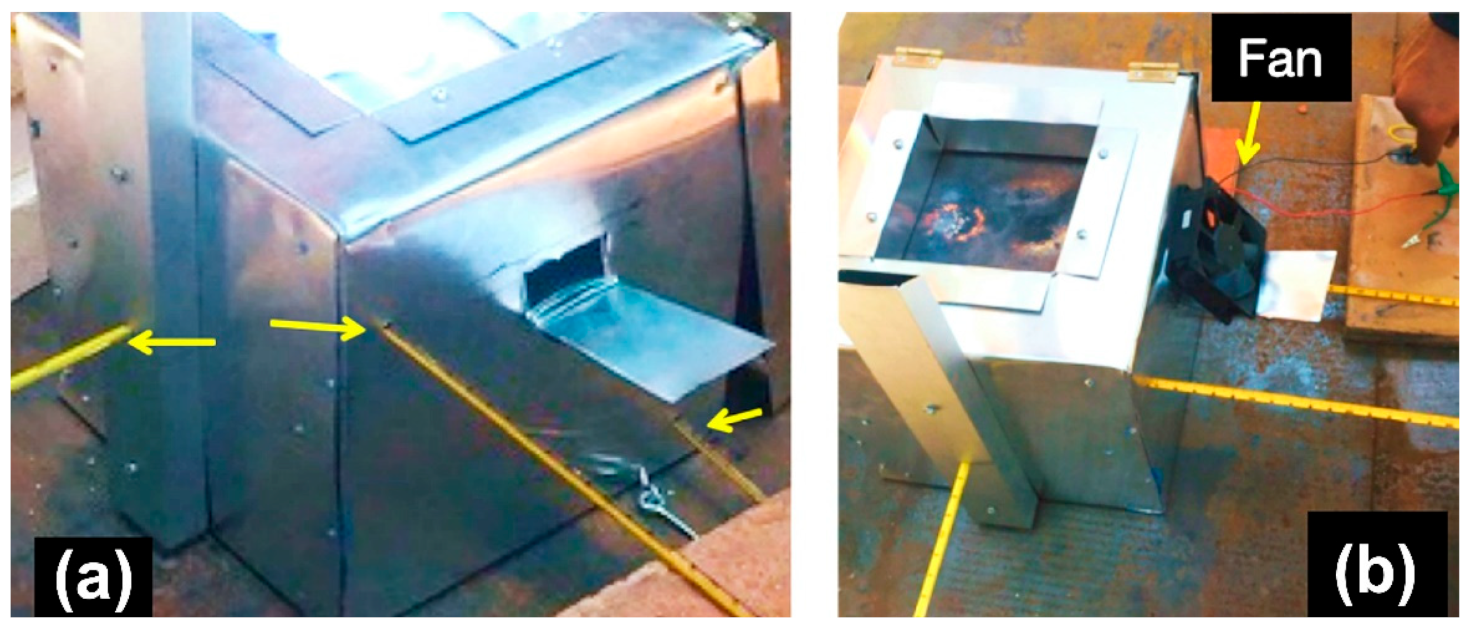
2.2. Determination of the Processes, Design, and Manufacture of the Prototype to Soften and Cut the Purges
3. Results and Discussion
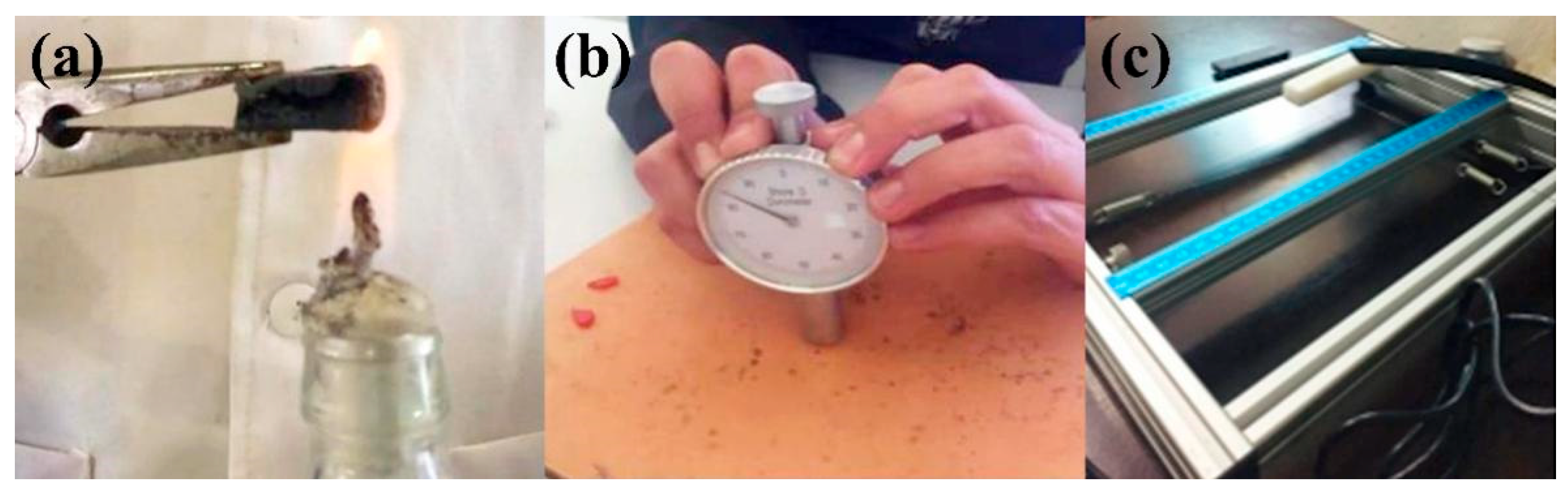
3.1. Higher Frequency Purges and Flame Test
3.2. Softening and Cutting Initial Tests
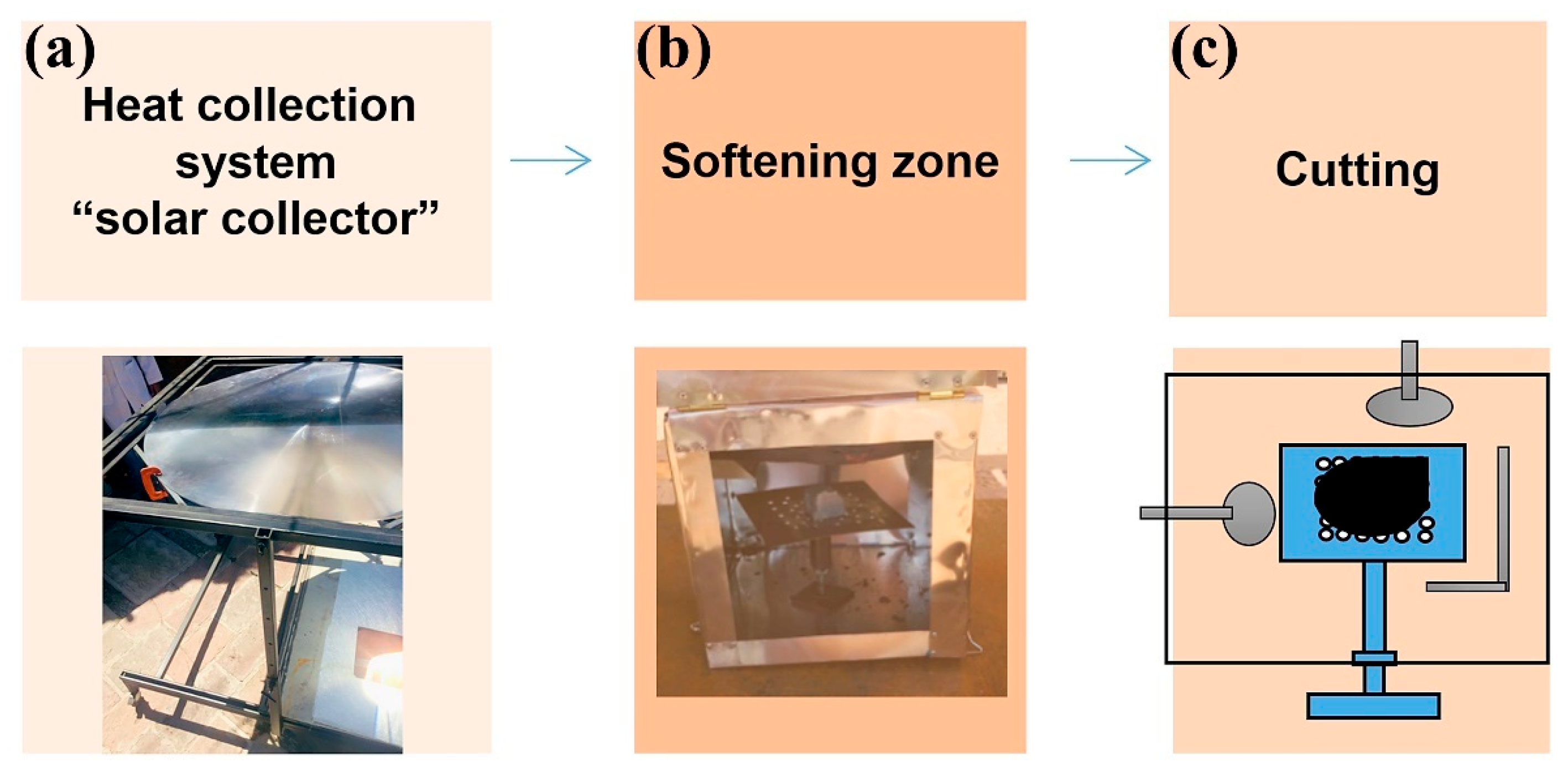
3.3. Process Design and Equipment
- (1)
- Heat collection system (“solar collector”). The purpose is to convert solar radiation into heat.
- (2)
- Softening zone. The purpose is to soften the purges and maintain the temperature reached for this purpose.
- (3)
- Cutting. Once the purges have been softened, the purpose of this last stage is to cut them off.
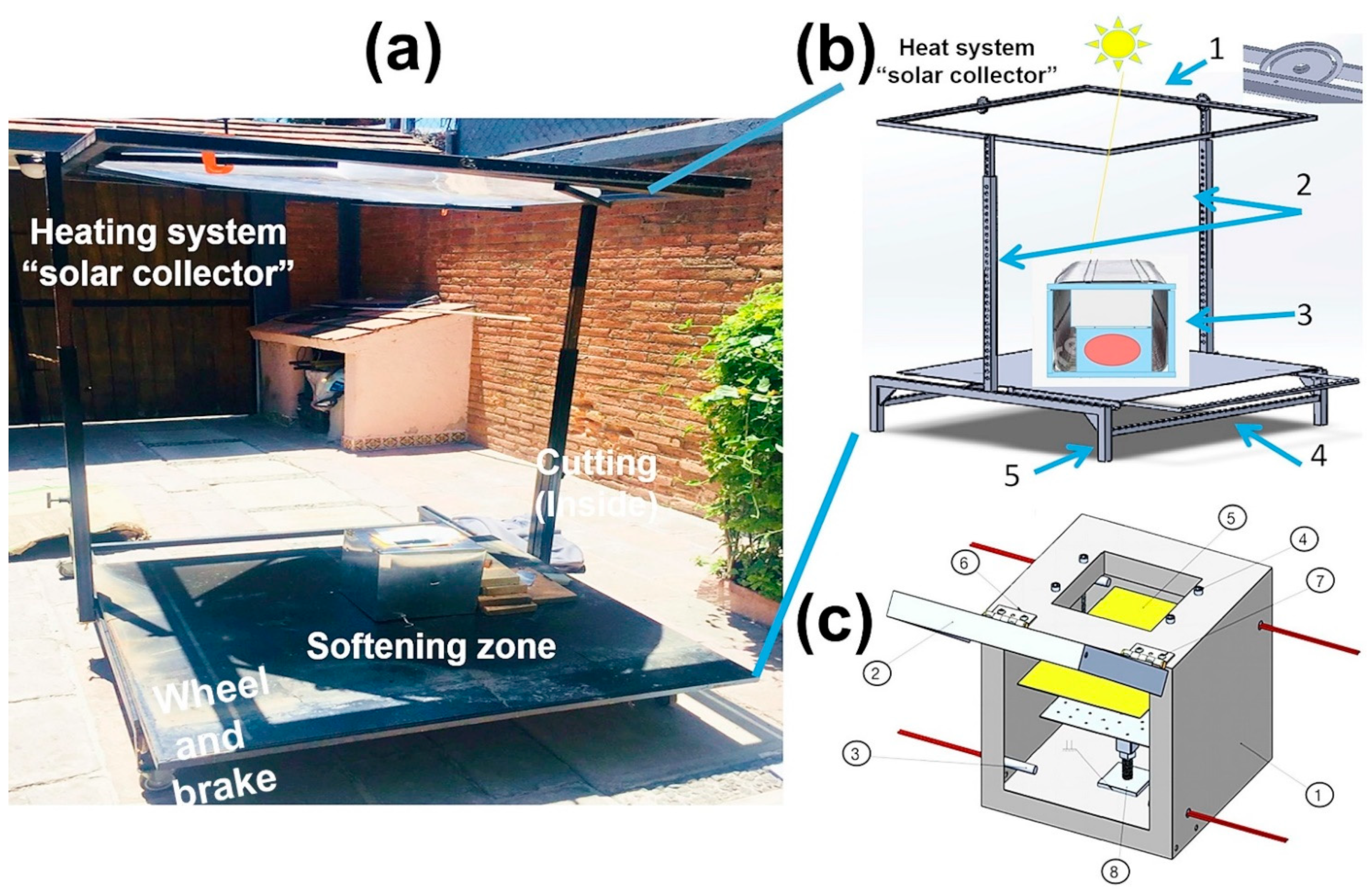
3.4. Heat Collection System (“Solar Collector”)
3.4.1. System Modeling and Construction
- (1)
- Lens support consists of two frames. The inner frame supports the lens and modifies its inclination angle, referencing the position perpendicular to the height posts. The outer frame gives the lens sun-tracking capabilities.
- (2)
- The design comprises two lateral posts, each comprising two rectangular tubes (one inside the other) that allow movement to achieve different lens heights relative to the sample. In addition, adjustment holes are spaced one inch apart for a total of twenty-six. Thus, a wide range of heights can be achieved.
- (3)
- Plate where the softening zone was located.
- (4)
- This plate incorporates a manual sliding system that allows it to be removed from the focus for user safety.
- (5)
- The device supports have swivel wheels with a braking system that moves and stops the device.
3.4.2. Softening Zone
3.4.3. Evaluating the Most Relevant Components of the Softening Zone
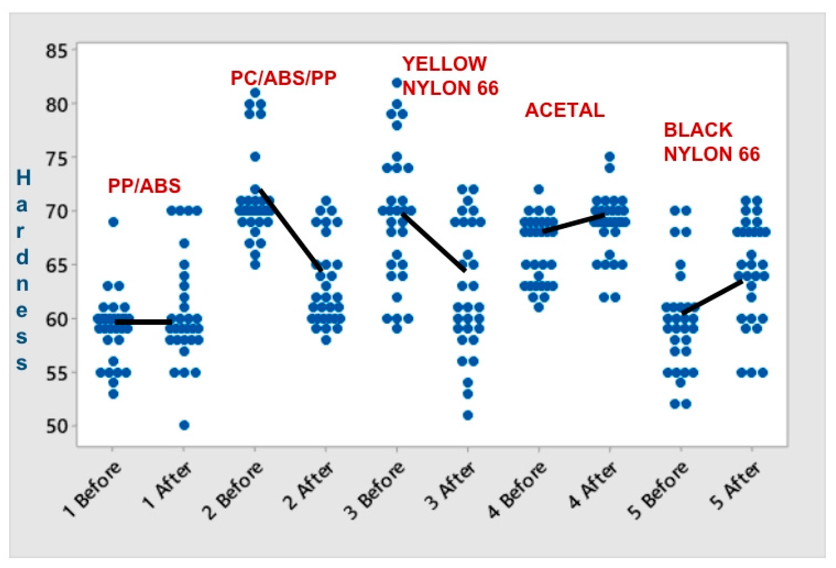
3.5. Hardness Testing
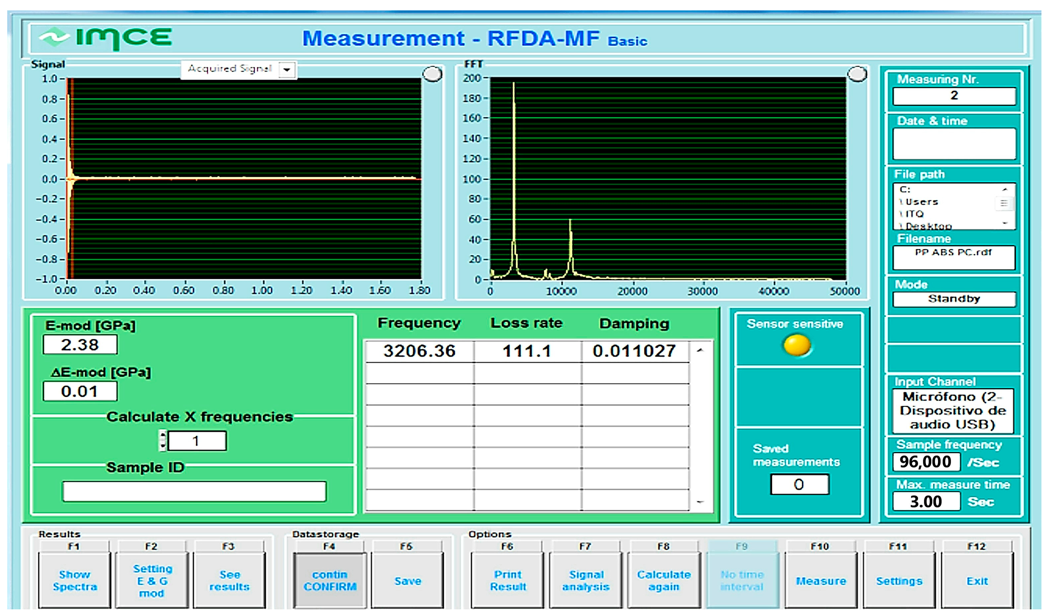
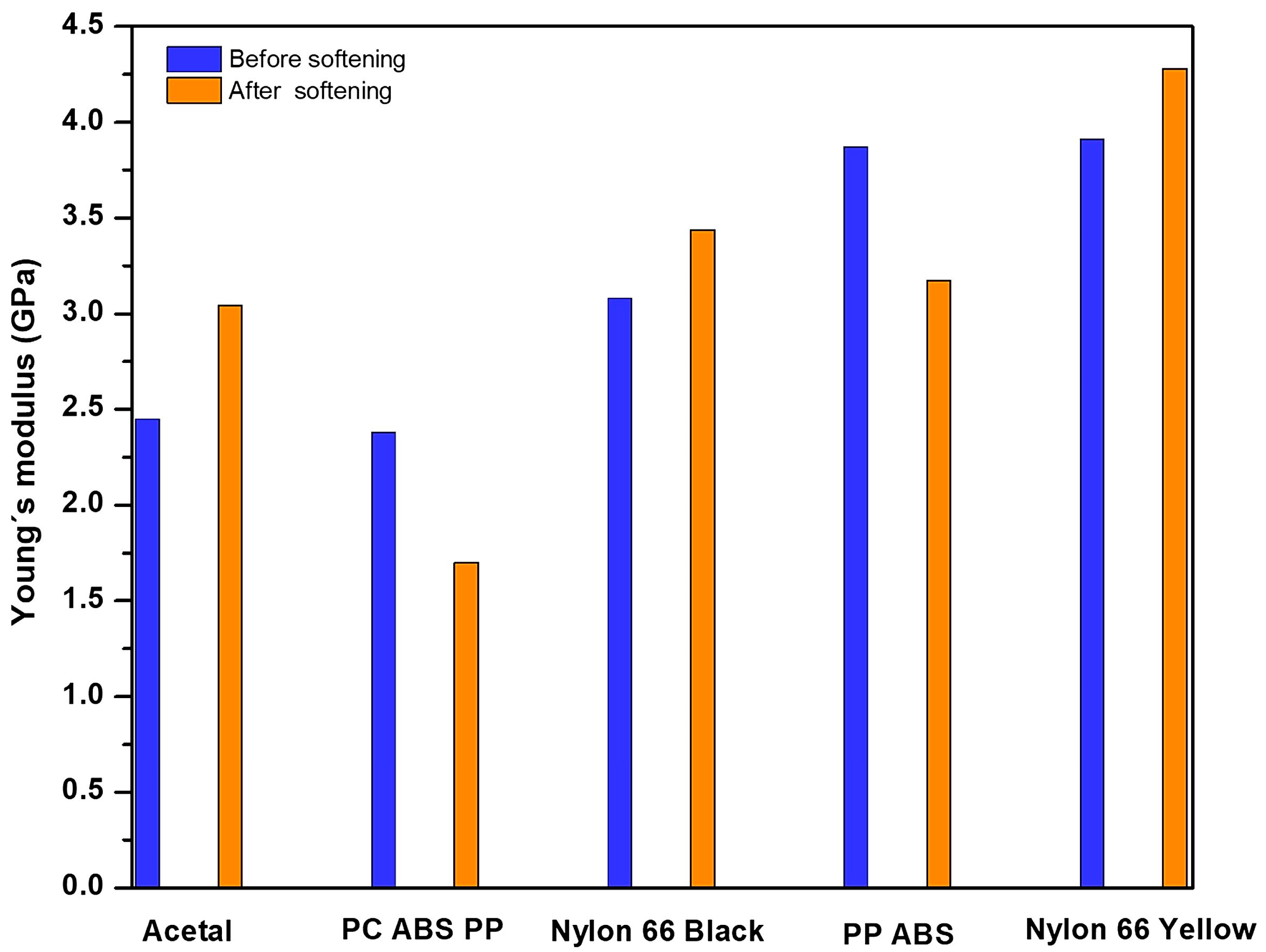
3.6. Young’s Module
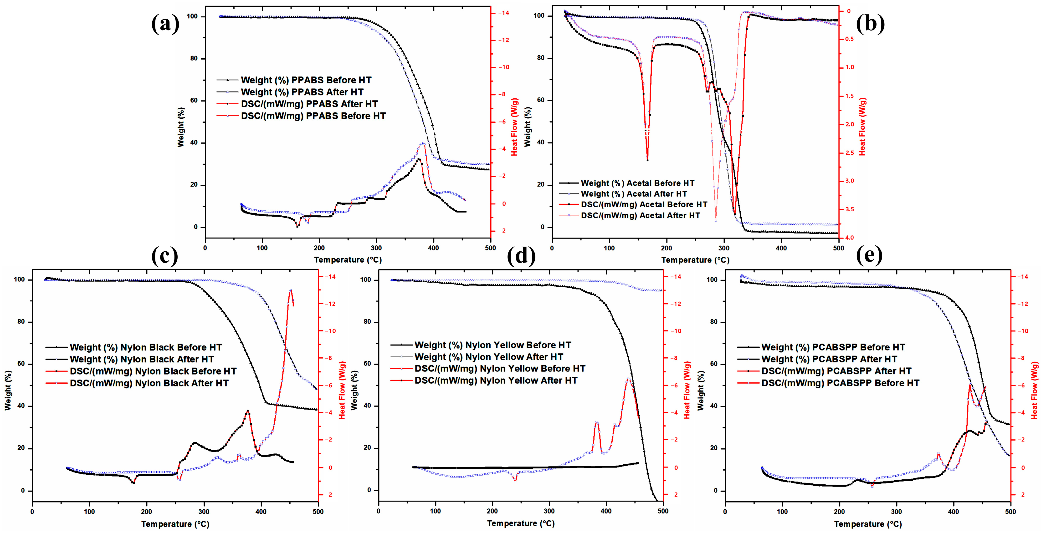
3.7. DSC and TGA Analyses
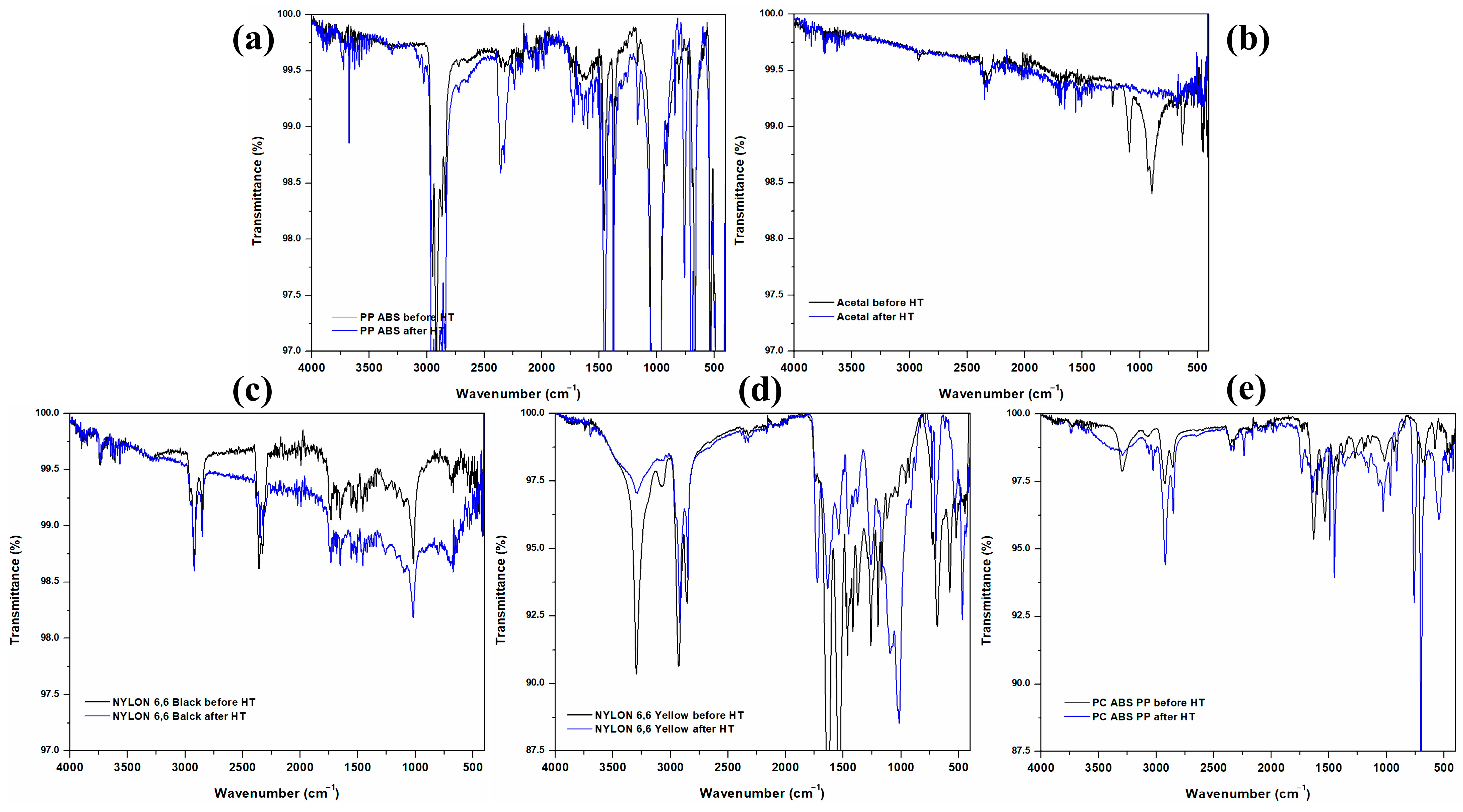
3.8. FT-IR Analyses
4. Conclusions
Author Contributions
Funding
Institutional Review Board Statement
Data Availability Statement
Acknowledgments
Conflicts of Interest
References
- Gu, F.; Guo, J.; Zhang, W.; Summers, P.A.; Hall, P. From waste plastics to industrial raw materials: A life cycle assessment of mechanical plastic recycling practice based on a real-world case study. Sci. Total Environ. 2017, 601–602, 1192–1207. [Google Scholar] [CrossRef]
- Dorigato, A. Recycling of polymer blends. Adv. Ind. Eng. Polym. Res. 2021, 4, 53–69. [Google Scholar] [CrossRef]
- Fredi, G.; Dorigato, A. Recycling of bioplastic waste: A review. Adv. Ind. Eng. Polym. Res. 2021, 4, 159–177. [Google Scholar] [CrossRef]
- Chanda, M. Chemical aspects of polymer recycling. Adv. Ind. Eng. Polym. Res. 2021, 4, 133–150. [Google Scholar] [CrossRef]
- Zhao, X.; Korey, M.; Li, K.; Copenhaver, K.; Tekinalp, H.; Celik, S.; Kalaitzidou, K.; Ruan, R.; Ragauskas, A.J.; Ozcan, S. Plastic waste upcycling toward a circular economy. Chem. Eng. J. 2022, 428, 131928. [Google Scholar] [CrossRef]
- Johansen, M.R.; Christensen, T.B.; Ramos, T.M.; Syberg, K. A review of the plastic value chain from a circular economy perspective. J. Environ. Manag. 2022, 302, 113975. [Google Scholar] [CrossRef]
- Mostofi Sarkari, N.; Ayar, P.; Hatefi Oskouei, M.; Karimian Khosrowshahi, F.; Mohseni, M. Silane crosslinkable polyethylene waste as bitumen modifier: A new fortunate destiny by in time recycling of thermoplastic waste before conversion to thermoset end-of-life unrecyclable polymer. Constr. Build. Mater. 2021, 287, 122999. [Google Scholar] [CrossRef]
- Martínez-López, M.; Martínez-Barrera, G.; Salgado-Delgado, R.; Gencel, O. Recycling polypropylene and polyethylene wastes in production of polyester based polymer mortars. Constr. Build. Mater. 2021, 274, 121487. [Google Scholar] [CrossRef]
- Eskander, S.B.; Saleh, H.M.; Tawfik, M.E.; Bayoumi, T.A. Towards potential applications of cement-polymer composites based on recycled polystyrene foam wastes on construction fields: Impact of exposure to water ecologies. Case Stud. Constr. Mater. 2021, 15, e00664. [Google Scholar] [CrossRef]
- Jelcic Rukavina, M.; Baricevic, A.; Serdar, M.; Grubor, M. Study on the post-fire properties of concrete with recycled tyre polymer fibres. Cem. Concr. Compos. 2021, 123, 104184. [Google Scholar] [CrossRef]
- Suresh, M.; Pal, M. Utilization of recycled concrete wastes and latex polymer for sustainable road construction. Mater. Today Proc. 2021, 47, 4171–4176. [Google Scholar] [CrossRef]
- Wathiq Hammodat, W. Investigate road performance using polymer modified concrete. Mater. Today Proc. 2021, 42, 2089–2094. [Google Scholar] [CrossRef]
- Varun, B.K.; Anila Kumar, C.P. Strength characteristics of polymer modified high volume fly ash concrete. Mater. Today Proc. 2021, 46, 285–288. [Google Scholar] [CrossRef]
- Viscione, N.; Veropalumbo, R.; Oreto, C.; Biancardo, S.A.; Abbondati, F.; Russo, F. Additional procedures for characterizing the performance of recycled polymer modified asphalt mixtures. Measurement 2022, 187, 110238. [Google Scholar] [CrossRef]
- Kazemi, M.; Fini, E.H. State of the art in the application of functionalized waste polymers in the built environment. Resour. Conserv. Recycl. 2022, 177, 105967. [Google Scholar] [CrossRef]
- Gu, L.; Ozbakkaloglu, T. Use of recycled plastics in concrete: A critical review. Waste Manag. 2016, 51, 19–42. [Google Scholar] [CrossRef]
- Ahmad, J.; Majdi, A.; Babeker Elhag, A.; Deifalla, A.F.; Soomro, M.; Isleem, H.F.; Qaidi, S. A Step towards Sustainable Concrete with Substitution of Plastic Waste in Concrete: Overview on Mechanical, Durability and Microstructure Analysis. Crystals 2022, 12, 944. [Google Scholar] [CrossRef]
- Qaidi, S.; Al-Kamaki, Y.; Hakeem, I.; Dulaimi, A.F.; Özkılıç, Y.; Sabri, M.; Sergeev, V. Investigation of the physical-mechanical properties and durability of high-strength concrete with recycled PET as a partial replacement for fine aggregates. Front. Mater. 2023, 10, 1101146. [Google Scholar] [CrossRef]
- Vila-Cortavitarte, M.; Lastra-González, P.; Calzada-Pérez, M.Á.; Indacoechea-Vega, I. Analysis of the influence of using recycled polystyrene as a substitute for bitumen in the behaviour of asphalt concrete mixtures. J. Clean. Prod. 2018, 170, 1279–1287. [Google Scholar] [CrossRef]
- Chaukura, N.; Gwenzi, W.; Bunhu, T.; Ruziwa, D.T.; Pumure, I. Potential uses and value-added products derived from waste polystyrene in developing countries: A review. Resour. Conserv. Recycl. 2016, 107, 157–165. [Google Scholar] [CrossRef]
- Liguori, F.; Moreno-Marrodán, C.; Barbaro, P. Valorisation of plastic waste via metal-catalysed depolymerisation. Beilstein J. Org. Chem. 2021, 17, 589–621. [Google Scholar] [CrossRef]
- Kosloski-Oh, S.C.; Wood, Z.A.; Manjarrez, Y.; de los Rios, J.P.; Fieser, M.E. Catalytic methods for chemical recycling or upcycling of commercial polymers. Mater. Horiz. 2021, 8, 1084–1129. [Google Scholar] [CrossRef] [PubMed]
- Zhang, F.; Zhao, Y.; Wang, D.; Yan, M.; Zhang, J.; Zhang, P.; Ding, T.; Chen, L.; Chen, C. Current technologies for plastic waste treatment: A review. J. Clean. Prod. 2021, 282, 124523. [Google Scholar] [CrossRef]
- Singh, N.; Hui, D.; Singh, R.; Ahuja, I.P.S.; Feo, L.; Fraternali, F. Recycling of plastic solid waste: A state of art review and future applications. Compos. Part B Eng. 2017, 115, 409–422. [Google Scholar] [CrossRef]
- Chohan, J.S.; Singh, R. Thermosetting Polymers: A Review on Primary, Secondary, Tertiary and Quaternary Recycling. In Encyclopedia of Materials: Plastics and Polymers; Elsevier: Amsterdam, The Netherlands, 2022; pp. 603–610. [Google Scholar]
- Kumar, S.; Singh, R. Primary and Secondary Recycling of Thermoplastics: A Review. In Encyclopedia of Materials: Plastics and Polymers; Elsevier: Amsterdam, The Netherlands, 2022; pp. 471–477. [Google Scholar]
- Delva, L.; Hubo, S.; Cardon, L.; Ragaert, K. On the role of flame retardants in mechanical recycling of solid plastic waste. Waste Manag. 2018, 82, 198–206. [Google Scholar] [CrossRef] [PubMed]
- Huang, J.; Veksha, A.; Chan, W.P.; Lisak, G. Support effects on thermocatalytic pyrolysis-reforming of polyethylene over impregnated Ni catalysts. Appl. Catal. A Gen. 2021, 622, 118222. [Google Scholar] [CrossRef]
- Li, N.; Liu, H.; Cheng, Z.; Yan, B.; Chen, G.; Wang, S. Conversion of plastic waste into fuels: A critical review. J. Hazard. Mater. 2022, 424, 127460. [Google Scholar] [CrossRef] [PubMed]
- Garcia, J.M.; Robertson, M.L. The future of plastics recycling. Science 2017, 358, 870–872. [Google Scholar] [CrossRef] [PubMed]
- Vollmer, I.; Jenks, M.J.F.; Roelands, M.C.P.; White, R.J.; Harmelen, T.; Wild, P.; Laan, G.P.; Meirer, F.; Keurentjes, J.T.F.; Weckhuysen, B.M. Beyond Mechanical Recycling: Giving New Life to Plastic Waste. Angew. Chem. Int. Ed. 2020, 59, 15402–15423. [Google Scholar] [CrossRef]
- Arandes, J.; Bilbao, J.; López, D. Reciclado de residuos plásticos. Rev. Iberoam. Polímeros 2004, 5, 28–45. [Google Scholar]
- Ragaert, K.; Delva, L.; Van Geem, K. Mechanical and chemical recycling of solid plastic waste. Waste Manag. 2017, 69, 24–58. [Google Scholar] [CrossRef] [PubMed]
- Thakur, S.; Verma, A.; Sharma, B.; Chaudhary, J.; Tamulevicius, S.; Thakur, V.K. Recent developments in recycling of polystyrene based plastics. Curr. Opin. Green Sustain. Chem. 2018, 13, 32–38. [Google Scholar] [CrossRef]
- Yang, Z.; Lü, F.; Zhang, H.; Wang, W.; Shao, L.; Ye, J.; He, P. Is incineration the terminator of plastics and microplastics? J. Hazard. Mater. 2021, 401, 123429. [Google Scholar] [CrossRef] [PubMed]
- Shen, M.; Hu, T.; Huang, W.; Song, B.; Qin, M.; Yi, H.; Zeng, G.; Zhang, Y. Can incineration completely eliminate plastic wastes? An investigation of microplastics and heavy metals in the bottom ash and fly ash from an incineration plant. Sci. Total Environ. 2021, 779, 146528. [Google Scholar] [CrossRef]
- Lai, Y.; Dong, L.; Sheng, X.; Li, Q.; Li, P.; Hao, Z.; Yu, S.; Liu, J. Swelling-Induced Fragmentation and Polymer Leakage of Nanoplastics in Seawater. Environ. Sci. Technol. 2022, 56, 17694–17701. [Google Scholar] [CrossRef]
- Guo, Y.; Xia, X.; Ruan, J.; Wang, Y.; Zhang, J.; LeBlanc, G.A.; An, L. Ignored microplastic sources from plastic bottle recycling. Sci. Total Environ. 2022, 838, 156038. [Google Scholar] [CrossRef]
- Huang, Q.; Cheng, Z.; Yang, C.; Wang, H.; Zhu, N.; Cao, X.; Lou, Z. Booming microplastics generation in landfill: An exponential evolution process under temporal pattern. Water Res. 2022, 223, 119035. [Google Scholar] [CrossRef]
- Thakur, S.; Chaudhary, J.; Singh, P.; Alsanie, W.F.; Grammatikos, S.A.; Thakur, V.K. Synthesis of Bio-based monomers and polymers using microbes for a sustainable bioeconomy. Bioresour. Technol. 2022, 344, 126156. [Google Scholar] [CrossRef]
- Miri, S.; Saini, R.; Davoodi, S.M.; Pulicharla, R.; Brar, S.K.; Magdouli, S. Biodegradation of microplastics: Better late than never. Chemosphere 2022, 286, 131670. [Google Scholar] [CrossRef]
- Zhang, Q.; Deng, Y.; Shi, C.-Y.; Feringa, B.L.; Tian, H.; Qu, D.-H. Dual closed-loop chemical recycling of synthetic polymers by intrinsically reconfigurable poly(disulfides). Matter 2021, 4, 1352–1364. [Google Scholar] [CrossRef]
- Vimala, P.P.; Mathew, L. Biodegradation of Polyethylene Using Bacillus Subtilis. Procedia Technol. 2016, 24, 232–239. [Google Scholar] [CrossRef]
- Restrepo-Flórez, J.-M.; Bassi, A.; Thompson, M.R. Microbial degradation and deterioration of polyethylene—A review. Int. Biodeterior. Biodegrad. 2014, 88, 83–90. [Google Scholar] [CrossRef]
- Nowak, B.; Pająk, J.; Drozd-Bratkowicz, M.; Rymarz, G. Microorganisms participating in the biodegradation of modified polyethylene films in different soils under laboratory conditions. Int. Biodeterior. Biodegrad. 2011, 65, 757–767. [Google Scholar] [CrossRef]
- Mohan, A.J.; Sekhar, V.C.; Bhaskar, T.; Nampoothiri, K.M. Microbial assisted High Impact Polystyrene (HIPS) degradation. Bioresour. Technol. 2016, 213, 204–207. [Google Scholar] [CrossRef] [PubMed]
- ISO 868:2003; Plastics and Ebonite, Determination of Indentation Hardness by Means of a Durometer (Shore Hardness). International Organization for Standardization (ISO): Geneva, Switzerland, 2003.
- ASTM E1876-22; Standard Test Method for Dynamic Young’s Modulus, Shear Modulus, and Poisson’s Ratio by Impulse Excitation of Vibration. ASTM International: West Conshohocken, PA, USA, 2022; pp. 1–19.
- ISO 11358-1:2002; Plastics, Thermogravimetry (TG) of Polymers, Part 1: General Principles. International Organization for Standardization (ISO): Geneva, Switzerland, 2022.
- Muraleedharan, M.; Singh, H.; Udayakumar, M.; Suresh, S. Modified active solar distillation system employing directly absorbing Therminol 55–Al2O3 nano heat transfer fluid and Fresnel lens concentrator. Desalination 2019, 457, 32–38. [Google Scholar] [CrossRef]
- Borode, A.; Ahmed, N.; Olubambi, P. A review of solar collectors using carbon-based nanofluids. J. Clean. Prod. 2019, 241, 118311. [Google Scholar] [CrossRef]
- Borode, A.O.; Ahmed, N.A.; Olubambi, P.A. Surfactant-aided dispersion of carbon nanomaterials in aqueous solution. Phys. Fluids 2019, 31, 071301. [Google Scholar] [CrossRef]
- Yi, Y.; Salonitis, K.; Tsoutsanis, P.; Litos, L.; Patsavelas, J. Improving the Curing Cycle Time through the Numerical Modeling of air Flow in Industrial Continuous Convection Ovens. Procedia CIRP 2017, 63, 499–504. [Google Scholar] [CrossRef]
- Suman, S.; Khan, M.K.; Pathak, M. Performance enhancement of solar collectors—A review. Renew. Sustain. Energy Rev. 2015, 49, 192–210. [Google Scholar] [CrossRef]
- Sosa Domínguez, A.; Pérez Bueno, J.J.J.; Zamudio Torres, I.; Mendoza López, M.L.L.; Sosa Domínguez, A. Corrosion Study of Electroless Deposited Nickel-Phosphorus Solar Absorber Coatings on Carbon Steel. Int. J. Electrochem. Sci. 2017, 12, 2987–3000. [Google Scholar] [CrossRef]
- Sosa Domínguez, A.; Pérez Bueno, J.J.J.; Zamudio Torres, I.; Mendoza López, M.L.L. Characterization and corrosion resistance of electroless black Ni-P coatings of double black layer on carbon steel. Surf. Coat. Technol. 2017, 326, 192–199. [Google Scholar] [CrossRef]
- Bueno, J.d.J.P.; Rojas, E.R.; Hernandez, J.M.; López, M.L.M.; Esquivel, R.A.C. Copper Black Coatings for the Absorption of Solar Concentration with an APPJ SiO2 Super-Hydrophobic Protection. Int. J. Environ. Sustain. Green Technol. 2020, 12, 76–87. [Google Scholar] [CrossRef]
- Herrera-Zamora, D.M.M.; Lizama-Tzec, F.I.I.; Santos-González, I.; Rodríguez-Carvajal, R.A.A.; García-Valladares, O.; Arés-Muzio, O.; Oskam, G. Electrodeposited black cobalt selective coatings for application in solar thermal collectors: Fabrication, characterization, and stability. Sol. Energy 2020, 207, 1132–1145. [Google Scholar] [CrossRef]
- Wang, X.; Liu, D.; Liu, X.; He, Y. Graphene oxide stabilized carbon nanotube-water nanofluids for direct absorption solar collectors. IOP Conf. Ser. Mater. Sci. Eng. 2019, 556, 012037. [Google Scholar] [CrossRef]
- Uscanga Olea, M.A.; Pérez Bueno, J.d.J.; Pérez Maldonado, A.X. Nanometric and surface properties of semiconductors correlated to photocatalysis and photoelectrocatalysis applied to organic pollutants—A review. J. Environ. Chem. Eng. 2021, 9, 106480. [Google Scholar] [CrossRef]
- Cacho, L.M.; de Jesús Pérez Bueno, J.; Vong, Y.M.; Stremsdoerfer, G. Effect of swelling of chemical reagents and the sulfuric-chromic acid bath on surface texturizing of poly(acrylonitrile-butadiene-styrene). Acta Chim. Slov. 2019, 66, 638–647. [Google Scholar] [CrossRef]
- Magallón Cacho, L.; Pérez Bueno, J.J.; Meas Vong, Y.; Stremsdoerfer, G.; Espinoza Beltrán, F.J.; Martínez Vega, J. Novel green process to modify ABS surface before its metallization: Optophysic treatment. J. Coat. Technol. Res. 2015, 12, 313–323. [Google Scholar] [CrossRef]
- Magallón-Cacho, L.; Pérez-Bueno, J.J.; Meas-Vong, Y.; Stremsdoerfer, G.; Espinoza-Beltrán, F.J. Surface modification of acrylonitrile-butadiene-styrene (ABS) with heterogeneous photocatalysis (TiO2) for the substitution of the etching stage in the electroless process. Surf. Coat. Technol. 2011, 206, 1410–1415. [Google Scholar] [CrossRef]


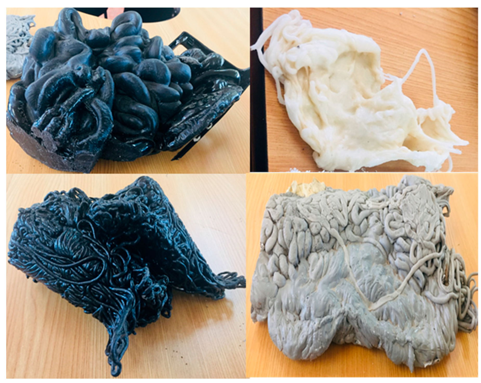
| Polymers | Physical Description | Observations | Image |
|---|---|---|---|
| PP-ABS | Gray with many marked lines | The material quickly deforms, the flame is yellow and blue, bubbles, and becomes rubbery but does not drip, and carbonizes in its walls. As a result, it can be stretched and makes almost no smoke. |  |
| PC-ABS-PP | Two shades of black (one glossy and one opaque) | Quickly begins to burn and deform. The flame is yellow, it causes fumes of black smoke, and has a marked odor. It becomes rubbery, but drips cannot be stretched and carbonized. |  |
| Nylon 66 yellow | Yellow with many marked lines | It takes time to begin to burn and change its form. Then it bubbles, causes a small amount of fumes, the flame is yellow and blue, becomes rubbery but does not drip, can be stretched, and gets carbonized at the end. |  |
| Acetal (polyoxymethylene, POM) | White with many grains | Quickly begins to burn and deform. The flame is yellow and blue, and it causes a small amount of fumes. It has a marked odor. It bubbles a lot but does not drip, can be stretched, becomes rubbery, and gets carbonized at the end. |  |
| Nylon 66/black with fillers | Spaghetti-shaped black | It takes time to begin to burn and change its form. It bubbles but does not drip, making almost no smoke. The flame is yellow and blue, hardly stretched, and nearly no carbonization at the end. |  |
| Polymers | Weight (g) | Temperature (°C) | Time (min) | Observations |
|---|---|---|---|---|
| PP-ABS | 16.7 | 250 | 20 | It can be easily cut, and it can be stretched, but it tends to become rubbery. |
| PC-ABS-PP | 52.99 | 250 | 20 | It can be easily cut and stretched. |
| Nylon 66 yellow | 6.64 | 250 | 20 | It cools down very fast and hardens. It can be stretched. Changes to a dark color. It is relatively difficult to cut and has a sandy consistency. |
| Acetal (polyoxymethylene, POM) | 29.88 | 300 | 45 | It cools down very fast and hardens. It can be stretched. Changes to a dark color. Difficult to cut. |
| Nylon 66/black with fillers | 19.63 | 300 | 50 | It cools down very fast and hardens. It can be stretched but has a dusty consistency. |
| Requirements | Answer |
|---|---|
| Increase or decrease the diameter of the focus | Height adjustment mechanism |
| Adjusted to the position of the sun | Angle adjustment mechanism |
| A softening zone | Sample tray |
| Easy to move | Drive wheels and brake |
| No risk of the lens falling off | Padded retainer |
| Samples can be inserted and removed without risk of burns | Handle—endless screw system or rails |
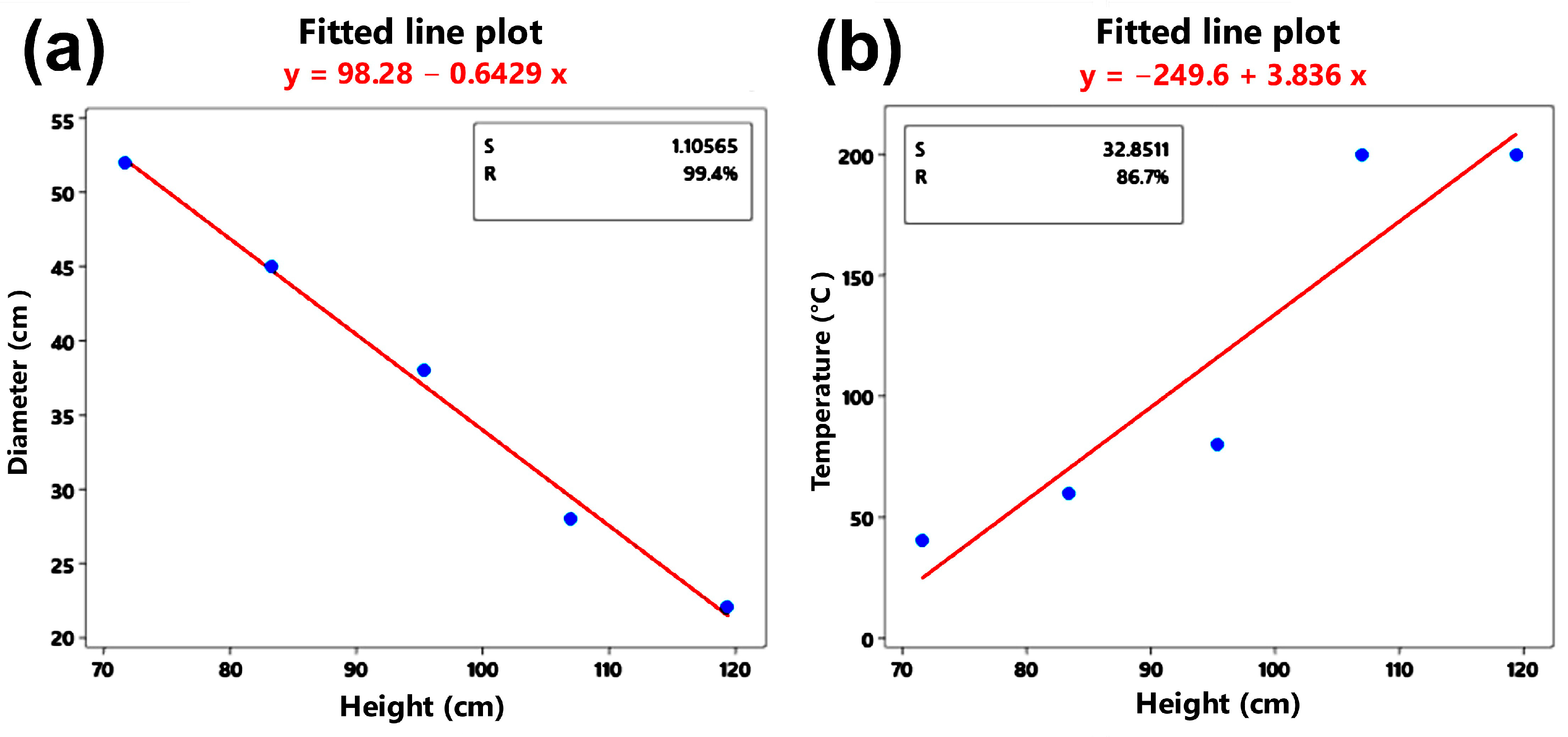
| Height (cm) | Diameter (cm) | Temp. (°C) |
|---|---|---|
| 71.5 | 52 | 40 |
| 83.3 | 45 | 60 |
| 95.3 | 38 | 80 |
| 107 | 28 | 200 |
| 119.5 | 22 | 200 |
| Source | GL | MC | F | P | GL | SC | MC | F | P |
|---|---|---|---|---|---|---|---|---|---|
| Regression | 1 | 21,082 | 19.54 | 0.022 | 1 | 592.333 | 592.333 | 484.54 | 0 |
| Height [cm] | 1 | 21,082 | 19.54 | 0.022 | |||||
| Error | 3 | 1079 | 3 | 3.667 | 1.222 | ||||
| Total | 4 | 4 | 596 | ||||||
| Source | GL | MC | F | P | 3 | 3.667 | 1.222 |
| Factors | 2 | Base design | 2, 4 | Factor | Level + | Level − |
| Test runs | 8 | Replica | 2 | Fan | With | Without |
| Blocks | 1 | Center points (total) | 0 | Absorbing material | Copper | Steel sheet |
| Test Run | Fan | Receiving Sheet | Y1 | Y2 | Y3 | Y4 | Y5 |
|---|---|---|---|---|---|---|---|
| 1 | No | galvanized | 74 | 98 | 79 | 84 | 90 |
| 2 | Yes | galvanized | 74 | 78 | 72 | 72 | 82 |
| 3 | No | copper | 110 | 130 | 104 | 90 | 106 |
| 4 | Yes | galvanized | 76 | 76 | 76 | 80 | 90 |
| 5 | Yes | copper | 92 | 80 | 80 | 72 | 80 |
| 6 | Yes | copper | 90 | 82 | 80 | 74 | 80 |
| 7 | No | copper | 120 | 130 | 110 | 88 | 100 |
| 8 | No | galvanized | 86 | 104 | 86 | 94 | 100 |
| Source | DF | Adj SS | Adj MS | F-Value | p-Value |
|---|---|---|---|---|---|
| Model | 3 | 1901.5 | 633.83 | 20.12 | 0.007 |
| Linear | 2 | 1721 | 860.5 | 27.32 | 0.005 |
| Fan | 1 | 420.5 | 420.5 | 13.35 | 0.022 |
| Receiving sheet | 1 | 1300.5 | 1300.5 | 41.29 | 0.003 |
| 2-Way Interactions | 1 | 180.5 | 180.5 | 5.73 | 0.075 |
| Fan * receiving sheet | 1 | 180.5 | 180.5 | 5.73 | 0.075 |
| Error | 4 | 126 | 31.5 | ||
| Total | 7 | 2027.5 |
| Y | Fan X1 | Material X2 | Interaction | X with More Influence | Best Combination | |
|---|---|---|---|---|---|---|
| X1 | X2 | |||||
| Y1= Upper right position temperature | Yes | Yes | No | Material | Without | Copper |
| Y2 = Central position temperature | Yes | Yes | Yes | Fan | Without | Copper |
| Y3 = Upper left position temperature | Yes | Yes | Yes | Fan | Without | Copper |
| Y4 = Lower left position temperature | Yes | No | Yes | Fan | Without | Same |
| Y5 = Lower right position temperature | Yes | No | No | Fan | Without | Same |
| Polymers | Average Hardness before Heating | Average Hardness after Heating–Cooling | Conclusions of the Average Analyses | Conclusions of the Variance Analyses |
|---|---|---|---|---|
| PP-ABS | 59.03 | 60.6 | p-value = 0.149 No change | p-value = 0.115 No change |
| PC-ABS-PP | 71.33 | 63.23 | p-value = 0.00 Different after the heat decreases | p-value = 0.591 No change |
| Nylon 66 yellow | 69.53 | 62.63 | p-value = 0.001 Different after the heat decreases | p-value = 0.364 No change |
| Acetal | 66.37 | 68.67 | p-value = 0.005 Different after the heat increases | p-value = 0.218 No change |
| Nylon 66/black with fillers | 59.8 | 64.43 | p-value = 0.00 Different after the heat increases | p-value = 0.701 No change |
| Polymers | YM before | YM after | Comparative |
|---|---|---|---|
| PP-ABS | 3.88 (±0.02) | 3.17 (±0.01) | ↓ 18% |
| PC-ABS-PP | 2.38 (±0.001) | 1.70 (±0.001) | ↓ 28% |
| Nylon 66 yellow | 3.94 (±0.01) | 4.28 (±0.01) | ↑ 9% |
| Acetal (polyoxymethylene, POM) | 2.45 (±0.001) | 3.04 (±0.01) | ↑ 24% |
| Nylon 66/black with fillers | 3.08 (±0.001) | 3.45 (±0.005) | ↑ 12% |
Disclaimer/Publisher’s Note: The statements, opinions and data contained in all publications are solely those of the individual author(s) and contributor(s) and not of MDPI and/or the editor(s). MDPI and/or the editor(s) disclaim responsibility for any injury to people or property resulting from any ideas, methods, instructions or products referred to in the content. |
© 2024 by the authors. Licensee MDPI, Basel, Switzerland. This article is an open access article distributed under the terms and conditions of the Creative Commons Attribution (CC BY) license (https://creativecommons.org/licenses/by/4.0/).
Share and Cite
Plaza, M.G.; Mendoza López, M.L.; Pérez Bueno, J.d.J.; Pérez Meneses, J.; Maldonado Pérez, A.X. Polymer Waste Recycling of Injection Molding Purges with Softening for Cutting with Fresnel Solar Collector—A Real Problem Linked to Sustainability and the Circular Economy. Polymers 2024, 16, 1012. https://doi.org/10.3390/polym16071012
Plaza MG, Mendoza López ML, Pérez Bueno JdJ, Pérez Meneses J, Maldonado Pérez AX. Polymer Waste Recycling of Injection Molding Purges with Softening for Cutting with Fresnel Solar Collector—A Real Problem Linked to Sustainability and the Circular Economy. Polymers. 2024; 16(7):1012. https://doi.org/10.3390/polym16071012
Chicago/Turabian StylePlaza, Ma. Guadalupe, Maria Luisa Mendoza López, José de Jesús Pérez Bueno, Joaquín Pérez Meneses, and Alejandra Xochitl Maldonado Pérez. 2024. "Polymer Waste Recycling of Injection Molding Purges with Softening for Cutting with Fresnel Solar Collector—A Real Problem Linked to Sustainability and the Circular Economy" Polymers 16, no. 7: 1012. https://doi.org/10.3390/polym16071012