

Characterization of Exterior Parts for 3D-Printed Humanoid Robot Arm with Various Patterns and Thicknesses


Abstract
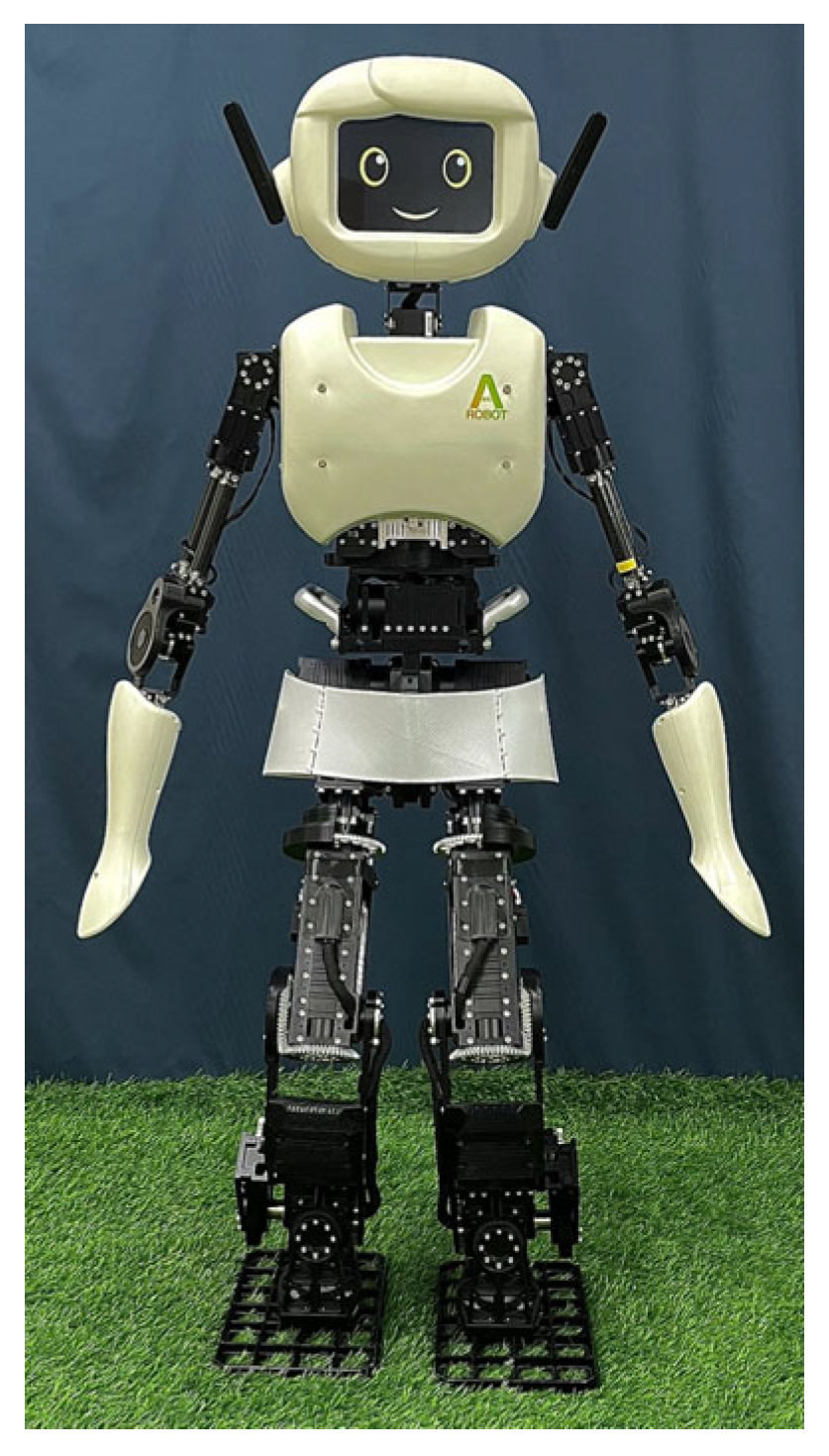
1. Introduction
2. Experimental Section
2.1. Materials
2.2. Preparation of 3D-Printed Forearm and Upper Arm with Three Different Thicknesses
2.3. Characterizations
2.3.1. Analysis of Slicing of 3D-Printed Humanoid Robot Arm with Various Patterns and Thicknesses
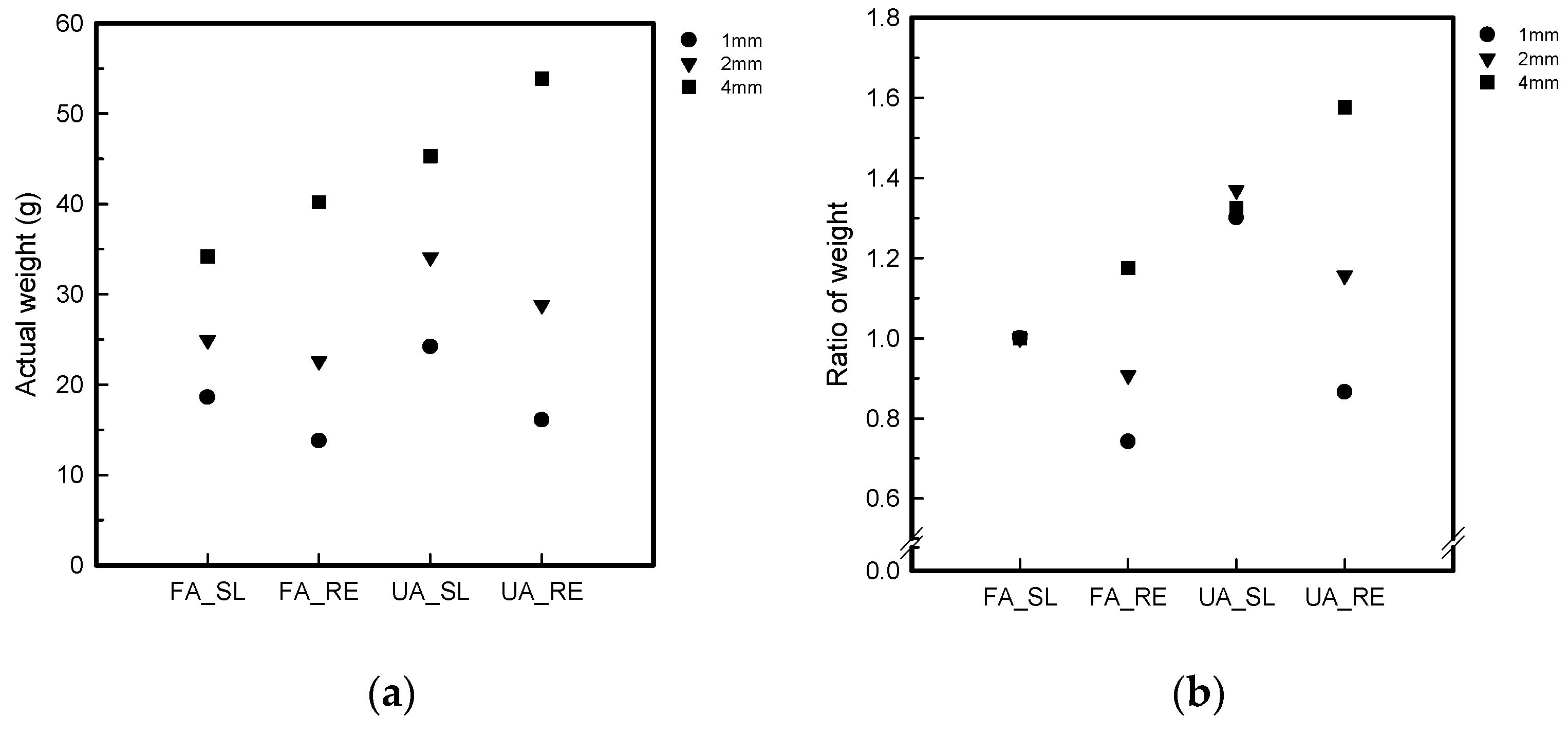
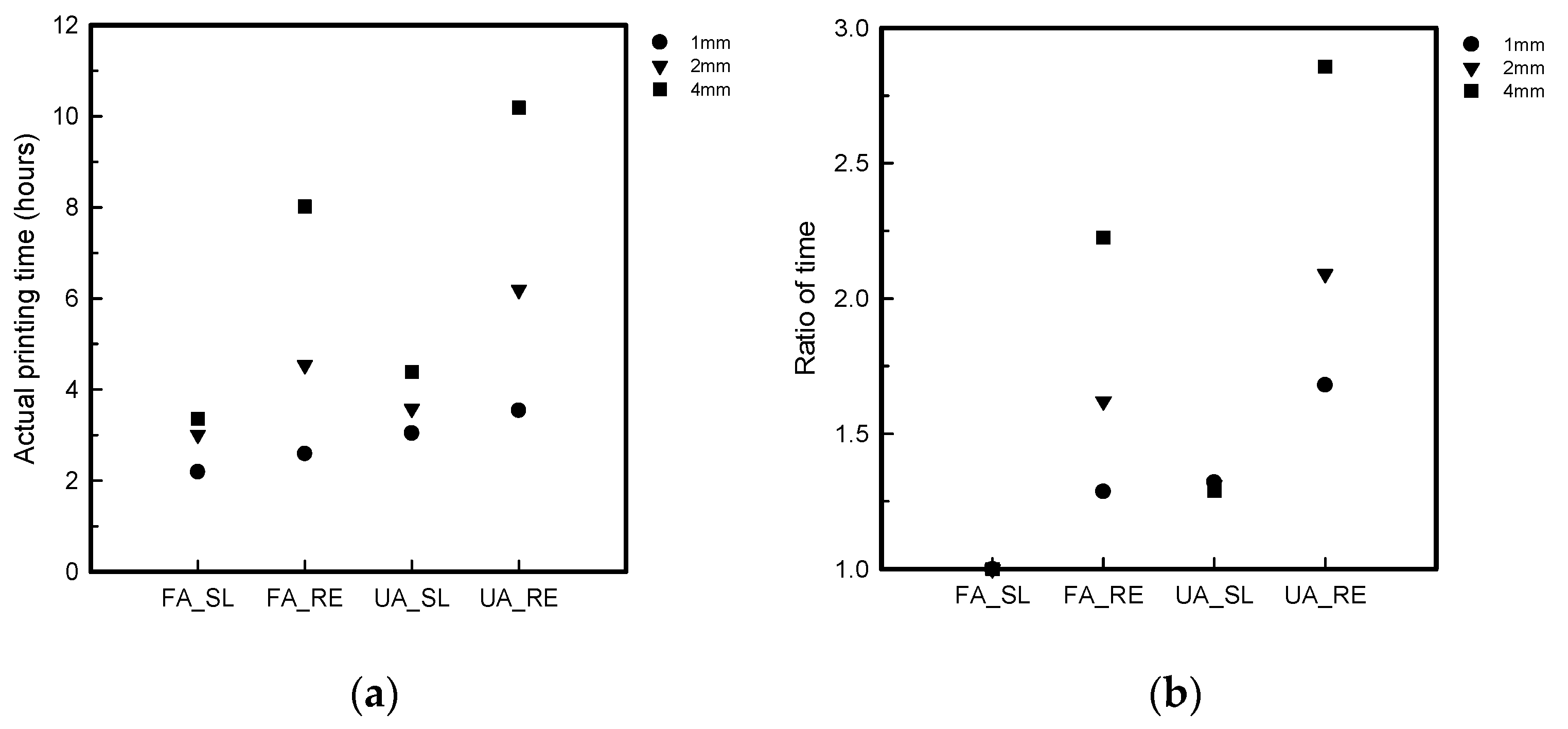
2.3.2. Actual Printing Time and Weight of 3D-Printed Humanoid Robot Arm with Various Patterns and Thicknesses
2.3.3. Mechanical Properties of 3D-Printed Humanoid Robot Arm with Various Patterns and Thicknesses
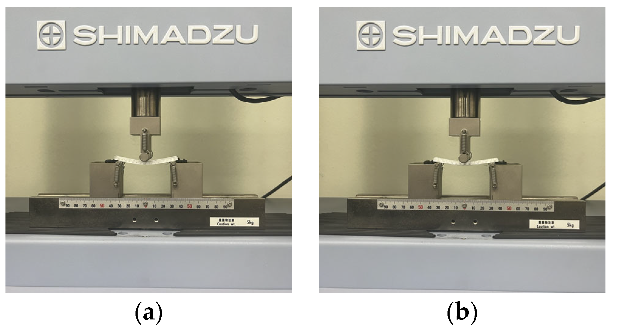
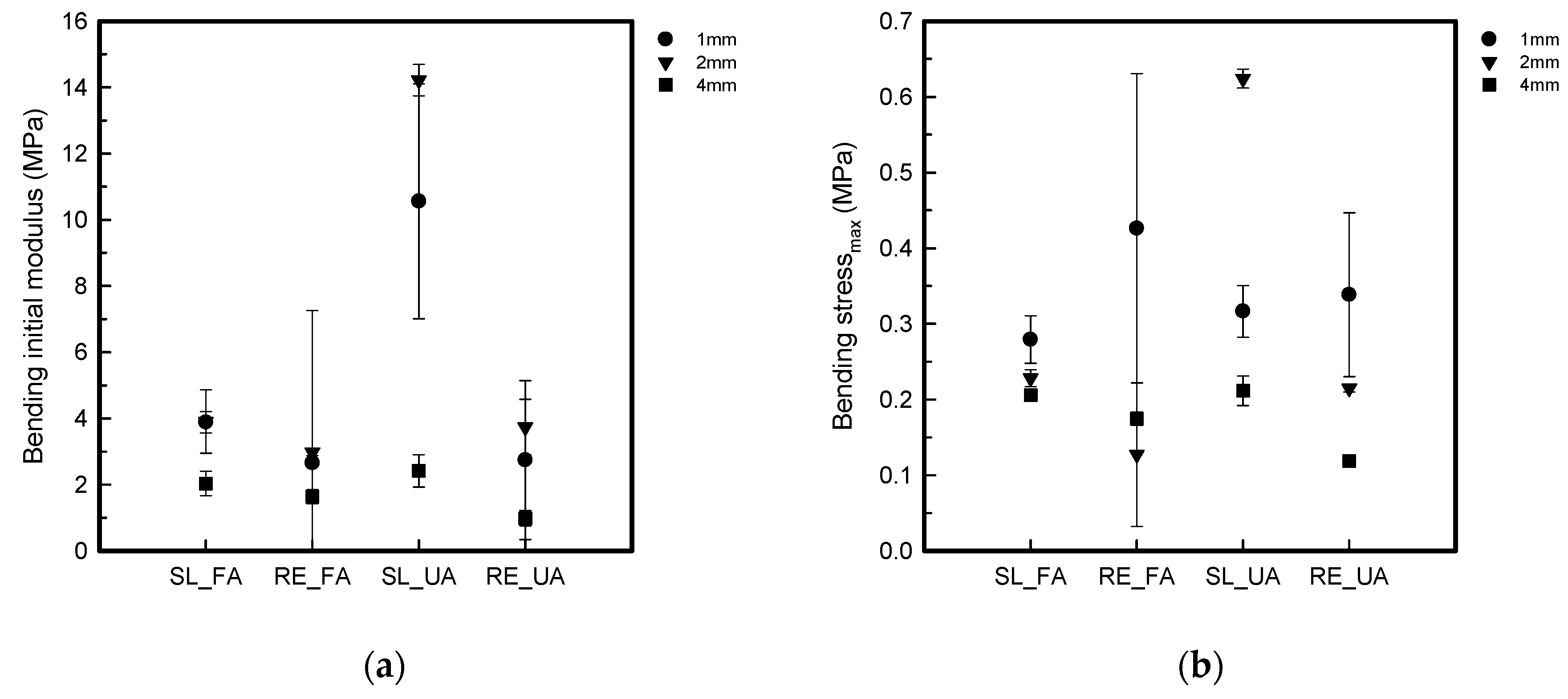
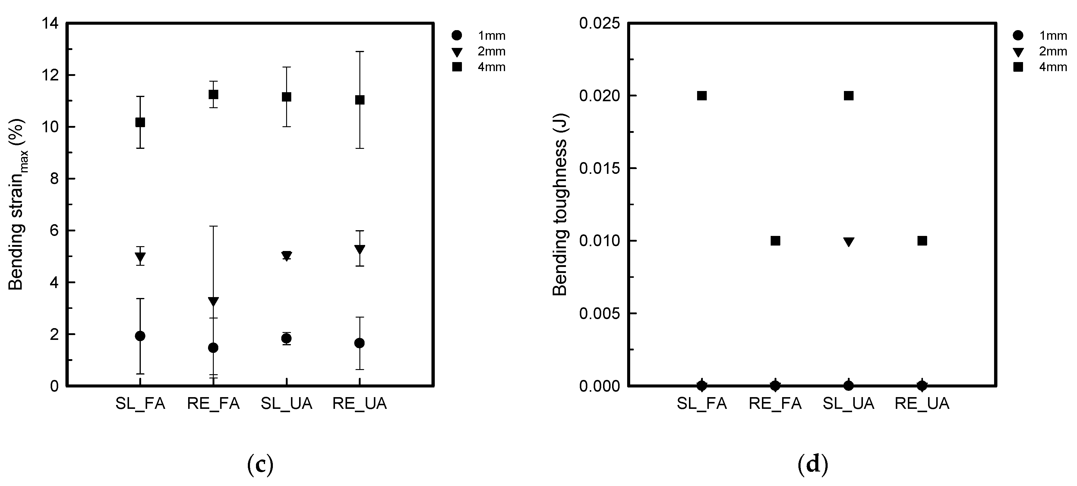
Bending Properties
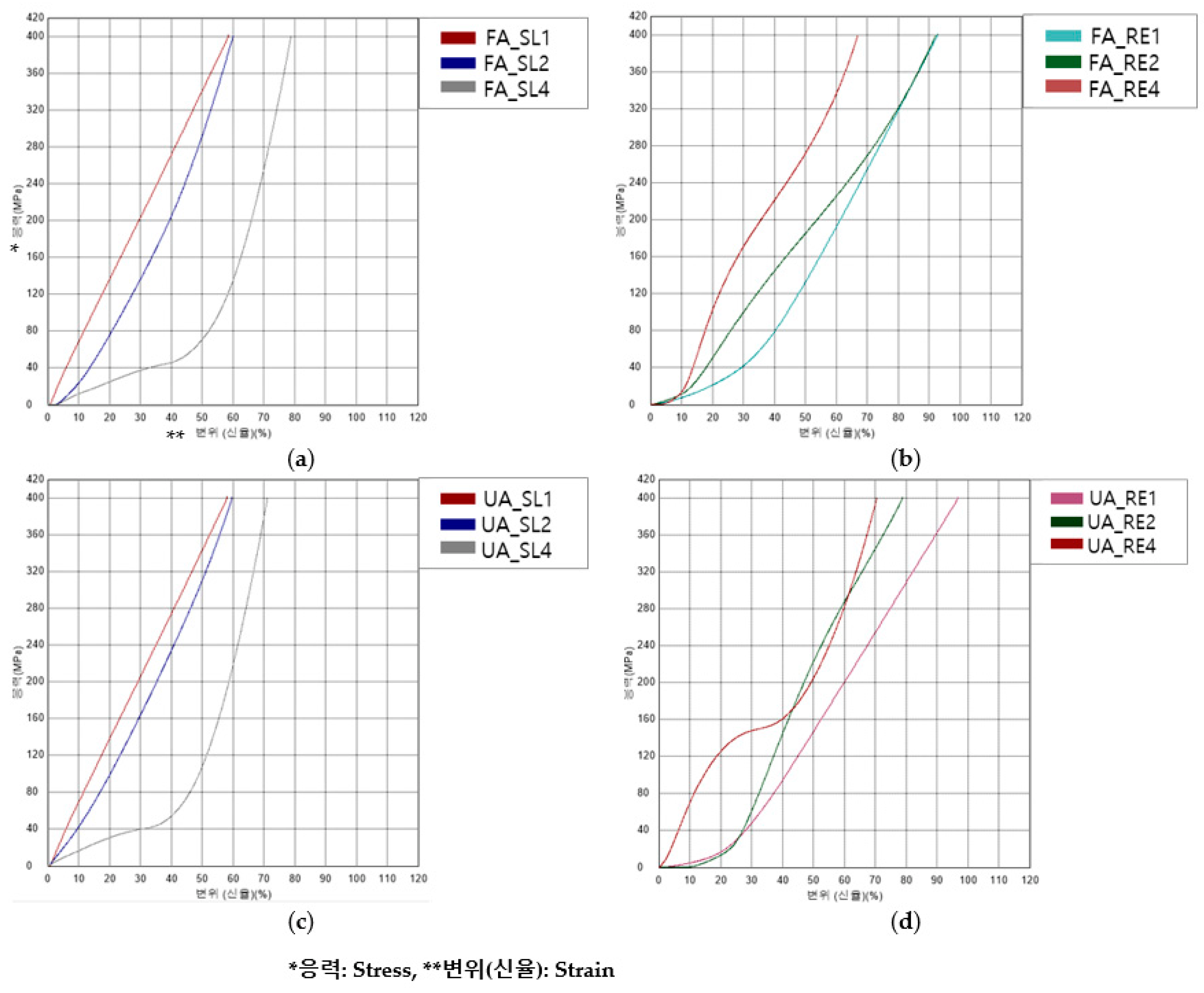
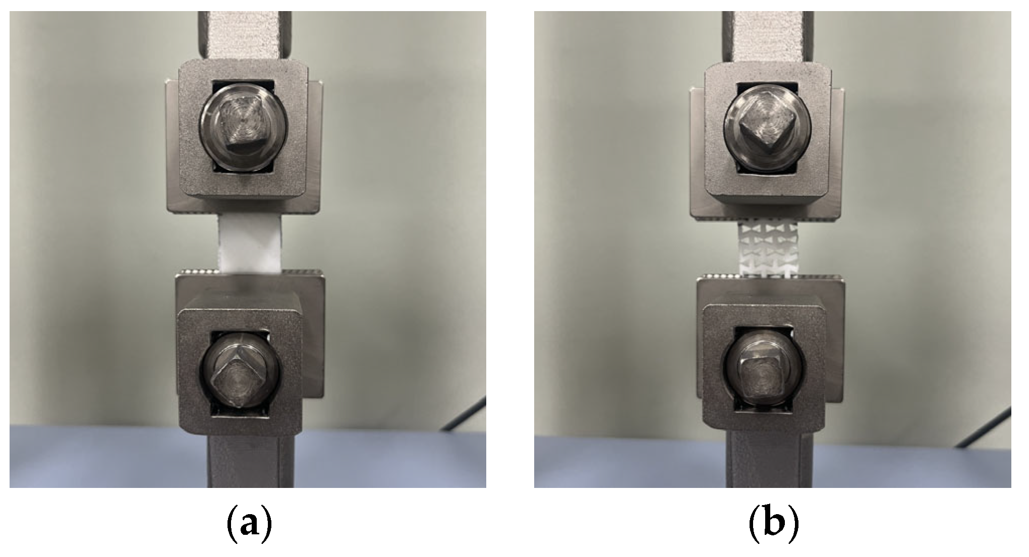
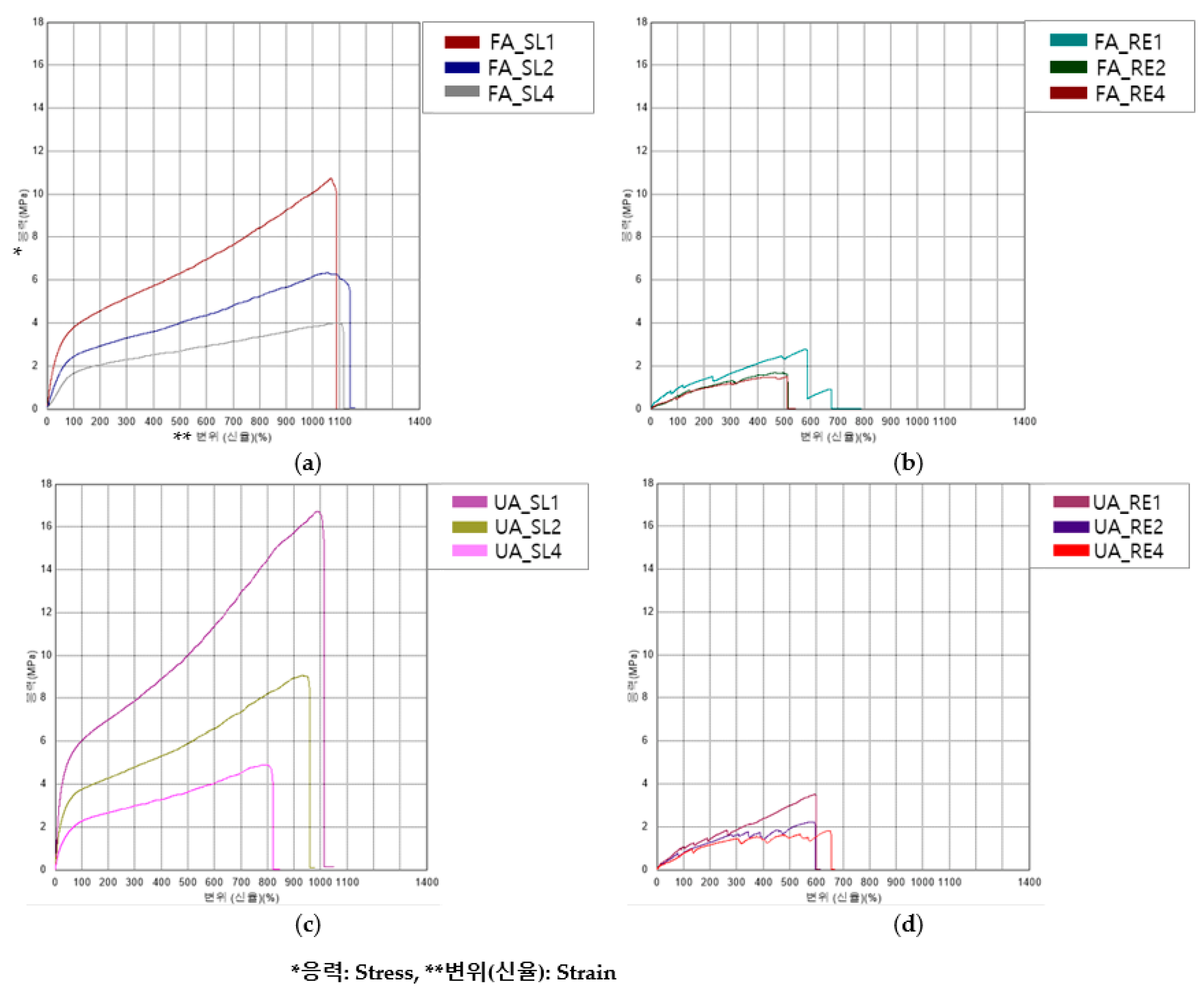
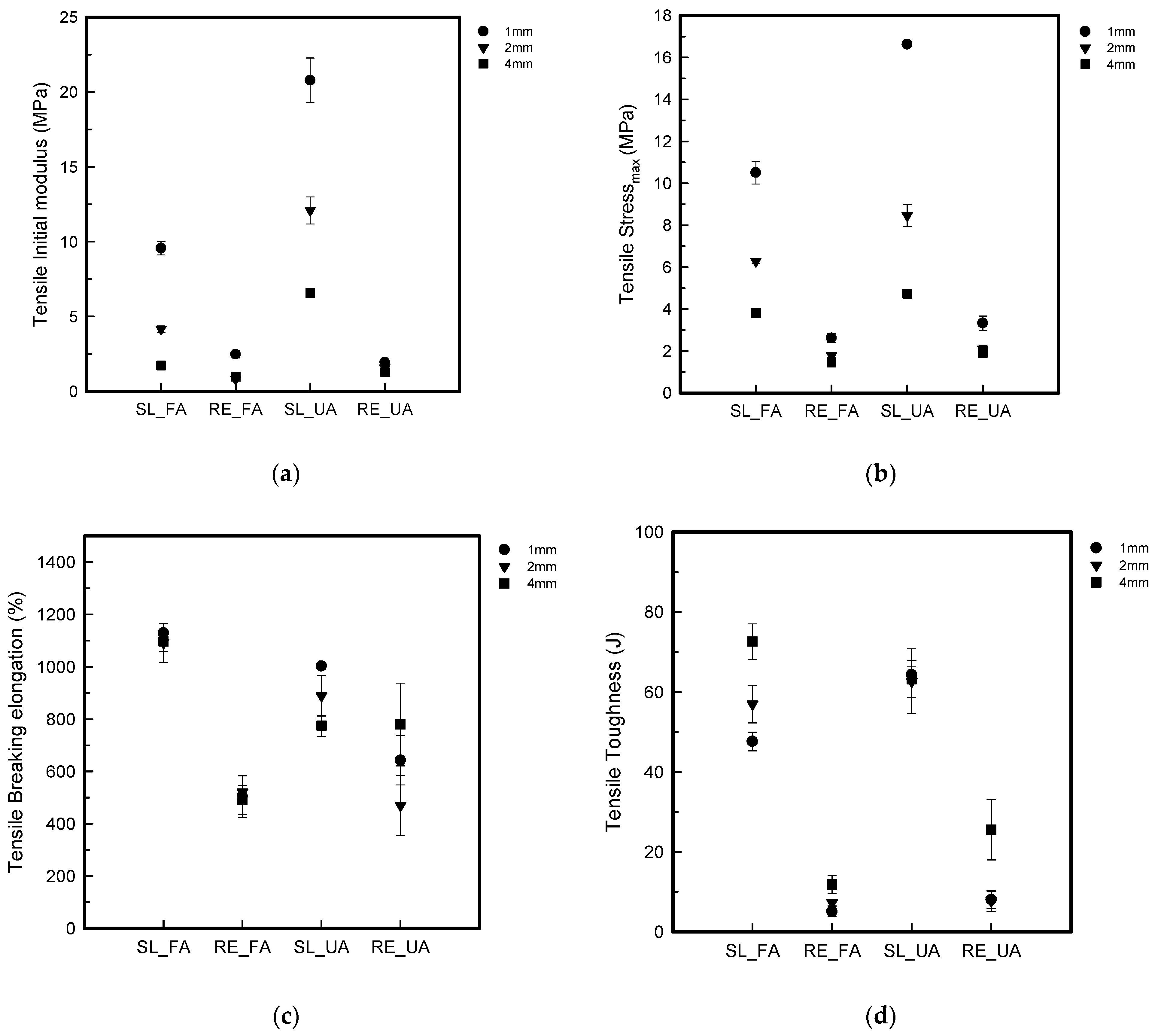
Tensile Properties
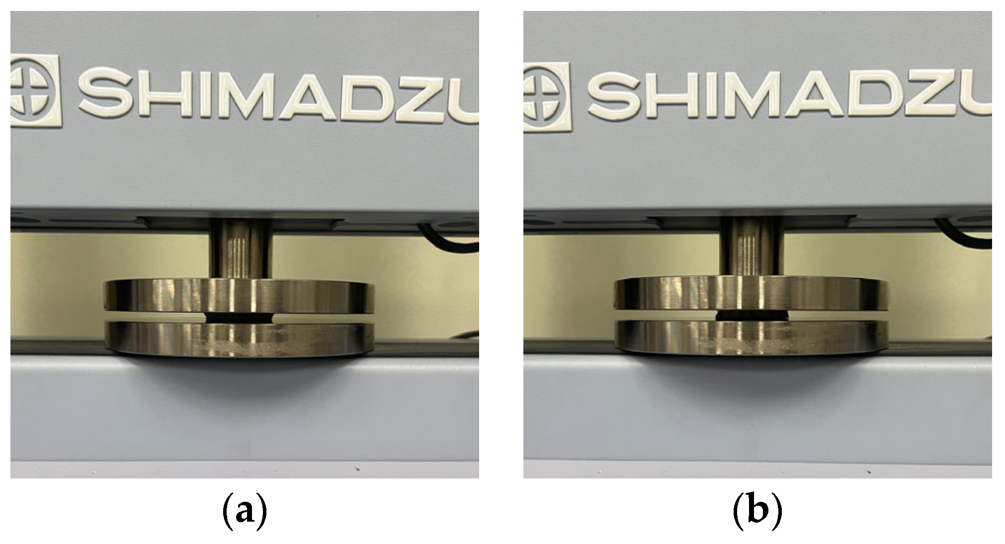
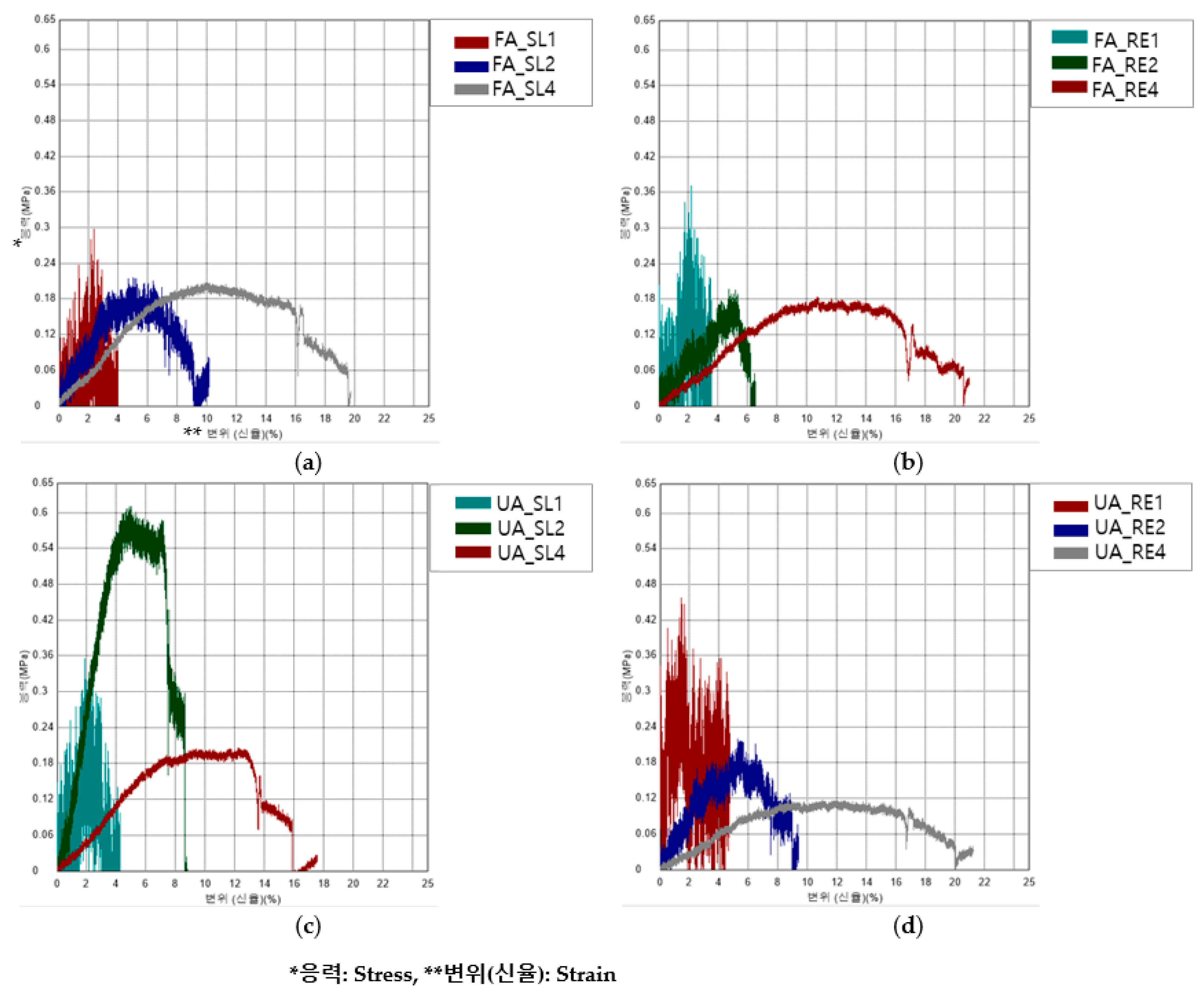
Compressive Property
3. Results and Discussion
3.1. Analysis of Sliced Images for Modeling of 3D-Printed Humanoid Robot Arm with Various Patterns and Thicknesses
3.2. Actual Printing Time and Weight of 3D-Printed Humanoid Robot Arm with Various Patterns and Thicknesses
3.3. Mechanical Properties of 3D-Printed Humanoid Robot Arm with Various Patterns and Thicknesses
3.3.1. Bending Properties
3.3.2. Tensile Properties
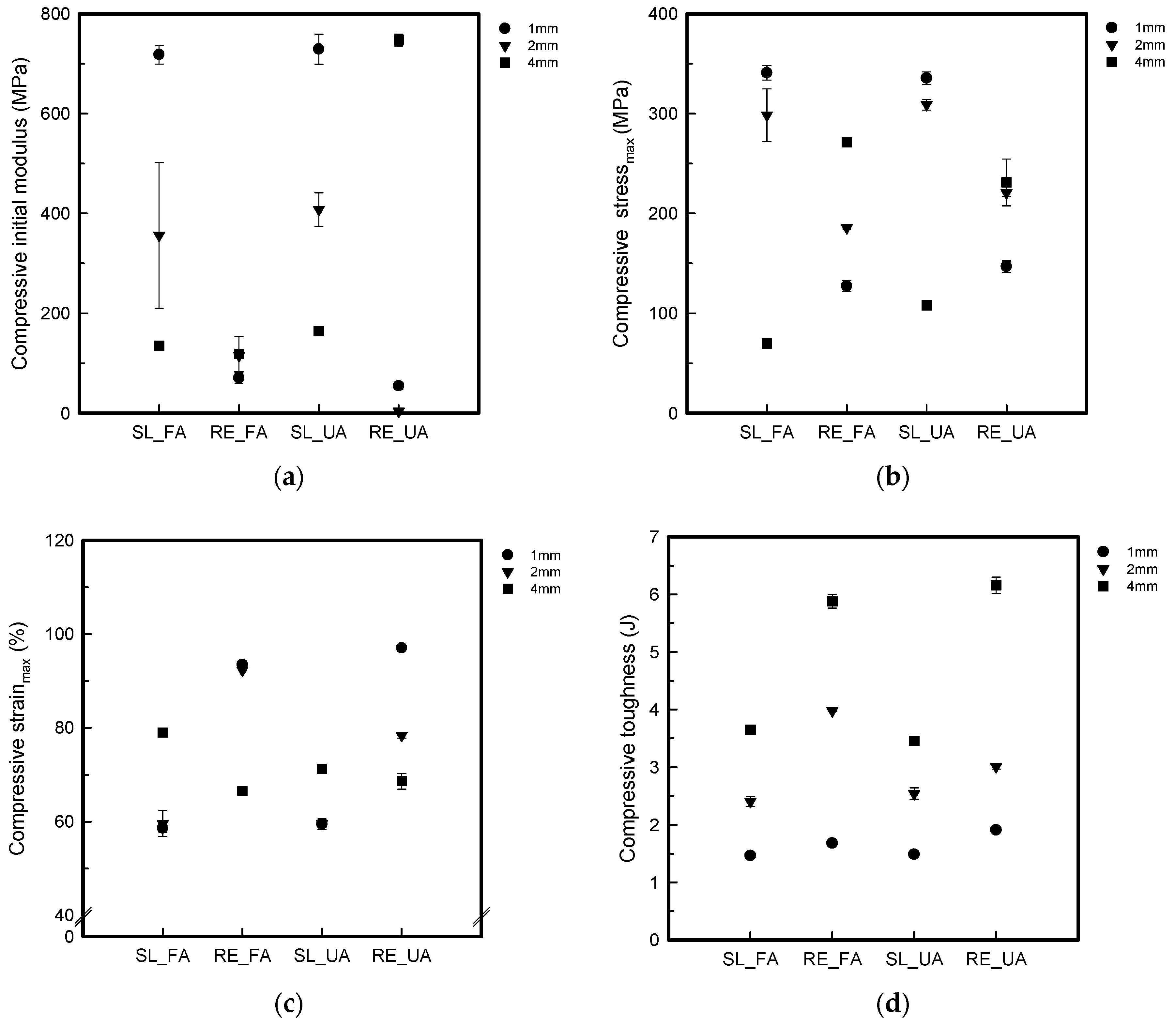
3.3.3. Compressive Property
4. Conclusions
Supplementary Materials
Author Contributions
Funding
Institutional Review Board Statement
Data Availability Statement
Conflicts of Interest
References
- Kang, B.B.; Choi, H.; Lee, H.; Cho, K.J. Exo-Glove Poly II: A Polymer-Based Soft Wearable Robot for the Hand with a Tendon-Driven Actuation System. Soft Robot. 2019, 6, 214–227. [Google Scholar] [CrossRef] [PubMed]
- Osawa, Y.; Kinbara, Y.; Kageoka, M.; Lida, K.; Kheddar, A. Soft robotic shell with active thermal display. Sci. Rep. 2021, 11, 20070. [Google Scholar] [CrossRef] [PubMed]
- Duncan, O.; Shepherd, T.; Moroney, C.; Foster, L.; Venkatraman, P.D.; Winwood, K.; Allen, T.; Alderson, A. Review of Auxetic Materials for Sports Applications: Expanding Options in Comfort and Protection. Sci. Rep. 2018, 8, 941. [Google Scholar] [CrossRef]
- Xue, Y.; Gao, P.; Zhou, L.; Han, F. An enhanced three-dimensional auxetic lattice structure with improved property. Materials 2019, 13, 1008. [Google Scholar] [CrossRef] [PubMed]
- Zhang, J.; Lu, G.; You, Z. Large deformation and energy absorption of additively manufactured auxetic materials and structures: A review. Composites 2020, 201, 108340. [Google Scholar] [CrossRef]
- Lakes, R.S. Negative-Poisson’s-Ratio Materials: Auxetic Solids. Ann. Rev. 2017, 47, 63–81. [Google Scholar] [CrossRef]
- Meeusen, L.; Candidori, S.; Micoli, L.L.; Guidi, G.; Stanković, T.; Graziosi, S. Auxetic structures used in kinesiology tapes can improve form-fitting and personalization. Sci. Rep. 2022, 12, 13509. [Google Scholar] [CrossRef] [PubMed]
- Novak, N.; Dubrovski, P.D.; Borovinšek, M.; Vesenjak, M.; Ren, Z. Deformation behavior of advanced textile composites with auxetic structure. Compos. Struct. 2020, 252, 112761. [Google Scholar] [CrossRef]
- Papadopoulou, A.; Laucks, J.; Tibbits, S. Auxetic materials in design and architecture. Nat. Rev. Mater. 2017, 2, 17078. [Google Scholar] [CrossRef]
- Jung, I.; Kim, H.; Lee, S. Characterizations of 3D printed re-entrant pattern/aramid knit composite prepared by various tilting angles. Fash. Text. 2021, 8, 44. [Google Scholar] [CrossRef]
- Bhullar, S.K. Three decades of auxetic polymers: A review. e-Polymers 2015, 15, 205–215. [Google Scholar] [CrossRef]
- Kim, H.; Lee, S. Mechanical properties of 3D printed re-entrant pattern with various hardness types of TPU filament manufactured through FDM 3D printing. Text. Sci. Eng. 2020, 57, 166–176. [Google Scholar]
- Kolken, H.M.A.; Zadpoor, A.A. Auxetic mechanical metamaterials. R. Soc. Chem. 2017, 7, 5111–5129. [Google Scholar] [CrossRef]
- Gu, L.; Xu, Q.; Du, Z. Analysis of tensile behavior of hyperelastic auxetic cellular materials with reentrant hexagonal cells. J. Text. Inst. 2020, 112, 173–186. [Google Scholar] [CrossRef]
- Yang, W.; Harrysson, O.; West, H.; Cormier, D. Mechanical properties of 3D re-entrant honeycomb auxetic structures realized via additive manufacturing. Int. J. Solids Struct. 2015, 69–70, 475–490. [Google Scholar] [CrossRef]
- Bhushan, J.; Grover, V. Additive Manufacturing: Current Concepts, Methods, and Applications in Oral Health Care. Biomanufacturing 2019, 103–122. [Google Scholar]
- Manaia, J.P.; Cerejo, F.; Duarte, J. Revolutionizing textile manufacturing: A comprehensive review on 3D and 4D printing technologies. Fash. Text. 2023, 10, 20. [Google Scholar] [CrossRef]
- Kristiawan, R.B.; Imaduddin, F.; Ariawan, D.; Ubaidillah; Arifin, Z. A review on the fused deposition modeling (FDM) 3D printing: Filament processing, materials, and printing parameters. Open Eng. 2020, 11, 639–649. [Google Scholar] [CrossRef]
- Kim, K.; Park, J.; Suh, J.; Kim, M.; Jeong, Y.; Park, I. 3D printing of multiaxial force sensors using carbon nanotube (CNT)/thermoplastic polyurethane (TPU) filaments. Sens. Actuators A Phys. 2017, 263, 493–500. [Google Scholar] [CrossRef]
- Frick, A.; Rochman, A. Characterization of TPU-elastomers by thermal analysis (DSC). Polym. Test. 2004, 23, 413–417. [Google Scholar] [CrossRef]
- Shin, E.J.; Jung, Y.S.; Choi, H.Y.; Lee, S. Synthesis and fabrication of bio based thermoplastic polyurethane filament for FDM 3D printing. J. Appl. Polym. Sci. 2022, 29, e52959. [Google Scholar] [CrossRef]
- Shin, E.J.; Park, Y.; Jung, Y.S.; Choi, H.Y.; Lee, S. Fabrication and characteristics of flexible thermoplastic polyurethane filament for fused deposition modeling three-dimensional printing. Polym. Eng. Sci. 2022, 62, 2947–2957. [Google Scholar] [CrossRef]
- Hou, S.; Li, T.; Jia, Z.; Wanga, L. Mechanical properties of sandwich composites with 3d-printed auxetic and non-auxetic lattice cores under low velocity impact. Mater. Des. 2018, 160, 1305–1321. [Google Scholar] [CrossRef]
- Lvov, V.A.; Senatov, F.S.; Korsunsky, A.M.; Salimon, A.I. Design and mechanical properties of 3d-printed auxetic honeycomb structure. Mater. Today Commun. 2020, 24, 101173. [Google Scholar] [CrossRef]
- Ho, L.C.; Yeah, H.S. A Characteristic Analysis on 3D printing materials for Textiles. Kor. Sci. Art For. 2016, 24, 343. [Google Scholar]
- Kabir, S.; Kim, H.; Lee, S. Characterization of 3D Printed Auxetic Sinusoidal Patterns/Nylon Composite Fabrics. Fibers Polym. 2020, 21, 1372–1381. [Google Scholar] [CrossRef]
- Jung, I.; Park, Y.E.; Choi, Y.R.; Kim, J.W.; Lee, S. A Study on the Motion Control of 3D Printed Fingers. Fash. Text. Rese. J. 2022, 24, 333–345. [Google Scholar] [CrossRef]
- Park, Y.; Lee, H.; Jung, I.; Lee, S. Characterization of 3D printed wrist brace with various tilting angles of re-entrant pattern using thermoplastic elastomer. J. Korean Soc. Cloth. Text. 2022, 46, 1074–1087. [Google Scholar] [CrossRef]
- Li, X. Human–robot interaction based on gesture and movement recognition. Signal Process. Image Commun. 2020, 81, 115686. [Google Scholar] [CrossRef]
- Ohta, P.; Valle, L.; King, J.; Low, K.; Yi, J.; Atkeson, C.G.; Park, Y.-L. Design of a lightweight soft robotic arm using pneumatic artificial muscles and inflatable sleeves. Soft Robot. 2018, 5, 119–227. [Google Scholar] [CrossRef]
- Jung, I.; Lee, S. Compressive Properties of 3D Printed TPU Samples with Various Infill Conditions. J. Korean Soc. Cloth. Text. 2022, 46, 481–493. [Google Scholar]
- KS M ISO 14125; Standard Test Method for Fibre-Reinforced Plastic Composites—Determination of Flexural Properties. Korean standard: Gwacheon-si, Gyeonggi-do, Republic of Korea, 2022. Available online: https://standard.go.kr/KSCI.
- KS K 0520; Standard Test Method for Textiles—Tensile Properties of Fabrics—Determination of Maximum Force and Elongation at Maximum Force Using the Grab Method. Korean standard: Seoul, Republic of Korea, 2021. Available online: https://standard.go.kr/KSCI.
- KS M ISO 604; Standard Test Method for Plastics—Determination of Compressive Properties. Korean standard: Gwacheon-si, Gyeonggi-do, Republic of Korea, 2023. Available online: https://standard.go.kr/KSCI.
- Babu, N.V.; Venkateshwaran, N.; Rajini, N.; Ismail, S.O.; Mohammad, F.; Al-Lohedan, H.A.; Siengchin, S. Influence of slicing parameters on surface quality and mechanical properties of 3D-printed CF/PLA composites fabricated by FDM technique. Mater. Tech. 2021, 37, 1008–1025. [Google Scholar] [CrossRef]
- Kim, H.; Kabir, S.; Lee, S. Mechanical properties of 3D printed re-entrant pattern/neoprene composite textile by pattern tilting angle of pattern. J. Korean Soc. Cloth. Text. 2021, 45, 106–122. [Google Scholar] [CrossRef]
- Saxena, K.K.; Das, R.; Calius, E.P. Three Decades of Auxetics Research—Materials with Negative Poisson’s Ratio: A Review. Adv. Eng. Mat. 2016, 18, 1847–1870. [Google Scholar] [CrossRef]
- Wang, Z.; Hu, H. Auxetic materials and their potential applications in textiles. Text. Rese. J. 2014, 84, 1600–1611. [Google Scholar] [CrossRef]
- Saeedvand, S.; Jafari, M.; Aghdasi, H.S.; Baltes, J. A comprehensive survey on humanoid robot development. Know. Eng. Rev. 2019, 34, e20. [Google Scholar] [CrossRef]
- Kabir, S.; Lee, S. Study of shape memory and tensile property of 3D printed sinusoidal sample/nylon composite focused on various thicknesses and shape memory cycles. Polymers 2020, 12, 1600. [Google Scholar] [CrossRef]
- Chapa, A.; Cuan-Urquizo, E.; Urbina-Coronado, P.D.; Roman-Flores, A. Experimental characterization of the mechanical properties of 3D printed TPU auxetic cellular materials under cyclic compressive loadings. Rapi. Prot. J. 2023, 29, 1355–2546. [Google Scholar] [CrossRef]


| Arm Part | Pattern Image | Thickness (mm) | Size (mm3) | Sample Code | |||
|---|---|---|---|---|---|---|---|
| Robot | Modeling Image | Forearm (FA) | Upper Arm (UA) | ||||
| Forearm (FA) | 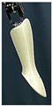 |  | Solid (SL)  | 1 | 165.0 × 130.0 × 1.0 | FA_SL1 | UA_SL1 |
| 2 | 165.0 × 130.0 × 2.0 | FA_SL2 | UA_SL2 | ||||
| 4 | 165.0 × 130.0 × 4.0 | FA_SL4 | UA_SL4 | ||||
| Upper arm (UA) | 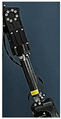 | 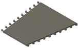 | Re-entrant (RE)  | 1 | 190.0 × 155.0 × 1.0 | FA_RE1 | UA_RE1 |
| 2 | 190.0 × 155.0 × 2.0 | FA_RE2 | UA_RE2 | ||||
| 4 | 190.0 × 155.0 × 4.0 | FA_RE4 | UA_RE4 | ||||
| Sample Code | Slicing | Sample Code | Slicing | ||
|---|---|---|---|---|---|
| Top | Front | Top | Front | ||
| FA_SL1 | 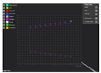 | 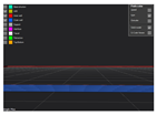 | UA_SL1 |  |  |
| FA_SL2 |  | 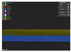 | UA _SL2 | 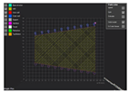 | 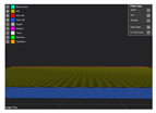 |
| FA_SL4 | 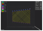 |  | UA _SL4 | 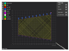 | 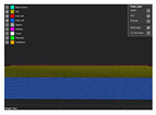 |
| FA_RE1 | 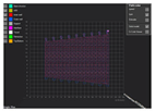 | 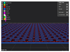 | UA _RE1 |  | 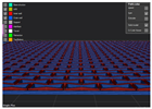 |
| FA_RE2 | 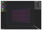 | 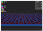 | UA _RE2 | 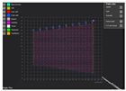 |  |
| FA_RE4 |  | 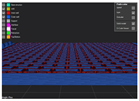 | UA _RE4 |  |  |
| Sample Code | Sample Image | Sample Code | Sample Image | Sample Code | Sample Image | Sample Code | Sample Image |
|---|---|---|---|---|---|---|---|
| FA_SL1 |  | FA_RE1 | 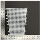 | UA_SL1 |  | UA_RE1 | 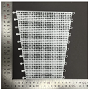 |
| FA_SL2 | 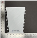 | FA_RE2 | 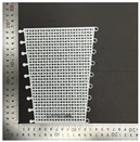 | UA_SL2 |  | UA_RE2 | 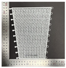 |
| FA_SL4 |  | FA_RE4 |  | UA_SL4 |  | UA_RE4 | 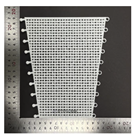 |
Disclaimer/Publisher’s Note: The statements, opinions and data contained in all publications are solely those of the individual author(s) and contributor(s) and not of MDPI and/or the editor(s). MDPI and/or the editor(s) disclaim responsibility for any injury to people or property resulting from any ideas, methods, instructions or products referred to in the content. |
© 2024 by the authors. Licensee MDPI, Basel, Switzerland. This article is an open access article distributed under the terms and conditions of the Creative Commons Attribution (CC BY) license (https://creativecommons.org/licenses/by/4.0/).
Share and Cite
Chowdhury, D.; Park, Y.-E.; Jung, I.; Lee, S. Characterization of Exterior Parts for 3D-Printed Humanoid Robot Arm with Various Patterns and Thicknesses. Polymers 2024, 16, 988. https://doi.org/10.3390/polym16070988
Chowdhury D, Park Y-E, Jung I, Lee S. Characterization of Exterior Parts for 3D-Printed Humanoid Robot Arm with Various Patterns and Thicknesses. Polymers. 2024; 16(7):988. https://doi.org/10.3390/polym16070988
Chicago/Turabian StyleChowdhury, Dikshita, Ye-Eun Park, Imjoo Jung, and Sunhee Lee. 2024. "Characterization of Exterior Parts for 3D-Printed Humanoid Robot Arm with Various Patterns and Thicknesses" Polymers 16, no. 7: 988. https://doi.org/10.3390/polym16070988
APA StyleChowdhury, D., Park, Y.-E., Jung, I., & Lee, S. (2024). Characterization of Exterior Parts for 3D-Printed Humanoid Robot Arm with Various Patterns and Thicknesses. Polymers, 16(7), 988. https://doi.org/10.3390/polym16070988