


Mechanical Properties and Performance of 3D-Printed Acrylonitrile Butadiene Styrene Reinforced with Carbon, Glass and Basalt Short Fibers


Abstract
1. Introduction
2. Materials and Methods
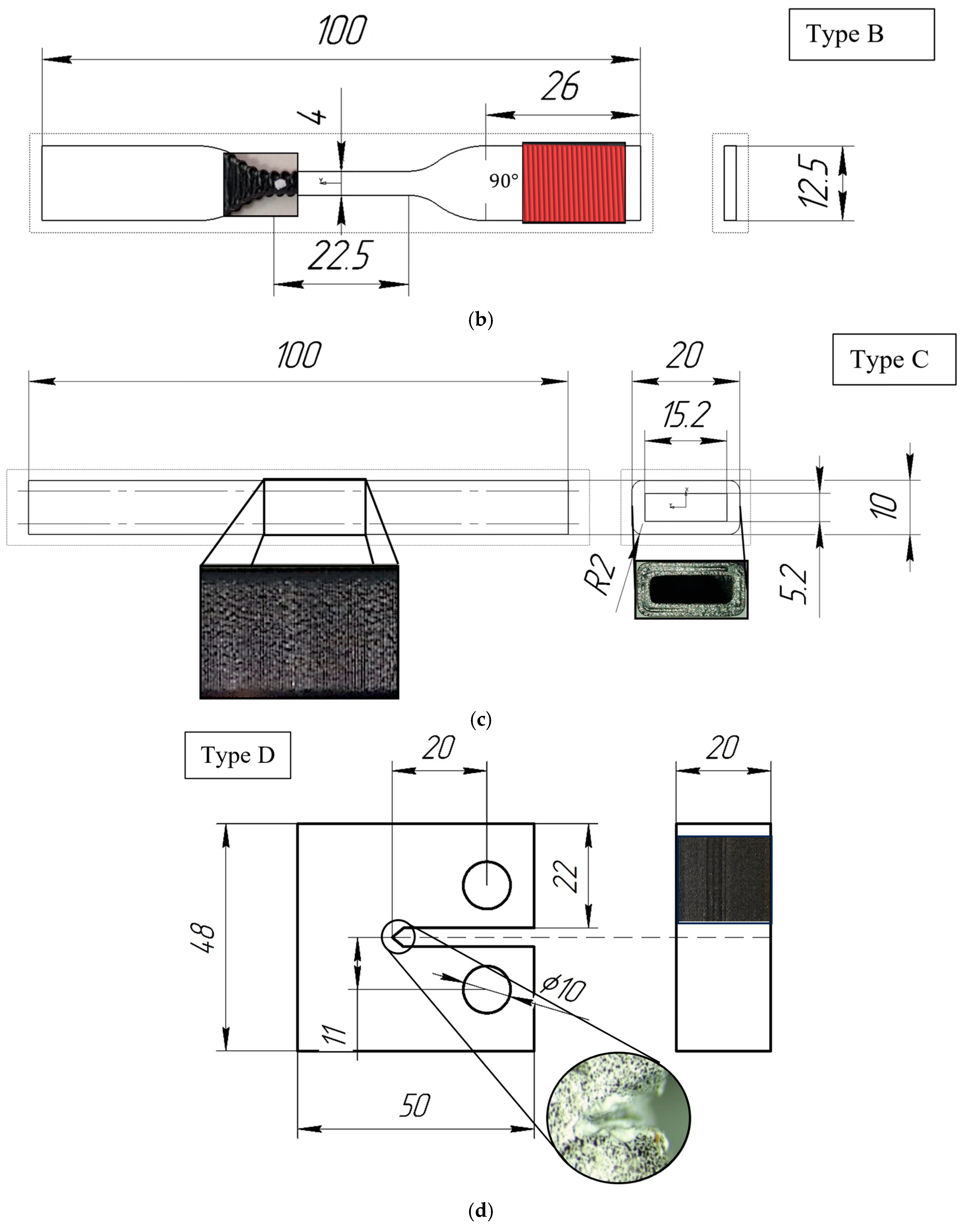
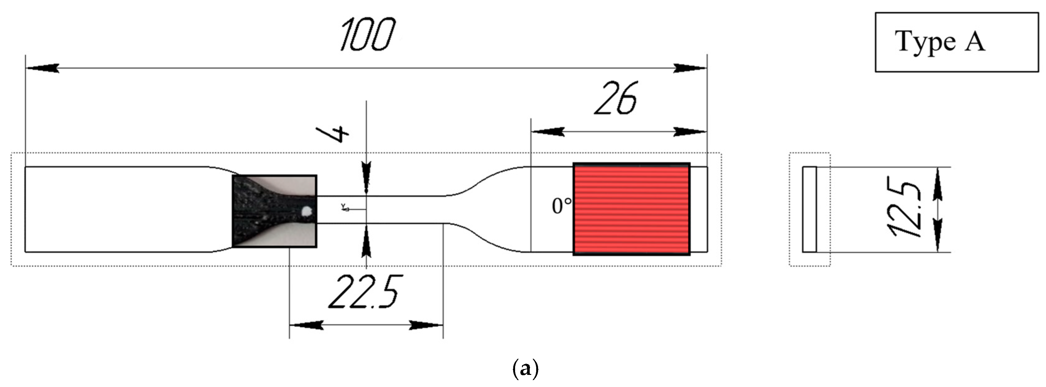
2.1. Manufacturing of Samples
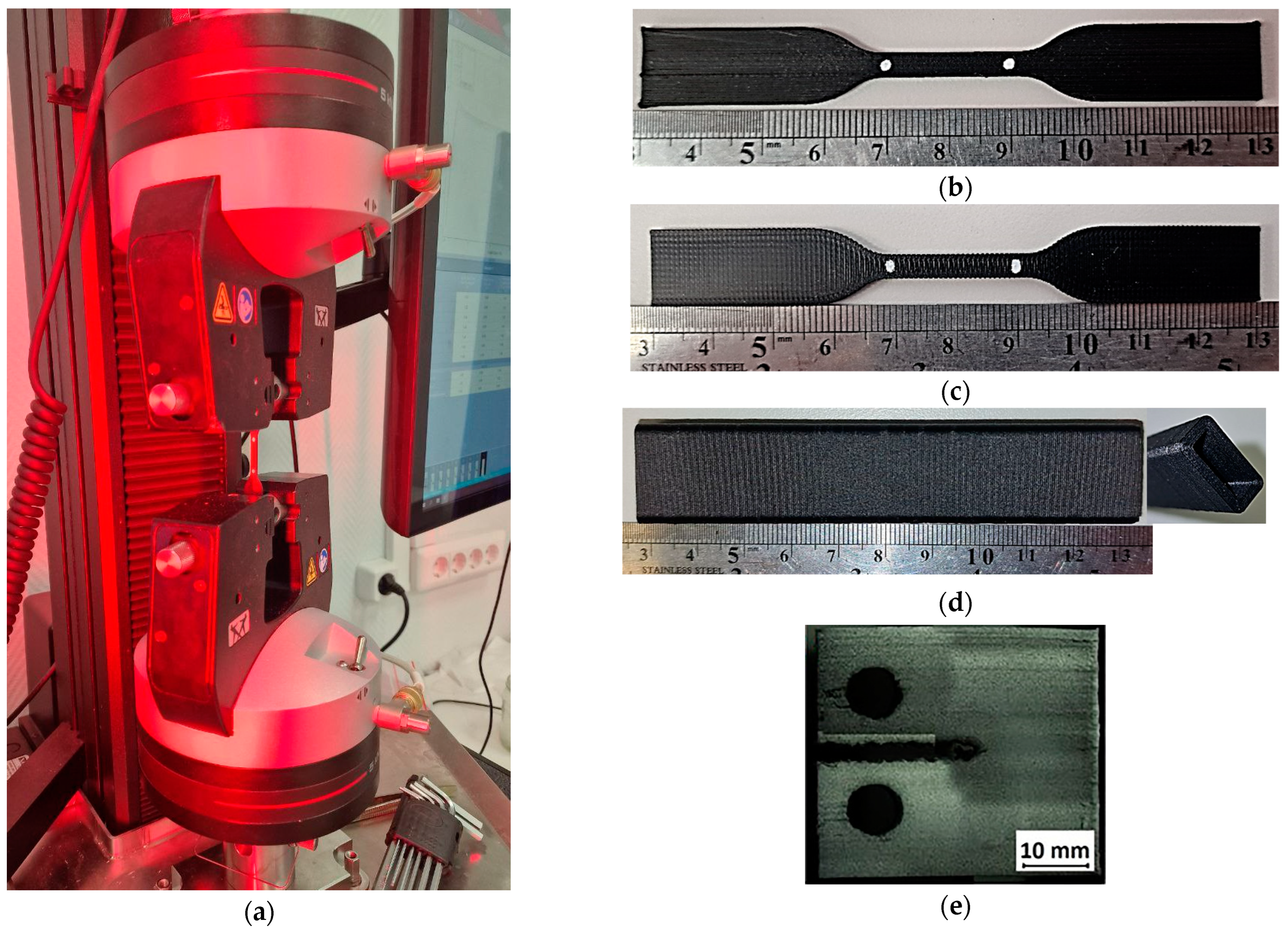
2.2. Mechanical Testing
2.3. Microtomography
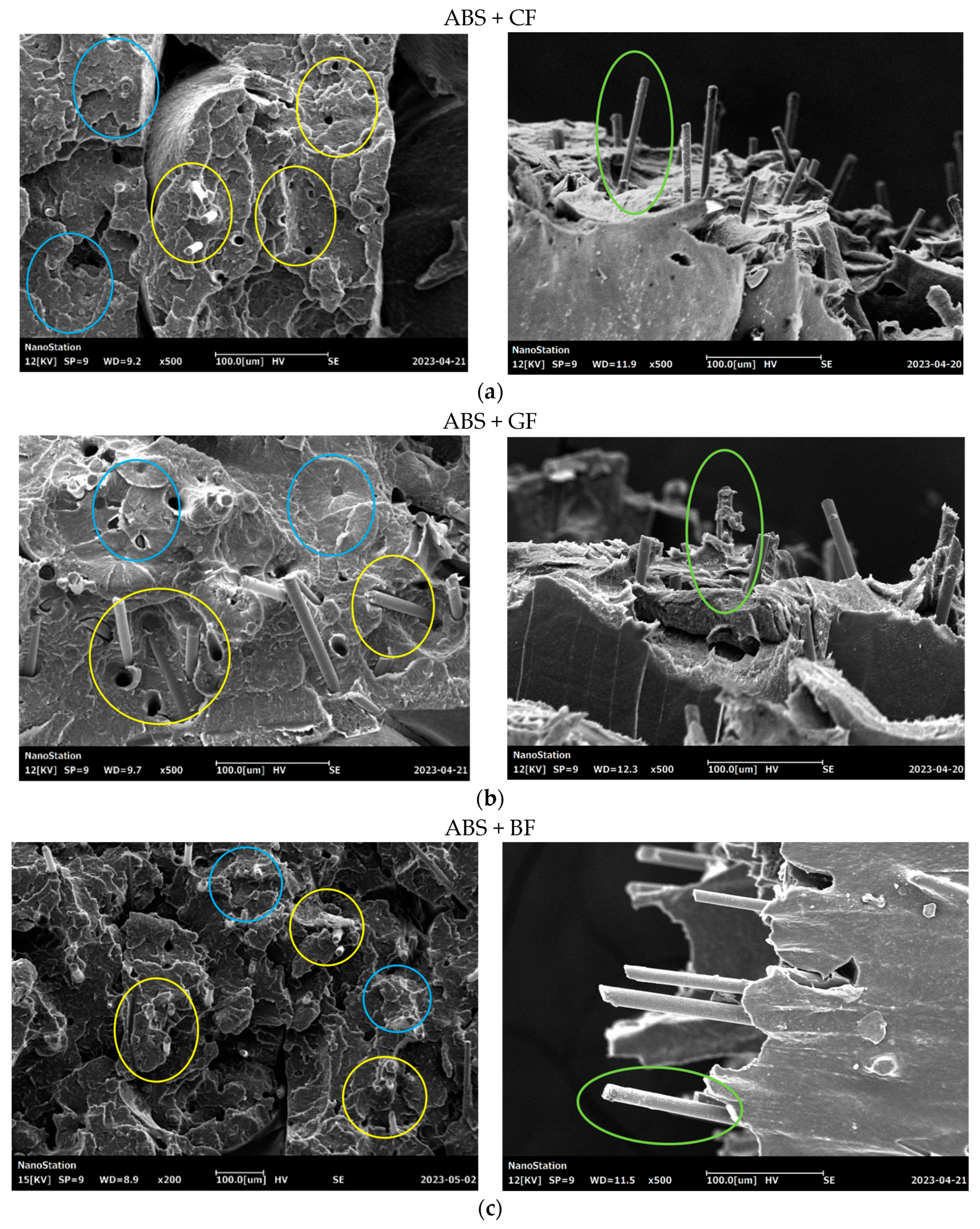
2.4. Scanning Electronic Microscopy
3. Results
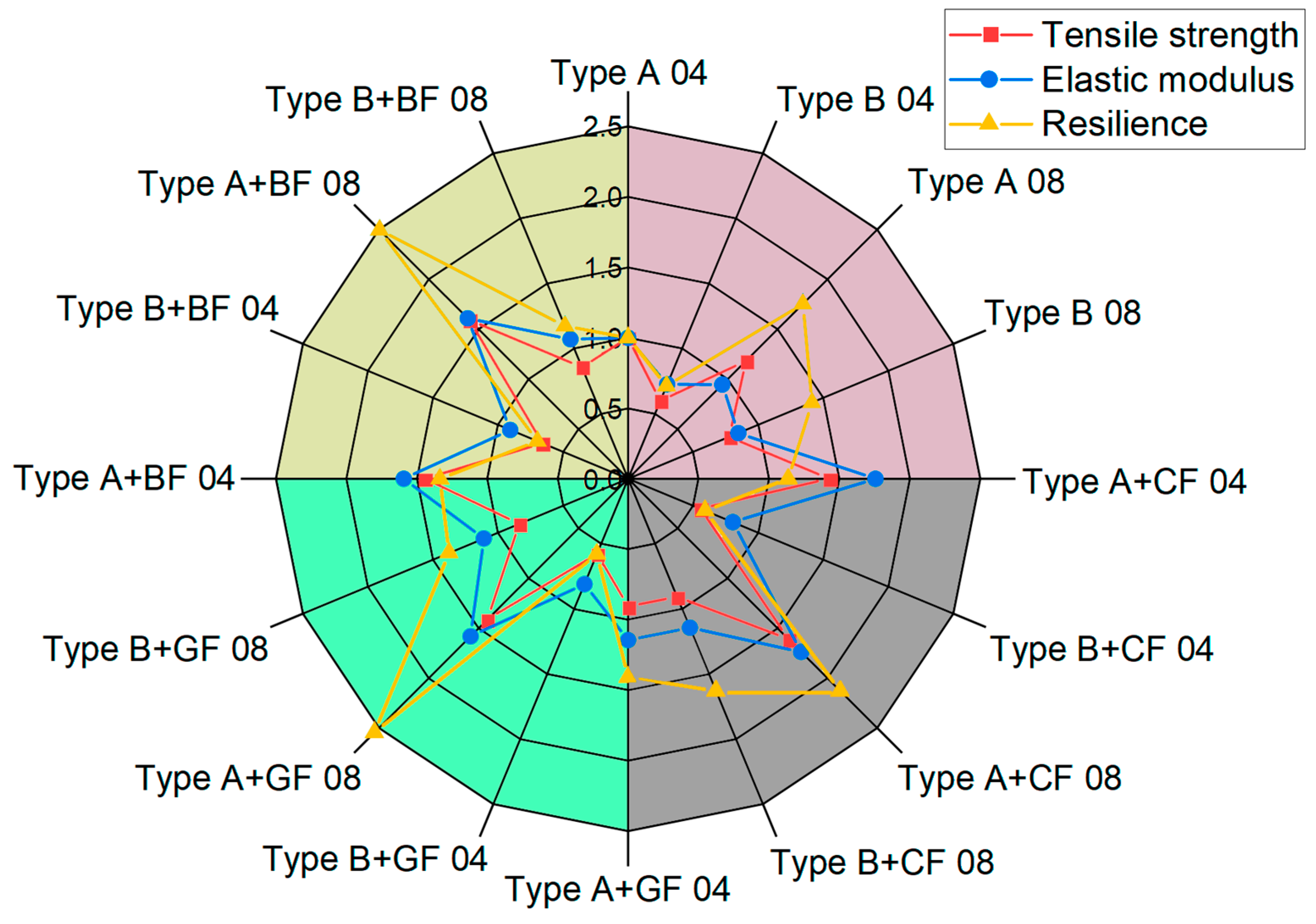
3.1. Stiffness and Strength
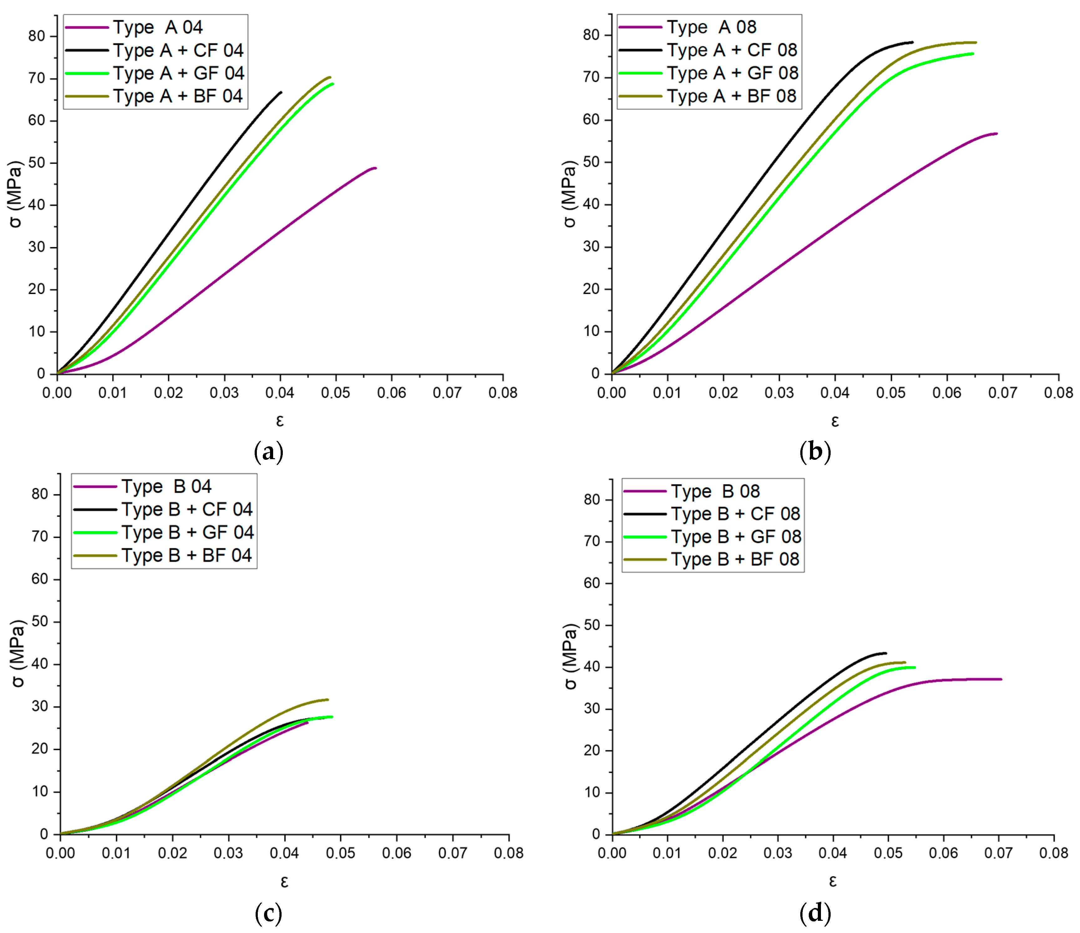
3.1.1. Tensile Properties
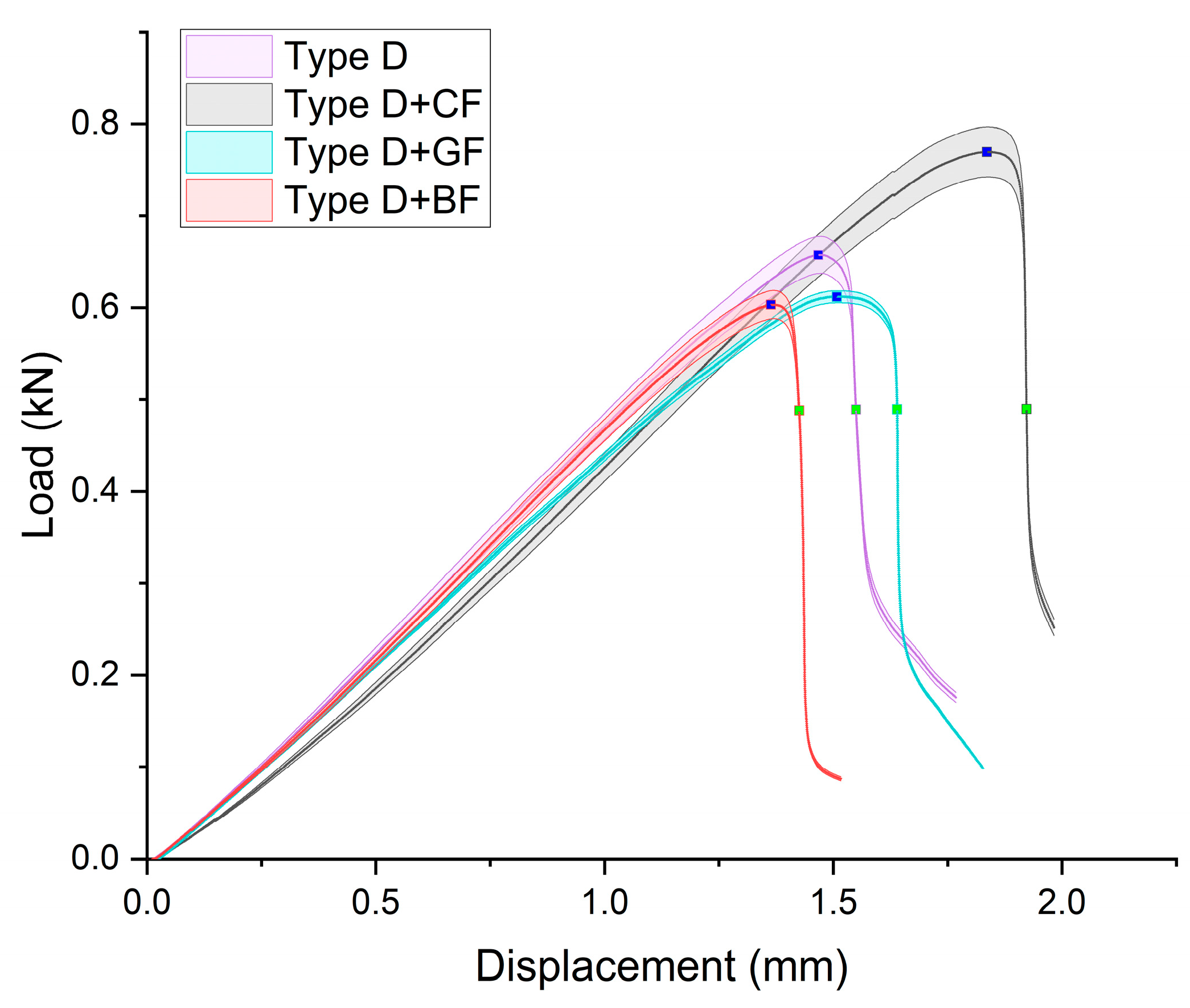
3.1.2. Fracture Toughness
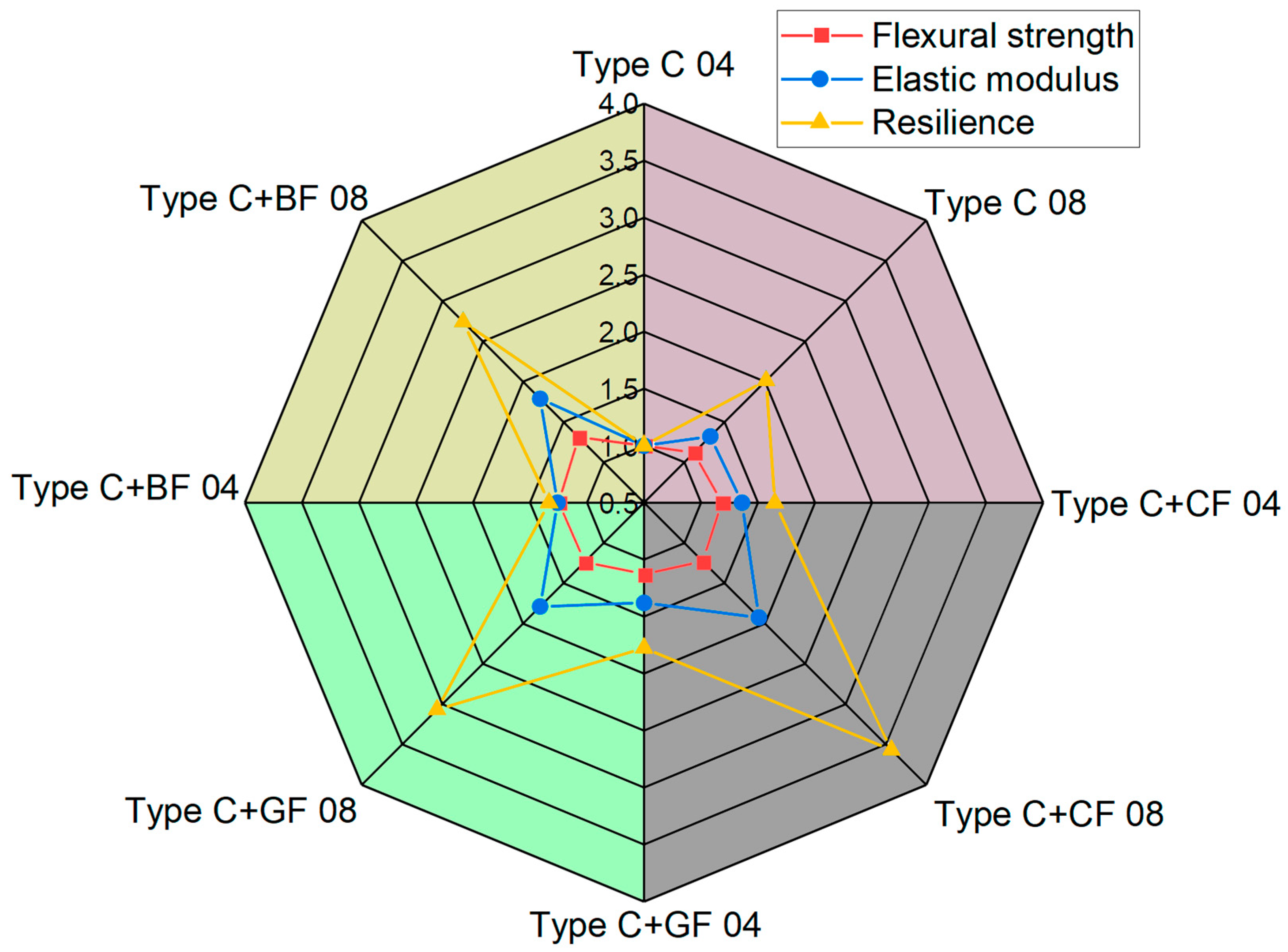
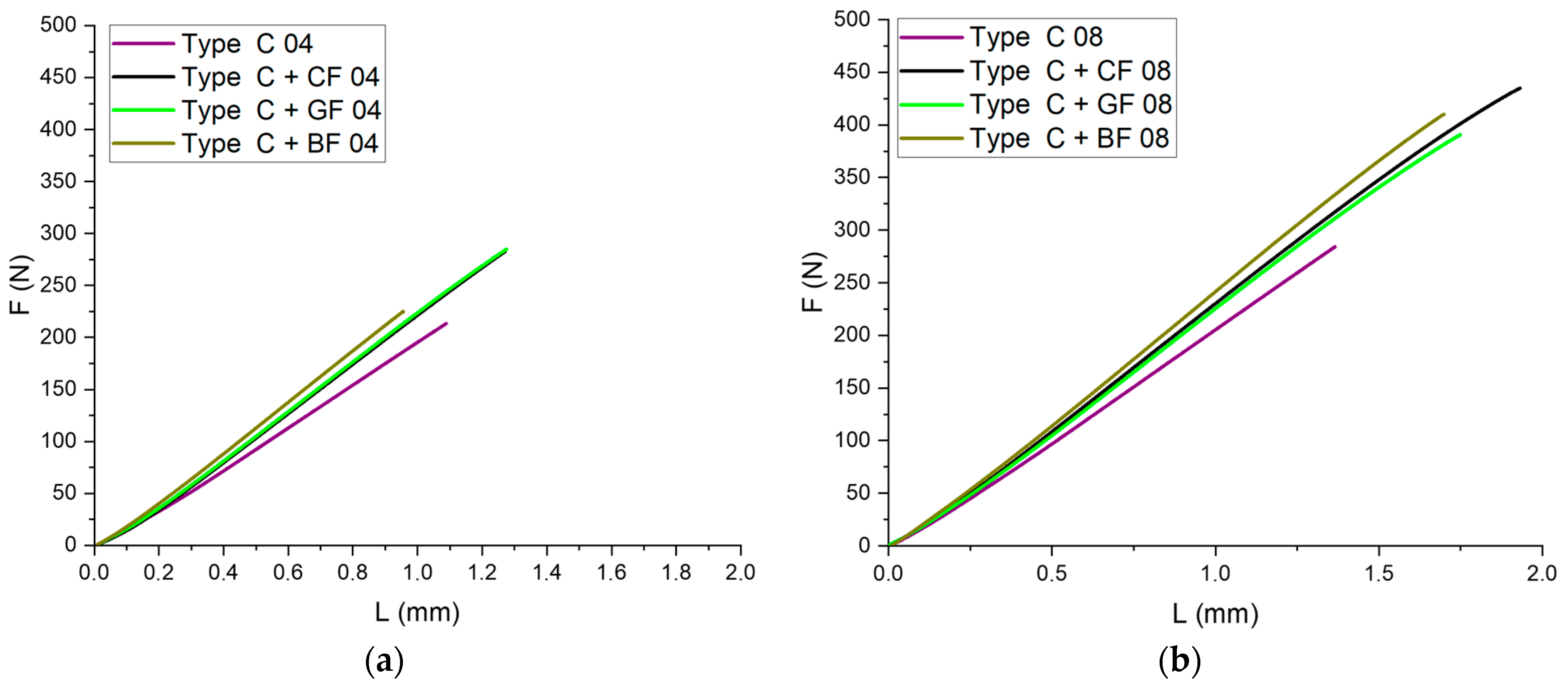
3.2. Bending Tests
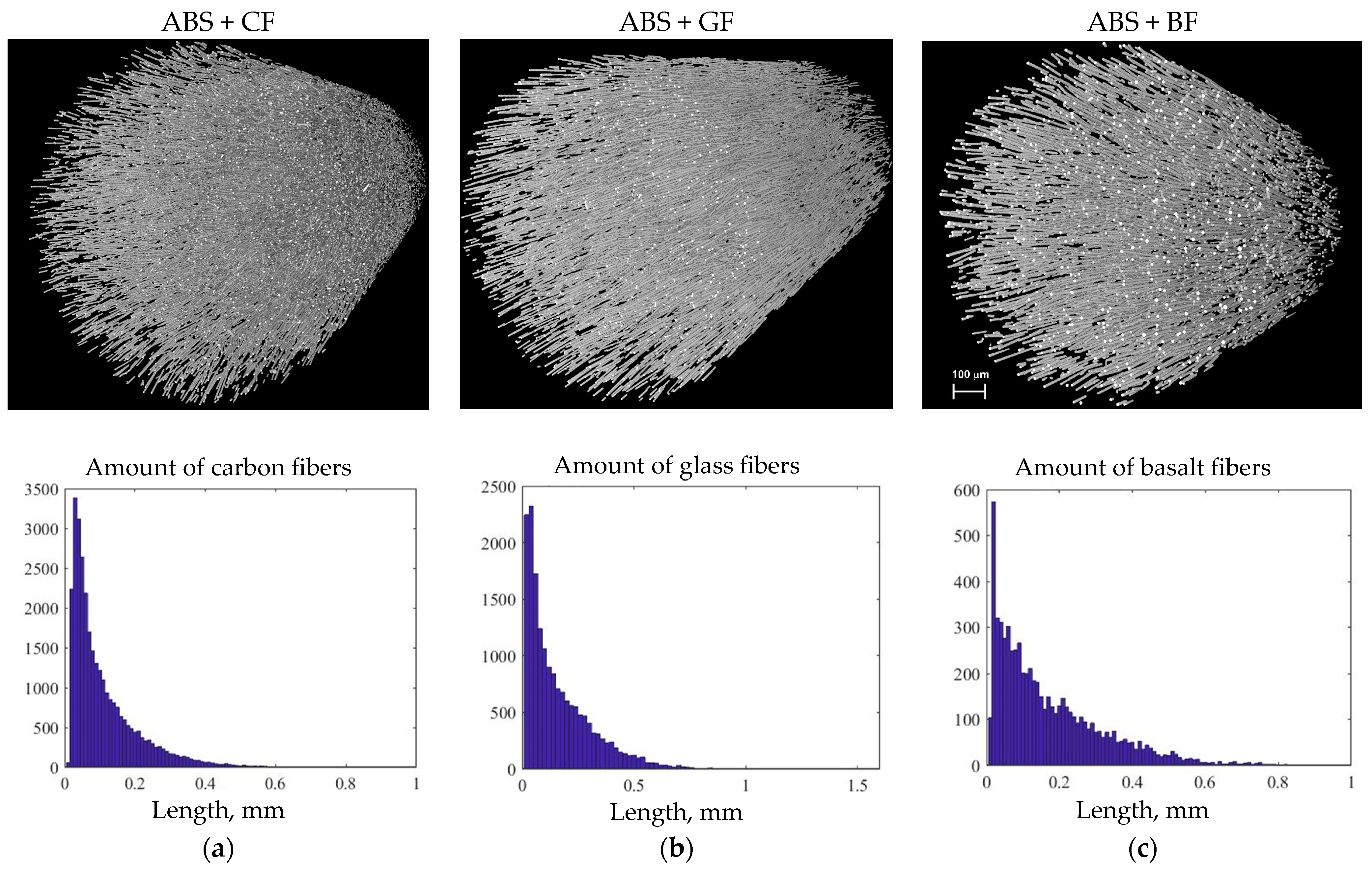
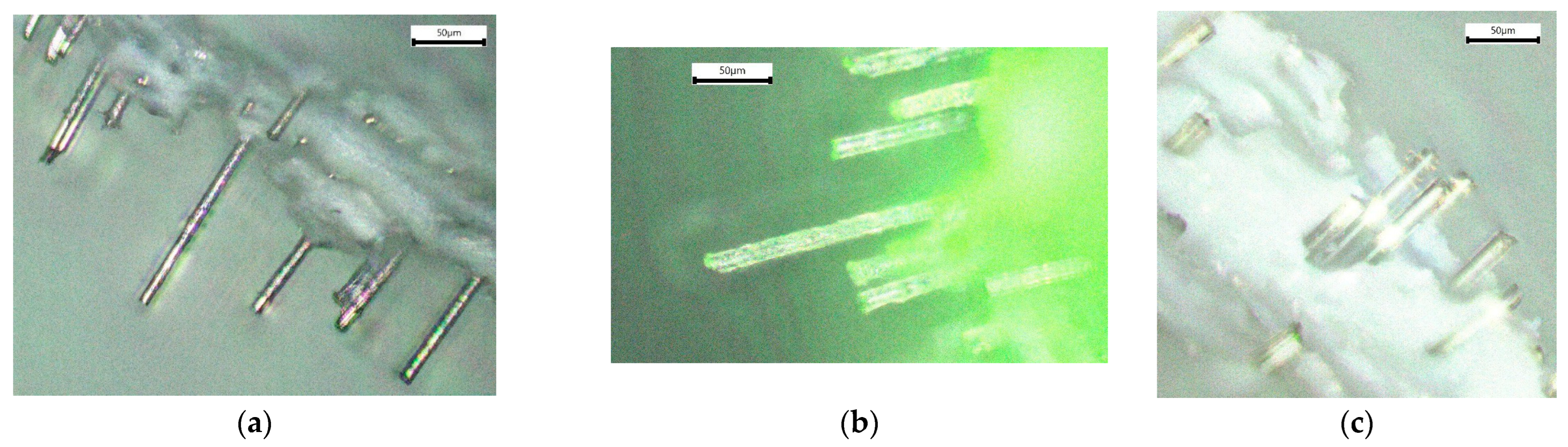
3.3. Analysis of Microstructure
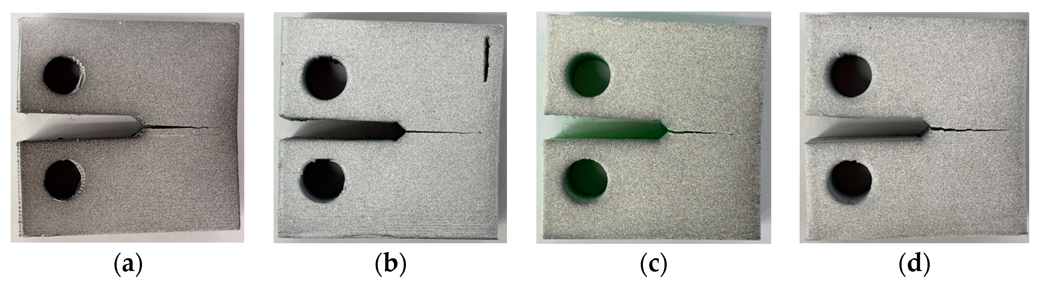
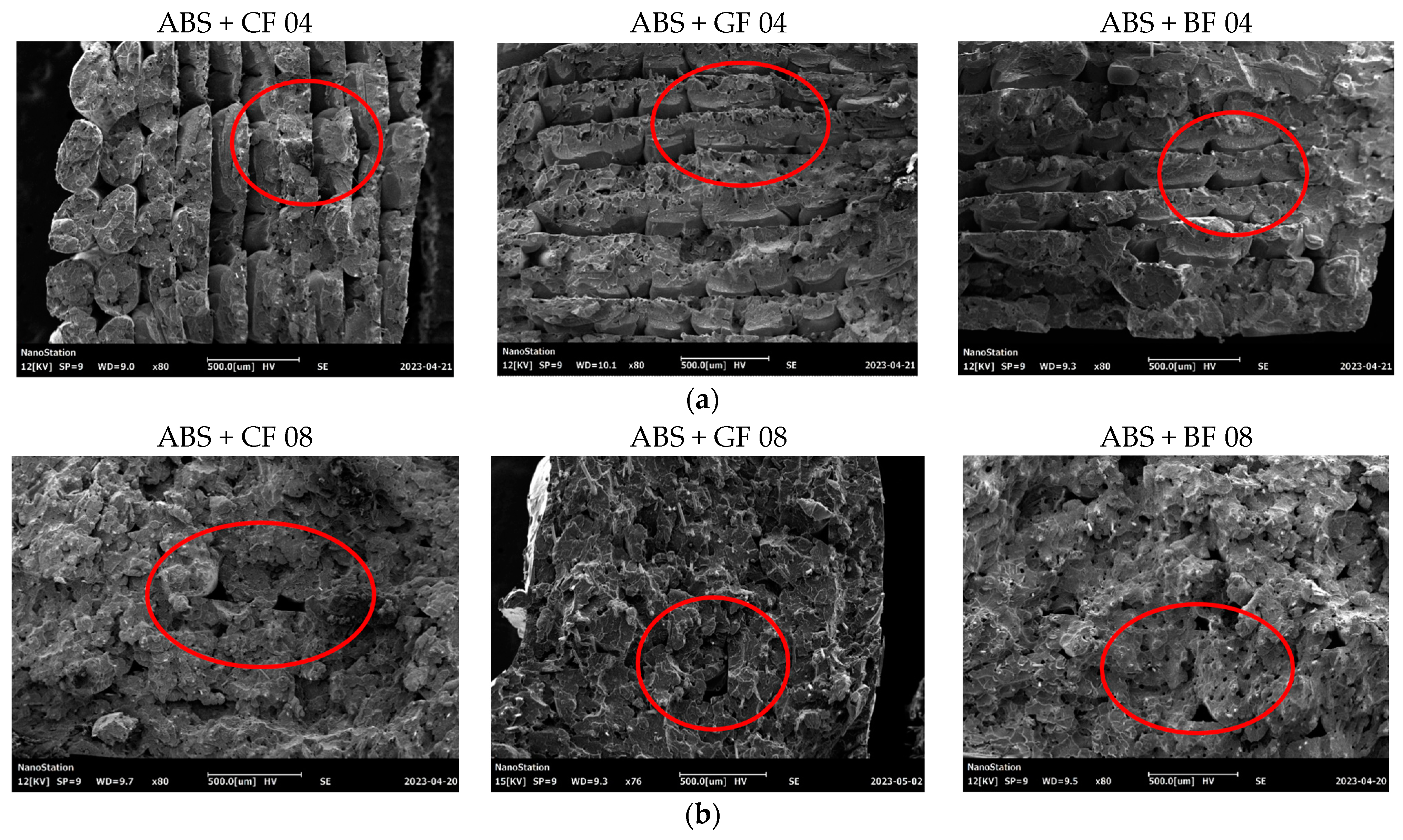
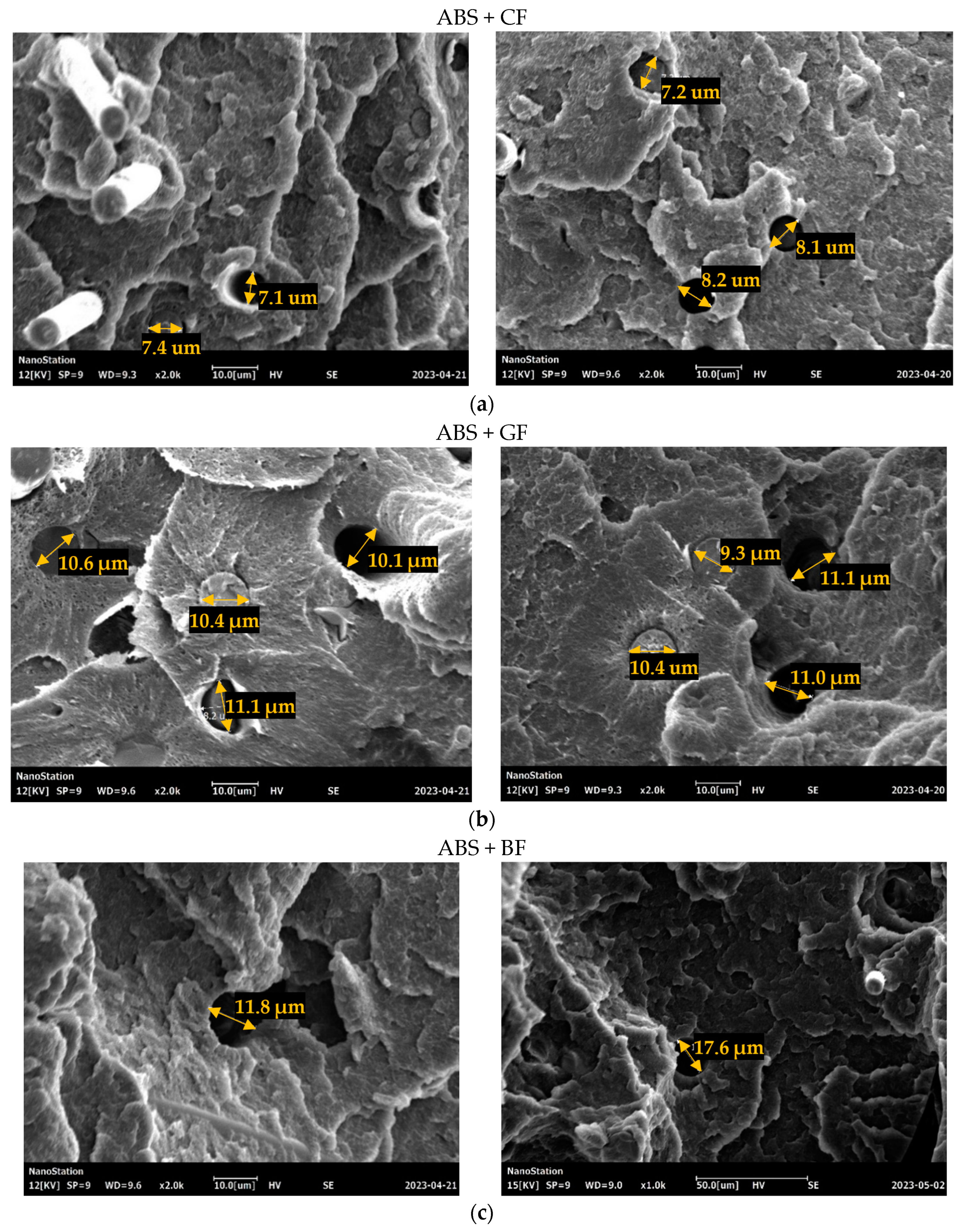
3.4. Analysis of Fracture Surface
4. Discussion
5. Conclusions
Author Contributions
Funding
Institutional Review Board Statement
Data Availability Statement
Conflicts of Interest
References
- Abdellah, M.; Fathi, H.; Abdelhaleem, A.; Dewidar, M. Mechanical Properties and Wear Behavior of a Novel Composite of Acrylonitrile–Butadiene–Styrene Strengthened by Short Basalt Fiber. J. Compos. Sci. 2018, 2, 34. [Google Scholar] [CrossRef]
- Vaezi, M.; Seitz, H.; Yang, S. A Review on 3D Micro-Additive Manufacturing Technologies. Int. J. Adv. Manuf. Technol. 2013, 67, 1721–1754. [Google Scholar] [CrossRef]
- Lobov, E.; Dobrydneva, A.; Vindokurov, I.; Tashkinov, M. Effect of Short Carbon Fiber Reinforcement on Mechanical Properties of 3D-Printed Acrylonitrile Butadiene Styrene. Polymers 2023, 15, 2011. [Google Scholar] [CrossRef] [PubMed]
- Goh, G.D.; Yap, Y.L.; Agarwala, S.; Yeong, W.Y. Recent Progress in Additive Manufacturing of Fiber Reinforced Polymer Composite. Adv. Mater. Technol. 2019, 4, 1800271. [Google Scholar] [CrossRef]
- Al Rashid, A.; Ahmed, W.; Khalid, M.Y.; Koç, M. Vat Photopolymerization of Polymers and Polymer Composites: Processes and Applications. Addit. Manuf. 2021, 47, 102279. [Google Scholar] [CrossRef]
- Park, S.; Shou, W.; Makatura, L.; Matusik, W.; Fu, K.K. 3D Printing of Polymer Composites: Materials, Processes, and Applications. Matter 2022, 5, 43–76. [Google Scholar] [CrossRef]
- Zhang, W.; Cotton, C.; Sun, J.; Heider, D.; Gu, B.; Sun, B.; Chou, T.-W. Interfacial Bonding Strength of Short Carbon Fiber/Acrylonitrile-Butadiene-Styrene Composites Fabricated by Fused Deposition Modeling. Compos. Part B Eng. 2018, 137, 51–59. [Google Scholar] [CrossRef]
- Srinivasan Ganesh Iyer, S.; Keles, O. Effect of Raster Angle on Mechanical Properties of 3D Printed Short Carbon Fiber Reinforced Acrylonitrile Butadiene Styrene. Compos. Commun. 2022, 32, 101163. [Google Scholar] [CrossRef]
- Vigneshwaran, K.; Venkateshwaran, N.; Kakur, N. Effect of Process Variables on Adhesion of Acrylonitrile Butadiene Styrene and Carbon Fiber Reinforced Acrylonitrile Butadiene Styrene Materials Printed Using Additive Manufacturing. J. Reinf. Plast. Compos. 2023, 42, 300–312. [Google Scholar] [CrossRef]
- Young, D.; Wetmore, N.; Czabaj, M. Interlayer Fracture Toughness of Additively Manufactured Unreinforced and Carbon-Fiber-Reinforced Acrylonitrile Butadiene Styrene. Addit. Manuf. 2018, 22, 883–890. [Google Scholar] [CrossRef]
- Bodaghi, M.; Sadooghi, A.; Bakhshi, M.; Hashemi, S.J.; Rahmani, K.; Keshavarz Motamedi, M. Glass Fiber Reinforced Acrylonitrile Butadiene Styrene Composite Gears by FDM 3D Printing. Adv. Mater. Interfaces 2023, 10, 2300337. [Google Scholar] [CrossRef]
- Amiri, A.; Zolfaghari, A.; Shakeri, M. 3D Printing of Glass Fiber Reinforced Acrylonitrile Butadiene Styrene and Investigation of Tensile, Flexural, Warpage and Roughness Properties. Polym. Compos. 2022, 43, 6287–6299. [Google Scholar] [CrossRef]
- Aravind, D.; Krishnasamy, S.; Rajini, N.; Siengchin, S.; Kumar, T.S.M.; Chandrasekar, M.; Yorseng, K. Thermal and Tensile Properties of 3D Printed ABS-Glass Fibre, ABS-Glass Fibre-Carbon Fibre Hybrid Composites Made by Novel Hybrid Manufacturing Technique. J. Thermoplast. Compos. Mater. 2024, 37, 206–225. [Google Scholar] [CrossRef]
- Mohan Kumar, H.R.; Benal, M.G.M.; Pradeep Kumar, G.S.; Tambrallimath, V.; Geetha, H.R.; Khan, T.M.Y.; Rajhi, A.A.; Baig, M.A.A. Influence of Short Glass Fibre Reinforcement on Mechanical Properties of 3D Printed ABS-Based Polymer Composites. Polymers 2022, 14, 1182. [Google Scholar] [CrossRef]
- Aravind, D.; Senthilkumar, K.; Rajini, N.; Siengchin, S.; Yorseng, K.; Kumar, T.S.M.; Chandrasekar, M.; Mohammad, F.; Al-Lohedan, H.A. Flexural, Impact, and Dynamic Mechanical Analysis of Glass Fiber/ABS and Glass Fiber/Carbon Fiber/ABS Composites. J. Appl. Polym. Sci. 2023, 140, e54007. [Google Scholar] [CrossRef]
- Dhand, V.; Mittal, G.; Rhee, K.Y.; Park, S.-J.; Hui, D. A Short Review on Basalt Fiber Reinforced Polymer Composites. Compos. Part B Eng. 2015, 73, 166–180. [Google Scholar] [CrossRef]
- Liu, H.; Yu, Y.; Liu, Y.; Zhang, M.; Li, L.; Ma, L.; Sun, Y.; Wang, W. A Review on Basalt Fiber Composites and Their Applications in Clean Energy Sector and Power Grids. Polymers 2022, 14, 2376. [Google Scholar] [CrossRef] [PubMed]
- Hua, L.; Wang, X.; Ding, L.; Zeng, S.; Liu, J.; Wu, Z. Effects of Fabrication Parameters on the Mechanical Properties of Short Basalt-fiber-reinforced Thermoplastic Composites for Fused Deposition Modeling-based 3D Printing. Polym. Compos. 2023, 44, 3341–3357. [Google Scholar] [CrossRef]
- Coughlin, N.; Drake, B.; Fjerstad, M.; Schuster, E.; Waege, T.; Weerakkody, A.; Letcher, T. Development and Mechanical Properties of Basalt Fiber-Reinforced Acrylonitrile Butadiene Styrene for In-Space Manufacturing Applications. J. Compos. Sci. 2019, 3, 89. [Google Scholar] [CrossRef]
- Liao, G.; Li, Z.; Cheng, Y.; Xu, D.; Zhu, D.; Jiang, S.; Guo, J.; Chen, X.; Xu, G.; Zhu, Y. Properties of Oriented Carbon Fiber/Polyamide 12 Composite Parts Fabricated by Fused Deposition Modeling. Mater. Des. 2018, 139, 283–292. [Google Scholar] [CrossRef]
- Türk, D.A.; Brenni, F.; Zogg, M.; Meboldt, M. Mechanical Characterization of 3D Printed Polymers for Fiber Reinforced Polymers Processing. Mater. Des. 2017, 118, 256–265. [Google Scholar] [CrossRef]
- Tekinalp, H.L.; Kunc, V.; Velez-Garcia, G.M.; Duty, C.E.; Love, L.J.; Naskar, A.K.; Blue, C.A.; Ozcan, S. Highly Oriented Carbon Fiber–Polymer Composites via Additive Manufacturing. Compos. Sci. Technol. 2014, 105, 144–150. [Google Scholar] [CrossRef]
- Ferreira, R.T.L.; Amatte, I.C.; Dutra, T.A.; Bürger, D. Experimental Characterization and Micrography of 3D Printed PLA and PLA Reinforced with Short Carbon Fibers. Compos. Part B Eng. 2017, 124, 88–100. [Google Scholar] [CrossRef]
- Ning, F.; Cong, W.; Qiu, J.; Wei, J.; Wang, S. Additive Manufacturing of Carbon Fiber Reinforced Thermoplastic Composites Using Fused Deposition Modeling. Compos. Part B Eng. 2015, 80, 369–378. [Google Scholar] [CrossRef]
- Ivey, M.; Melenka, G.W.; Carey, J.P.; Ayranci, C. Characterizing Short-Fiber-Reinforced Composites Produced Using Additive Manufacturing. Adv. Manuf. Polym. Compos. Sci. 2017, 3, 81–91. [Google Scholar] [CrossRef]
- Goh, G.D.; Dikshit, V.; Nagalingam, A.P.; Goh, G.L.; Agarwala, S.; Sing, S.L.; Wei, J.; Yeong, W.Y. Characterization of Mechanical Properties and Fracture Mode of Additively Manufactured Carbon Fiber and Glass Fiber Reinforced Thermoplastics. Mater. Des. 2018, 137, 79–89. [Google Scholar] [CrossRef]
- Sugawara, E.; Nikaido, H. Properties of AdeABC and AdeIJK Efflux Systems of Acinetobacter Baumannii Compared with Those of the AcrAB-TolC System of Escherichia Coli. Antimicrob. Agents Chemother. 2014, 58, 7250–7257. [Google Scholar] [CrossRef]
- Manzoor, F.; Golbang, A.; Jindal, S.; Dixon, D.; McIlhagger, A.; Harkin-Jones, E.; Crawford, D.; Mancuso, E. 3D Printed PEEK/HA Composites for Bone Tissue Engineering Applications: Effect of Material Formulation on Mechanical Performance and Bioactive Potential. J. Mech. Behav. Biomed. Mater. 2021, 121, 104601. [Google Scholar] [CrossRef] [PubMed]
- Chacón, J.M.; Caminero, M.A.; Núñez, P.J.; García-Plaza, E.; García-Moreno, I.; Reverte, J.M. Additive Manufacturing of Continuous Fibre Reinforced Thermoplastic Composites Using Fused Deposition Modelling: Effect of Process Parameters on Mechanical Properties. Compos. Sci. Technol. 2019, 181, 107688. [Google Scholar] [CrossRef]
- Dou, H.; Cheng, Y.; Ye, W.; Zhang, D.; Li, J.; Miao, Z.; Rudykh, S. Effect of Process Parameters on Tensile Mechanical Properties of 3D Printing Continuous Carbon Fiber-Reinforced PLA Composites. Materials 2020, 13, 3850. [Google Scholar] [CrossRef]
- Nawafleh, N.; Celik, E. Additive Manufacturing of Short Fiber Reinforced Thermoset Composites with Unprecedented Mechanical Performance. Addit. Manuf. 2020, 33, 101109. [Google Scholar] [CrossRef]
- Jindal, S.; Manzoor, F.; Haslam, N.; Mancuso, E. 3D Printed Composite Materials for Craniofacial Implants: Current Concepts, Challenges and Future Directions. Int. J. Adv. Manuf. Technol. 2021, 112, 635–653. [Google Scholar] [CrossRef]
- Hou, Z.; Tian, X.; Zheng, Z.; Zhang, J.; Zhe, L.; Li, D.; Malakhov, A.V.; Polilov, A.N. A Constitutive Model for 3D Printed Continuous Fiber Reinforced Composite Structures with Variable Fiber Content. Compos. Part B Eng. 2020, 189, 107893. [Google Scholar] [CrossRef]
- BS EN ISO 527-1:2012; Plastics—Determination of Tensile Properties. British Standards Institution: Herndon, VA, USA, 2012.
- ASTM D5045-14; Standard Test Methods for Plane-Strain Fracture Toughness and Strain Energy Release Rate of Plastic Materials. ASTM International: West Conshehoken, PA, USA, 2014.


| Elastic Modulus (GPa) | Tensile Strength (MPa) | Resilience (J*m−3) | |
|---|---|---|---|
| Type A 04 | |||
| Type B 04 | |||
| Type A 08 | |||
| Type B 08 | |||
| Type A + CF 04 | |||
| Type B + CF 04 | |||
| Type A + CF 08 | |||
| Type B + CF 08 | |||
| Type A + GF 04 | |||
| Type B + GF 04 | |||
| Type A + GF 08 | |||
| Type B + GF 08 | |||
| Type A + BF 04 | |||
| Type B + BF 04 | |||
| Type A + BF 08 | |||
| Type B + BF 08 |
| Strength (MPa) | |||
|---|---|---|---|
| ABS | 1.28 | 0.031 | 0.62 |
| ABS + CF | 1.65 | 0.046 | 0.77 |
| ABS + GF | 1.25 | 0.030 | 0.58 |
| ABS + BF | 1.28 | 0.029 | 0.59 |
| ABS | ABS + CF | ABS + GF | ABS + BF | |
|---|---|---|---|---|
| Initiation of crack growth | 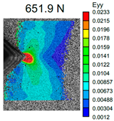 | 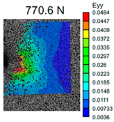 |  | 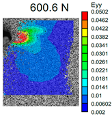 |
| Crack opening |  | 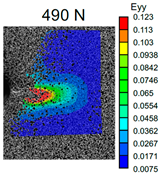 | 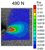 | 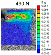 |
| Bending Modulus (GPa) | Bending Strength (MPa) | Resilience (J*m−3) | |
|---|---|---|---|
| Type C 04 | |||
| Type C 08 | |||
| Type C + CF 04 | |||
| Type C + CF 08 | |||
| Type C + GF 04 | |||
| Type C + GF 08 | |||
| Type C + BF 04 | |||
| Type C + BF 08 |
Disclaimer/Publisher’s Note: The statements, opinions and data contained in all publications are solely those of the individual author(s) and contributor(s) and not of MDPI and/or the editor(s). MDPI and/or the editor(s) disclaim responsibility for any injury to people or property resulting from any ideas, methods, instructions or products referred to in the content. |
© 2024 by the authors. Licensee MDPI, Basel, Switzerland. This article is an open access article distributed under the terms and conditions of the Creative Commons Attribution (CC BY) license (https://creativecommons.org/licenses/by/4.0/).
Share and Cite
Lobov, E.; Vindokurov, I.; Tashkinov, M. Mechanical Properties and Performance of 3D-Printed Acrylonitrile Butadiene Styrene Reinforced with Carbon, Glass and Basalt Short Fibers. Polymers 2024, 16, 1106. https://doi.org/10.3390/polym16081106
Lobov E, Vindokurov I, Tashkinov M. Mechanical Properties and Performance of 3D-Printed Acrylonitrile Butadiene Styrene Reinforced with Carbon, Glass and Basalt Short Fibers. Polymers. 2024; 16(8):1106. https://doi.org/10.3390/polym16081106
Chicago/Turabian StyleLobov, Evgeniy, Ilia Vindokurov, and Mikhail Tashkinov. 2024. "Mechanical Properties and Performance of 3D-Printed Acrylonitrile Butadiene Styrene Reinforced with Carbon, Glass and Basalt Short Fibers" Polymers 16, no. 8: 1106. https://doi.org/10.3390/polym16081106
APA StyleLobov, E., Vindokurov, I., & Tashkinov, M. (2024). Mechanical Properties and Performance of 3D-Printed Acrylonitrile Butadiene Styrene Reinforced with Carbon, Glass and Basalt Short Fibers. Polymers, 16(8), 1106. https://doi.org/10.3390/polym16081106