
The Effect of Resin Type and Placement Technique on the Hardness of Resin-Based Composites Polymerized with LED and UV Light-Curing Units


Abstract
1. Introduction
2. Materials and Methods
2.1. RBC Materials
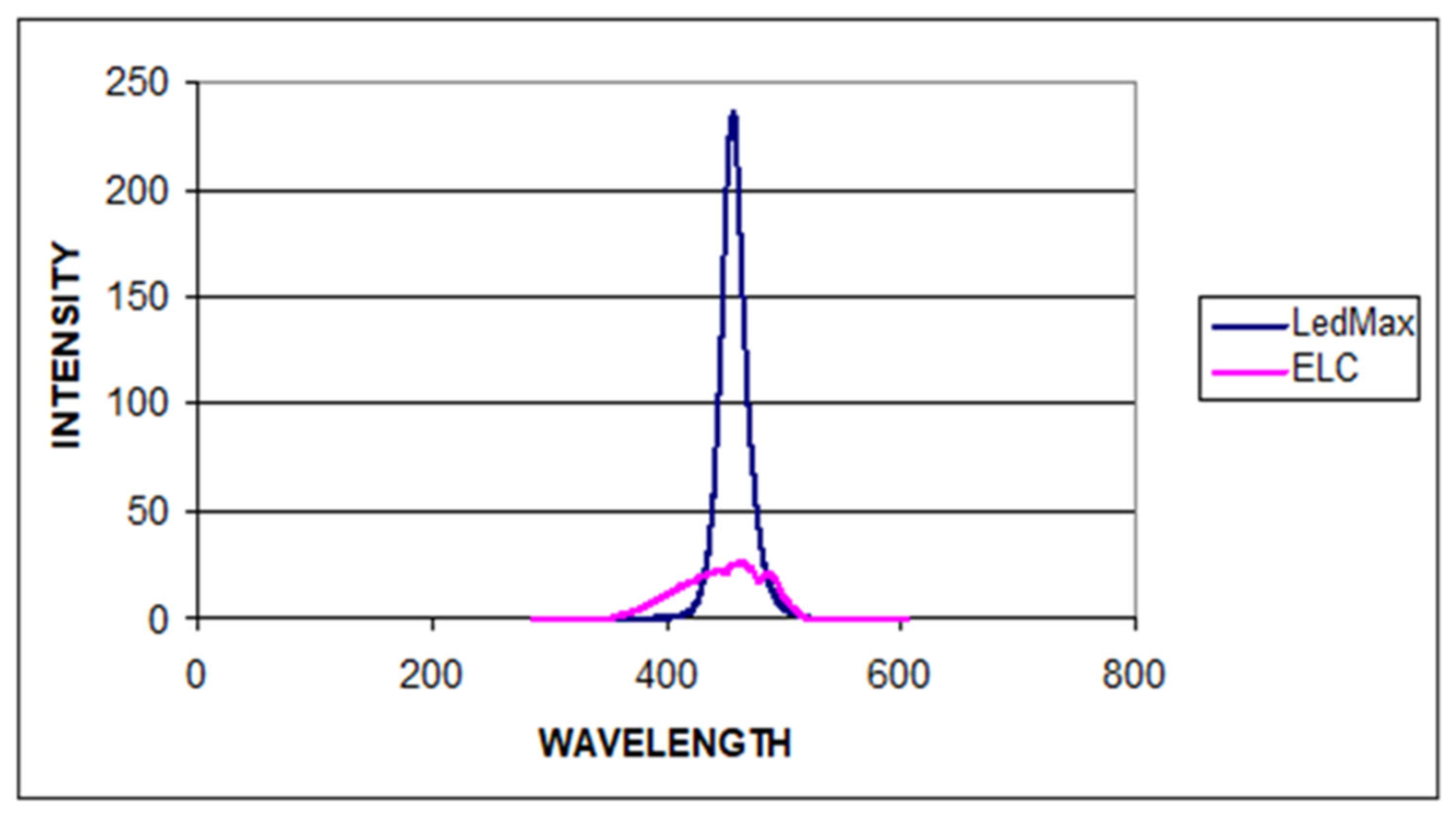
2.2. Light-Curing Unit and Assessment of Power Output, Emission Spectra, and the Distribution of Irradiance as a Function of Time
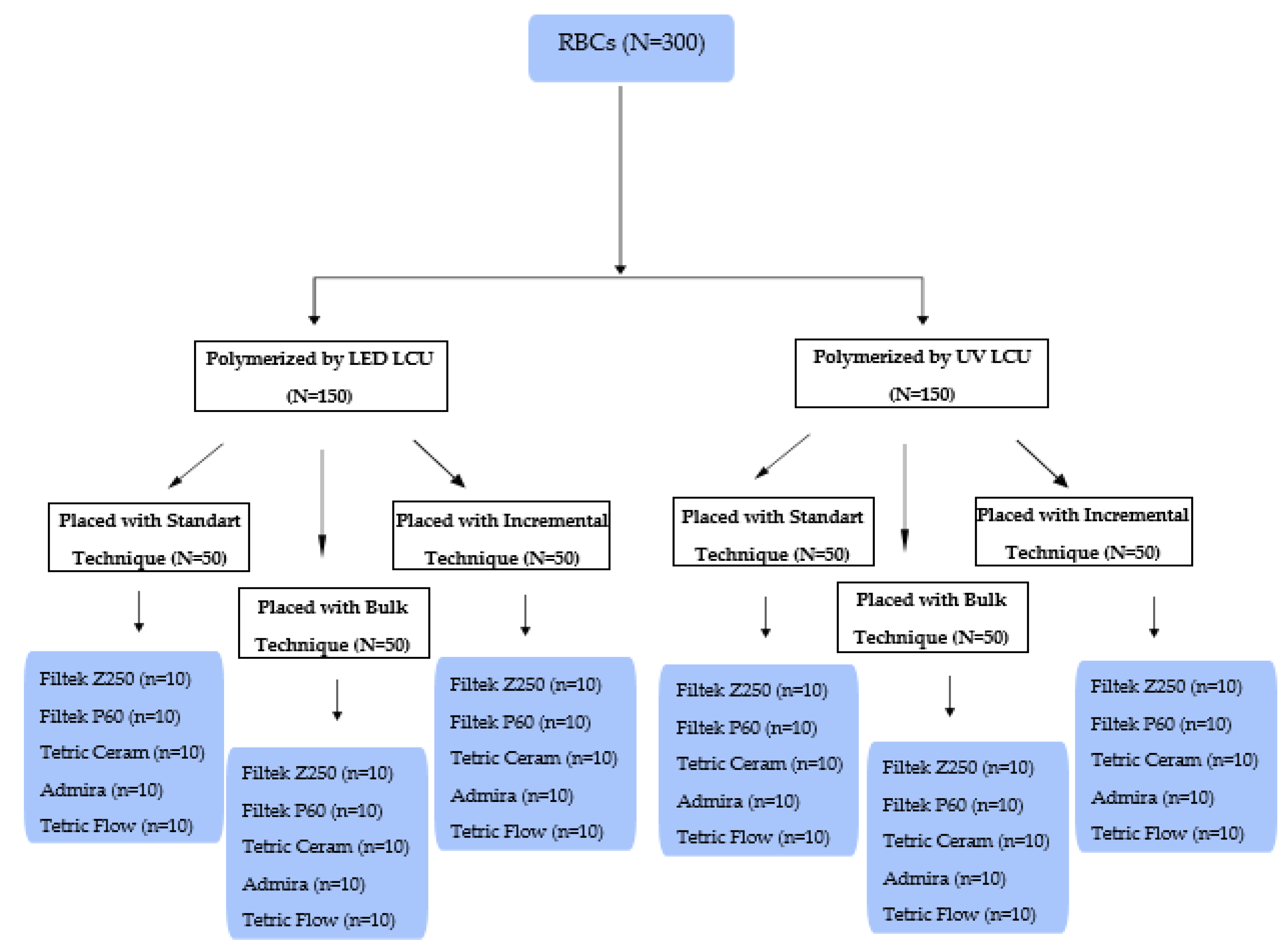
2.3. Placement Techniques and Polymerizing of the RBCs
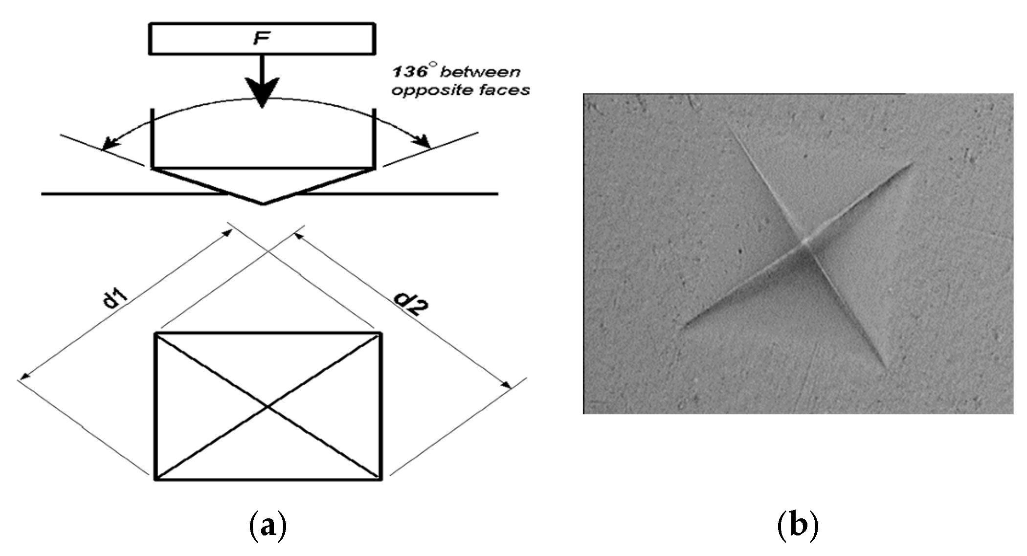
2.4. Determining the VHN
2.5. Statistical Analysis
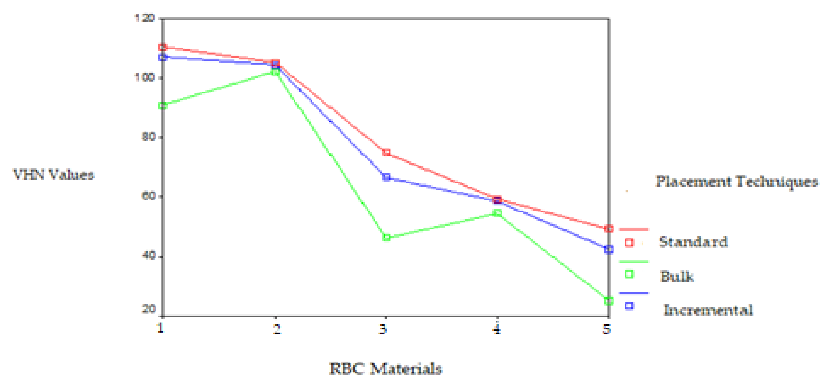
3. Results
4. Discussion
5. Conclusions
Author Contributions
Funding
Informed Consent Statement
Data Availability Statement
Acknowledgments
Conflicts of Interest
References
- Felix, C.A.; Price, R.B. The effect of distance from light source on light intensity from curing lights. J. Adhes. Dent. 2003, 5, 283–291. [Google Scholar]
- Bilge, K.; İpek, İ. Effects of different LED light curing units on the degree of conversion and microhardness of different composites: FT-IR and SEM-EDX analysis. Polym. Bull. 2024, 81, 13825–13838. [Google Scholar] [CrossRef]
- Arikawa, H.; Takahashi, H.; Kanie, T.; Ban, S. Effect of various visible light photoinitiators on the polymerization and color of light-activated resins. Dent. Mater. J. 2009, 28, 454–460. [Google Scholar] [CrossRef]
- Helvatjoglu-Antoniades, M.; Papadogiannis, Y.; Lakes, R.S.; Dionysopoulos, P.; Papadogiannis, D. Dynamic and static elastic moduli of packable and flowable composite resins and their development after initial photo curing. Dent. Mater. 2006, 22, 450–459. [Google Scholar] [CrossRef] [PubMed]
- Jakupović, S.; Pervan, N.; Mešić, E.; Gavranović-Glamoč, A.; Bajsman, A.; Muratović, E.; Kazazić, L.; Kantardžić-Kovačević, A. Assessment of Microhardness of Conventional and Bulk-Fill Resin Composites Using Different Light-Curing Intensity. Polymers 2023, 15, 2250. [Google Scholar] [CrossRef]
- Georgiev, G.; Dikova, T. Hardness Investigation of Conventional, Bulk Fill and Flowable Dental Composites. J. Achiev. Mater. Manuf. Eng. 2021, 109, 68–77. [Google Scholar] [CrossRef]
- Abed, Y.A.; Sabry, H.A.; Alrobeigy, N.A. Degree of conversion and surface hardness of bulkfill composite versus incremental fill composite. Tanta. Dent. J. 2015, 12, 71–80. [Google Scholar] [CrossRef]
- Kwon, Y.; Ferracane, J.; Lee, I.B. Effect of layering methods, composite type, and flowable liner on the polymerization shrinkage stress of light cured composites. Dent. Mater. 2012, 28, 801–809. [Google Scholar] [CrossRef]
- Bicalho, A.A.; Valdívia, A.D.; Barreto, B.C.; Tantbirojn, D.; Versluis, A.; Soares, C.J. Incremental filling technique and composite material-part II: Shrinkage and shrinkage stresses. Oper. Dent. 2014, 39, E83–E92. [Google Scholar] [CrossRef]
- Al Nahedh, H.N.A.; Al-Senan, D.F.; Alayad, A.S. The effect of different light curing units and tip distances on the polymerization efficiency of bulk-fill materials. Oper. Dent. 2022, 47, E197–E210. [Google Scholar] [CrossRef]
- Park, J.; Chang, J.; Ferracane, J.; Lee, I.B. How should composite be layered to reduce shrinkage stress: Incremental or bulk filling? Dent. Mater. 2008, 24, 1501–1505. [Google Scholar] [CrossRef] [PubMed]
- Bucuta, S.; Ilie, N. Light transmittance and micromechanical properties of bulk fill vs. conventional resin-based composites. Clin. Oral Investig. 2014, 18, 1991–2000. [Google Scholar] [CrossRef] [PubMed]
- Al Shaafi, M.M. Factors affecting polymerization of resin-based 5 composites: A literature review. Saudi. Dent. J. 2017, 29, 48–58. [Google Scholar] [CrossRef]
- Santini, A.; Gallegos, I.T.; Felix, C.M. Photoinitiators in dentistry: A review. Prim. Dent. J. 2013, 2, 30–33. [Google Scholar] [CrossRef]
- Ruyter, I.E.; Øysæd, H. Conversion in different depths of ultraviolet and visible light activated composite materials. Acta. Odontol. Scand. 1982, 40, 179–192. [Google Scholar] [CrossRef]
- Cook, W.D. Curing efficiency and ocular hazards of dental photopolymerization sources. Biomaterials 1986, 7, 449–454. [Google Scholar] [CrossRef]
- Harlow, J.E.; Rueggeberg, F.A.; Labrie, D.; Sulliva, B.; Price, R.B. Transmission of violet and blue light through conventional (layered) and bulk cured resin-based composites. J. Dent. 2016, 53, 44–50. [Google Scholar] [CrossRef]
- Hogarth, A.; Newcomb, G.M. The effect of long-wave ultraviolet radiation on gingival Langerhans cells. Aust. Dent. J. 1983, 28, 174–178. [Google Scholar] [CrossRef]
- Tanoue, N.; Matsumura, H.; Atsuta, M. Curing depth of a composite veneering material polymerized with seven different laboratory photo-curing units. J. Oral Rehabil. 1998, 25, 199–203. [Google Scholar] [CrossRef]
- Stansbury, J.W. Curing dental resins and composites by photopolymerization. J. Esthet. Dent. 2000, 12, 300–308. [Google Scholar] [CrossRef]
- Pilo, R.; Oelgiesser, D.; Cardash, H.S. A survey of output intensity and potential for depth of cure among light-curing units in clinical use. J. Dent. 1999, 27, 235–241. [Google Scholar] [CrossRef] [PubMed]
- Danesh, G.; Davids, H.; Reinhardt, K.J.; Ott, K.; Schäfer, E. Polymerisation characteristics of resin composites polymerised with different curing units. J. Dent. 2004, 32, 479–488. [Google Scholar] [CrossRef] [PubMed]
- Tarle, Z.; Meniga, A.; Knezevic, A.; Sutalo, J.; Ristic, M.; Pichler, G. Composite conversion and temperature rise using a conventional, plasma arc, and an experimental blue LED curing unit. J. Oral Rehabil. 2002, 29, 662–667. [Google Scholar] [CrossRef]
- Hofmann, N.; Hugo, B.; Klaiber, B. Effect of irradiation type (LED or QTH) on photo activated composite shrinkage strain kinetics, temperature rise, and hardness. Eur. J. Oral Sci. 2002, 110, 471–479. [Google Scholar] [CrossRef]
- Mills, R.W.; Jandt, K.D.; Ashworth, S.H. Dental composite depth of cure with halogen and blue light emitting diode technology. Br. Dent. J. 1999, 186, 388–391. [Google Scholar] [CrossRef]
- Price, R.B.; Felix, C.A.; Andreou, P. Third-generation vs. a second-generation LED curing light: Effect on Knoop micro-hardness. Compend. Contin. Educ. Dent. 2006, 27, 490–496. [Google Scholar]
- Gomes, G.M.; Calixto, A.L.; Santos, F.A.; Gomes, O.M.M.; D’Alpino, P.H.P.; Gomes, J.C. Hardness of a bleaching-shade resin composite polymerized with different light-curing sources. Braz. Oral Res. 2006, 20, 337–341. [Google Scholar] [CrossRef]
- Esmaeili, B.; Safarcherati, H.; Vaezi, A. Hardness Evaluation of Composite Resins Cured with QTH and LED. J. Dent. Res. Dent. Clin. Dent. Prospect. 2014, 8, 40–44. [Google Scholar]
- Leprince, J.; Devaux, J.; Mullier, T.; Vreven, J.; Leloup, G. Pulpal-temperature rise and polymerization efficiency of LED curing lights. Oper Dent. 2010, 35, 220–230S. [Google Scholar] [CrossRef]
- Giorgi, M.C.; Aguiar, F.H.; Soares, L.E.; Martin, A.A.; Liporoni, P.C.; Paulillo, L.A. Does an additional UV LED improve the degree of conversion and Knoop Hardness of light-shade composite resins? Eur. J. Dent. 2012, 6, 396–401. [Google Scholar] [CrossRef]
- Leonard, D.L.; Charlton, D.G.; Roberts, H.W.; Cohen, M.E. Polymerization efficiency of LED curing lights. J. Esthet. Restor. Dent. 2002, 14, 286–295. [Google Scholar] [CrossRef] [PubMed]
- Ferracane, J.L.; Mitchem, J.C.; Condon, J.R.; Todd, R. Wear and marginal breakdown of composites with various degrees of cure. J. Dent. Res. 1997, 76, 1508–1516. [Google Scholar] [CrossRef] [PubMed]
- Besnault, C.; Attal, J.P. Simulated oral environment and microleakage of Class II resin based composite and sandwich restorations. Am. J. Dent. 2003, 16, 186–190. [Google Scholar]
- Galvao, M.R.; Caldas, S.G.; Bagnato, V.S.; Rastelli, A.N.; Andrade, M.F. Evaluation of degree of conversion and hardness of dental composites photoactivated with different light guide tips. Eur. J. Dent. 2013, 7, 86–93. [Google Scholar] [PubMed]
- Poskus, L.T.; Placido, E.; Cardoso, P.E. Influence of placement techniques on Vickers and Knoop hardness of Class II composite resin restorations. Dent. Mater. 2004, 20, 726–732. [Google Scholar] [CrossRef]
- Endruweit, A.; Johnson, M.S.; Long, A. Curing of composite components by ultraviolet radiation: A review. Polym. Compos. 2006, 27, 119–128. [Google Scholar] [CrossRef]
- Kumar, J.; Singh, D.; Kalsi, N.S.; Kumar, S. Role of Alloying Elements as Reinforcements during Fabrication of Aluminium Metal Matrix Composites. J. Manage. Eng. Sci. 2025, 2, 1–21. [Google Scholar]
- Sakaguchi, R.; Ferracane, J.; Powers, J. Testing of Dental Materials and Biomechanics. In Craig’s Restorative Dental Materials, 14th ed.; Elsevier: Amsterdam, The Netherlands, 2019; pp. 75–77. [Google Scholar]
- Sharkey, S.; Ray, N.; Burke, F.; Ziada, H.; Hannigan, A. Surface hardness of light-activated resin composites cured by two different visible-light sources: An in vitro study. Quint. Int. 2001, 32, 401–405. [Google Scholar]
- Davidson-Kaban, S.S.; Davidson, C.L.; Feilzer, A.J.; de Gee, A.J.; Erdilek, N. The effect of curing light variations on bulk curing and wall-to-wall quality of two types and various shades of resin composites. Dent. Mater. 1997, 13, 344–352. [Google Scholar] [CrossRef]
- Melo, R.A.; Bispo, A.S.L.; Barbosa, G.A.; Galvão, M.R.; de Assunção, I.V.; Souza, R.O.A.; Borges, B.C.D. Morphochemical characterization, microhardness, water sorption, and solubility of regular viscosity bulk fll and traditional composite resins. Microsc. Res. Tech. 2019, 82, 1500–1506. [Google Scholar] [CrossRef]
- El Gezawi, M.; Kaisarly, D.; Al-Saleh, H.; ArRejaie, A.; Al-Harbi, F.; Kunzelmann, K. Degradation potential of bulk versus incrementally applied and indirect composites: Color, microhardness, and surface deterioration. Oper. Dent. 2016, 41, e195–e208. [Google Scholar] [CrossRef] [PubMed]
- Emami, N.; Söderholm, K.J.; Berglund, L.A. Effect of light power density variations on bulk curing properties of dental composites. J. Dent. 2003, 31, 189–196. [Google Scholar] [CrossRef]
- Manhart, J.; Kunzelmann, K.H.; Chen, H.Y.; Hickel, R. Mechanical properties of new composite restorative materials. J. Biomed. Mater. Res. 2000, 53, 353–361. [Google Scholar] [CrossRef]
- Scougall-Vilchis, R.J.; Hotta, Y.; Hotta, M.; Idono, T.; Yamamoto, K. Examination of composite resins with electron microscopy, microhardness tester and energy dispersive X-ray microanalyzer. Dent. Mater. J. 2009, 28, 102–112. [Google Scholar] [CrossRef]
- Garoushi, S.; Vallittu, P.; Shinya, A.; Lassila, L. Influence of increment thickness on light transmission, degree of conversion and micro hardness of bulk fill composites. Odontology 2016, 104, 291–297. [Google Scholar] [CrossRef]
- Saati, K.; Khansari, S.; Mahdisiar, F.; Valizadeh, S. Evaluation of microhardness of two bulk-fill composite resins compared to a conventional composite resin on surface and in diferent depths. J. Dent. 2022, 23, 58. [Google Scholar]
- Putignano, A.; Tosco, V.; Monterubbianesi, R.; Vitiello, F.; Gatto, M.L.; Furlani, M.; Giuliani, A.; Orsini, G. Comparison of three different bulk-filling techniques for restoring class II cavities: μCT, SEM-EDS combined analyses for margins and internal fit assessments. J. Mech. Behav. Biomed. Mater. 2021, 124, 104812. [Google Scholar] [CrossRef]
- Duratbegović, D.; Pervan, N.; Jakupović, S.; Kobašlija, S. The Effects of Intensity, Exposure Time, and Distance of Polymerization Light on Vickers Microhardness and Temperature Rise of Conventional Resin-Based Composite. Polymers 2024, 16, 3175. [Google Scholar] [CrossRef]
- Cavalcante, L.M.; Valentino, T.A.; Carlini, B., Jr.; Silikas, N.; Pimenta, L.A. Influence of different exposure time required to stabilize hardness values of composite resin restorations. J. Contemp. Dent. Pract. 2009, 10, 42–50. [Google Scholar] [CrossRef]
- Zorzin, J.; Maier, E.; Harre, S.; Fey, T.; Belli, R.; Lohbauer, U.; Petschelt, A.; Taschner, M. Bulk-fill resin composites: Polymerization properties and extended light curing. Dent. Mater. 2015, 31, 293–301. [Google Scholar] [CrossRef]
- Poulos, J.G.; Styner, D.L. Curing lights: Changes in intensity output with use over time. Gen. Dent. 1997, 45, 70–73. [Google Scholar] [PubMed]
- Park, S.H.; Krejci, I.; Lutz, F. Hardness of celluloid strip-finished or polished composite surfaces with time. J. Prosthet. Dent. 2000, 83, 660–663. [Google Scholar] [CrossRef] [PubMed]
- Monterubbianesi, R.; Tosco, V.; Sabbatini, S.; Orilisi, G.; Conti, C.; Özcan, M.; Orsini, G.; Putignano, A. How Can Different Polishing Timing Influence Methacrylate and Dimethacrylate Bulk Fill Composites? Evaluation of Chemical and Physical Properties. Biomed. Res. Int. 2020, 9, 1965818. [Google Scholar] [CrossRef] [PubMed]


| Material | Filtek Z250 | Filtek P60 | Tetric Ceram | Admira | Tetric Flow |
|---|---|---|---|---|---|
| Manufacturer | 3M, ESPE, St. Paul, MN, USA | 3M, ESPE, St. Paul, MN, USA | Ivoclar Vivadent, Schaan, Liechtenstein | Voco GmbH, Cuxhaven, Germany | Ivoclar Vivadent, Schaan, Liechtenstein |
| Type | Microhybrid | Packable, condensable, moldable | Fine-particle hybrid | High-viscosity ORMOCER | Flowable low viscosity |
| Resin Matrix | Bis-GMA, UDMA, Bis-EMA | Bis-GMA, UDMA, Bis-EMA | Bis-GMA, UDMA, TEGDMA | Inorganic–organic copolymers (ORMOCER), Bis-GMA, diurethane (aliphatic and aromatic) DMA, BHT, TEGDMA | Bis-GMA, UDMA, TEGDMA |
| Inorganic Filler Type | Zirconia/Silica | Zirconia/Silica | Barium glass, ytterbium trifluoride, barium alumino-fluoro-silicate glass, highly dispersed silicon dioxide, and spheroid mixed oxide | Barium aluminum-boro-silicate glass | Barium glass, ytterbium trifluoride, barium alumino-fluoro-silicate glass, highly dispersed silicon dioxide, and spheroid mixed oxide |
| Filler Loading (weight %) | 82 | 80 | 79 | 78 | 64.6 |
| Filler Content (% by volume) | 60 | 61 | 60 | 56 | 39.7 |
| Average Particle Size (μm) | 0.01–3.5 μm (mean 0.6) | 0.01–3.5 μm (mean 0.6) | 0.04–3 μm (mean 0.7) | 0.04–1.2 μm (mean 0.7) | 0.04–3 μm (mean 0.7) |
| Co-initiator Absorption Within < 410 nm | No | no | unknown | no | Unknown |
| Curing Time(s) Standard Method | 20 s | 20 s | 40 s | 40 s | 20 s |
| Light Source | Hilux Ledmax 1055 (LED LCU) | ELC-410 (UV LCU) |
|---|---|---|
| Manufacturer | Benlioğlu Dental Inc., Ankara, Türkiye | Eluv.Electro-Lite, Danbury, USA |
| Light Intensity (mW/cm2) | * 229.153 mW/cm2 | * 26.106 mW/cm2 |
| Lamp Output (mW/cm2) | 1350–1500 mW/cm2 (2nd generation) | ** UV Light Lamp Output 90 mW/cm2 ** Visible Light Lamp Output 600 mW/cm2 |
| Emission Wavelength Range (nm) | * 418.724–512.268 nm | * 374.253–530.313 nm |
| Peak Wavelength (nm) | * 458.595 nm | * 465.036 nm |
| Light Guide Type and Diameter (mm) | ** 11 mm 60° bent fiber optic | ** 11 mm curvature |
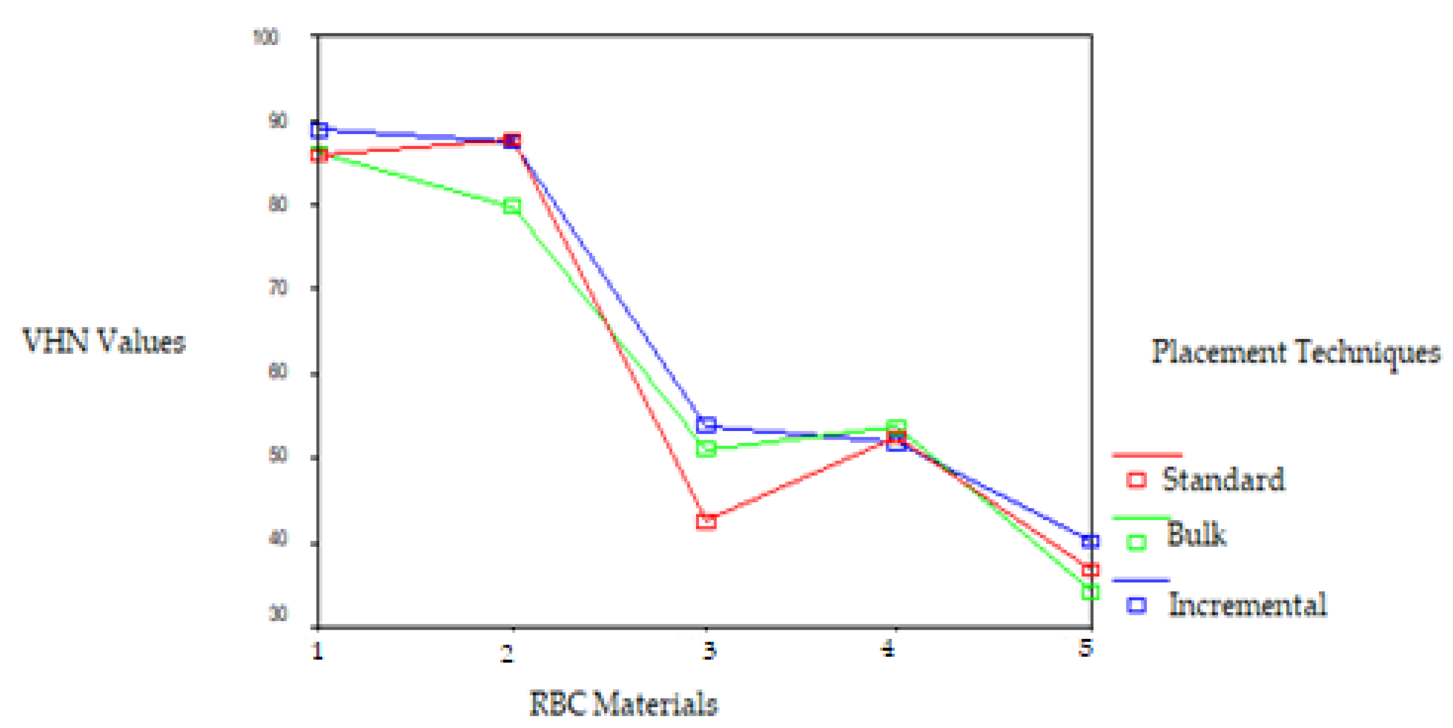
| LED LCU | TOP SURFACE Mean VHN ± sd (kgf/mm2) | BOTTOM SURFACE Mean VHN ± sd (kgf/mm2) | ||||
|---|---|---|---|---|---|---|
| RBCs | Standard | Bulk | Incremental | Standard | Bulk | Incremental |
| (S) | (S) | (S) | (S) | (S) | (S) | |
| Filtek Z 250 | 110.33 (1.49) | 90.94 (0.89) | 107.20 a (8.75) | 86.26 Cb (1.98) | 86.36 Cc (1.46) | 90.06 (1.40) |
| Filtek P 60 | 105.13 A (2.41) | 102.02 (2.02) | 104.33 Aa (1.75) | 83.71 DEb (2.62) | 85.56 Dc (1.29) | 82.52 E (2.14) |
| Tetric Ceram | 75.0 (1.11) | 46.49 (0.74) | 66.66 (0.53) | 56.62 (1.51) | 52.08 d (1.74) | 54.39 (0.55) |
| Admira | 59.49 B (1.26) | 54.64 (1.48) | 58.73 B (1.53) | 50.36 F (1.28) | 50.30 Fd (1.45) | 48.58 (0.57) |
| Tetric Flow | 49.37 (0.50) | 25.16 (0.45) | 42.36 (0.35) | 36.83 (0.37) | 34.98 (0.36) | 31.95 (0.66) |
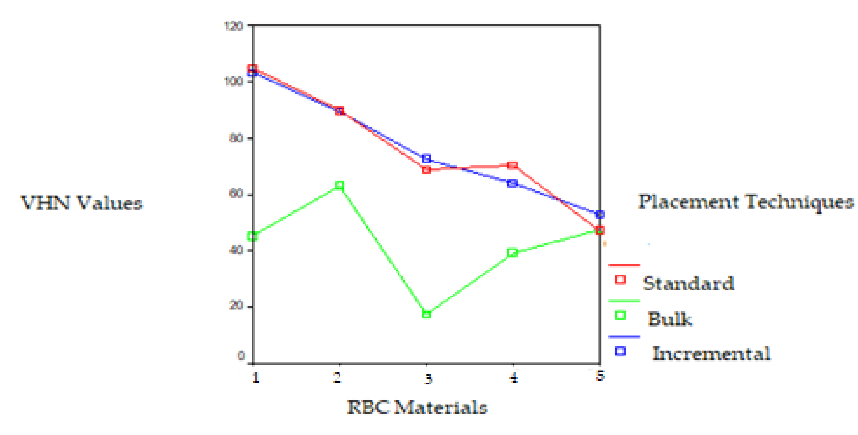
| UV LCU | TOP SURFACE Mean VHN ± sd (kgf/mm2) | BOTTOM SURFACE Mean VHN ± sd (kgf/mm2) | ||||
|---|---|---|---|---|---|---|
| RBC | Standard | Bulk | Incremental | Standard | Bulk | Incremental |
| (S) | (S) | (S) | (S) | (S) | (S) | |
| Filtek Z 250 | 104.86 A (1.45) | 45.27 b (0.92) | 103.26 A (2.18) | 85.76 Dc (1.28) | 86.12 D (1.41) | 88.87 (1.69) |
| Filtek P 60 | 89.76 B (0.85) | 63.24 (0.32) | 89.45 B (1.95) | 87.74 Ec (1.15) | 79.80 (0.69) | 87.40 E (1.93) |
| Tetric Ceram | 68.74 a (1.48) | 33.87 (0.83) | 72.90 (2.02) | 47.42 (1.27) | 51.02 d (0.94) | 53.96 (1.25) |
| Admira | 70.50 a (0.85) | 39.48 (0.36) | 63.99 (1.00) | 52.40 FG (0.33) | 53.61 Fd (0.42) | 51.73 G (0.57) |
| Tetric Flow | 47.42 C (0.42) | 47.67 Cb (0.82) | 52.86 (0.47) | 36.76 (0.84) | 34.20 (0.44) | 40.16 (0.49) |
Disclaimer/Publisher’s Note: The statements, opinions and data contained in all publications are solely those of the individual author(s) and contributor(s) and not of MDPI and/or the editor(s). MDPI and/or the editor(s) disclaim responsibility for any injury to people or property resulting from any ideas, methods, instructions or products referred to in the content. |
© 2025 by the authors. Licensee MDPI, Basel, Switzerland. This article is an open access article distributed under the terms and conditions of the Creative Commons Attribution (CC BY) license (https://creativecommons.org/licenses/by/4.0/).
Share and Cite
Duman, A.N.; Dogan, A. The Effect of Resin Type and Placement Technique on the Hardness of Resin-Based Composites Polymerized with LED and UV Light-Curing Units. Polymers 2025, 17, 774. https://doi.org/10.3390/polym17060774
Duman AN, Dogan A. The Effect of Resin Type and Placement Technique on the Hardness of Resin-Based Composites Polymerized with LED and UV Light-Curing Units. Polymers. 2025; 17(6):774. https://doi.org/10.3390/polym17060774
Chicago/Turabian StyleDuman, Ayse Nurcan, and Arife Dogan. 2025. "The Effect of Resin Type and Placement Technique on the Hardness of Resin-Based Composites Polymerized with LED and UV Light-Curing Units" Polymers 17, no. 6: 774. https://doi.org/10.3390/polym17060774
APA StyleDuman, A. N., & Dogan, A. (2025). The Effect of Resin Type and Placement Technique on the Hardness of Resin-Based Composites Polymerized with LED and UV Light-Curing Units. Polymers, 17(6), 774. https://doi.org/10.3390/polym17060774