Article

The Development of an Electric-Driven Control System for a High-Speed Precision Planter Based on the Double Closed-Loop Fuzzy PID Algorithm

1
College of Engineering, Anhui Agricultural University, Hefei 230036, China
2
Hefei Comprehensive National Science Center, Institute of Artificial Intelligence, Hefei 230036, China
3
Anhui Provincial Engineering Laboratory of Intelligent Agricultural Machinery, Hefei 230036, China
*
Author to whom correspondence should be addressed.
Agronomy 2022, 12(4), 945; https://doi.org/10.3390/agronomy12040945
Submission received: 12 March 2022 / Revised: 2 April 2022 / Accepted: 12 April 2022 / Published: 14 April 2022

Abstract

:
In order to solve the problems of traditional seeders, such as low seeding efficiency, tangled straw, a large amount of clay, easy ridge breakage in sowing operations, low qualified rate of high-speed seeding, and poor uniformity, this paper takes the pneumatic corn planter as the research object, the Beidou automatic driving unit as the carrier, the CAN (Controller Area Network) bus as the communication medium, and the double closed-loop fuzzy PID (proportion-integral-derivative) algorithm as the control core and designs a high-speed precision corn seeding control system based on Beidou navigation. It solves the problems that exist in traditional planters. In the bench experiment, the stability of the system is judged by comparing the motor control accuracy with ordinary PID and measuring the motor response time of the system at different speeds. The bench test results show that when the theoretical seeding speed is 0~34 r·min−1, the response time of the motor is shortened by 0.51 s compared with the ordinary PID control, and the error between the actual speed and the target value is less than 0.35%. The field experiment results show that when the unit runs for 5~13 km·h−1, the qualified rate of average planting spacing is greater than 95.81%, the reseeding rate is less than 10.11%, and the coefficient of variation is less than 16.72%, which complies with the standard of a corn sowing operation.

1. Introduction

The performance of a corn seeding system directly affects the seeding quality of the seeder. In order to overcome the relative slippage between the driving wheel of the mechanical seed metering system and the ground under the straw returning to the field, which leads to poor sowing quality [1,2], an electric-driven seed metering system has been increasingly and widely used. Moreover, low input, high efficiency, and sustainable development have put forward higher requirements for a precision corn seeding system [3]. How to realize the efficient matching between the electric-driven seed metering system and the tractor under the high-speed operation of the seeding unit has become a hot research topic.
The early electric-driven seed metering system used an encoder installed on the driving wheel of the unit and collected the speed of the driving wheel as the system input signal to drive the seed metering motor to complete the seed metering operation [4,5,6,7]. However, when the encoder is used to collect the speed of the unit while the weather is wet or the field is muddy, the driving wheel is easy to slip and the mud is blocked, resulting in an inaccurate speed measurement. After discovering the drawbacks of the encoder, many researchers have used the ground survey radar installed in the chassis of the unit or in front of the unit and used the principle of the Doppler effect to collect the speed of the unit [8,9]. In this way, the influence of ground wheel slip caused by sudden high humidity and rainy days can be avoided, and the error of radar speed measurement accuracy (<100 km·h−1) is less than 0.27 m·s−1, which has better speed measurement accuracy. However, although the use of ground survey radar overcomes the disadvantage of the ground wheel slipping and has high-speed measurement accuracy, because the ground survey radar collects ground echoes, it is easy to be unstable due to uneven ground in the field, resulting in an inaccurate speed measurement. With the advancement of agricultural science and technology, the mechanization of agriculture has gradually transformed into agricultural intelligence and modernization. GPS (Global Position System) has gradually replaced the sensor and has been applied to an electric-driven control system to measure the forward speed of the unit. A GPS sensor with a speed error accuracy of 0.3 m·s−1 is installed in the seeder unit, the satellite message sent by the GPS satellite can be received in real time, and the satellite message and real-time crew forward speed can be obtained by parsing the satellite message [10]. Although the GPS replaces the sensor, the inaccuracy of the forward speed of the unit caused by the external environment is reduced to a certain extent, but the response time problem of the motor itself caused by the speed switching has not been solved. To solve the problem of poor seeding quality caused by the motor speed response time, some domestic researchers started from the control algorithm for motor research, and PID (proportion-integral-derivative) is a widely used motor control method [11,12,13], such as single closed-loop PID, immune PID control algorithm, integral separation PID control algorithm, and double closed-loop PID fuzzy algorithm [14,15,16]. By setting the target speed, the error value is compensated in an algorithmic way, thereby improving the accuracy of seed metering, but no more research has been done on the motor control accuracy during acceleration and deceleration of the unit and switching between high and low speeds.
With the proposal of smart agriculture, the Beidou navigation system (BDS) independently developed by China has been gradually applied to agricultural production. The BDS is mainly used for precise navigation of agricultural machinery, precise operation of agricultural machinery, and fine management of agricultural production. At present, the accuracy of BDS will be better than 10 m and the speed measurement accuracy will be better than 0.2 m·s−1. The positioning accuracy in the Asia Pacific region will be better than 5 m, and the speed measurement accuracy will be better than 0.1 m·s−1. It is 0.17 m·s−1 higher than the radar accuracy introduced. Automatic driving technology is used for more than 90% of large farms by the BDS for agricultural production in China [17,18]. The high-speed precision seeding technology of corn under automatic driving requires the seeding device to maintain a high ground speed over 8 km·h−1. At the same time, the quantitative seeds are sown according to the planting spacing, row spacing uniformity and sowing depth required by agronomy, and the planting technology of deep fertilization, which can not only improve the uniformity of corn sowing, enhance the rationality between light, water, and fertilizer during the growth of corn, but also improve the efficiency of corn sowing and thus increase the yield per acre [19,20,21]. When the operation starts, the unit accelerates to stability, decelerates to stop at the field head, and stops at high and low speeds, which leads to the instability of the motor. So, this paper is mainly based on the automatic driving unit of BDS and develops a set of electric-driven seeding system that matches the tractor with high efficiency. Mainly by analyzing the longitude and latitude signals issued by BDS as the input source of the system signal and efficiently fitting the motor speed through the speed matching algorithm, the highest positioning accuracy can reach 0.02 m, and the speed accuracy error is less than 0.1 m·s−1. The system controls the seeding motor to complete the operation. There is no need to install additional sensors, which saves costs to a certain extent. In terms of motor control, the speed-position double closed-loop fuzzy PID algorithm is used to control the response time and accuracy of the motor, which improves the uniformity and accuracy of the unit’s variable speed sowing over high-speed 8 km·h−1.
The main contributions of this paper are as follows:
  • Directly analyze the longitude and latitude signal sent by BDS as the system signal input source to drive the motor to complete the sowing operation without installing additional sensors, which saves the production cost to a certain extent.
  • The double closed-loop fuzzy PID control algorithm is used to accurately control the motor and shorten the response time of the motor.
  • CAN bus (Controller Area Network) is used as the communication medium of the system to improve the fault tolerance and scalability of the system.

2. Materials and Methods

2.1. High-Speed Precision Seeding Control System

2.1.1. Overall Structure of Seeding Unit

As shown in Figure 1, the seeding unit is mainly composed of an autonomous driving tractor and a pneumatic seeder. The BDS equipment is installed on the roof of the tractor to receive satellite signals for precise navigation. The pneumatic seeder is installed behind the tractor through three-point suspension and is mainly composed of a fertilizer subsoiling spade, a seed box, a fertilizer box, a double disc opener, a soil compaction wheel, and an electric-driven seed meter device. A pneumatic seeder lift is controlled by a hydraulic system. The work flow of the whole unit is to start the automatic driving, and the tractor drives the planter to work to realize the integration of ditching, fertilizing, sowing, and covering soil.

2.1.2. System Working Overview

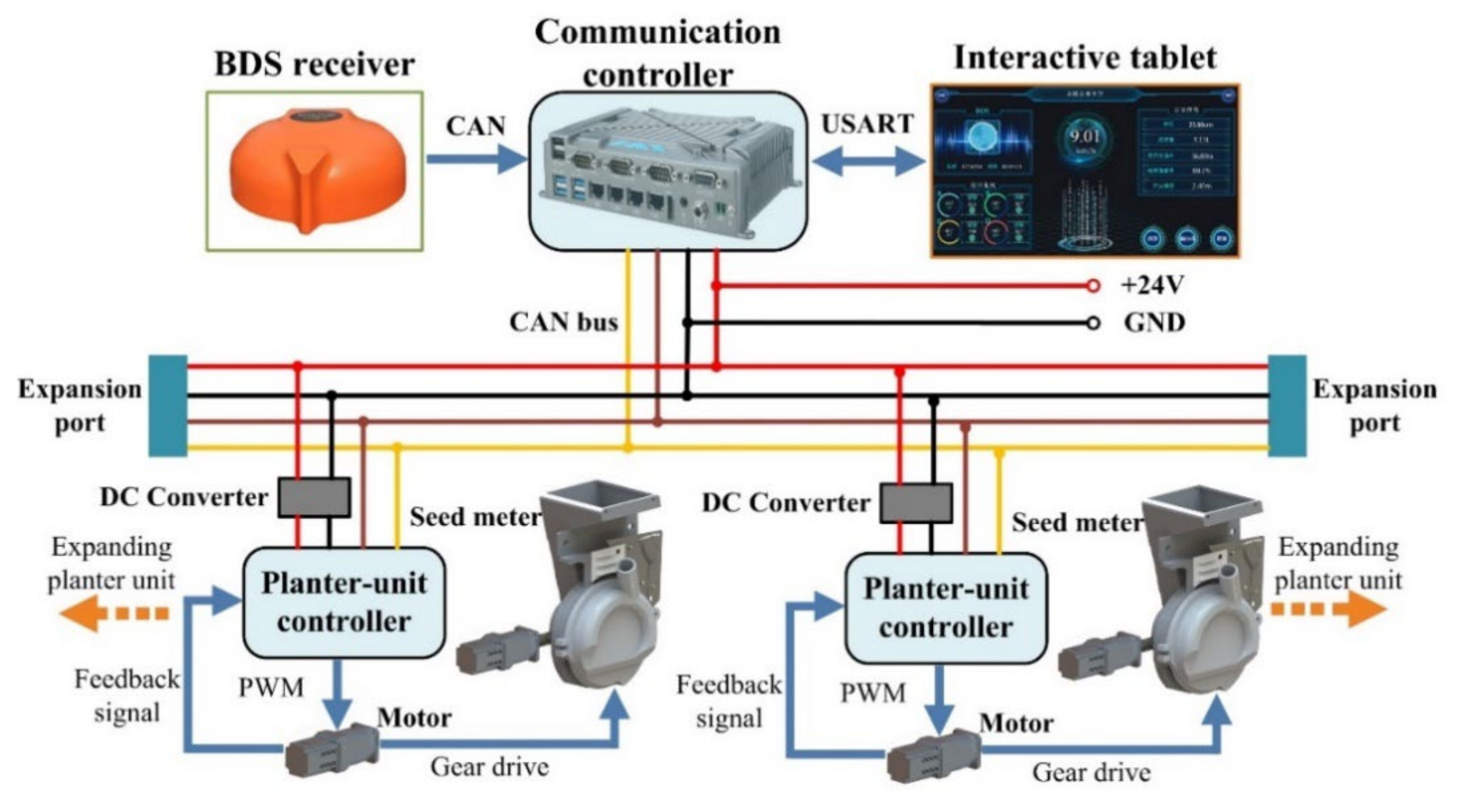
The proposed CAN bus implementation of the electric-driven seeding control system (EDS) based on BDS is illustrated in Figure 2. As shown in Figure 2, the EDS consists of a BDS receiver (Huida Technology Development Co., Ltd., Jingzhou, China), a communication controller (Genius Technology, Shanghai, China), an interactive tablet, a 24 V power supply, DC converters (EVEPS Technology LLC, Shenzhen, China), seed-meter dosing motors (Times Brilliant Electrical LLC, Beijing, China), planter-unit controllers, and seed meters (Anhui Province Engineering Laboratory of Intelligent Agricultural Machinery and Equipment, Hefei, China). The electric-driven seed meter includes a DC converter, a DC servo motor, a reducer, and a photoelectric sensor. The interactive tablet and communication controller are connected through USART (Universal Synchronous/Asynchronous Receiver/Transmitter). The CAN bus implementation of EDS control offers good planter unit extensibility by means of the expansion ports, which allows additional planter units to be added freely.
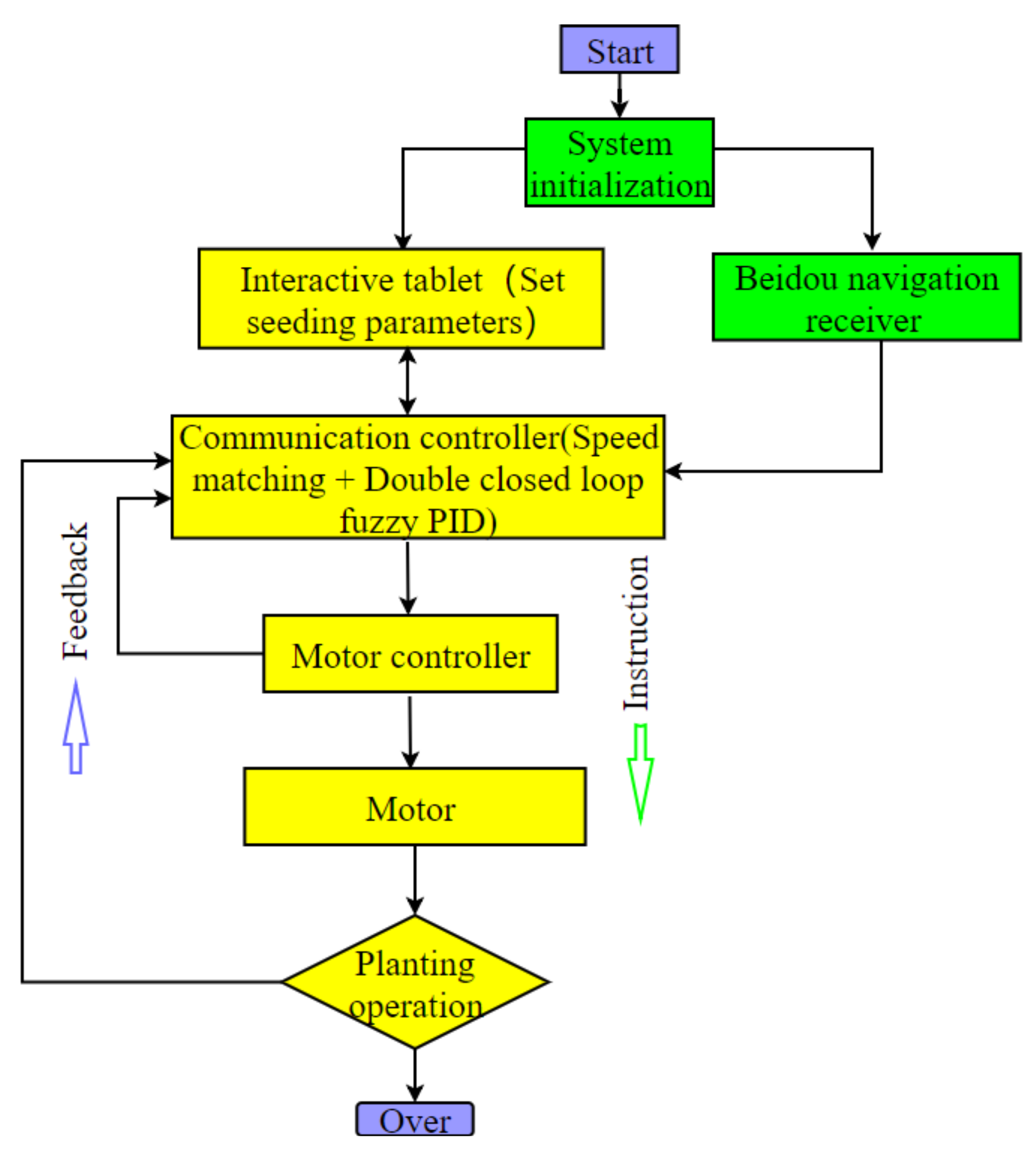
Figure 3 shows the EDS flow. The communication controller is the core part of the entire system and the computing center, including BDS location information obtained by the controller, the seeding operation parameters set by the interactive tablet, and the real-time status of the motor feedback by the motor via the CAN bus. On the one hand, after integrating the information of each part, the driving instructions of the four motors are transmitted through the CAN bus, which is based on the ISO-1783 protocol, which is used to read, analyze, and control the sowing. The double closed-loop fuzzy PID is used to control the motor speed, and the control system records the sowing speed and driving speed in real time. On the other hand, the tractor’s operating speed, operating area, location, etc., are uploaded to the communication controller so that the driver can know the current operating status through the interactive tablet. During the above process, the BDS signal indicator and communication indicator will flash at the corresponding frequency, indicating that the system is working normally. The system receives BDS information in NMEA-0183 format through the CAN port, obtains BDS data in real time, analyzes and processes it through the communication controller data center, and sends the analysis results to the seed meter in the form of instructions. This machine is a four-row pneumatic no-tillage planting and fertilizing all-in-one machine. Each row of planters is driven independently by motors.

2.1.3. Relationship between Forward Speed and Dosing Motor Rotary Speed

The forward speed is used as the starting signal for the system operation, and the motor speed is used as the execution signal for the system operation. The mathematical relationship between the two is particularly important.
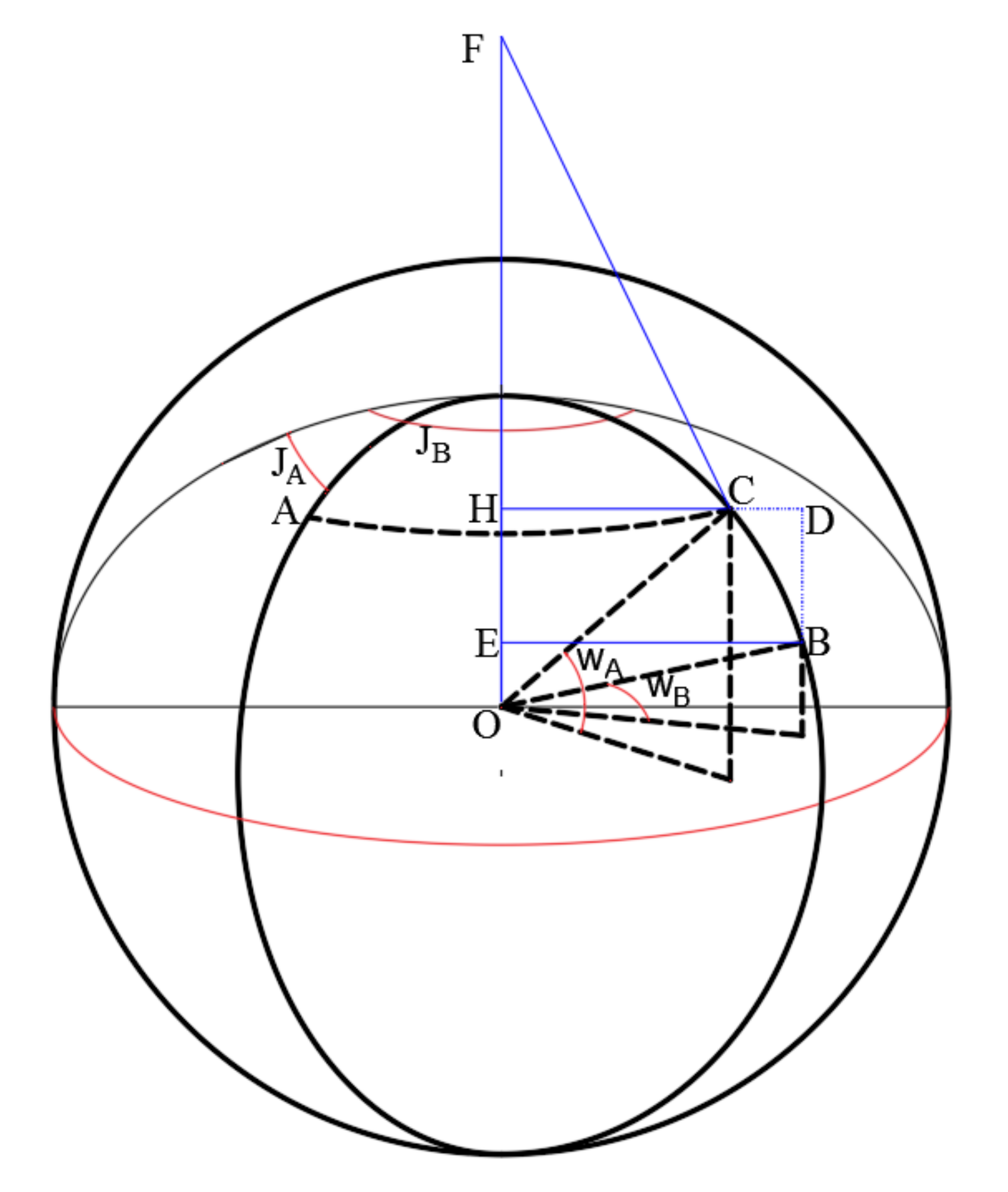
The principle of forward speed acquisition is mainly through the positioning data output by BDS. The positioning data is parsed by the NMEA-0183 protocol and transmitted by ASCII (American Standard Code for Information Interchange) code, mainly including BDGGA (BDS positioning information frame), BDGSA frame (current satellite information), BDGSV frame (Visible Beidou satellite information), BDRMC frame (recommended location information), BDVTG frame (ground speed information), and BDGLL frame (geodetic coordinate information) [22,23]. Among them, BDGGA contains the latitude and longitude coordinate information of the required seeding unit during operation. The communication controller receives BDGGA in real time, and the latitude and longitude of the two consecutive captures are set to A ( W A , J A ) and B ( W B , J B ), as shown in Figure 4, since the earth is regarded as a sphere. Points A and B are the positions of two points, respectively, where W is the latitude and J is the longitude, while the time difference between the two captures is T, and the distance between the two points is L 1 .
L 1 = 2 R × arcsin sin 2 W A W B 2 + cos W A × cos W B × sin 2 J A J B 2
V = L 1 T
The parameters required to obtain the motor speed are complex. In addition to the forward speed collected by the BDS equipment and the planting spacing parameters set in the communication controller, it is also necessary to combine the information, such as the number of holes in the seed meter and the reduction ratio between the motor and the seed meter. In this paper, a pneumatic 26-hole seed metering device is used. Based on the above information, the speed matching algorithm formula can be obtained, and the motor speed N can be calculated to realize sowing.
N = 1200 L V 2 a r s
where: a—number of seed meter holes, each (a = 26); r—seed disk radius, m; L—seed disk circumference, m; V—tractor forward speed, m/s; s—plant spacing, m; N—motor speed, r·min−1; reduction ratio 1:20.

2.2. Motor Control Algorithm Design

2.2.1. Model Establishment of Double Closed-Loop Fuzzy PID

The key to fuzzy control lies in the division of domain, degree of membership, and fuzzy level. This control method is especially suitable for multi-input, single-output control systems [24]. In order to ensure the quality of work and improve the anti-interference ability, the self-tuning fuzzy PID algorithm is used to control the servo integrated motor with speed-position double closed-loop control, the speed loop is used as the inner loop, the position loop is the outer loop, and the PWM (pulse width modulation) modulation method is used to realize the servo integrated motor adjustment speed. Figure 5 shows the double closed-loop speed control structure. The speed setpoint is compared with the feedback value. After incremental PID adjustment, the setpoint of position adjustment is output and compared with the actual detected position value. After the incremental PID adjustment, the appropriate duty cycle of PWM modulation is the output. At this time, when the system load changes, it can effectively suppress the speed fluctuation, improve the anti-interference ability during work, and ensure the quality of work.

2.2.2. Control Strategy Design

Figure 6 shows the self-tuning double closed-loop fuzzy PID control strategy structure. The difference e between the given speed n and the feedback speed n f and the rate of change e c of the difference are the inputs of the fuzzy controller. Both e and e c are accurate. After fuzzing the two, the fuzzy quantities E and E c are obtained, which are controlled by the fuzzy controller. After the rules are inferred and defuzzified, the modified parameters Δ K p ,   K i , Δ K d are obtained, and the three correction parameters are automatically and optimally adjusted in real time according to the running state of the motor so as to realize the self-tuning of PID control parameters.
Δ K d = j = 1 5 u j ( | E | f u z z y , | E c | f u z z y ) × K D j j = 1 5 u j ( | E | f u z z y , | E c | f u z z y )
Δ K p = j = 1 5 u j | E | f u z z y , | E c | f u z z y × K P j j = 1 5 u j | E | f u z z y , | E c | f u z z y
Δ K i = j = 1 5 u j | E | f u z z y , | E c | f u z z y ) × K I j j = 1 5 u j | E | f u z z y , | E c | f u z z y
Use self-tuning PID parameters K p , K i , and K d to determine the relationship between input e(t) and output u(t).
u t = Δ K p e t + Δ K i 0 t e t d t + Δ K d d e t d t
The system input variables E and E c have fuzzy subsets {NB, NS, ZO, PS, PB}, and output variables K p ,   K i , and K d have fuzzy subsets {NB, NM, NS, Z, PS, ZO, PS, PM, PB} so that E and E c are discretized and correspond to the fuzzy domain through the quantization factor, and the quantization factor of E can be obtained:
Δ K E = n E E ,    Δ K E c = n E c E c
Set the domain of each variable to [6], n E , n E c are fuzzy series, this paper takes n E = n E c = 6, and the input quantization factors are Δ K E = 7.8 , Δ K E c = 1.2 [17]. The speed loop fuzzy PID controller determines the appropriate K p , K i ,   and   K d according to different E and E c and achieves the optimal speed control effect through the parameters of the self-tuning controller. The control rules of input variables and output variables are as follows:
When E is larger, take a larger K p and smaller K d . At the same time, in order to prevent a bit of saturation and avoid large overshoot in the system response, the integral action should be removed; that is, K i = 0.
When E and E c are medium-sized, K p , K i , and K d should not be too large, and the smaller K p , K i , and K d should be selected to be moderate in order to ensure the system response speed.
When E is small, in order to make the system have good steady-state performance, the values of K i and K p should be increased. At the same time, to avoid system oscillation near the set value and consider the anti-interference performance of the system, K d is appropriately selected—usually a medium size [25,26,27,28,29,30].
To sum up, the fuzzy control rules are shown in Table 1.

2.3. Bench Test and Field Experiment

2.3.1. Bench Test Method

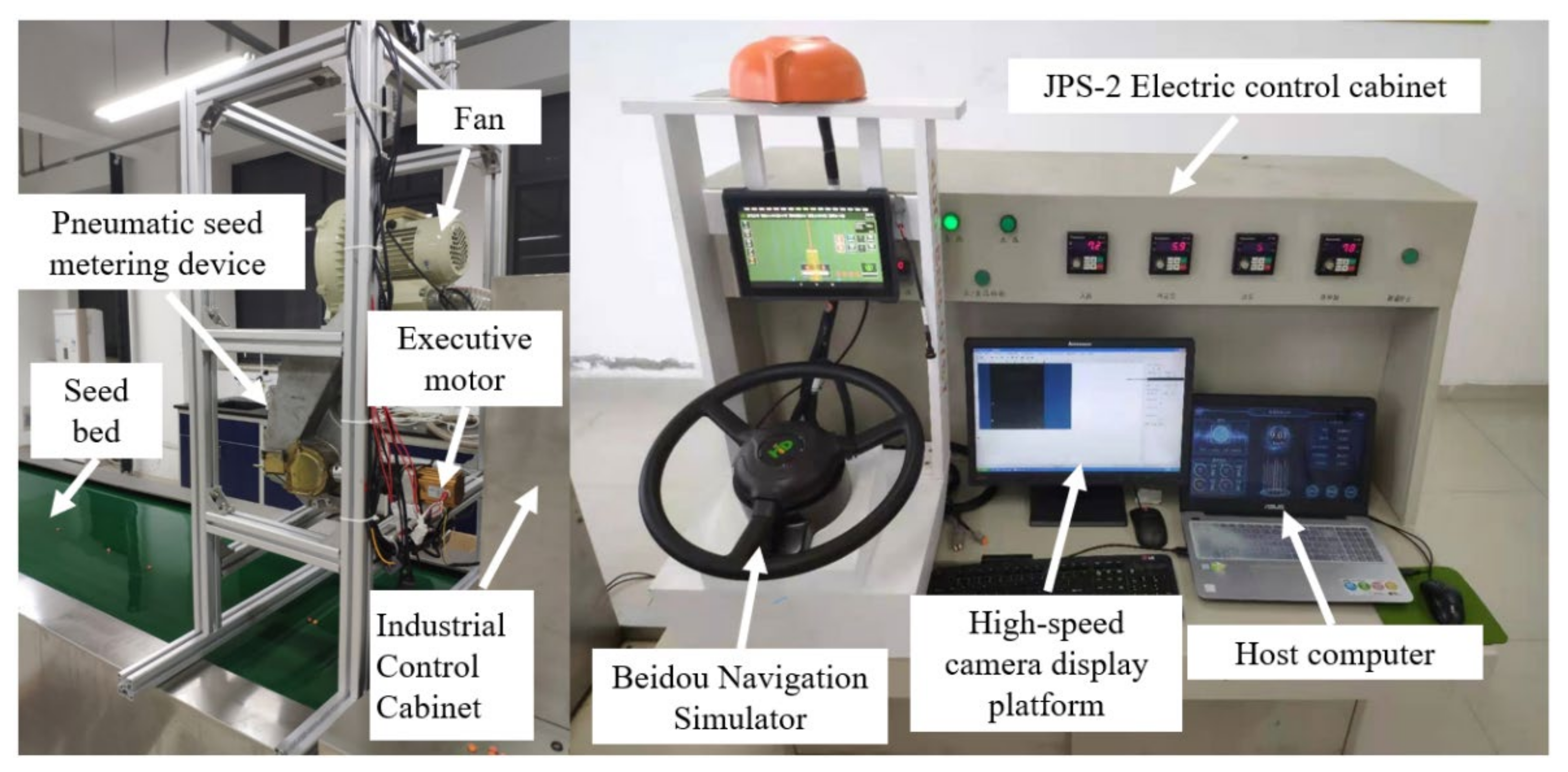
In order to verify whether the EDS can be used for normal sowing and the speed accuracy of the seed-metering motor, a bench test was carried out, and the test was carried out in the electronic control laboratory of the School of Engineering, Anhui Agricultural University. As shown in Figure 7, a test bench was built on the basis of the original JPS-2 electric control cabinet. The test bench uses aluminum alloy as the overall frame, adopts a single seeding motor to simulate the structure of a pneumatic four-channel seeder, and detects the matching degree of the motor and the speed signal. The BDS autopilot simulator is used to simulate the BDS satellite signals under autopilot as the input of the electronic control system to drive the test bench to operate normally. Under different speed inputs, the JPS-2 electric control cabinet movable oiling conveyor belt is used as the seed bed to detect whether the EDS can sow normally. Simulink is used to send PWM to the motor through the communication controller to simulate the variation law of a BDS signal and detect the accuracy of the double closed-loop fuzzy PID control algorithm.

2.3.2. Field Experiments

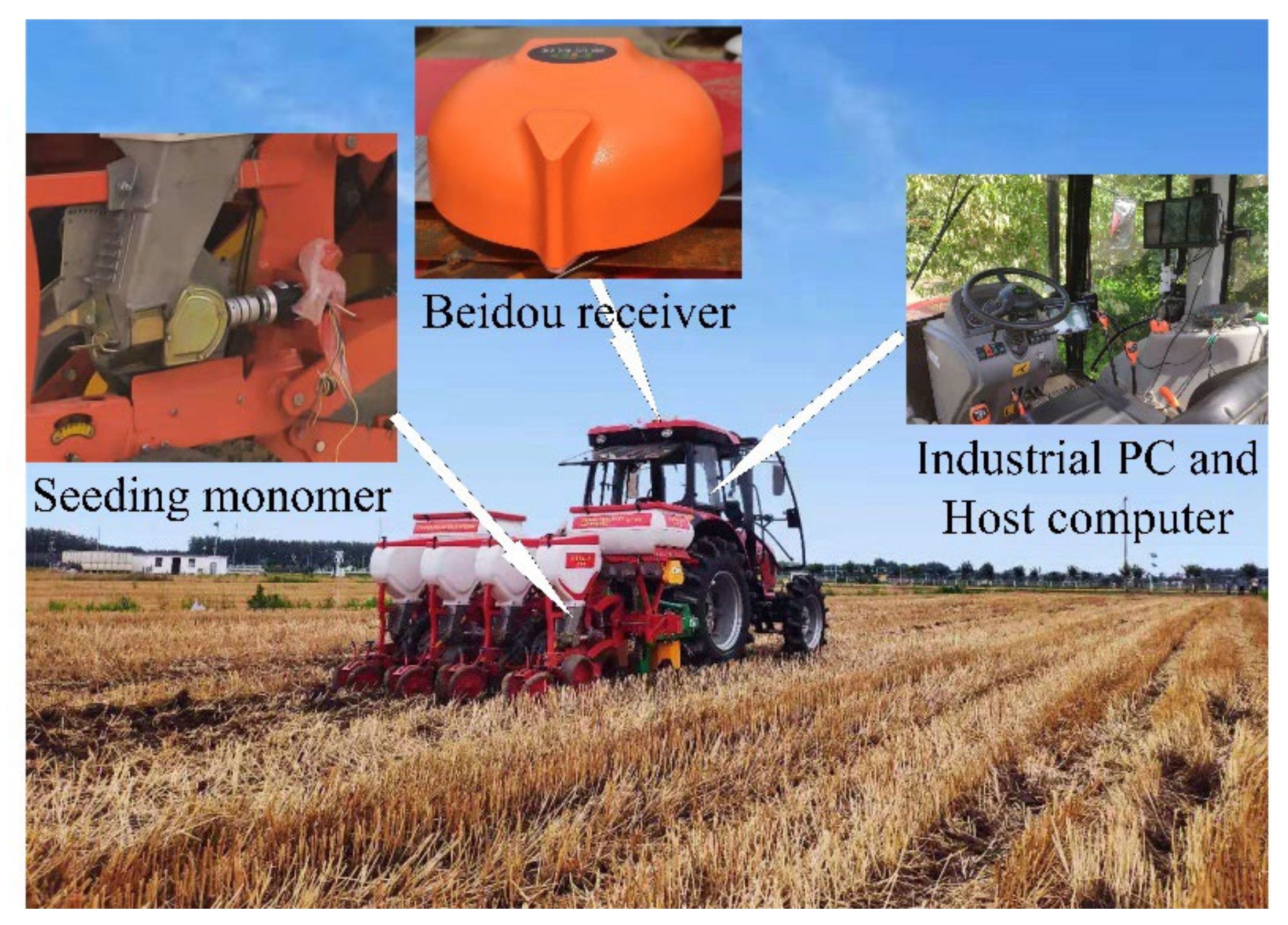
As shown in Figure 8, to test the actual performance of EDS, field experiments were conducted. The experiment was carried out in July 2021 at the Wanbei Experimental Station of Anhui Agricultural University in Suzhou City, Anhui Province. One of the crops in front of the experimental field of the experimental station was wheat without stubble removal treatment. The experiment adopted the 2BMYFQ pneumatic no-tillage seeder, jointly developed by the Anhui Provincial Engineering Laboratory of Intelligent Agricultural Machinery, which realizes the integration of no-tillage seeding and fertilization and is installed on the tractor through a three-point suspension. The tractor adopts Dongfeng DF1004-6, which can provide 100 horsepower and provide traction for the seeder. The tractor with the seeder is a seeding unit on which EDS is loaded. By experimenting with the seeding effect of the seeder, the actual performance of the EDS can be experimented.

3. Results and Discussion

3.1. Bench Test Results and Analysis

3.1.1. Motor Control Algorithm Verification Test

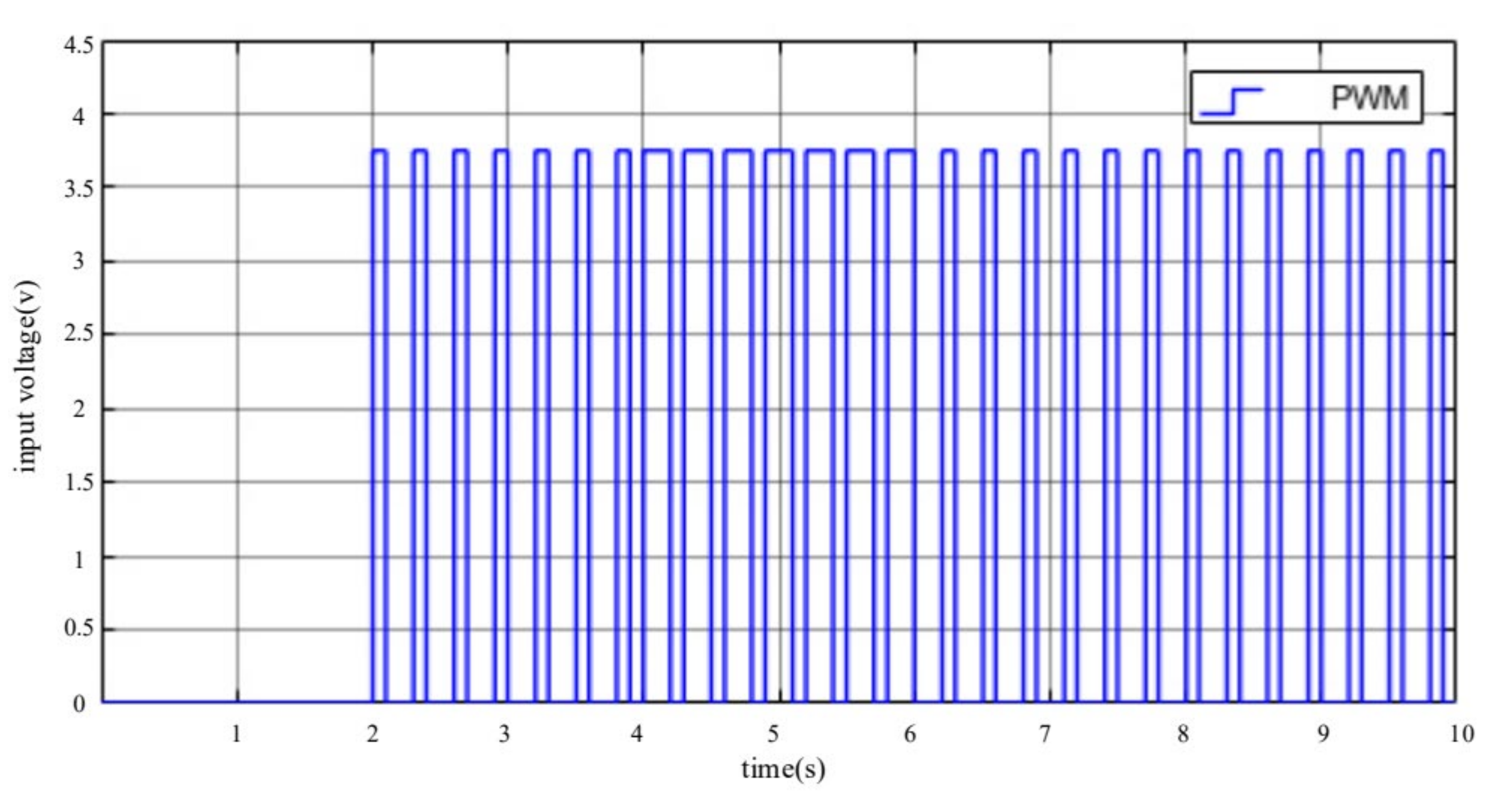
For the motor double closed-loop fuzzy PID control algorithm that has been set, the actual bench is used to simulate the load condition of the field motor. By implanting the double closed-loop fuzzy PID and ordinary PID control algorithms in the system, the response time of the two algorithms in the variable speed of the motor is compared to verify the superiority of the algorithm. As shown in Figure 9, Simulink was used to simulate the PWM waveform as the motor input source, change the motor speed by changing the duty cycle of the PWM wave, and use the interactive tablet to receive the motor speed value, which is used to simulate the acceleration and deceleration conditions of agricultural machinery in the field [31]. In the experiment, the driven speed was increased from 50 r·min−1 to 200 r·min−1 and 200 r·min−1 was reduced to 50 r·min−1 to simulate variable speed seeding when the operation was about to end. First, the motor speed was stabilized at 50·r·min−1 by inputting a PWM with a duty cycle of 20% through Simulink, and then the duty cycle was changed to 80% to increase the motor speed to 200 r·min−1, as shown in Figure 10. It can be seen that based on the double closed-loop fuzzy PID, the control motor increased from 50 r·min−1 to 200 r·min−1 at 4.2 s and tended to be stable. The motor controlled by ordinary PID tended to be stable after 4.7 s, which was 0.5 s longer than that. In the deceleration link, when the duty cycle of the PWM wave became 20%, the speed of the motor controlled by the double closed-loop fuzzy PID was 6.17 s. It was reduced from 200 r·min−1 to 50 r·min−1 and tended to be stable. The ordinary PID algorithm tended to be stable at 6.69 s, and the deceleration was increased by 0.52 s. In summary, the double closed-loop fuzzy PID control algorithm had an average improvement of 0.51 s in motor response time compared with ordinary PID. It can be seen that the double closed-loop fuzzy PID is superior to the ordinary PID in terms of motor control accuracy.

3.1.2. Tests on the Speed Regulation Accuracy of the Dosing Motor of the Seed Metering Device

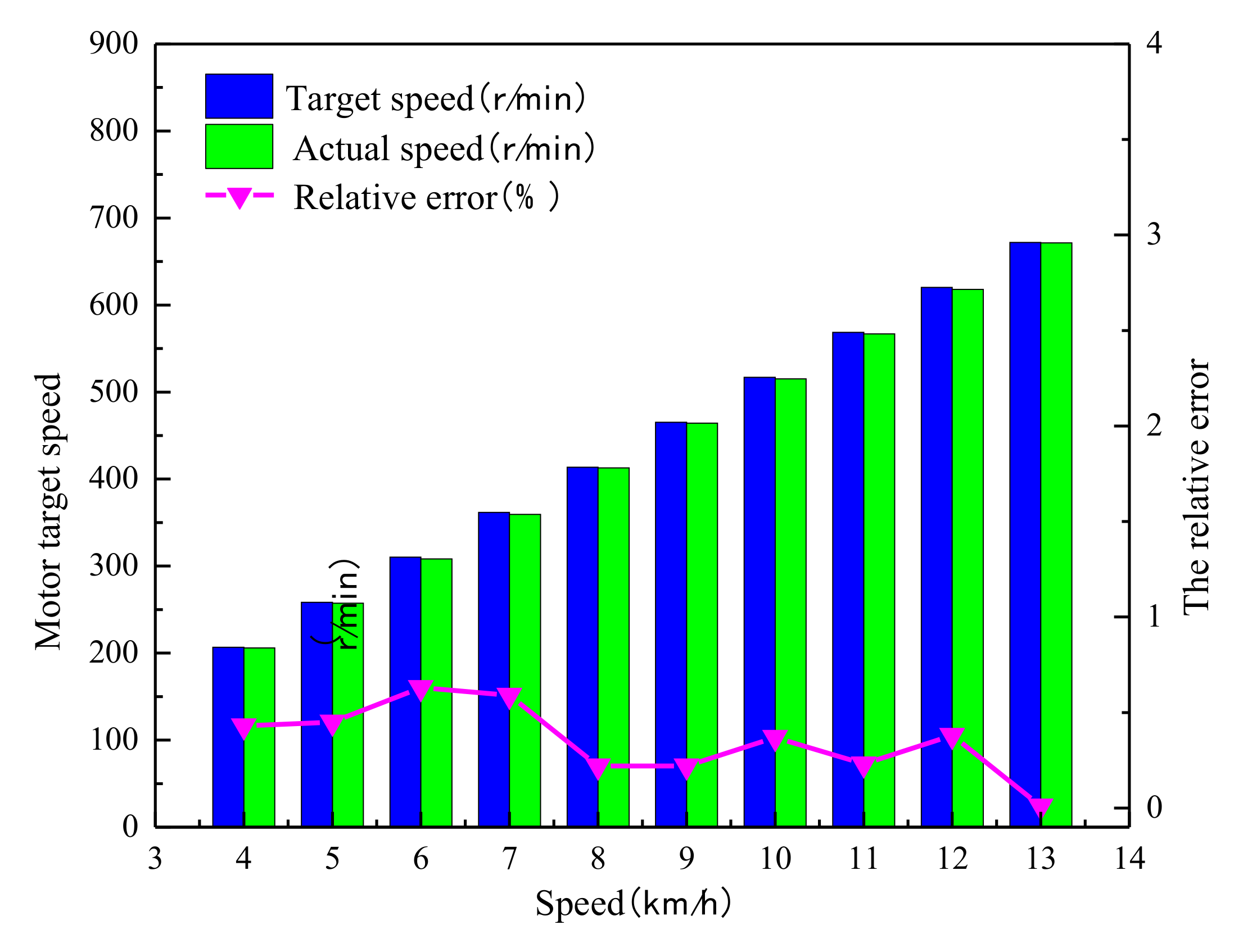
During the seeding process, the control accuracy of the dosing motor of the seed metering device directly affects the seeding effect [11]. In the actual field operation process, the seeding situation is not only affected by the control system, but also affected by the performance of the seed metering device, the soil condition, and the bounce of the seed bed after planting. The bench test is mainly to detect the stability of the controller system to maximize the reduction of the negative impact of the control system on seeding. In the test, the planting spacing was 25 cm, the number of holes in the seeding disc was 26, and the speed was respectively selected from 3 km·h−1 to 13 km·h−1. As shown in Figure 11, the average value of the error between the target value of the motor speed and the actual value was 0.35%, and the speed regulation accuracy was in line with the seeding index. As shown in Figure 12, the seeding effect was good in the bench test.

3.2. Field Experiment Results and Discussion

3.2.1. Field Experiment Results

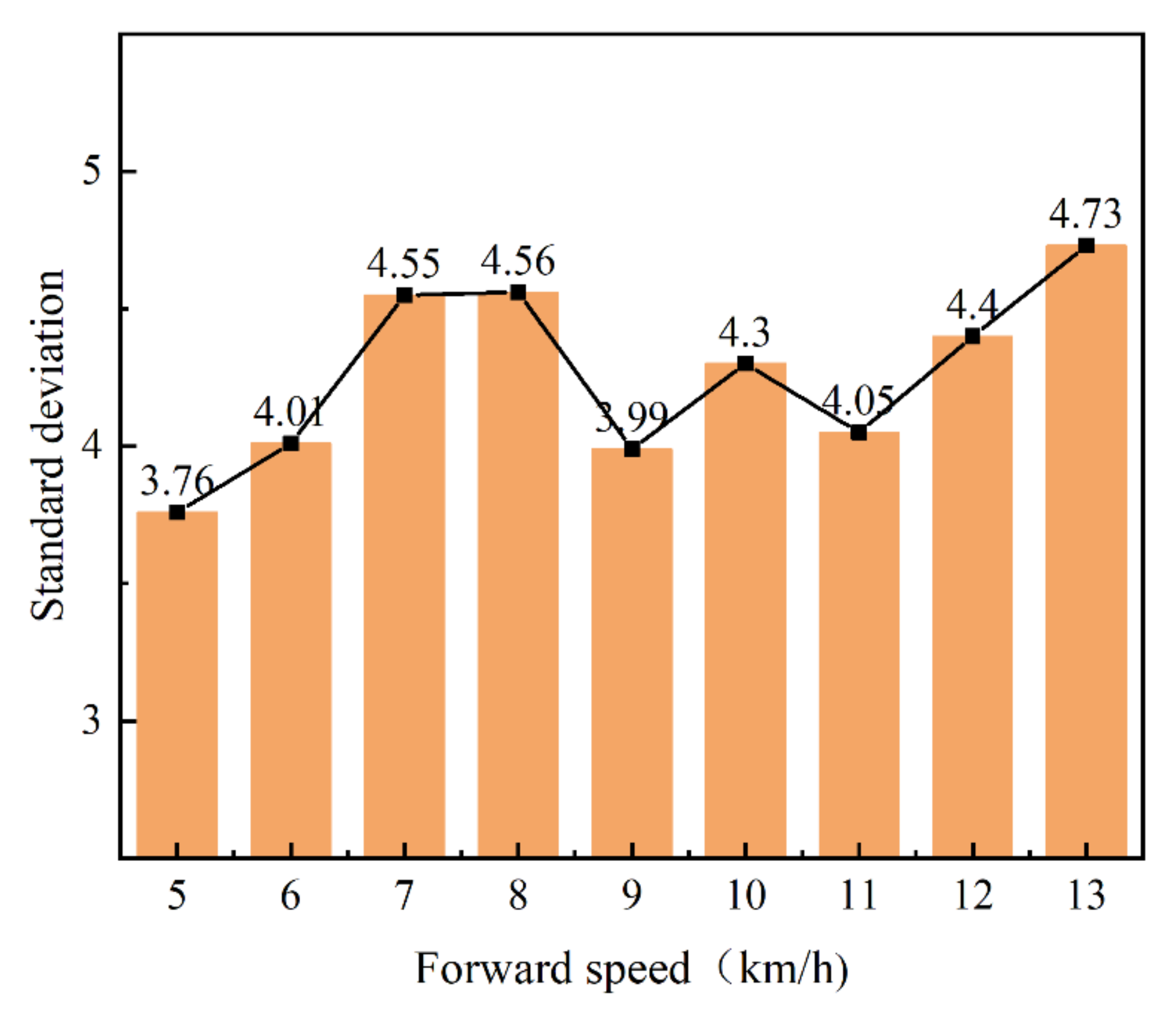
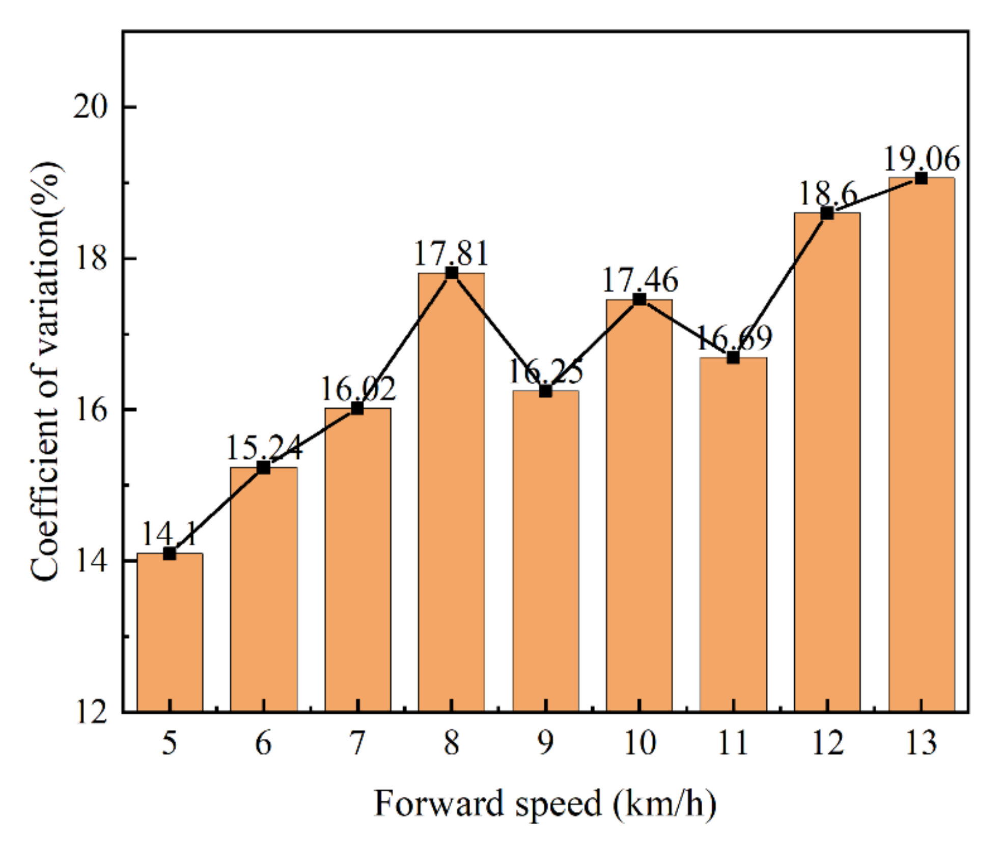
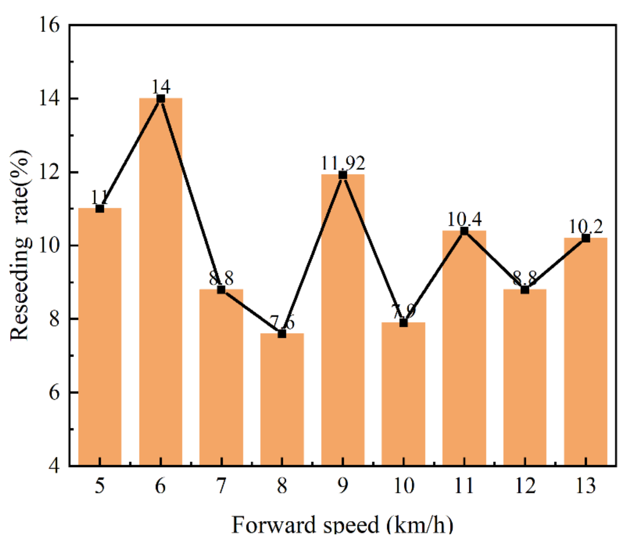
Field experiments and data collection are shown in Figure 13, Figure 14 and Figure 15. The soil had not been changed before the test. The pneumatic active displacement no-tillage planter used was mounted with four seeding units, and the four-way seeding was all driven by this system. The corn was selected from the An-Nong 591 maize seed independently developed by Anhui Agricultural University, and the planting distance was set to 25 cm. The operating speed was from 3 km·h−1 to 13 km·h−1 of which 7 km·h−1, 9 km·h−1, 11 km·h−1, and 13 km·h−1 were selected for high-speed seeding. The planting spacing between the speed switching and the normal planting time were separately measured. The data was collected by the method of measuring the distance between the seedlings in the later stage, and the data processing was based on the GB/T6973-2005 “Single Seed (Precision) Planter Test Method”. The percent of pass (1-standard deviation), coefficient of variation, and reseeding rate were used as indicators to evaluate the performance of the control system. For the collected data, the percent of pass (1-standard deviation) and reseeding rate statistics were calculated, and we obtained the following data analysis charts of percent of pass, coefficient of variation, and reseeding rate.

3.2.2. Discussion

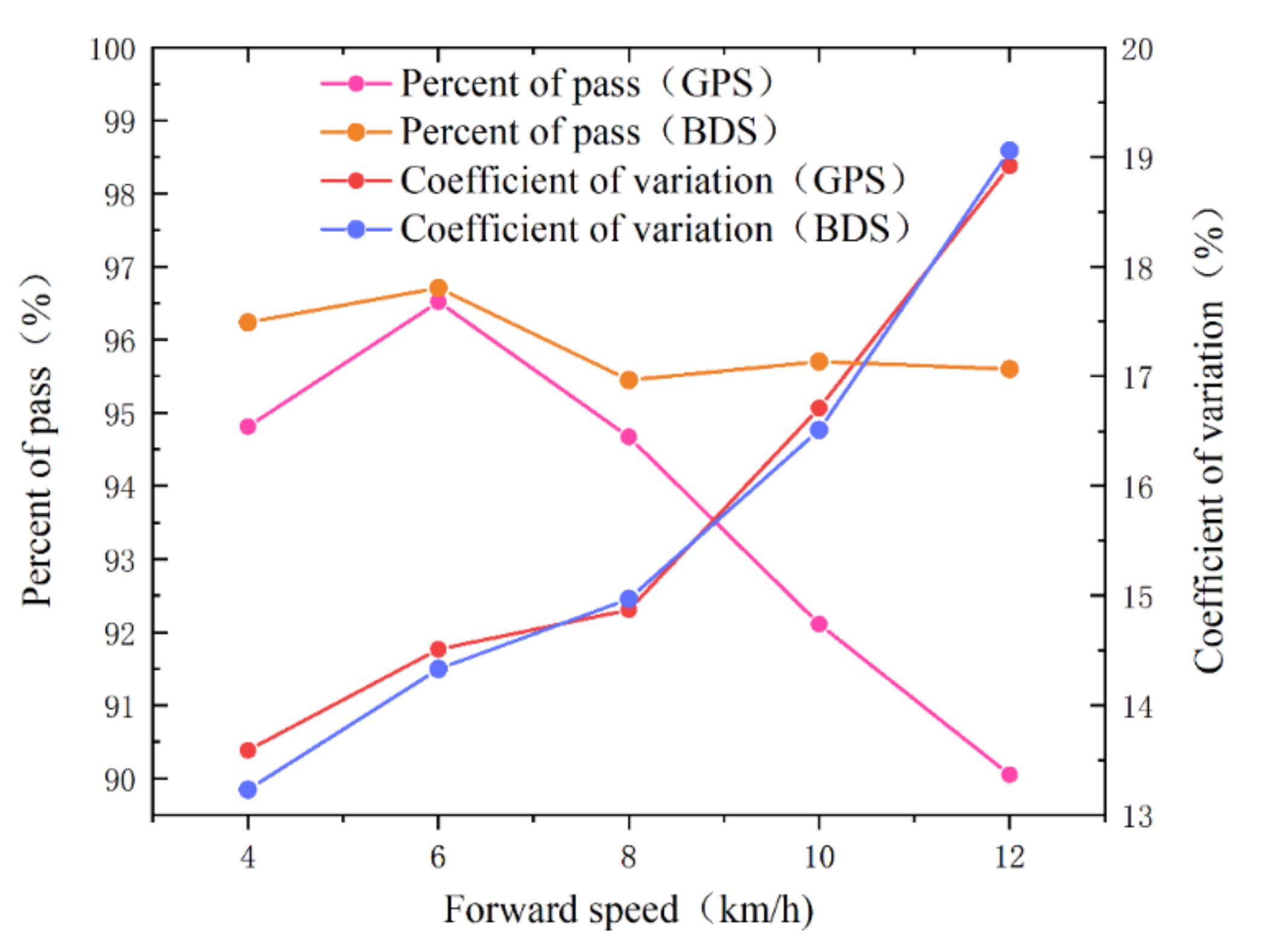
For the quality of sowing, it can be seen from Section 3.2.1 that when the high-speed seeding speed was 8 km·h1, the average seeding percent of pass of this system was 95.44%, the coefficient of variation was 17.81%, and the reseeding rate was 10.80%. The corn planter based on Android and CAN bus developed uses GPS as the input signal of the corn seeding monitoring system [10,23]. The seeding percent of pass at 8 km·h−1 was 94.67%, and the coefficient of variation was 14.87%. However, when the speed of the high-speed precision planter increased to 9 km·h−1 or higher, the requirements for sensor speed acquisition accuracy and system stability were higher. The large error of sensor speed acquisition accuracy and system instability will lead to the reduction of sowing quality. With the increase of speed, due to the stability of the EDS system and the high accuracy of Beidou speed acquisition, when the speed reached 12 km·h−1, the average sowing passing rate of the system was 95.27%, the coefficient of variation was 19.06%, and the re-sowing rate was 10.11%. However, the passing rate of the system developed by using GPS at 12 km·h−1 was 90.05%, and the coefficient of variation was 18.92%. In order to more intuitively understand the influence of the two system speeds on the sowing qualified rate, Figure 16 is drawn. It is not difficult to find that the BDS electronic control system controlled by the double closed-loop fuzzy PID algorithm has the operating conditions for high-speed seeding under automatic driving, which meets the precision seeding standards.
However, technology is a double-edged sword. While enjoying the convenience brought by technological progress, this system will also be affected by the drawbacks of technology. The global positioning system is mainly composed of multiple satellite networks, and satellite signals are affected by many factors when they are sent from space to the earth, such as satellite ephemeris error, satellite clock error, cloud thickness, receiver clock error, atmospheric refraction error and the multipath effect of the signal, etc. [32,33] This system mainly uses the BDS to issue real-time longitude and latitude signals as the system’s working input source, so the signals received by the BDS signal receiver will be unstable under the influence of many factors. It will cause a gap between the measured speed and the actual speed. The system execution motor will stop and rotate rapidly as the signal is unstable, which will lead to problems, such as miss-seeding and reseeding. Signal instability is a major problem faced by the current intelligent seeding system that uses the global positioning system as the signal input source. The next step in the research of this system will focus on the problem of satellite signal instability. It is hoped that the combination of software and hardware is used to transform the traditional single satellite navigation signal into a multi-sensor plus satellite-integrated navigation method for signal complementary combination input, so as to solve system instability caused by the instability of the satellite signal. This research is a subject to further study.

4. Conclusions

An electronic control system for high-speed precision seeding of corn under the condition of automatic driving based on BDS has been established. The main body is composed of an intelligent communication controller, an interactive tablet, and a four-way drive unit. The distributed CAN bus is used as the connection of the various parts of the system, which are mainly between the BDS and the industrial computerand between the industrial computer and the four-way drive unit. Conforming to the development direction of agricultural and rural modernization, it has achieved automation, intelligence, and humanization. The combination of automatic driving and electronic control seeding has been realized, which reduces the labor burden to a certain extent. The position and speed double closed-loops are used to optimize the speed accuracy of the motor, and a self-tuning fuzzy PID control algorithm have been established. In the bench test, the response time of the motor was measured by changing the input speed of the system to simulate the conditions of acceleration and deceleration and gear change in the field. Compared with the traditional single closed-loop PID, the response time was shortened by 0.51 s. Compared with the target speed, the average precision error was 0.35%, which effectively shortens the response time of the motor, keeps the actual speed of the motor basically consistent with the theoretical speed, and minimizes the system error caused by the control accuracy. In the field experiment, when the speed was 5 km·h−1, the average seeding percent of pass (standard deviation) of this system was 96.24%, the coefficient of variation was 15.13%, and the reseeding rate was 11.12%. When the speed was increased to 9 km·h−1 or more, the stability of the system was required to be higher, and system instability would occur. However, as the speed increased, due to the stability of the system, when the speed reached 13 km·h−1, the average seeding percent of pass (standard deviation) of the system was 95.27%, the coefficient of variation was 19.06%, and the reseeding rate was 10.11%. It is not difficult to find that the BDS electronic control system, which is reliably regulated by the self-tuning double closed-loop fuzzy PID algorithm, has the operating conditions under high-speed seeding and meets the operating standards.

Author Contributions

Conceptualization, K.W.; methodology, K.W.; software, K.W.; validation, K.W.; formal analysis, Y.Z.; investigation, M.W.; resources, K.W.; data curation, K.W.; writing—original draft preparation, K.W.; writing—review and editing, L.C.; visualization, C.Z.; supervision, L.C.; project administration, W.W.; funding acquisition, W.W. All authors have read and agreed to the published version of the manuscript.

Funding

This work was Supported by the National Natural Science Foundation of China (NO. 52005008), Natural Science Foundation of Anhui Province (NO. 2008085QE217), and the Natural Science Research Project of Higher Education Institutions (NO. KJ2021A0158).

Institutional Review Board Statement

Not applicable.

Informed Consent Statement

Not applicable.

Data Availability Statement

The data used in this study is self-tested and self-collected. As the control method designed in this paper is still being further improved, data cannot be shared at present.

Conflicts of Interest

The authors declare no conflict of interest.

References

  1. Wu, C.C.; Fang, X.M. Development of precision service system for intelligent agriculture field crop production based on BeiDou system. Smart Agric. 2019, 1, 83–90. [Google Scholar]
  2. Li, C.L.; Jiang, Z.Y. Design of Urban vehicle dynamic and real-Time navigation system based on WSNs, GPS, and GPRS techniques. Adv. Mater. Res. 2013, 2584, 765–767. [Google Scholar] [CrossRef]
  3. Lee, D.-H.; Kim, H.-J.; Park, J.-H. UAV, a farm map, and machine learning technology convergence classification method of a corn cultivation area. Agronomy 2021, 11, 1554. [Google Scholar] [CrossRef]
  4. May, S.; Kocabiyik, H. Design and development of an electronic drive and control system for micro-granular fertilizer metering unit. Comput. Electr. Agric. 2019, 162, 921–930. [Google Scholar] [CrossRef]
  5. He, X.; Ding, Y.; Zhang, D. Development of a variable-rate seeding control system for corn planters Part II: Field performance. Comput. Electr. Agric. 2019, 162, 309–317. [Google Scholar] [CrossRef]
  6. Devin, L.; Mangus; Ajay, S.; Daniel, F.; Ryan, S.; Terry, G. Research on the planting drive system based on a tractor front-wheel speed. Comput. Electr. Agric. 2017, 142, 314–325. [Google Scholar]
  7. Quan, L.Z.; Jiang, W.; Li, H.L.; Li, H.D.; Wang, Q.; Chen, L.Q. Intelligent intra-row robotic weeding system combining deep learning technology with a targeted weeding mode. Biosyst. Eng. 2022, 48, 51–59. [Google Scholar] [CrossRef]
  8. Zhang, C.L.; Wu, R.; Chen, L.Q. Design and test of electronic control seeding system for maize. Trans. Chin. Soc. Agric. Mach. 2017, 48, 51–59. [Google Scholar]
  9. Iacomi, C.; Popescu, O. A new concept for seed precision planting. Agric. Agric. Sci. Proc. 2015, 6, 38–43. [Google Scholar] [CrossRef] [Green Version]
  10. Ding, Y.Q.; Yang, L.; Zhang, D.X.; Cui, T. Novel low-cost control system for large high-speed corn precision planters. Int. J. Agric. Biol. Eng. 2021, 14, 151–158. [Google Scholar] [CrossRef]
  11. Yang, S.; Wang, X.; Gao, Y.Y.; Zhai, C.Y.; Zhang, X.G.; Zhao, C.J. Investigation on motor-driving maize precision seed meter system supporting on-site calibration of rotate speed of seed plate. Trans. Chin. Soc. Agric. Mach. 2020, 51, 47–55. [Google Scholar]
  12. Xie, C.J.; Zhang, D.X.; Yang, L. Remote monitoring system for maize seeding parameters based on android and wireless communication. Int. J. Agric. Biol. Eng. 2020, 13, 159–165. [Google Scholar] [CrossRef]
  13. Chen, L.Q.; Xu, Z.Z.; Xie, B.B.; Liu, L.; Xu, M.; Zheng, Q. Design and test of electronic control system for unmanned drive sprayer. Trans. Chin. Soc. Agric. Mach. 2019, 50, 122–128. [Google Scholar]
  14. Ding, Y.C.; Liu, W.P.; Dong, W.J.; Chen, L.Y.; Liu, X.D.; Jin, W. Design and experiment of seed metering device for rapeseed based on seeding frequency feedback. Trans. Chin. Soc. Agric. Mach. 2021, 52, 73–82. [Google Scholar]
  15. Zhao, X.; Chen, L.; Gao, Y. Optimization method for accurate positioning seeding based on sowing decision. Int. J. Agric. Biol. Eng. 2021, 14, 151–158. [Google Scholar] [CrossRef]
  16. Chen, L.Q.; Xie, B.B.; Li, Z.D.; Yang, L.; Chen, Y.X. Design of control system of maize precision seeding based on double closed loop PID fuzzy algorithm. Trans. Chin. Soc. Agric. Eng. 2018, 34, 33–41. [Google Scholar]
  17. Li, J.L.; Wang, B.; Wang, A.B.; Zhu, E.H.; Yuan, H.Y. BDS/GPS dual-frequency carrier-phase single point positioning model and accuracy analysis. Navig. Position. Timing 2021, 8, 120–128. [Google Scholar]
  18. Liu, Y.C. High-precision positioning analysis of BDS observation data. Share Geospat. Inf. 2021, 19, 46–48. [Google Scholar]
  19. Singh, T.P.; Mane, D.M. Development and laboratory performance of an electronically controlled metering mechanism for okra seed. Agric. Mech. Asia Afr. Lat. Am. 2011, 42, 63–69. [Google Scholar]
  20. Wang, G.; Sun, W.; Zhang, H.; Liu, X.; Zhu, L. Research on a kind of seeding-monitoring and compensating control system for potato planter without additional seed-metering channel. Comput. Electr. Agric. 2020, 177, 105681. [Google Scholar] [CrossRef]
  21. Zhao, L.; Han, Z.; Yang, J.; Hua, Q. Single seed precise sowing of maize using computer simulation. PLoS ONE 2018, 13, e0193750. [Google Scholar] [CrossRef] [PubMed] [Green Version]
  22. He, X.; Cui, T.; Zhang, D. Development of an electric-driven control system for a precision planter based on a closed-loop PID algorithm. Comput. Electr. Agric. 2017, 136, 184–192. [Google Scholar] [CrossRef]
  23. Ding, Y.Q.; Liu, Y.W.; Yang, L.; Zhang, D.X.; Cui, T.; Zhong, X.J. Monitoring system of maize precision planter based on android and CAN Bus. Trans. Chin. Soc. Agric. Mach. 2019, 50, 33–41. [Google Scholar]
  24. Chen, C.; Lv, J.; Song, G.; Liu, H. Adaptive fuzzy sliding mode control algorithm based on input-output linearization for vehicle’s lateral control. In Proceedings of the 2016 IEEE Chinese Guidance, Navigation and Control Conference (CGNCC), Nanjing, China, 12–14 August 2016; IEEE: Piscataway Township, NJ, USA, 2016. [Google Scholar]
  25. Stoll, J.T.; Schanz, K.; Pott, A. Mechatronic Control System for a Compliant and Precise Pneumatic Rotary Drive Unit. Actuators 2020, 9, 1. [Google Scholar] [CrossRef] [Green Version]
  26. Nguyen, H.P.; Nguyen, X.B.; Bui, T.T.; Ueno, S.; Nguyen, Q.D. Analysis and Control of Slotless Self-Bearing Motor. Actuators 2019, 8, 57. [Google Scholar] [CrossRef] [Green Version]
  27. Vinosh, M.; Kumar, S.S.; Nithish, D.; Naveen, G. Development of tray type nursery seeding equipment. Mater. Today Proc. 2021, 37, 3209–3212. [Google Scholar] [CrossRef]
  28. Lou, S.; He, J.; Lu, C.; Liu, P.; Li, H.; Zhang, Z. A Tillage Depth Monitoring and Control System for the Independent Adjustment of Each Subsoiling Shovel. Actuators 2021, 10, 250. [Google Scholar] [CrossRef]
  29. Yang, Y.; Li, Y.K.; Wen, X.; Zhang, G.; Ma, Q.L.; Cheng, S.K.; Qi, J.; Xu, L.Y.; Chen, L.Q.; Popescu, O. An optimal goal point determination algorithm for automatic navigation of agricultural machinery: Improving the tracking accuracy of the Pure Pursuit algorithm. Comput. Electr. Agric. 2022, 194, 106760. [Google Scholar] [CrossRef]
  30. Darwin, B.; Dharmaraj, P.; Prince, S.; Popescu, D.E.; Hemanth, D.J. Recognition of Bloom/Yield in Crop Images Using Deep Learning Models for Smart Agriculture: A Review. Agronomy 2021, 11, 646. [Google Scholar] [CrossRef]
  31. Folprecht, M.; Cervinka, D.; Prochazka, P. Compact High-Voltage AC Generator with Pulse Transformer for High-Frequency Irreversible Electroporation (H-FIRE). Electronics 2021, 10, 2898. [Google Scholar] [CrossRef]
  32. Cay, A.; Kocabiyik, H.; May, S. Development of an electro-mechanic control system for seed-metering unit of single seed corn planters Part I: Design and laboratory simulation. Comput. Electr. Agric. 2018, 144, 71–79. [Google Scholar] [CrossRef]
  33. Cay, A.; Kocabiyik, H.; May, S. Development of an electro-mechanic control system for seed-metering unit of single seed corn planters Part II: Field performance. Comput. Electr. Agric. 2018, 145, 11–17. [Google Scholar] [CrossRef]
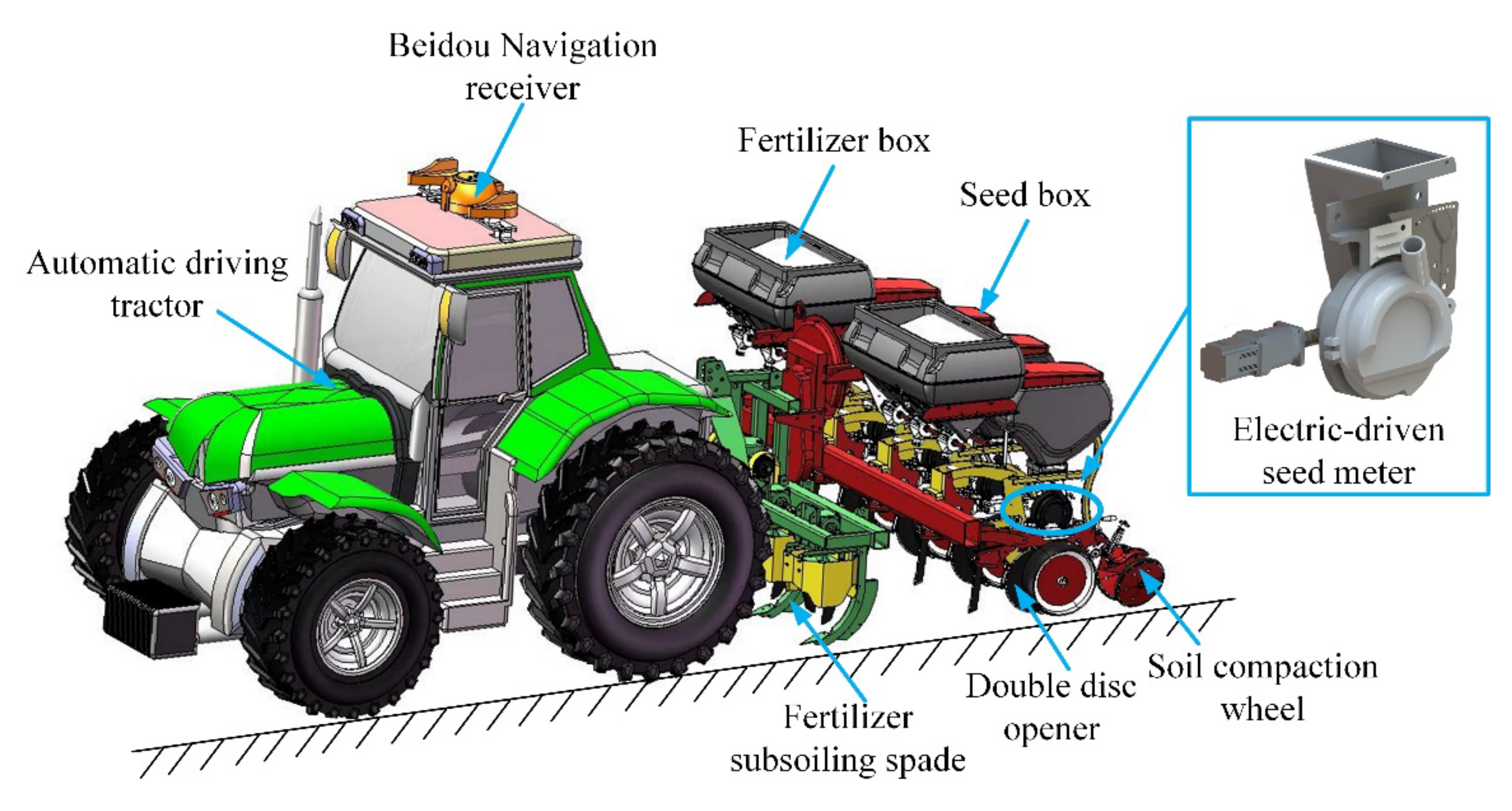
Figure 1. Overall structure of seeding unit.
Agronomy 12 00945 g001
Figure 2. Components of electric-driven seeding control system.
Agronomy 12 00945 g002
Figure 3. Schematic of the EDS control system.
Agronomy 12 00945 g003
Figure 4. Analytic map of latitude and longitude.
Agronomy 12 00945 g004
Figure 5. Double closed-loop speed control structure.
Agronomy 12 00945 g005
Figure 6. Block diagram of self-tuning double closed-loop fuzzy PID control strategy.
Agronomy 12 00945 g006
Figure 7. Test bench structure drawing.
Agronomy 12 00945 g007
Figure 8. The field experiment.
Agronomy 12 00945 g008
Figure 9. PWM input waveform diagram.
Agronomy 12 00945 g009
Figure 10. Comparison of response curves of motor control algorithms.
Agronomy 12 00945 g010
Figure 11. Speed accuracy detection.
Agronomy 12 00945 g011
Figure 12. Sowing effect of bench test.
Agronomy 12 00945 g012
Figure 13. Standard deviation (percent of pass).
Agronomy 12 00945 g013
Figure 14. Coefficient of variation.
Agronomy 12 00945 g014
Figure 15. Reseeding rate.
Agronomy 12 00945 g015
Figure 16. The influence of different speeds on the sowing qualification rate and the coefficient of variation.
Agronomy 12 00945 g016
Table 1. The fuzzy control rules.
Ec
ENBNSZOPSPB
Δ K p Δ K i Δ K d Δ K p Δ K i Δ K d Δ K p Δ K i Δ K d Δ K p Δ K i Δ K d Δ K p Δ K i Δ K d
NBPB PB NBPB PS NBPB PS NSZO NB NSZO NS NB
NSPB PS NBPB PS NSPS ZO ZOZO NS NSNS NS NB
ZOPS ZO NSPS ZO ZOZO ZO PSNS ZO ZONS ZO ZO
PSPS ZO ZOZO NS PSNS ZO PSNB PS PSNB PS ZO
PBZO NS ZOZO NB PSNB NS PBNB PS PSNB PB ZO
Publisher’s Note: MDPI stays neutral with regard to jurisdictional claims in published maps and institutional affiliations.