Abstract
The yield and quality of rice are closely related to field management. The automatic identification of field abnormalities, such as diseases and pests, based on computer vision currently mainly relies on high spatial resolution (HSR) images obtained through manual field inspection. In order to achieve automatic and efficient acquisition of HSR images, based on the capability of high-throughput field inspection of UAV remote sensing and combining the advantages of high-flying efficiency and low-flying resolution, this paper proposes a method of “far-view and close-look” autonomous field inspection by unmanned aerial vehicle (UAV) to acquire HSR images of abnormal areas in the rice canopy. First, the UAV equipped with a multispectral camera flies high to scan the whole field efficiently and obtain multispectral images. Secondly, abnormal areas (namely areas with poor growth) are identified from the multispectral images, and then the geographical locations of identified areas are positioned with a single-image method instead of the most used method of reconstruction, sacrificing part of positioning accuracy for efficiency. Finally, the optimal path for traversing abnormal areas is planned through the nearest-neighbor algorithm, and then the UAV equipped with a visible light camera flies low to capture HSR images of abnormal areas along the planned path, thereby acquiring the “close-look” features of the rice canopy. The experimental results demonstrate that the proposed method can identify abnormal areas, including diseases and pests, lack of seedlings, lodging, etc. The average absolute error (AAE) of single-image positioning is 13.2 cm, which can meet the accuracy requirements of the application in this paper. Additionally, the efficiency is greatly improved compared to reconstruction positioning. The ground sampling distance (GSD) of the acquired HSR image can reach 0.027 cm/pixel, or even smaller, which can meet the resolution requirements of even leaf-scale deep-learning classification. The HSR image can provide high-quality data for subsequent automatic identification of field abnormalities such as diseases and pests, thereby offering technical support for the realization of the UAV-based automatic rice field inspection system. The proposed method can also provide references for the automatic field management of other crops, such as wheat.
1. Introduction
Rice is one of the most important food crops in China and even in the world. Its production affects the food security of the country [1,2,3], and the yield and quality of rice are closely related to field management [4,5]. In recent years, in order to improve the efficiency and quality of field management, researchers in the agricultural field have developed various types of automatic equipment (such as self-driving agricultural machinery, agricultural UAVs, etc.) to perform management actions such as fertilization and pesticide application [6,7,8]. However, field management decisions are currently mainly made through manual field inspections. In order to detect diseases and pests, water and fertilizer management problems, and other issues in time, agricultural experts regularly observe the rice fields according to the established route. Generally, they first look at the whole from a distance, find abnormalities, then look closer at the details and record. Manual field inspection is not only labor-intensive and inefficient but also depends on experience and has high subjectivity.
With the mature development of UAV and sensor technology and the popularization of agricultural UAVs, UAVs can be equipped with various sensors for multi-modal and high-throughput field inspection [8,9], and those equipped with multispectral cameras are now especially widely used to achieve precision agriculture [10,11,12,13]. Compared with manual field inspection, the advantages of UAV field inspection are shown in Table 1. In addition, the development of artificial intelligence technology provides a “brain” for field management decision making [14], among which the development of computer vision technology provides technical means for automatically identifying abnormal conditions in the field, such as diseases and pests [15,16,17,18,19,20,21,22].

Table 1.
Comparison between manual field inspection and UAV field inspection.
Su et al. [23] proposed a method for identifying wheat yellow rust by learning from multispectral UAV imagery, and the experimental results indicated that (1) good classification performance (with an average precision, recall, and accuracy of 89.2%, 89.4%, and 89.3%) was achieved; (2) the top three vegetation indices (VIs) for separating healthy and yellow rust infected wheat plants were the Ratio Vegetation Index (RVI), Normalized Difference Vegetation Index (NDVI), and Optimized Soil-Adjusted Vegetation Index (OSAVI), while the top two spectral bands were Near-Infrared (NIR) and Red. A high-throughput method for above-ground estimation of biomass in rice using multispectral imagery captured at different scales of the crop was proposed by Devia et al. [24], in which seven VIs were calculated to model the relationship, and the results have shown that the proposed approach was able to estimate the biomass of large areas of the crop with an average correlation of 0.76. Kim et al. [25] used the VI extracted from UAV multispectral imagery for crop damage assessment after chemical exposure, and the results demonstrated that the NDVI was capable of reflecting the plant response to chemical exposure and was feasible as an alternative for crop monitoring, damage assessment after chemical exposure, and yield prediction. Wang et al. [12] studied the estimation of the nitrogen status of paddy rice at the vegetative phase using UAV-based multispectral imagery and found an index-based model which correlated well with the N-index values. Many studies have shown that the VI based on UAV multispectral remote sensing images can be used to monitor the growth status of rice and other crops [10,11,12,13,23,24,25,26]. However, there is a contradiction in the low-altitude remote sensing of UAVs: by flying high, the efficiency is high, but the image spatial resolution is low; by flying low, the image spatial resolution is high, but the efficiency is low. In addition, multispectral remote sensing has the problem of the same spectrum and foreign objects (namely different abnormalities with the same appearance in remote sensing images), which makes it difficult to discriminate different abnormalities [26]. Therefore, exploring how to efficiently inspect the field to acquire rich and useful data for determining whether crop growth exhibits abnormal conditions and even identifying specific types of abnormalities is the objective of this study.
State-of-the-art large-scale deep learning frameworks have been tested by Rahman et al. [15] to investigate the effectiveness in rice plant disease and pest identification from images collected from real-life environments, while they proposed a novel two-stage light-weight Convolutional Neural Network (CNN) highly effective for mobile device based rice plant disease and pest detection, which could be an effective tool for farmers in a remote environment. Chen et al. [16] have combined the DenseNet and inception module to achieve an average predicting accuracy of no less than 94.07% in the public dataset. Shrivastava et al. [17] used VGG16 for classifying the diseases from the 1216 images of seven classes and achieved 93.11% accuracy. Patil et al. [18] proposed a novel multi-modal data fusion framework to diagnose rice diseases using the numerical features extracted from agro-meteorological data collected from sensors and the visual features extracted from the captured rice images, and the experimental results demonstrated that the proposed framework outperformed the outcome of unimodal frameworks. For rapid detection of nutrient stress, Anami et al. [19] used VGG16 for different biotic and abiotic stress detection in rice, while Wang et al. [20] combined CNN and reinforcement learning for NPK detection. Dey et al. [21] have evaluated the performance of CNN-based pre-trained models for the efficient detection of biotic stressed rice leaves caused by two fungal diseases, one insect pest, and three abiotic stressed leaves caused by NPK deficiency by using both public and field data collected, respectively, from laboratory and real field conditions. Hu et al. [22] proposed a rice pest identification method based on a CNN and migration learning, which effectively improved the recognition accuracy of pest images and significantly reduced the number of model parameters. From the above literature, it can be seen that significant achievements have been made in the automatic identification of field abnormalities, such as diseases and pests, based on visible light images [15,16,17,18,19,20,21,22,26]. However, the training and application of the recognition model all rely on HSR images, currently mainly obtained manually, which is not only inefficient but also labor-intensive. Therefore, the automatic acquisition of HSR images is also the starting point of this research.
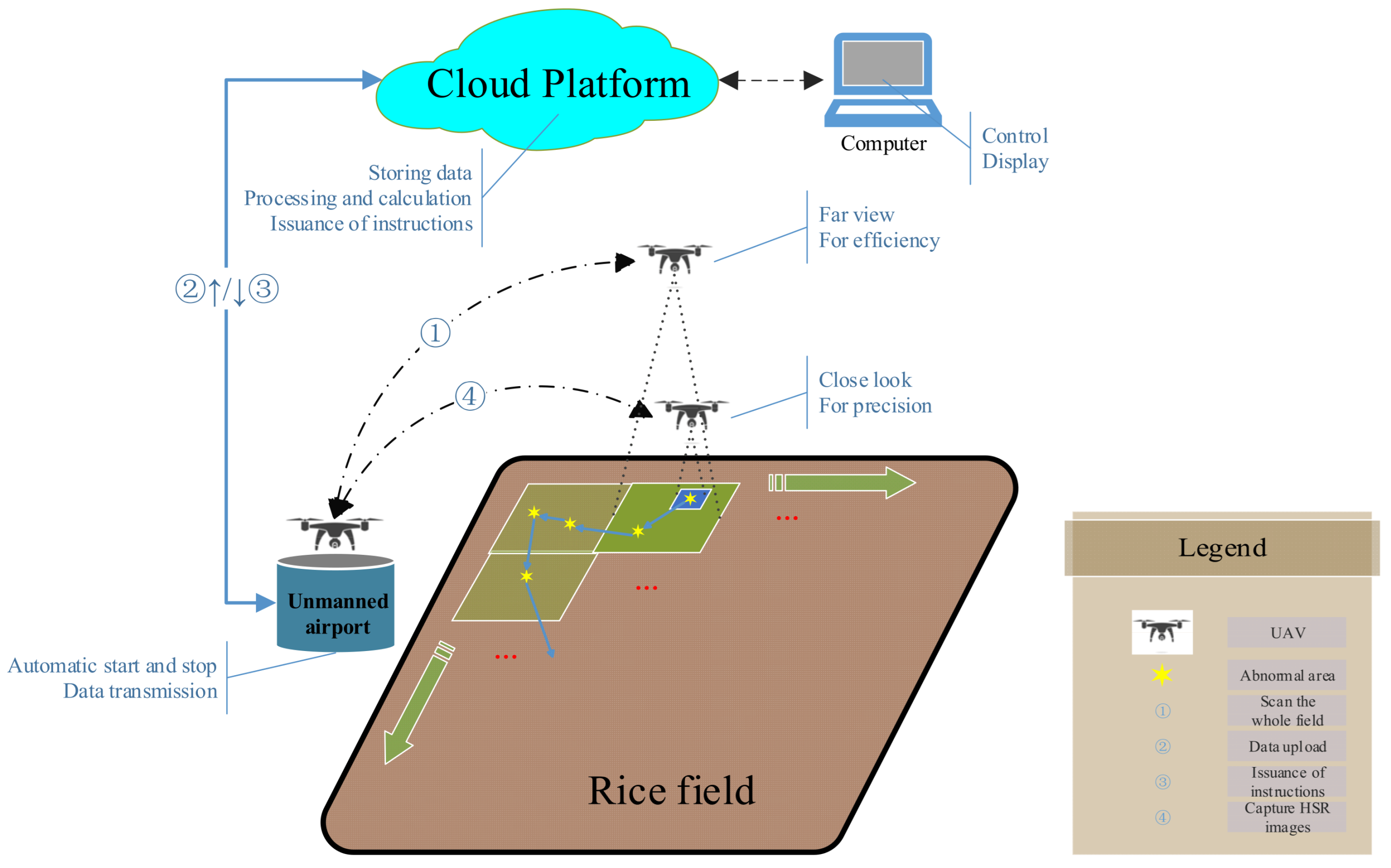
In general, UAVs have been widely used in the field of agriculture, and UAVs equipped with multispectral cameras have greatly improved the efficiency of field inspections. However, if UAVs fly high, the image spatial resolution will be low, and if UAVs fly low, the efficiency will be low. In addition, automatic recognition relies on HSR images. If we can simulate the method of manual field inspection, “first view far then look close”, and combine the advantages of high-flying and low-flying, or specifically, first preliminarily identify abnormal areas efficiently at a high altitude and then accurately identify abnormal areas at a low altitude, both efficiency and precision can be achieved. Based on the above idea, we propose an automatic field inspection system, as shown in Figure 1. Based on this system, a method for acquiring HSR images of rice canopy abnormal areas by autonomous UAV field inspection is proposed in this paper. First, the UAV equipped with a multispectral camera flies high to scan the whole field efficiently and obtain multispectral images. Secondly, abnormal areas (namely areas with poor growth) are identified from the multispectral images, and then the geographical locations of identified abnormal areas are positioned with a single-image method instead of the most used method of reconstruction, sacrificing part of positioning accuracy for efficiency. Finally, the optimal path for traversing abnormal areas is planned through the nearest-neighbor algorithm, and then the UAV equipped with a visible light camera flies low to capture HSR images of abnormal areas along the planned path.
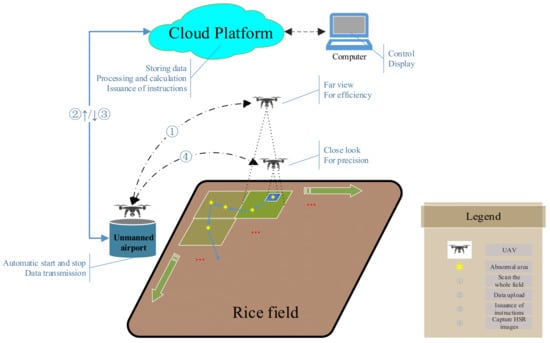
Figure 1.
Automatic field inspection system.
2. Materials and Methods
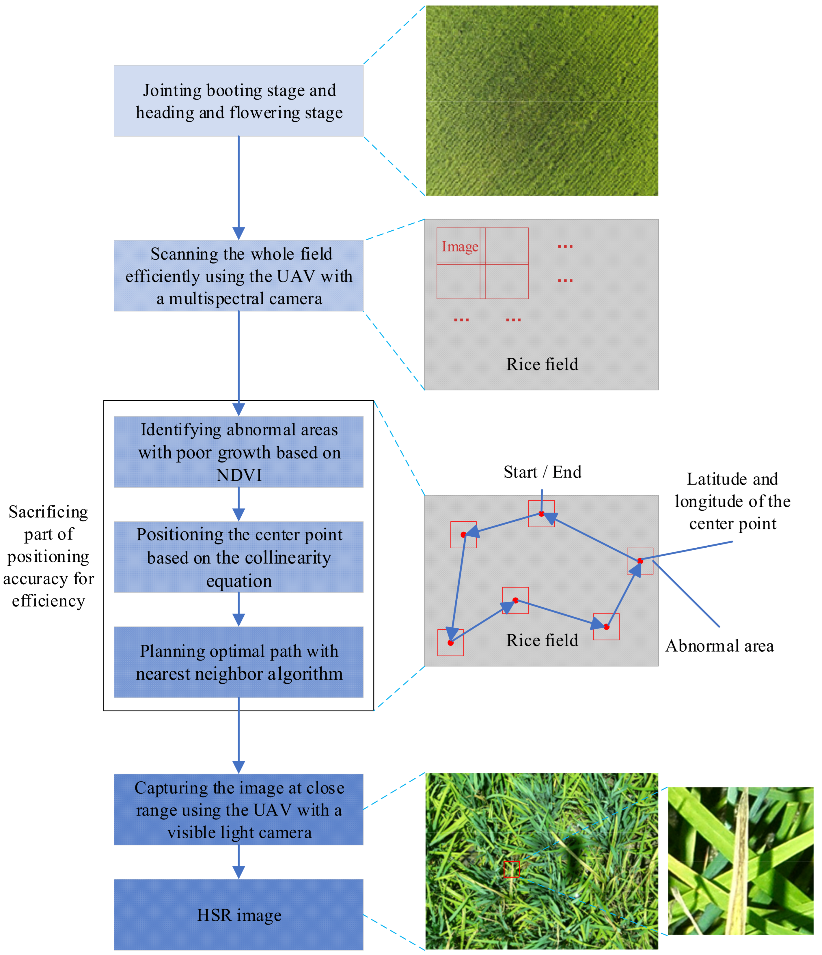
The natural rice field environment is very complex, and it is necessary to reduce background disturbances such as soil. In addition, the jointing booting stage and heading and flowering stage are the main control periods for rice diseases and pests [27], and VIs during this period are also relatively stable [28]. Therefore, the method in this paper is mainly applied to the jointing booting stage and heading and flowering stage of rice. According to previous research results, the NDVI has a strong linear or exponential relationship with the leaf area index (LAI), biomass, leaf chlorophyll content, etc. [25,29], which means the NDVI can be used to judge the growth status of crops. The main processing flow of the method in this paper is shown in Figure 2: far view with multispectral UAV; identification of abnormal areas; positioning of the center point of the abnormal area; path planning; and close look with visible light UAV.
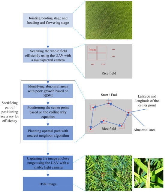
Figure 2.
The main processing flow of the proposed method.
2.1. Far View with Multispectral UAV
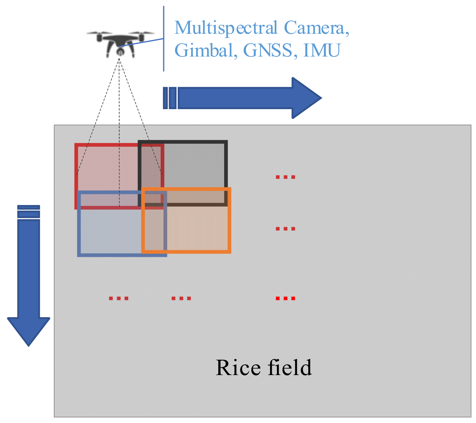
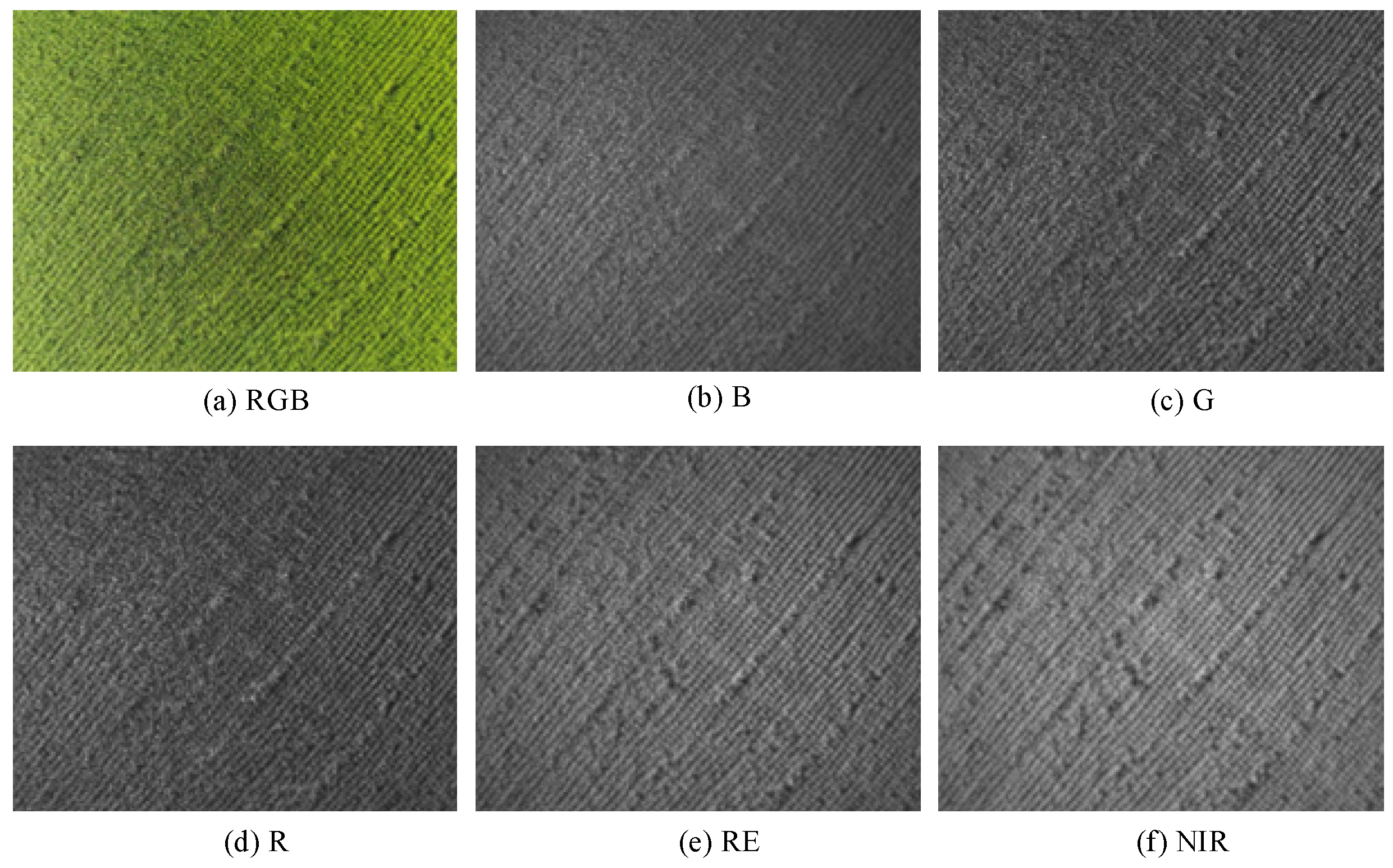
A UAV equipped with a multispectral camera, GNSS, IMU, and gimbal is used to perform an aerial orthophoto scanning at a high altitude on the target field, as shown in Figure 3, and the position and orientation information obtained from GNSS and IMU is recorded in the multispectral images for positioning. A multispectral image taken by DJI Phantom 4 Multispectral (P4M) is shown in Figure 4, including visible light (RGB), blue (B), green (G), red (R), red edge (RE), and NIR.
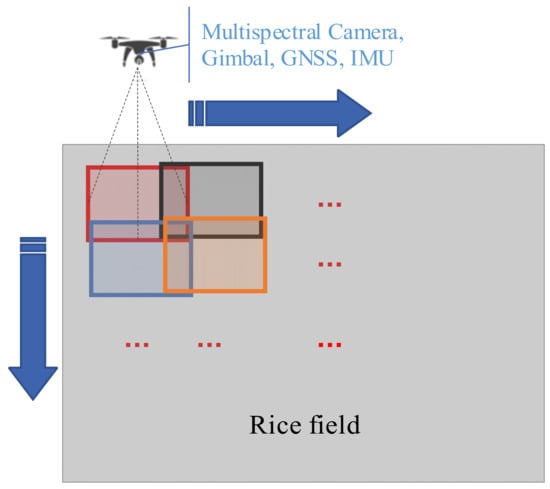
Figure 3.
Orthophoto scanning.
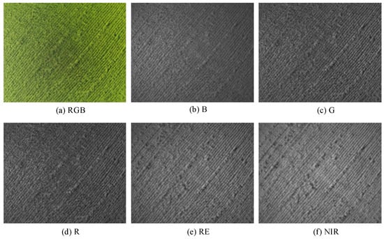
Figure 4.
Multispectral image (GSD: 1.59 cm/pixel, resolution: 1600 × 1300, and size: 25 m × 20 m).
2.2. Identification of Abnormal Areas
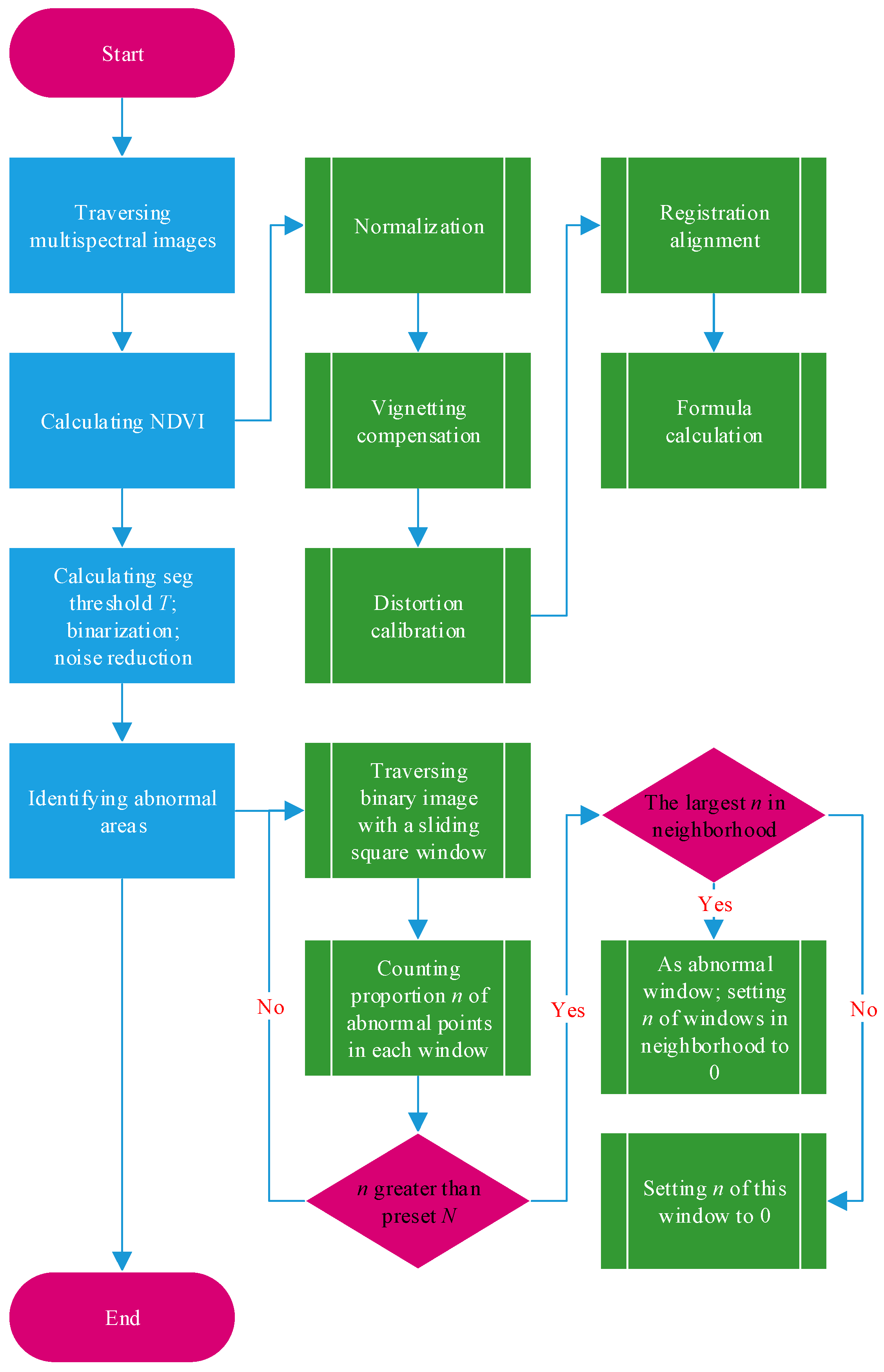
Abnormal conditions such as diseases and pests, lack of fertilizer, lodging, etc., usually lead to poor crop growth [30], and the main purpose of field inspection is to find abnormalities. Therefore, the idea of this paper is to regard the area with poor growth as a suspicious abnormal area and then accurately identify the area at a low altitude to achieve both efficiency and precision. As one of the most widely used VIs currently, the NDVI is used to judge the growth status of rice in this paper [31,32]. In actual production, due to noise interference from soil, leaf variations, shadows, etc., in the natural rice field environment, the abnormality of the rice canopy, especially the early symptoms of diseases and pests, usually appears as scattered points rather than blocks in the low-spatial-resolution NDVI obtained at a high altitude, which makes it difficult to extract effective regional features from the NDVI [26]. To address this problem, from the perspective of probability and statistics, this paper first identifies the abnormal points from the NDVI and then counts the dense areas of abnormal points to identify the abnormal areas. As such, the identification of abnormal areas is transformed into the detection of abnormal point-dense areas in the NDVI. Based on the above idea, this paper proposes a method for identifying abnormal areas based on the NDVI. The detailed process is shown in Figure 5:

Figure 5.
Flow chart of the method for identifying abnormal areas.
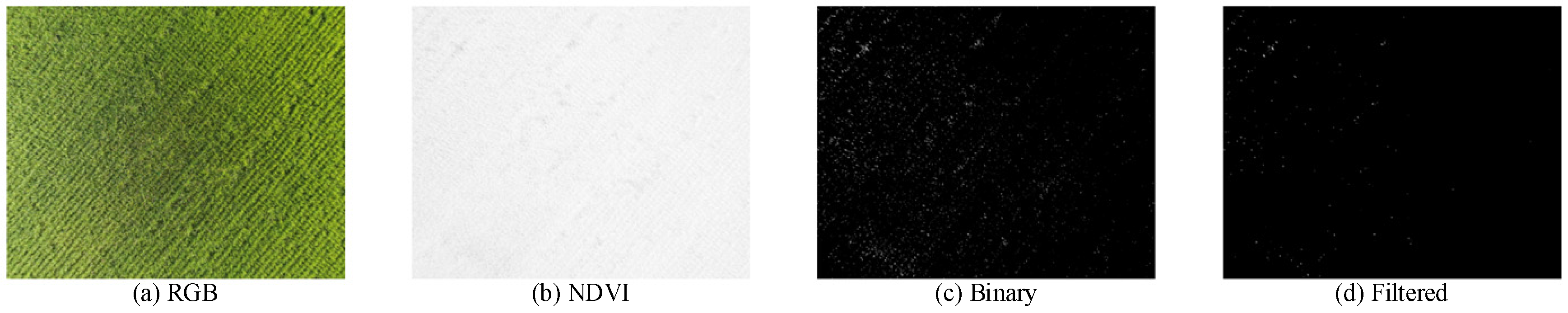
- The multispectral images obtained are traversed to calculate NDVIs with Equation (1) [32]. One of the results is shown in Figure 6b.
 Figure 6. Example of image processing (GSD: 1.59 cm/pixel, resolution: 1600 × 1300, and size: 25 m × 20 m).
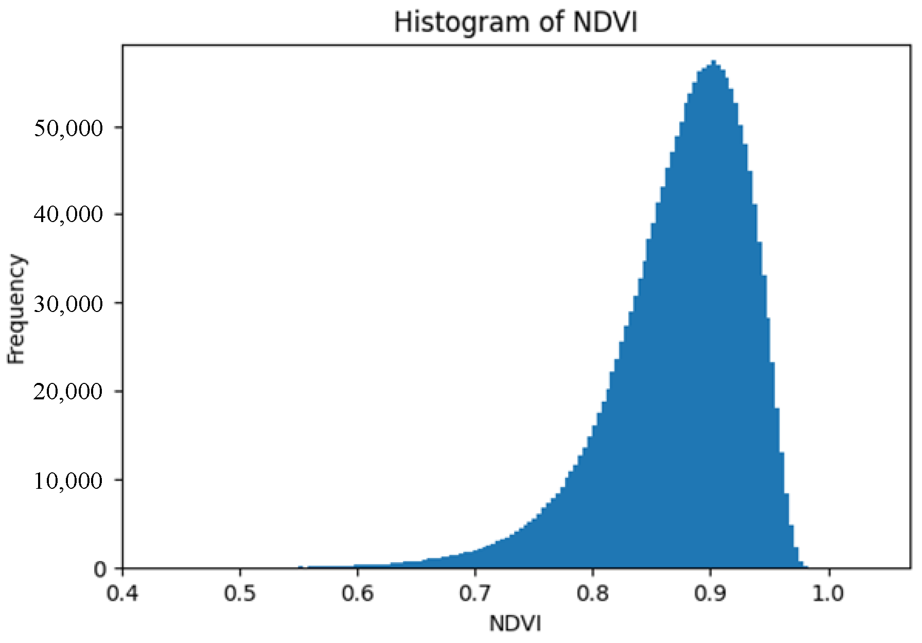
 - In actual production, due to many factors such as different varieties, different growth periods, different management, and different row spacing and plant spacing, it is impossible to obtain a fixed segmentation threshold T, used to judge an NDVI lower than T as poor growth. Through the statistical analysis of the NDVI, it is found that the histogram of the rice canopy NDVI basically conforms to the bell curve shown in Figure 7, which reminds us of the normal distribution. As a strict mathematical distribution is not required in the engineering application of this paper, it can be assumed that the rice canopy NDVI is approximately normally distributed.
 Figure 7. Histogram of rice canopy NDVI (natural field, variety: Xiangya Xiangzhan, growth stage: jointing booting stage).
Normal distribution, also known as Gaussian distribution, is a natural phenomenon, and many events are normally distributed, which is why it is very important in the fields of mathematics, physics, engineering, etc. If the random variable X follows a normal distribution, it can generally be recorded as follows:
Its probability density function is as follows:
where μ is the mathematical expectation value (namely mean value), which determines the location of the distribution; σ is the standard deviation, which determines the magnitude of the distribution.
Assuming that there are n points subject to a normal distribution, the mean value μ and standard deviation σ are, respectively:
In outlier detection based on normal distribution, points outside the value region can be marked as outliers [33].
As the above normal distribution theory, can be adaptively used as the segmentation threshold T for abnormal point detection. In other words, points (namely pixels) with an NDVI less than T are judged as abnormal points with poor growth, thereby obtaining a binary image. One of the binary images is shown in Figure 6c.
- 3.
- Based on the characteristics of random noise, the median filter is used to filter the above binary images to reduce the noise interference caused by soil, shadows, etc. [34]. One of the results is shown in Figure 6d.
- 4.
- Each filtered binary image is traversed with a sliding square window of 1 m2 and 50% overlap, while the proportion n of abnormal points in the window is counted. The 1 m2 square window can be calculated with the GSD (namely, the actual physical distance each pixel represents).
- 5.
- A preset discrimination threshold, N, is used to discriminate between normal and abnormal windows. If n > N, the window is judged as abnormal, while the corresponding area is recorded as an abnormal area with poor growth. Since adjacent abnormal areas are usually caused by the same reason, the neighborhood method is used for deduplication, as shown in Figure 5, to reduce the same adjacent abnormal areas and improve the system efficiency. As a result, only one abnormal area with the largest proportion, n, is retained in the same neighborhood.
2.3. Positioning of the Center Point of the Abnormal Area
In agricultural remote sensing, the current most used positioning method is using photogrammetry technology to reconstruct a two-dimensional (2D) map and then perform positioning (such as DJI Terra) [35]. However, this method requires high along-track and cross-track overlap in the orthophoto scanning mentioned in Section 2.1. The generated large volume of data and the intensive computational requirements for reconstruction require high-performance computers or even computer clusters for processing, which is not only time-consuming but also currently requires human involvement. In addition, the efficiency of data acquisition and map reconstruction in the reconstruction method is insufficient to support high-frequency field inspections of large farms.
In aerial photogrammetry, the collinearity equation is one of the fundamental formulas that describes the mathematical relationship between the object point, image point, and projection center (typically the lens center), stating that they lie on the same line [36]:
where (x, y) are the image point coordinates in the image plane; xo, yo, and f are the internal orientation parameters of the camera; (Xs, Ys, Zs) are the object space coordinates of the camera position; (XA, YA, ZA) are the object space coordinates of the object point; ai, bi, and ci (i = 1, 2, 3) are the nine direction cosines, composed of the three exterior orientation angle parameters ψ, ω, and κ of the image, as shown in Equation (8).
Among these parameters, xo, yo, and f are fixed camera parameters; Xs, Ys, and Zs can be measured by GNSS; and ψ, ω, and κ can be measured by IMU. If ZA (namely, the elevation) is known, the object point (XA, YA) corresponding to the image point (x, y) can be obtained by the collinearity Equations (6) and (7). In other words, single-image positioning can be achieved by combining the digital elevation model (DEM) and the collinearity equation.
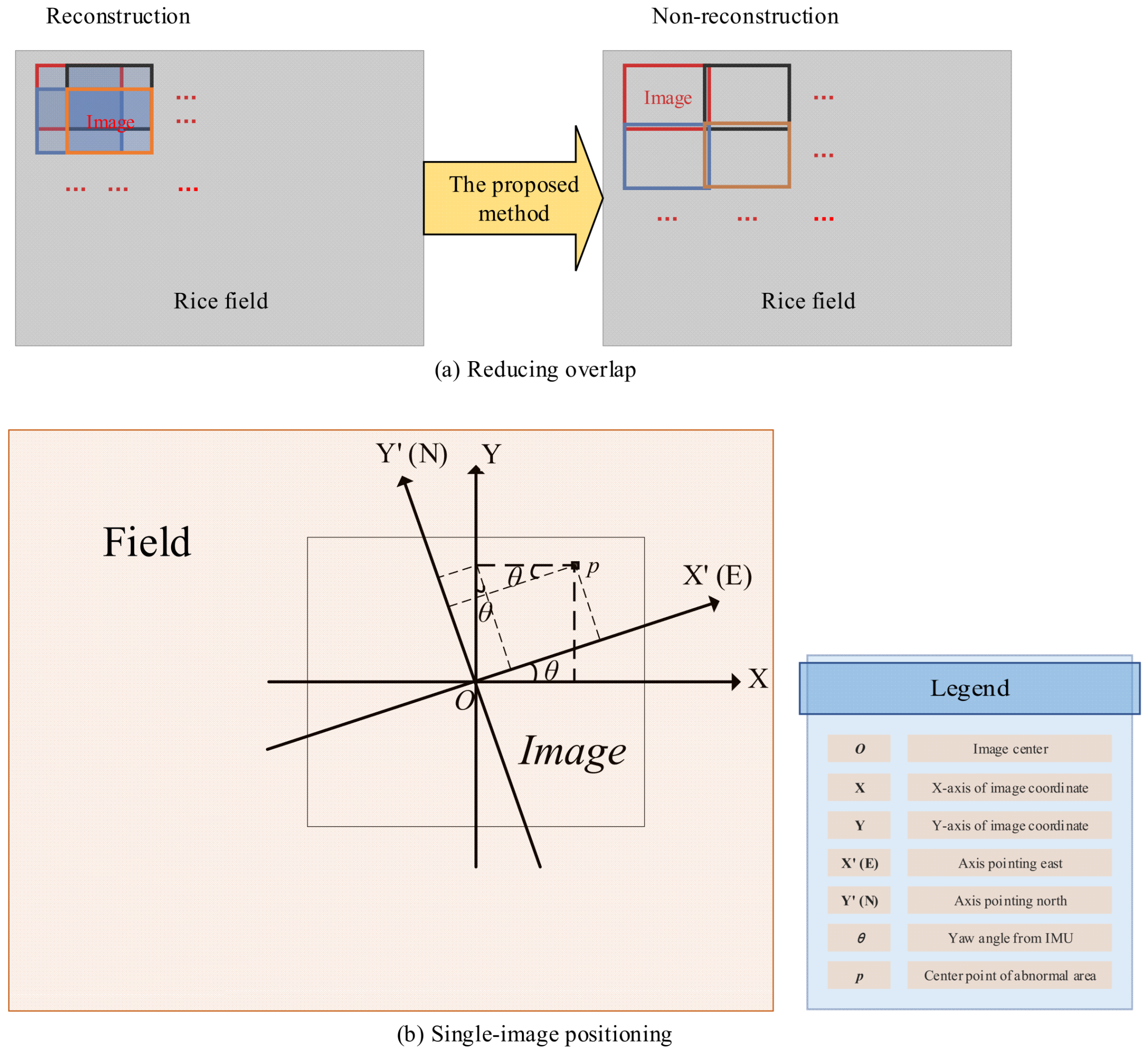
In order to reduce data volume and computational requirements and improve the overall efficiency and automation performance of the system, the positioning approach in this paper is to sacrifice part of positioning accuracy for system efficiency. First, the orthophoto scanning mentioned in Section 2.1 is performed with low overlap; secondly, taking advantage of prior knowledge that the rice canopy is approximately flat [37], the position and orientation information recorded in the orthophoto is used to achieve single-image positioning based on the above theory. In this paper, the center point p of the abnormal area is chosen as the positioning point. The reducing overlap schematic diagram and the single-image positioning schematic diagram are shown in Figure 8a,b, respectively. The detailed process of single-image positioning is shown in Figure 9:
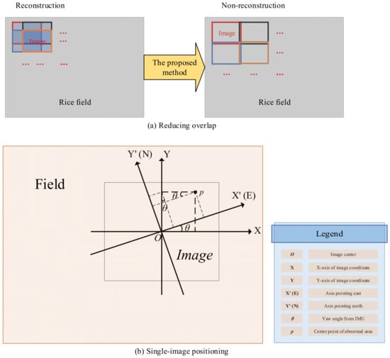
Figure 8.
Reducing overlap and single-image positioning.
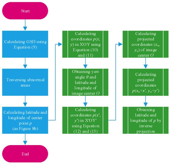
Figure 9.
Flow chart of single-image positioning.
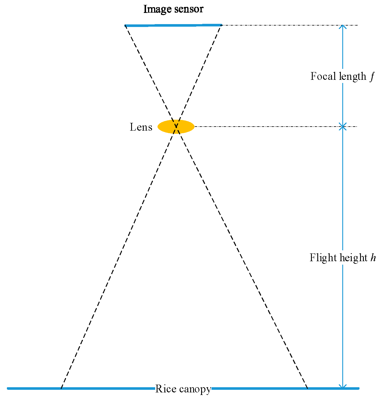
- As shown in Figure 10, the GSD is calculated as follows using the flight height h and camera parameters:
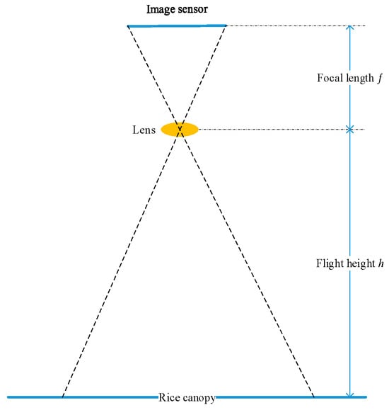 Figure 10. GSD schematic diagram.
 - Based on the GSD, the coordinates (x, y) of the center point p in the Cartesian coordinate system XOY with the image center point O as the origin are calculated:
- The coordinates (x′, y′) of the center point p in the northeast Cartesian coordinate system X′OY′ with the image center point O as the origin are calculated with the yaw angle θ from the orientation information recorded in the image:where Y’(N) and X’(E) in Figure 8b point to the true north (N) and true east (E) directions, respectively. In general, the coordinates in the non-northeast coordinate system are mapped to the northeast coordinate system using only the yaw angle θ.
- From the recorded position information in the image, the latitude and longitude of the image center point O are obtained, and the corresponding projected coordinates (xo, yo) can be obtained by applying the Gauss–Krüger projection [38]. Therefore, the projected coordinates of the center point p can be calculated as (xo + x′, yo + y′). Finally, the latitude and longitude of point p can be obtained by performing the inverse Gauss–Krüger projection.
2.4. Path Planning
Since there are usually multiple identified and positioned abnormal areas in natural fields, it is necessary to plan a path to efficiently traverse these areas. This is a typical traveling salesman problem (TSP), which belongs to the class of NP-complete problems [39]. There is no perfect algorithm that can solve the optimal path in polynomial time. The mathematical description of TSP is as follows:
where G is a complete undirected graph composed of n vertices; V is the set of vertices; and E is the set of edges. The objective is to find an optimal vertex arrangement that minimizes the following:
where is the edge weight from vertex to vertex .
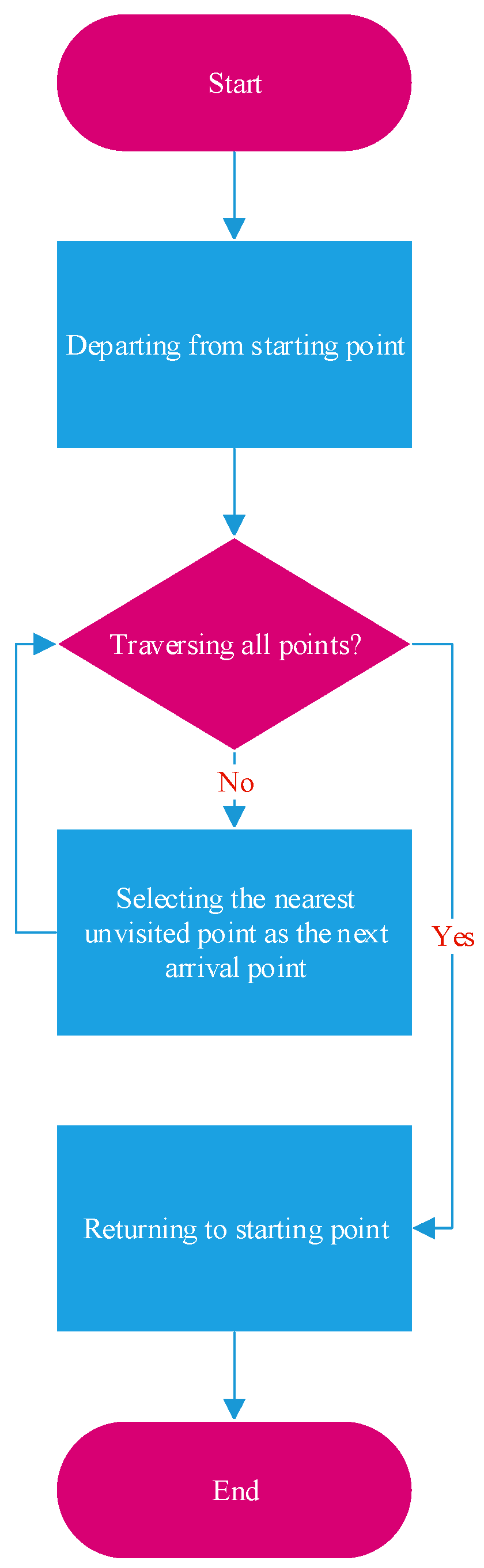
In order to reduce computational complexity, this paper adopts a simple nearest-neighbor algorithm to solve the approximate optimal path [40]. Although the nearest-neighbor algorithm is straightforward, it does not guarantee finding the optimal path. The algorithm flow is illustrated in Figure 11. Starting from the initial vertex v1, at each step, the nearest unvisited vertex is selected as the next destination vertex , until all vertices have been visited once before finally returning to the initial vertex v1. Here, the distance (namely the edge weight ) is defined as the Euclidean distance of the Gauss–Krüger projected coordinates, which is calculated as Equation (18).

Figure 11.
Nearest-neighbor algorithm.
2.5. Close Look with Visible Light UAV
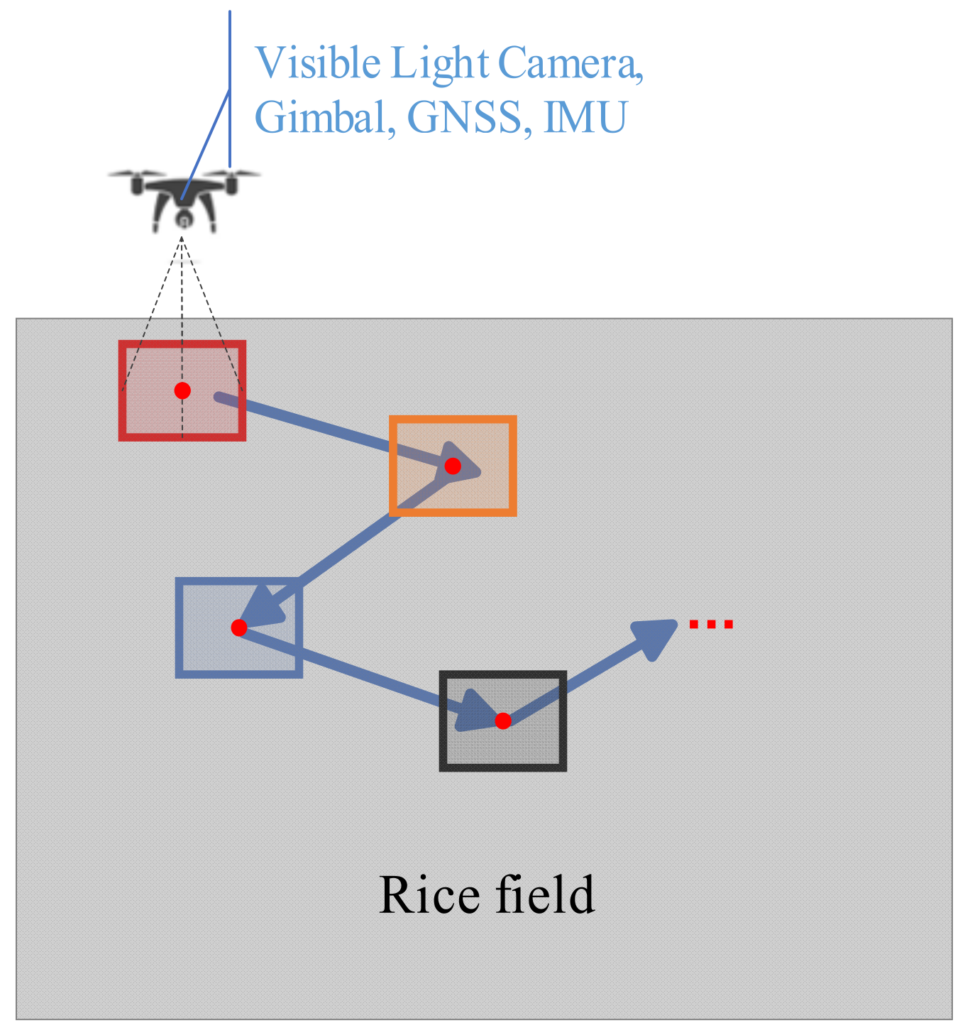
Finally, a UAV equipped with a visible light camera, GNSS, IMU, and gimbal is used to autonomously fly along the planned path and capture HSR images of the abnormal areas at close range, as shown in Figure 12. GNSS is used for navigation and positioning to the center of the abnormal area, while IMU and gimbal control the shooting angle. In order to obtain rich visual features, it is preferable to use a high-definition telephoto camera.
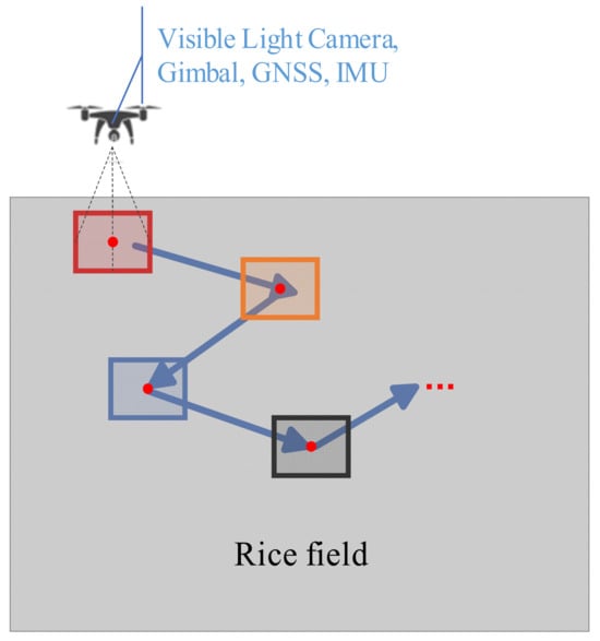
Figure 12.
Low-flying waypoint shooting.
3. Results
3.1. Experiments
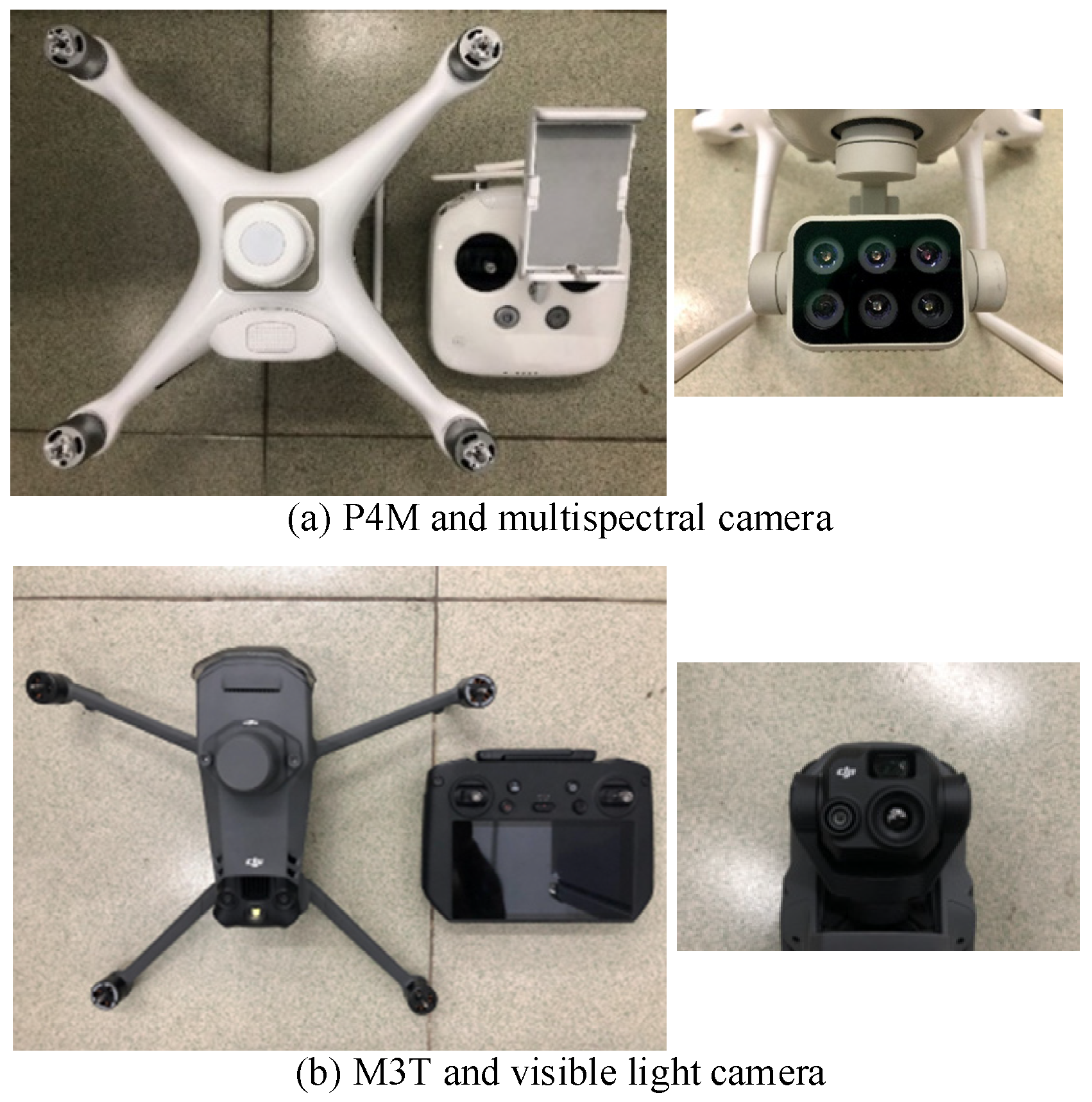
To verify the feasibility and effectiveness of the proposed method, the entire process was implemented using the Python programming language. Experiments were conducted in the Simiao Rice Modern Agricultural Industrial Park (as shown in Figure 13), Zhucun Street, Zengcheng District, Guangzhou City, Guangdong Province, China, using DJI UAVs P4M and Mavic 3 Thermal (M3T) (as shown in Figure 14 and introduced in Table 2). The rice varieties included 19 Xiang and Xiangya Xiangzhan. In addition, the experiments took place from 1 May to 30 June 2023, between 10:00 a.m. and 04:00 p.m., under clear weather conditions with no wind or a light breeze.
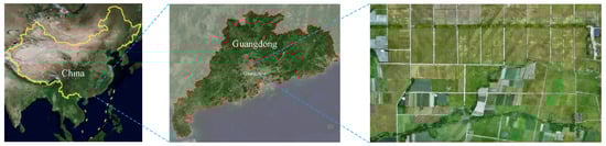
Figure 13.
Geographical location of the experimental area.
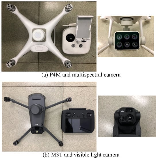
Figure 14.
P4M and M3T.
Table 2.
Function introduction of P4M and M3T.
Experimental procedures and parameter settings were as follows:
- Utilizing the mapping aerial photography function of P4M, the experimental fields were orthographically scanned (camera parameters are introduced in Table 2) at a flight height of 30 m with 10% overlap of both along track and cross track. The gimbal pitch angle was set to −90°, capturing multispectral images at equidistant intervals with a time interval of 2 s.
- Following the steps outlined in the P4 Multispectral Image Processing Guide (https://dl.djicdn.com/downloads/p4-multispectral/20200717/P4_Multispectral_Image_Processing_Guide_EN.pdf, accessed on 1 April 2023), the NDVI was calculated to identify abnormal areas using the proposed method. The size of the median filter was set to 5 × 5, the discrimination threshold N was set to 2%, and the size of the deduplication neighborhood was set to 9 × 9 (i.e., only one abnormal area was retained within a range of 2 m).
- The geographical location of the center point of the identified abnormal area was determined using the single-image positioning method proposed in this paper, followed by path planning using the nearest-neighbor algorithm.
- Finally, the planned path and photography actions were executed using the waypoint flight function of M3T, with a flight height of 5 m, flight speed of 5 m/s, and a telephoto camera selected (camera parameters are introduced in Table 2).
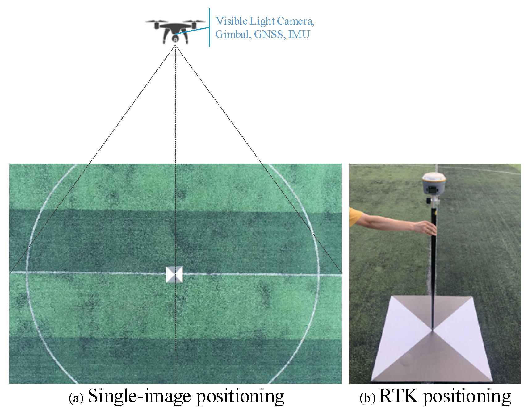
In addition, to verify the accuracy of single-image positioning, an experiment was conducted at the Huashan District Football Field of South China Agricultural University, Tianhe District, Guangzhou City, Guangdong Province, China, as shown in Figure 15. A self-made 1 m × 1 m black-and-white positioning board was used as a marker. The latitude and longitude of the center point of the positioning board were measured as the true coordinates using the Huace Zhonghui i70 intelligent RTK receiver (planar accuracy: ±(2.5 + 0.5 × 10⁻⁶ × D) mm and elevation accuracy: ±(5 + 0.5 × 10⁻⁶ × D) mm). At a flight height of 30 m, the P4M UAV was moved to position the positioning board in different locations within the images (center, sides, corners, etc.). A total of 30 images were captured, and the proposed single-image positioning method was used to calculate the latitude and longitude of the center point of the positioning board. The results were compared with the true coordinates to calculate the AAE. Furthermore, 10 positioning boards were placed on the football field, and the center point coordinates were measured as the true coordinates, also using the Huace Zhonghui i70 intelligent RTK receiver. The P4M UAV performed mapping aerial photography three times at a flight height of 30 m (80% along-track overlap, 70% cross-track overlap, and −90° of gimbal pitch angle, capturing images at equidistant intervals with a time interval of 2 s). The DJI Terra software (Version 3.6.0) was used to reconstruct three 2D maps, then 30 center point coordinates of the black-and-white positioning boards were determined on the 2D maps and compared with the true coordinates to calculate the AAE.
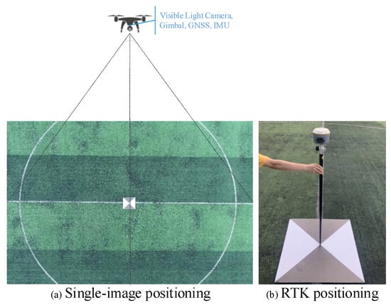
Figure 15.
Single-image positioning and RTK positioning.
3.2. Experimental Results
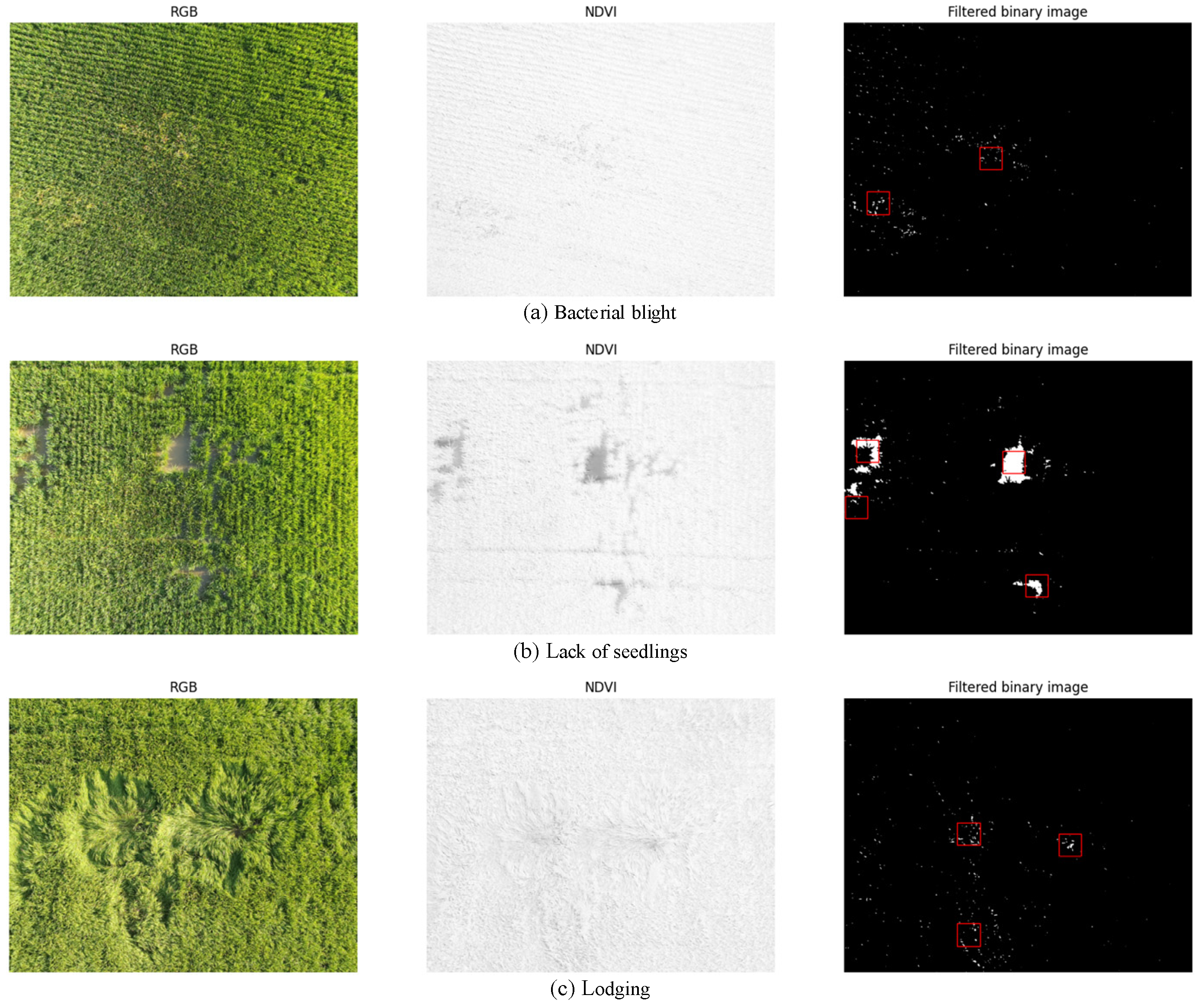
Some identification results of abnormal areas are shown in Figure 16.
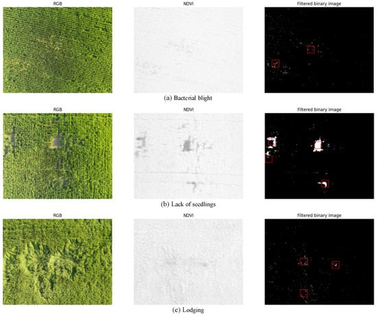
Figure 16.
Identification results of abnormal areas (marked by red box).
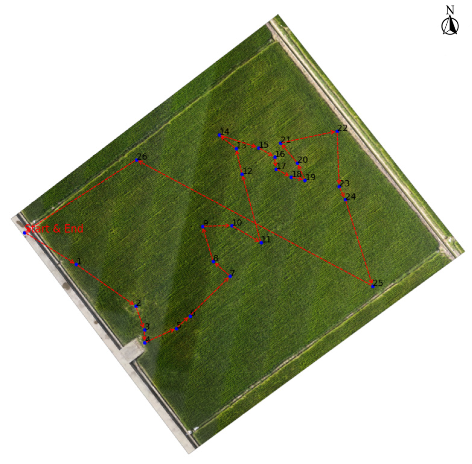
The planned path obtained during the experiment conducted in the field shown in Figure 17 is depicted by the red dashed line in the figure. In addition, the blue dots represent the center points of the identified abnormal areas, “Start & End” indicates the takeoff and landing points of the UAV, and the arrows indicate the direction of the path.
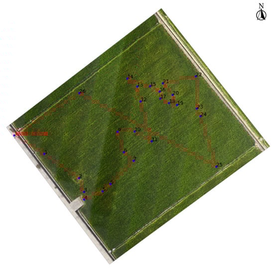
Figure 17.
Example of path planning.
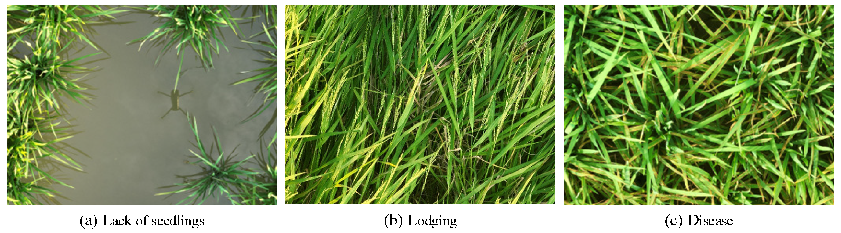
Some HSR images of abnormal areas captured by M3T are shown in Figure 18.
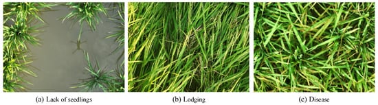
Figure 18.
HSR images of abnormal areas.
4. Discussion
The experimental results indicate that the proposed method successfully identifies abnormal areas, including symptomatic diseases and pests, lack of seedlings, lodging, etc. As shown in Figure 16, bacterial blight, lack of seedlings, and lodging are depicted, and only one abnormal area with the largest proportion n is retained within a 2 m range, demonstrating the feasibility and effectiveness of the method. Additionally, by adjusting the discrimination threshold N, the sensitivity of abnormal detection can be controlled. A smaller N value increases sensitivity but may result in misidentification of non-abnormal areas, reducing system efficiency. Conversely, a larger N value decreases sensitivity and may lead to missed detection of early abnormalities. The size of the deduplication neighborhood can be adjusted to retain only one abnormal area with the largest proportion n within a certain range, thereby controlling the number and density of abnormal areas that require low-altitude traversal.
In the approximately flat football field, the AAE of the single-image positioning method proposed in this paper is 13.2 cm, while the AAE of the reconstruction positioning is 4.3 cm. In the application of this paper, the real size of abnormal areas is usually much larger than 13.2 cm, indicating that the positioning accuracy meets the requirements of the application. Generally, the efficiency and accuracy comparison between single-image positioning and reconstruction positioning are shown in Table 3. Although there is a slight loss in positioning accuracy within an acceptable range, the flight efficiency is greatly improved, the number of images is significantly reduced, and the time-consuming process of reconstruction is eliminated, which proves the feasibility and effectiveness of single-image positioning.
Table 3.
Efficiency and accuracy comparison between single-image positioning and reconstruction positioning.
According to Equation (9) and Table 2, GSDs of the Figure 16 and Figure 18 are 1.59 cm/pixel and 0.027 cm/pixel, respectively, which indicates that the spatial resolution is greatly improved when flying at a lower altitude compared to a higher altitude. At the leaf and canopy scale, many studies have shown that it is possible to accurately capture diseases and pests damage characteristics on rice leaves by acquiring HSR images [26]. In addition, the input image size for most used deep-learning classification models is 224 pixels × 224 pixels [15,16,17,18,19,20,21,22], and the width of mature rice leaves typically ranges from 2 cm to 3 cm [41]. If extracting an image patch of 224 pixels × 224 pixels from the HSR images obtained by the proposed method, the rice leaf will occupy approximately 74 to 111 pixels, accounting for about 1/3 to 1/2 of the image patch. Therefore, we can extract image patches from the HSR images without downsampling to perform even leaf-scale deep-learning classification and identify specific types of diseases and pests.
5. Conclusions
In summary, the proposed method in this paper enables autonomous field inspection by UAVs to acquire HSR images of abnormal areas in the rice canopy. The HSR images can provide high-quality data for subsequent automatic identification of field abnormalities such as diseases and pests, thereby offering technical support for the realization of the UAV-based automatic rice field inspection system. The experimental results demonstrate that the proposed method can identify abnormal areas, including diseases and pests, lack of seedlings, lodging, etc. The AAE of single-image positioning is 13.2 cm, which meets the accuracy requirements of the application in this paper. Additionally, the efficiency is greatly improved compared to reconstruction positioning. The GSD of the acquired HSR image can reach 0.027 cm/pixel, or even smaller, which meets the resolution requirements of even leaf-scale deep-learning classification.
The proposed method in this paper can also provide references for the automatic field management of other crops, such as wheat. Additionally, the method for identifying and positioning abnormal areas in this paper can provide targeted objectives for other field operations, such as ground-based crop phenotyping, thereby reducing workload and labor intensity.
In future research work, we will study the automatic identification of diseases and pests based on HSR images captured by UAVs, which will provide further technical support for the realization of the UAV-based automatic rice field inspection system. Additionally, we will explore the feasibility and effectiveness of applying the proposed method to other crops, such as wheat and peanuts.
Author Contributions
Conceptualization, Q.Z., X.L., L.H. and J.H.; methodology, Q.Z., X.L., L.H. and J.H.; software, Q.Z. and C.L.; validation, Q.Z. and C.L.; formal analysis, Q.Z.; investigation, Q.Z.; resources, Q.Z., X.L., L.H., J.H., P.W. and R.Z.; data curation, Q.Z., X.L., L.H., C.L. and J.H.; writing—original draft preparation, Q.Z.; writing—review and editing, Q.Z., X.L., L.H., J.H., P.W. and R.Z.; visualization, Q.Z., L.H., C.L., J.H., P.W. and R.Z.; supervision, X.L., L.H., J.H., P.W. and R.Z.; project administration, X.L. and L.H.; funding acquisition, X.L. and L.H. All authors have read and agreed to the published version of the manuscript.
Funding
This research was funded by the Laboratory of Lingnan Modern Agriculture Project (NT2021009) and the Science and Technology Planning Project of Guangdong Province (2021B1212040009).
Data Availability Statement
The data that support this study will be shared upon reasonable request to the corresponding author.
Acknowledgments
We would like to thank our partners at the Zengcheng Simiao Rice Modern Agricultural Industrial Park and the Zengcheng Teaching Base of South China Agricultural University for their help and support in field management and machine maintenance.
Conflicts of Interest
The authors declare no conflict of interest.
References
- Brolley, M. Rice security is food security for much of the world. Rice Today Int. Rice Res. Inst. (IRRI) DAPO Box 2015, 7777, 30–32. [Google Scholar]
- Durand-Morat, A.; Nalley, L.L.; Thoma, G. The implications of red rice on food security. Glob. Food Secur. 2018, 18, 62–75. [Google Scholar] [CrossRef]
- Khan, M.I.R.; Palakolanu, S.R.; Chopra, P.; Rajurkar, A.B.; Gupta, R.; Iqbal, N.; Maheshwari, C. Improving drought tolerance in rice: Ensuring food security through multi-dimensional approaches. Physiol. Plant. 2021, 172, 645–668. [Google Scholar] [CrossRef] [PubMed]
- Deng, N.; Grassini, P.; Yang, H.; Huang, J.; Cassman, K.G.; Peng, S. Closing yield gaps for rice self-sufficiency in China. Nat. Commun. 2019, 10, 1725. [Google Scholar] [CrossRef] [PubMed]
- Zhang, H.; Hou, D.P.; Peng, X.L.; Shao, S.M.; Jing, W.J.; Gu, J.F.; Liu, L.J.; Wang, Z.Q.; Liu, Y.Y.; Yang, J.C. Optimizing integrative cultivation management improves grain quality while increasing yield and nitrogen use efficiency in rice. J. Integr. Agric. 2019, 18, 2716–2731. [Google Scholar] [CrossRef]
- Hamza, A.; Riaz, F.; Abid, S.; Raza, U.; Holderbaum, W.; Chowdhry, B.S. A Comprehensive Study of the Role of Self-Driving Vehicles in Agriculture: A Review. In Proceedings of the 2023 7th International Multi-Topic ICT Conference (IMTIC), Jamshoro, Pakistan, 10–12 May 2023; pp. 1–7. [Google Scholar]
- Barrile, V.; Simonetti, S.; Citroni, R.; Fotia, A.; Bilotta, G. Experimenting agriculture 4.0 with sensors: A data fusion approach between remote sensing, UAVs and self-driving tractors. Sensors 2022, 22, 7910. [Google Scholar] [CrossRef] [PubMed]
- Mogili, U.M.R.; Deepak, B. Review on application of drone systems in precision agriculture. Procedia Comput. Sci. 2018, 133, 502–509. [Google Scholar] [CrossRef]
- Maes, W.H.; Steppe, K. Perspectives for remote sensing with unmanned aerial vehicles in precision agriculture. Trends Plant Sci. 2019, 24, 152–164. [Google Scholar] [CrossRef]
- Jiang, J.; Wu, Y.; Liu, Q.; Liu, Y.; Cao, Q.; Tian, Y.; Zhu, Y.; Cao, W.; Liu, X. Developing an efficiency and energy-saving nitrogen management strategy for winter wheat based on the UAV multispectral imagery and machine learning algorithm. Precis. Agric. 2023, 24, 2019–2043. [Google Scholar] [CrossRef]
- Yu, F.; Jin, Z.; Guo, S.; Guo, Z.; Zhang, H.; Xu, T.; Chen, C. Research on weed identification method in rice fields based on UAV remote sensing. Front. Plant Sci. 2022, 13, 1037760. [Google Scholar] [CrossRef]
- Wang, Y.P.; Chang, Y.C.; Shen, Y. Estimation of nitrogen status of paddy rice at vegetative phase using unmanned aerial vehicle based multispectral imagery. Precis. Agric. 2022, 23, 1–17. [Google Scholar] [CrossRef]
- Stavrakoudis, D.; Katsantonis, D.; Kadoglidou, K.; Kalaitzidis, A.; Gitas, I.Z. Estimating rice agronomic traits using drone-collected multispectral imagery. Remote Sens. 2019, 11, 545. [Google Scholar] [CrossRef]
- Jha, K.; Doshi, A.; Patel, P.; Shah, M. A comprehensive review on automation in agriculture using artificial intelligence. Artif. Intell. Agric. 2019, 2, 1–12. [Google Scholar] [CrossRef]
- Rahman, C.R.; Arko, P.S.; Ali, M.E.; Khan, M.A.I.; Apon, S.H.; Nowrin, F.; Wasif, A. Identification and recognition of rice diseases and pests using convolutional neural networks. Biosyst. Eng. 2020, 194, 112–120. [Google Scholar] [CrossRef]
- Chen, J.; Zhang, D.; Nanehkaran, Y.A.; Li, D. Detection of rice plant diseases based on deep transfer learning. J. Sci. Food Agric. 2020, 100, 3246–3256. [Google Scholar] [CrossRef] [PubMed]
- Shrivastava, V.K.; Pradhan, M.K.; Thakur, M.P. Application of pre-trained deep convolutional neural networks for rice plant disease classification. In Proceedings of the 2021 International Conference on Artificial Intelligence and Smart Systems (ICAIS), Coimbatore, India, 25–27 March 2021; pp. 1023–1030. [Google Scholar]
- Patil, R.R.; Kumar, S. Rice-fusion: A multimodality data fusion framework for rice disease diagnosis. IEEE Access 2022, 10, 5207–5222. [Google Scholar] [CrossRef]
- Anami, B.S.; Malvade, N.N.; Palaiah, S. Deep learning approach for recognition and classification of yield affecting paddy crop stresses using field images. Artif. Intell. Agric. 2020, 4, 12–20. [Google Scholar] [CrossRef]
- Wang, C.; Ye, Y.; Tian, Y.; Yu, Z. Classification of nutrient deficiency in rice based on CNN model with Reinforcement Learning augmentation. In Proceedings of the 2021 International Symposium on Artificial Intelligence and its Application on Media (ISAIAM), Xi’an, China, 21–23 May 2021; pp. 107–111. [Google Scholar]
- Dey, B.; Haque, M.M.U.; Khatun, R.; Ahmed, R. Comparative performance of four CNN-based deep learning variants in detecting Hispa pest, two fungal diseases, and NPK deficiency symptoms of rice (Oryza sativa). Comput. Electron. Agric. 2022, 202, 107340. [Google Scholar] [CrossRef]
- Hu, P. A Rice Pest Identification Method Based on a Convolutional Neural Network and Migration Learning. J. Circuits Syst. Comput. 2023, 32, 2350089. [Google Scholar] [CrossRef]
- Su, J.; Liu, C.; Coombes, M.; Hu, X.; Wang, C.; Xu, X.; Li, Q.; Guo, L.; Chen, W.H. Wheat yellow rust monitoring by learning from multispectral UAV aerial imagery. Comput. Electron. Agric. 2018, 155, 157–166. [Google Scholar] [CrossRef]
- Devia, C.A.; Rojas, J.P.; Petro, E.; Martinez, C.; Mondragon, I.F.; Patiño, D.; Rebolledo, M.C.; Colorado, J. High-throughput biomass estimation in rice crops using UAV multispectral imagery. J. Intell. Robot. Syst. 2019, 96, 573–589. [Google Scholar] [CrossRef]
- Kim, H.; Kim, W.; Kim, S.D. Damage assessment of Rice crop after toluene exposure based on the vegetation index (VI) and UAV multispectral imagery. Remote Sens. 2020, 13, 25. [Google Scholar] [CrossRef]
- Zheng, Q.; Huang, W.; Xia, Q.; Dong, Y.; Ye, H.; Jiang, H.; Chen, S.; Huang, S. Remote Sensing Monitoring of Rice Diseases and Pests from Different Data Sources: A Review. Agronomy 2023, 13, 1851. [Google Scholar]
- Bewke, G.B. Review on integrated pest management of important disease and insect pest of rice (Oryzae sativa L.). World Sci. News 2018, 100, 184–196. [Google Scholar]
- Zhang, K.; Ge, X.; Shen, P.; Li, W.; Liu, X.; Cao, Q.; Zhu, Y.; Cao, W.; Tian, Y. Predicting rice grain yield based on dynamic changes in vegetation indexes during early to mid-growth stages. Remote Sens. 2019, 11, 387. [Google Scholar] [CrossRef]
- Goswami, S.; Gamon, J.; Vargas, S.; Tweedie, C. Relationships of NDVI, Biomass, and Leaf Area Index (LAI) for six key plant species in Barrow, Alaska. PeerJ PrePrints 2015, 3, e913v1. [Google Scholar] [CrossRef]
- Nie, L.; Peng, S. Rice production in China. In Rice Production Worldwide; Springer: Cham, Switzerland, 2017; pp. 32–52. [Google Scholar] [CrossRef]
- Zhang, Z.; Zhu, L. A Review on Unmanned Aerial Vehicle Remote Sensing: Platforms, Sensors, Data Processing Methods, and Applications. Drones 2023, 7, 398. [Google Scholar]
- Rouse, J.W., Jr.; Haas, R.H.; Deering, D.W.; Schell, J.A.; Harlan, J.C. Monitoring the Vernal Advancement and Retrogradation (Green Wave Effect) of Natural Vegetation; No. E75-10354; NASA CR: Clear Lake, TX, USA, 1974.
- Han, J.; Kamber, M.; Pei, J. Outlier detection. Data mining: Concepts and techniques. In Proceedings of the 2013 International Conference on Machine Intelligence and Research Advancement, Katra, India, 21–23 December 2013; pp. 543–584. [Google Scholar]
- Hwang, H.; Haddad, R.A. Adaptive median filters: New algorithms and results. IEEE Trans. Image Process. 1995, 4, 499–502. [Google Scholar] [CrossRef]
- Rueda-Ayala, V.P.; Peña, J.M.; Höglind, M.; Bengochea-Guevara, J.M.; Andújar, D. Comparing UAV-based technologies and RGB-D reconstruction methods for plant height and biomass monitoring on grass ley. Sensors 2019, 19, 535. [Google Scholar] [CrossRef]
- Wolf, P.R.; Dewitt, B.A.; Wilkinson, B.E. Elements of Photogrammetry: With Applications in GIS; McGraw-Hill: New York, NY, USA, 2000. [Google Scholar]
- Katul, G.G.; Leuning, R.; Kim, J.; Denmead, O.T.; Miyata, A.; Harazono, Y. Estimating CO2 source/sink distributions within a rice canopy using higher-order closure model. Bound.-Layer Meteorol. 2001, 98, 103–125. [Google Scholar] [CrossRef]
- Deakin, R.E.; Hunter, M.N.; Karney, C.F.F. The gauss-krüger projection. In Proceedings of the 23rd Victorian Regional Survey Conference, Warrnambool, VIC, Australia, 10–12 September 2010; pp. 1–20. [Google Scholar]
- Hoffman, K.L.; Padberg, M.; Rinaldi, G. Traveling salesman problem. Encycl. Oper. Res. Manag. Sci. 2013, 1, 1573–1578. [Google Scholar]
- Abdulkarim, H.A.; Alshammari, I.F. Comparison of algorithms for solving traveling salesman problem. Int. J. Eng. Adv. Technol. 2015, 4, 76–79. [Google Scholar]
- Wangpan, T.; Taka, T.; Tangjang, S. On-farm Diversity of Indigenous Rice (Oryza Sativa L.) Landraces in Border of Eastern Himalaya. Pertanika J. Trop. Agric. Sci. 2018, 41, 393–410. [Google Scholar]


Disclaimer/Publisher’s Note: The statements, opinions and data contained in all publications are solely those of the individual author(s) and contributor(s) and not of MDPI and/or the editor(s). MDPI and/or the editor(s) disclaim responsibility for any injury to people or property resulting from any ideas, methods, instructions or products referred to in the content. |
© 2023 by the authors. Licensee MDPI, Basel, Switzerland. This article is an open access article distributed under the terms and conditions of the Creative Commons Attribution (CC BY) license (https://creativecommons.org/licenses/by/4.0/).