Article

Design and Testing of a Wheeled Crop-Growth-Monitoring Robot Chassis

1
College of Agriculture, Nanjing Agricultural University, Nanjing 210095, China
2
School of Information Engineering, Huzhou University, Huzhou 313000, China
3
National Information Agricultural Engineering Technology Center, Nanjing Agricultural University, Nanjing 210095, China
4
Jiangsu Collaborative Innovation Center for the Technology and Application of Internet of Things, Nanjing Agricultural University, Nanjing 210095, China
*
Author to whom correspondence should be addressed.
Agronomy 2023, 13(12), 3043; https://doi.org/10.3390/agronomy13123043
Submission received: 3 October 2023 / Revised: 4 November 2023 / Accepted: 10 December 2023 / Published: 12 December 2023
(This article belongs to the Section Precision and Digital Agriculture)

Abstract

:
The high-flux acquisition of crop growth information can be realized using field monitoring robotic platforms. However, most of the existing agricultural monitoring robots have been converted from expensive commercial platforms, and they thus have a hard time adapting to the farmland working environment, let alone satisfying the basic requirements of sensor testing. To address these problems, a wheeled crop-growth-monitoring robot that features the accurate, nondestructive, and efficient acquisition of crop growth information was developed based on the cultivation characteristics of wheat, the obstacle characteristics of the wheat field, and the monitoring mechanism of spectral sensors. By analyzing the phenotypic structural change characteristics and the requirements for the row spacing of different wheat varieties throughout the growth period, a four-wheel mobile chassis was designed with an adjustable wheel track and a high-clearance body structure that can effectively eliminate the risk of the robot destroying the wheat during operation. Moreover, considering the requirements for wheeled robots to overcome obstacles in field operations, a three-dimensional (3D) model of the robot was created in Pro/E. Models of obstacles in the field (e.g., pits and bumps) were created in Adams to simulate the operational stability of the robot. The simulation results showed that the mass center displacement of the robot was smaller than 0.2 cm on flat pavement and the maximum mass center displacement was 1.78 cm during obstacle crossing (10 cm deep pits and 10 cm high bumps). The field test showed that the robot equipped with active-light-source crop growth sensors achieved stable, real-time, nondestructive, and accurate acquisition of the canopy vegetation parameters—NDVI (normalized difference vegetation index) and RVI (ratio vegetation index)—and the wheat growth parameters—LAI (leaf area index), LDW (leaf dry weight), LNA (leaf nitrogen accumulation), and LNC (leaf nitrogen content).

1. Introduction

Accurate field water and fertilizer management is an important prerequisite to ensure high crop yield and quality, the sustainable use of farmland, and healthy environmental development [1,2]. However, real-time, nondestructive, and high-flux acquisition of crop growth information is the primary condition for the implementation of accurate field water and fertilizer management [3,4]. Traditionally, crop growth information is acquired by the destructive sampling of plants and through physical and chemical laboratory analysis, which is time-consuming and laborious. To overcome the disadvantages of these traditional methods, a variety of portable crop-growth-monitoring devices based on spectral feature recognition technology have been developed over the past few years, such as Greenseeker, ASD Fieldspec, and RapidScan [5,6,7,8,9]. Although portable devices offer excellent measurement accuracy, they also have shortcomings, such as a dependence on hand-held operation, single-point testing, limited operation areas, and low test efficiency.
To solve the abovementioned problems, unmanned-aerial-vehicle-(UAV)-borne crop-growth-monitoring equipment and vehicle-borne crop-growth-monitoring equipment have emerged. UAVs have been widely used in agriculture owing to their advantages, such as a small and flexible structure, high operability, and immunity to terrain interference [10]. For example, Jin et al. acquired plant density parameters of wheat in the tillering stage using a six-rotor UAV equipped with an RGB camera at a low altitude of 3–7 m [11]. Schirrmann acquired the canopy images of wheat in the booting, flowering, and filling stages using a UAV carrying a consumer-grade RGB camera. These images were used to evaluate the changes in the wheat canopy scale and individual plants [12]. UAVs that carry different types of sensors can obtain crop canopy images efficiently and nondestructively based on the vegetation index, canopy classification, or structural measurement employed [13]. However, their load limit and short endurance make it difficult for UAVs to carry large and heavy high-accuracy sensors, let alone to perform multi-sensor synchronous testing.
Compared with UAV platforms, agricultural machinery platforms offer a higher load capacity and endurance and better satisfy the needs of multi-sensor, real-time, and synchronous testing [14]. In a study by Polo et al., a tractor-mounted LiDAR was used to conduct 3D cloud point scanning in apple, pear, and grape orchards, the result of which showed that the tractor–LiDAR combination could obtain the 3D structural information of fruit trees quickly and with high flux, thus enabling the calculation of crop leaf area, tree-row volume, and the other crop parameters [15]. Crop Circle, GreenSeeker, and Topcon were mounted on a tractor in a cornfield test carried out by Sudduth et al. [16]. It can be inferred that agricultural machinery platforms enjoy irreplaceable advantages concerning their load limit and endurance [17,18,19,20]. Unfortunately, it is difficult to perform wheel track adjustment freely in agricultural machinery platforms, as is needed for accurate row spacing, because of their wide wheels, low chassis, and heavy bodies.
Given the problems that agricultural machinery platforms are exposed to, some research institutions have developed a series of small mobile robotic platforms. Based on chassis type and operation mode, the existing mobile robots can be roughly divided into groups: the track type, the crawler type, the legged type, and the wheeled type. Track robots have been widely studied and have produced fruitful results. For example, PhenoField was designed jointly by Robopec and Meca3d [21], Field Scanalyzer was developed by LemnaTec GmbH, [22] and FieldScan was made by Phenospex [23]. Track robots can carry multiple sensors to monitor a specific area with high repeatability, but the fixed tracks have limited their flexibility and monitoring area. With a crawler structure like the chassis, crawler robots offer excellent stability and adapt well to soft land surfaces, such as sandy land and muddy land [24]. However, these robots are not suitable for inter-row nondestructive operations because of their low-clearance chassis, wide crawlers, and large areas of contact with the ground [25]. Ibex Automation Ltd. developed a small crawler robot for weed identification and precise weeding, but it is difficult to effectively solve the problem of crop crushing because of the low chassis [26]. Legged robots feature a smaller area of contact with the ground and a more flexible and convenient operation, but their application has been limited so far because of the complex control system and costly design [27]. Moreover, as the field surface is not flat enough, the robot cannot run stably, which may lead to rollover.
Wheeled robots not only perform better regarding stable operation, gradability, and obstacle crossing than crawler and legged robots, but their simpler chassis system and lower design cost also better satisfy the needs of agricultural production [28,29,30,31,32]. Based on the chassis of a Husky A200 wheeled robot, an unmanned intelligent vehicle platform was designed by Shafiekhani et al. Since it carries temperature, humidity, light intensity, and image sensors, as well as LIDAR, it can be used to monitor environment information (e.g., temperature, humidity, and light intensity) and the phenotypic information of individual plants (e.g., plant height and chlorophyll content) [33]. Weiss et al. built a 3D model for the chassis of a Volksbot RT3 wheeled robot carrying an FX6 3D Lidar. Automatic navigation control of the mobile platform and automatic classification of crops and soil background were implemented using target detection and positioning [34]. Further, a Husky A200 wheeled robot for farmland purposes was used by Giulio Reina et al. to build a color- and geometric-feature-based terrain evaluation and classification system. The high-torque, four-wheel, independent-drive pattern and the 13-inch-wide tires of the Husky A200 ensured excellent off-road performance and zero-degree differential steering of the platform [35]. Wheeled robots already have relatively mature steering control methods, such as Ackerman steering control, which gives wheeled chassis a greater advantage in the development process of motion control and autonomous navigation technology [36]. Most wheeled robotic platforms used in current research are low-clearance versions or are modified from commercial platforms with fixed chassis. They are stable in operation but are less practical in crop growth monitoring [37]. It is also difficult for them to meet the requirements of different crop-growth-monitoring sensors regarding test height and position. Considering that commercial robotic platforms are primarily designed for spacious and flat road surfaces, soft farmland with considerable friction, pits, bumps, and other obstacles makes stable operation impossible.
To address the abovementioned problems, a wheeled robot chassis for crop growth monitoring was developed in this study. By analyzing the phenotyping structural change characteristics and row spacing requirements of different wheat varieties throughout the growth period, a four-wheel mobile chassis with an adjustable wheel track and a high-clearance body structure was designed to effectively prevent the destruction of wheat during the robot’s operation. Moreover, a 3D wheeled robot model was built in Pro/E. Based on the characteristics of the obstacles in the wheat field, the models of typical wheat field obstacles, such as pits and bumps, were established using Adams. The stability of the wheeled robot when crossing obstacles was also simulated. In addition, the active-light-source crop growth sensor equipped on the wheeled robot enabled it to achieve real-time, nondestructive, and high-flux acquisition of wheat growth information over the whole growth period. Importantly, sensor data collection, analysis, and management, as well as robot operation control, were subject to the centralized control of a self-designed LabVIEW program, which simplified the test flow.

2. Materials and Methods

2.1. Overall Design of the Wheeled Robot

The wheeled crop-growth-monitoring robot chassis consisted of three parts: the mechanical mechanism, the sensing unit, and the control system. The mechanical mechanism consisted of a four-wheel chassis and the main body; the sensing unit contained the environment information sensing module, the operation status sensing module, and the crop growth information sensing module; and the control system, designed in LabVIEW, was used for functions including robot motion control, navigation control, sensor data acquisition, and analysis and management. The robot chassis structure is shown in Figure 1.

2.2. Mechanical Mechanism Design and Dynamic Simulation of Wheeled Robot Chassis

2.2.1. Mechanical Mechanism Design of Wheeled Robot Chassis

Wheat is usually sown with a small row spacing using a drill. The plant’s height can change dramatically during its growth. To avoid the wheeled robot chassis destroying wheat plants during monitoring, it was critical to consider the row spacing requirements and the characteristics of the phenotypic structure of wheat throughout the growth period when creating the mechanical design of the wheeled robot chassis. The plant height changes in ‘Yangmai’ (erect plant type) and ‘Ningmai’ (curve-slant plant type) are shown in Figure 2. The plant heights varied between 0 and 85 cm during the whole growth period. To improve canopy photosynthesis and ensure high yield and quality, the common row spacing range for wheat is about 10–35 cm, depending on the plant type. This means that the chassis spacing of the wheeled robot chassis must be freely adjustable so that it can be adapted to the change in row spacing. Additionally, the width of the wheels should not exceed the planting row spacing to avoid crushing the wheat as much as possible. In addition, the wheeled crop-growth-monitoring robot chassis was equipped with an active-light-source spectral sensor for nondestructive acquisition of crop growth information. During the test, the spectral sensor was required to be kept 40–60 cm above the crop canopy, with its field of view (FOV) set vertically downward. Therefore, considering the cultivation methods, the plant height changes during the wheat growth period, and the requirements for the test distance of the spectral sensor, the ground clearance of the chassis body structure is more appropriate when it is between 85 and 145 cm. The width of the wheels was chosen to be 7 cm. Moreover, hub motors were used to prevent wheat leaves from being sucked into the motor during the middle and later growth stages, which might cause motor failure.
The body structure and the wheeled chassis were designed separately to realize the wheel track adjustment and strengthen the operational stability of the robot chassis when using different wheel tracks. In the separatable structure, the wheeled chassis and the body structure are connected flexibly. From top to bottom, the chassis body structure (labeled as “5” in Figure 3) is securely affixed to two longitudinal beams (“1”), with the adjustability of each longitudinal beam’s attachment point being independently regulated using the wheelbase adjustment wrench (“6”). To reinforce the fastening capabilities, suspension forks (“4”) are positioned at both ends of the longitudinal beams, while a vertical shaft device (“2”) is employed for added stability. The driving wheels (“9”) and engaged wheels (“8”) are directly fastened to the underside of the suspension forks using screws. The detailed structural design is shown in Figure 3a. Adhering to the specified dimensions and the mechanical requirements for the wheeled robot, a 3D model of the robot was constructed utilizing Pro/E, as illustrated in Figure 3b, while the tangible product is depicted in Figure 3c.
The driving wheels are equipped with hub motors, which are seamlessly integrated within the wheel structure. This design effectively prevents wheat leaves from infiltrating the motor during the middle and later growth stages, thus averting motor failure. The driving wheel boasts a 50 cm diameter and a 7 cm width, with each hub motor delivering a robust 480 W of full-load driving power (operating at 48 V, 10 A). In our practical testing, the chassis demonstrated a payload capacity of approximately 15 kg. This payload included 2 kg for the laptop, 4 kg for the battery, and roughly 9 kg for the sensors and sensor support. The test speed ranged from 0.1 m/s to 0.3 m/s, and the robot chassis exhibited remarkable endurance, operating continuously for approximately 3 h. This exceptional performance was made possible by a reliable 60 V, 20 Ah battery source.

2.2.2. Dynamic Simulation in Adams

Due to the high center of gravity of the high-clearance robot chassis, its stability is greatly affected by the operating vibration conditions. This problem is particularly significant under light load conditions. Therefore, the simulation of different terrain conditions plays an important role in determining its stability. In this study, the dynamic performance of the wheeled robot chassis was simulated using Adams to analyze the displacement changes in its mass center under different working conditions (flat pavement, bumps, and pits) and validate its performance. Automatic Dynamic Analysis of Mechanical Systems (Adams 2018 version) is a virtual prototype analysis software developed by MSC Software Corporation, Newport Beach, CA, USA. With powerful analysis functions in mechanical kinematics and dynamics, it is ideal for predicting the performance, motion range, collision detection, peak load, and other parameters of mechanical systems [36].
During the dynamic simulation, the 3D model was first imported into Adams. A Boolean operation was carried out on components that had little influence on the simulation results to simplify the model. Corresponding kinematic pairs were added to the remaining components. Next, the surface models built in Pro/E were also imported into Adams. The field surface was set as soft soil (loamy soil). Rotation control was added to the rotation pairs of wheels. The rotation speed of the wheels was set to 100 r/min. Lastly, the composition, degrees of freedom, and constraints of the system were verified to ensure the accuracy of the model.
To validate the stability of the robot chassis, the mass center displacements along the X-, Y-, and Z-axes and for the yaw, pitch, and roll angles were measured. As shown in Figure 4, the mass center displacement along the Z-axis was smaller than 2 mm, and the angles stayed at 0° when the pavement was flat, demonstrating that the wheeled robot chassis operated stably on the flat pavement.
To test the stability of the wheeled robot chassis during obstacle crossing, the flat pavement was replaced by a surface with pits and bumps. The pits were set to be 10 cm in depth and 20 cm in width according to actual conditions, and the bumps were set to be 10 cm in height and 15 cm in width.
The parameters used in the dynamic simulation were the same as those used in the flat pavement simulation. As shown in Figure 5, there were sudden changes in acceleration during obstacle crossing. One possible reason for the changes is that there were assembling errors, or the chassis body structure was not uniform, which led to inconsistencies in the contact forces between the four wheels and the ground surface. Except for during these sudden changes, the acceleration was smaller than 2.0 m/s2. The mass center displacement in the Z-direction was 1.46 cm, which was only 1.3% of the body height, demonstrating that the wheeled robot chassis could achieve stable obstacle crossing in the field.

2.3. Sensing Unit

The sensing unit of the wheeled robot chassis consisted of the environment information sensing module, the operation status sensing module, and the crop growth information sensing module. Specifically, the environment information sensing module was made up of sensors, including humidity and temperature sensors, an ultrasonic sensor, and a visual sensor. The operation status sensing module comprised the GPS module, the inertial measurement unit (IMU), and Hall sensors. Among them, the GPS module was used to obtain the real-time location of the wheeled robot chassis; the IMU was used to acquire the real-time attitude information, including the heading angle, the pitching angle, and the roll angle; and the Hall sensors were used to provide real-time velocity information.
The sensing unit of the wheeled robot chassis was mainly composed of a self-designed active-light-source crop growth sensor. The light was emitted by a light source equipped with a sensor. The luminescent system was a constant current-driven LED light with central wavelengths of 730 nm and 810 nm. It was able to produce 730 nm long and 810 nm long modulated spectra with a constant strong light. According to the row-sowing characteristics of crops, the collimating optical path generated by the cylindrical strip lens was used to illuminate the leaf surfaces in the crop canopy [38]. A circular lens was used in the photosensitive system to concentrate the light and increase the field-of-vision (FOV) range of the monitoring system. Filters of specific wavelengths were used to split the light and remove the interference wavebands. Photoelectric signal conversion was achieved using photodiodes. Signal amplification, filtering, and detection were realized with a signal processing circuit. The reflection spectrum information of the crop canopy was collected using the active light source. The unit was suitable for use in all weather conditions. During the test, the unit had to be kept 40–60 cm above the crop canopy, with its FOV pointing vertically downward. The structural design and the testing principle of the sensing unit are shown in Figure 6. During the test, the active light source sensor was fixed beneath the wheeled robot chassis. The FOV was perpendicular to the crop canopy (Figure 7).

2.4. Control System

The control system of the wheeled crop-growth-monitoring robot chassis was designed in LabVIEW 2020 version (developed by National Instruments, Austin, TX, USA). It consisted of the robot chassis motion control module and the sensor test and data management module. The robot chassis motion control module was designed to set the running speed of the wheeled robot chassis and control its forward and backward movement, steering, stoppage, automatic navigation, and other movement functions. The wheeled robot chassis determines its real-time position by converting the GPS coordinates obtained through the onboard GPS sensor into coordinates from the Earth coordinate system. It processes data acquired from the inertial measurement unit (IMU) and integrates this information to calculate the attitude and primarily the heading angle of the robot chassis. Based on the processing results, it employs inertial navigation methods to assess angular errors and ultimately adjusts the direction of the robot chassis movement through differential control of the two driving wheels.
The information acquisition, calculation, display, and storage management of the sensing unit was realized using the sensor test and data management module. Because of the powerful parallel processing function of LabVIEW, the acquisition and calculation of all sensor data were carried out simultaneously. Once the upper computer received the data, it analyzed, processed, displayed, and stored them in real time. A modular design was applied to the whole software system, which made it easier to debug, transplant, and upgrade.

3. Test and Results

3.1. Test Design

The wheat growth monitoring test was performed from February to May 2019 at the Baipu Town test station in Rugao, Jiangsu, China. ‘Shengxuan 6’ was used as the wheat variety. Nitrogen fertilizer treatments at three different levels were used: N0 (0 kg/hm2), N1 (180 kg/hm2), and N2 (360 kg/hm2). Three row spacing densities were used: D1 (20 cm), D2 (35 cm), and D3 (50 cm). Each variety was repeated three times. Further, each planting plot was 30 m² (5 m × 6 m). There were 27 planting plots in total (Figure 8). In addition, there was 135 kg/hm2 of phosphate fertilizer and 220 kg/hm2 of potassium fertilizer, both of which were applied together with the base fertilizer. The remaining field management measures were carried out by professional agricultural technicians.

3.2. Test Devices

3.2.1. Wheeled Crop-Growth-Monitoring Robot Chassis

The reflection spectra at the nitrogen-sensitive bands (730 nm and 810 nm) in the wheat canopy were acquired using the active-light-source crop growth sensor on the wheeled robot chassis designed in this study. Real-time calculations of the NDVI and the ratio vegetation index (RVI) were also carried out, and the output was obtained.

3.2.2. ASD FieldSpec HandHeld 2 Handheld Field Spectrometer

The ASD FieldSpec HandHeld 2 handheld field spectrometer was developed by Analytical Spectral Devices (ASD), Boulder, CO, USA. It can be used to collect the reflection spectra of different objects, such as crops, marine life, and minerals. It features many advantages, such as good portability, simple operation, and high accuracy, and it can cover a wide wavelength range of 325–1075 nm, with an accuracy of ±1 nm. It also enjoys a high spectral resolution, which is smaller than 3 nm, and a wide FOV angle of 25°.

3.2.3. LAI-2200C Vegetation Canopy Analyzer

LAI-2200C is a vegetation canopy analyzer designed by LI-COR Biosciences, Lincoln, NE, USA. Its low weight and low power consumption make LAI-2200C ideal for outdoor measurement. It can also work independently and thus can achieve unattended long-term continuous measurements and automatic data recording. To take a measurement, the transmitted light from five angles above and below the canopy is measured by a “fish-eye” optical sensor (with a vertical visual field of 148° and a horizontal visual field of 360°). Next, the canopy radiation transfer model is used to calculate the structural parameters of the canopy, such as leaf area index (LAI), mean tilt angle, void ratio, and aggregation index.

3.3. Test Method

The displacement test was carried out with the intention to determine the stability of the wheeled crop-growth-monitoring robot chassis in actual operation. It was conducted under two road conditions: flat pavement and a field surface. Pits and bumps were created to simulate extreme conditions in the field. As it was impossible to build obstacles the same as those in the simulation conditions, the physical test was carried out in natural field conditions after wheat seeding and soil covering. The wheeled robot chassis was set to move at 1 m/s. The vehicle pitching angle was continuously sampled by a gyroscope on the wheeled robot chassis at a sampling frequency of 20 times per second for 30 s. After sampling, the mass center displacement was calculated based on the change in pitching angle.
The wheat-growth-monitoring test aimed to determine whether wheat growth information was acquired efficiently, nondestructively, and accurately and whether real-time wheat growth diagnosis was realized by the wheeled crop-growth-monitoring robot chassis. The test was carried out from 10:00 am to 2:00 pm on sunny, windless, and cloudless days during the tillering stage, the early jointing stage, the late jointing stage, and the booting stage. To ensure accurate data acquisition in each plot, the wheeled robot chassis was set to run straight along the planting direction. In each plot, measurements were taken randomly at three points along the course; these measurements were then repeated three times at each point, with the mean value being taken. At the same time, the FieldSpec HandHeld 2 and LAI2200 were utilized to collect by hand the NDVI, RVI, and LAI of the wheat from the leaf layer. In sync with this test, the destructive sampling of wheat was also performed. The samples were dried at 105 °C for 30 min, baked at 80 °C to reach a constant weight, and then weighed to obtain the leaf dry weight (LDW). Leaf nitrogen accumulation was determined by the Kjeldahl method after the samples were crushed.

3.4. Data Analysis

Statistical analysis was carried out in EXCEL2018. Model correlations were determined using the coefficient of determination (R2) and root-mean-square error (RMSE).

3.5. Test Results

The test results of the wheeled crop-growth-monitoring robot chassis are shown in Figure 9. The pitching angle remained unchanged when the chassis was on flat pavement, and the test results were accurate to the third decimal place. Thus, the displacement of the robot chassis was zero. In the field test, however, the mass center fluctuated during the 30 m test. The maximum displacement in the Z-direction was 1.51 cm, which was 1.3% of the body height. Such a displacement amplitude would not impact the operation of the wheeled robot chassis. Therefore, the wheeled crop-growth-monitoring robot chassis showed good stability under both surface conditions.
The linear fitting results between the NDVI and RVI, which were obtained by the crop-growth-monitoring sensor on the wheeled robot chassis and by the ASD FieldSpec HandHeld 2, are shown in Figure 10. The R² of the unitary linear fitting results between the NDVI and the RVI measured by the active light source crop growth sensor and the ASD were 0.7279 and 0.7234, respectively. The RMSEs were 0.04 and 0.13, respectively. The results suggest that the wheeled robot chassis performed as consistently as the commercial ASD spectrometer, and can thus be used for the accurate acquisition of the spectral vegetation indexes from a wheat canopy.
The fitting results between the NDVI and RVI of the wheat canopy measured by the active-light-source crop-growth-monitoring sensor on the wheeled robot chassis, as well as the LAI, LDW, and LNA obtained by the field test and laboratory chemical analysis, are shown in Figure 11. Specifically, the determination coefficient (R²) of the fitting results between NDVI and the three agronomic parameters was 0.7316, 0.5942, and 0.6394, while the RMSEs were 0.57, 50.52, and 1.70. Similarly, the R² between RVI and the three agronomic parameters was 0.7649, 0.6039, and 0.6446, and the RMSEs were 0.53, 49.71, and 1.69. According to the fitting results, the wheeled robot chassis showed favorable monitoring results regarding all three agronomic parameters. In summary, the wheeled robot chassis was able to acquire wheat growth information stably and accurately in real time.

3.6. Discussion

Portable wheeled robotic platforms have many advantages including high upper load limits, high endurance, nondestructive operation, and high efficiency, as well as many others for which they have drawn increasing attention in the current context of precision agriculture research and applications. However, most of the existing small robotic platforms are equipped with a low-clearance fixed-track chassis. Although this ensures stable operation, it is hard to adapt these platforms to the changes in plant height and row spacing during the growth period, as they do not take into consideration the differences in cultivation measures. In addition, the sensors on existing platforms are mostly image sensors and laser radars that feature highly visualized test results and informative displays, but the data acquired often require offline analysis by professionals. The delay in obtaining the analysis results and poor timeliness make it difficult for these platforms to be used for in-field fertilization decision making. For this reason, a wheeled crop-growth-monitoring robot chassis with a high clearance and wheel track adjustability was developed based on the cultivation requirements of wheat in this study. Model building and kinematic simulation were carried out using Pro/E and Adams. The operational stability of the wheeled robot chassis was tested under the working conditions of a flat pavement and a field surface. The results indicate a high operational stability under both working conditions. According to the test results throughout the wheat growth period obtained by the self-designed active-light-source crop-growth-monitoring sensor, the wheeled robot chassis favorably predicted the agronomic parameters. However, the results obtained through dynamic testing using the sensor were not as stable as those acquired through static testing [38]. It is speculated that this instability may be attributed to the vibrations generated during the movement of the wheeled robot chassis, which affect the emission of light from the active light source sensor. Furthermore, shifts in the testing area resulting from changes in the operating speed may also have a certain impact on the test results.
Chassis stability and wheel track adjustability were over-stressed during the wheeled robot chassis development in this study. There were so many connecting parts and fixing holes between the wheels and the body structure that the robot chassis assembly took a long time. Therefore, it is essential to address these problems, reduce the number of fixing holes, and tighten the connection in a follow-up study. In addition, soil conditions have a significant impact on the operating speed and stability of the wheeled robot chassis. During the initial testing phase, we observed that soil compaction is the primary factor influencing the operating speed and stability of the chassis. Soil moisture content and surface straw coverage are also factors that can easily affect its speed. In our subsequent research, we hope to conduct a more in-depth investigation into the impact of these factors on the operation of the wheeled robot chassis.
The software interfaces were complex owing to too many functions, which required further optimization to make their interface displays and operation more concise. Due to a lack of high-accuracy sensors that can plot wheat field surface spectra, the simulation results in this study were based only on the extreme conditions of soil obstacles. This highlights the importance of building a complete surface spectrum model in a follow-up study to simulate the stability of the robot chassis while under continuous operation in the wheat field. Although the self-designed active-light-source crop growth sensor was the only one that was tested, the data transmission interfaces for other sensors have been reserved for use in the future. They can be adapted for various types of sensors, and the data obtained by those sensors can be reliably integrated into the LabVIEW upper-computer software platform.

4. Conclusions

(1)
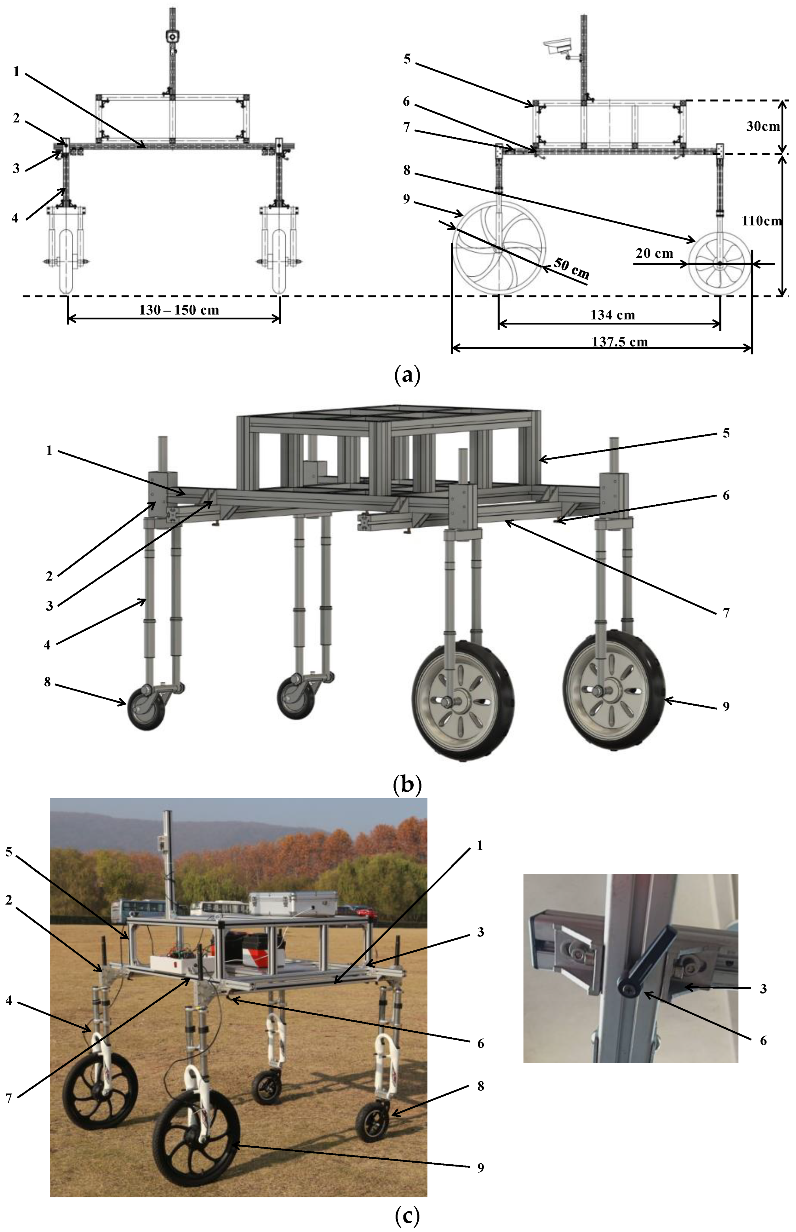
This article focused on disclosing the mechanical structure of a high-clearance robot chassis and demonstrated its application in wheat growth monitoring. Subsequent research will further consider using this chassis combined with AI technology to better realize smart functions such as automatic navigation and intelligent obstacle avoidance;
(2)
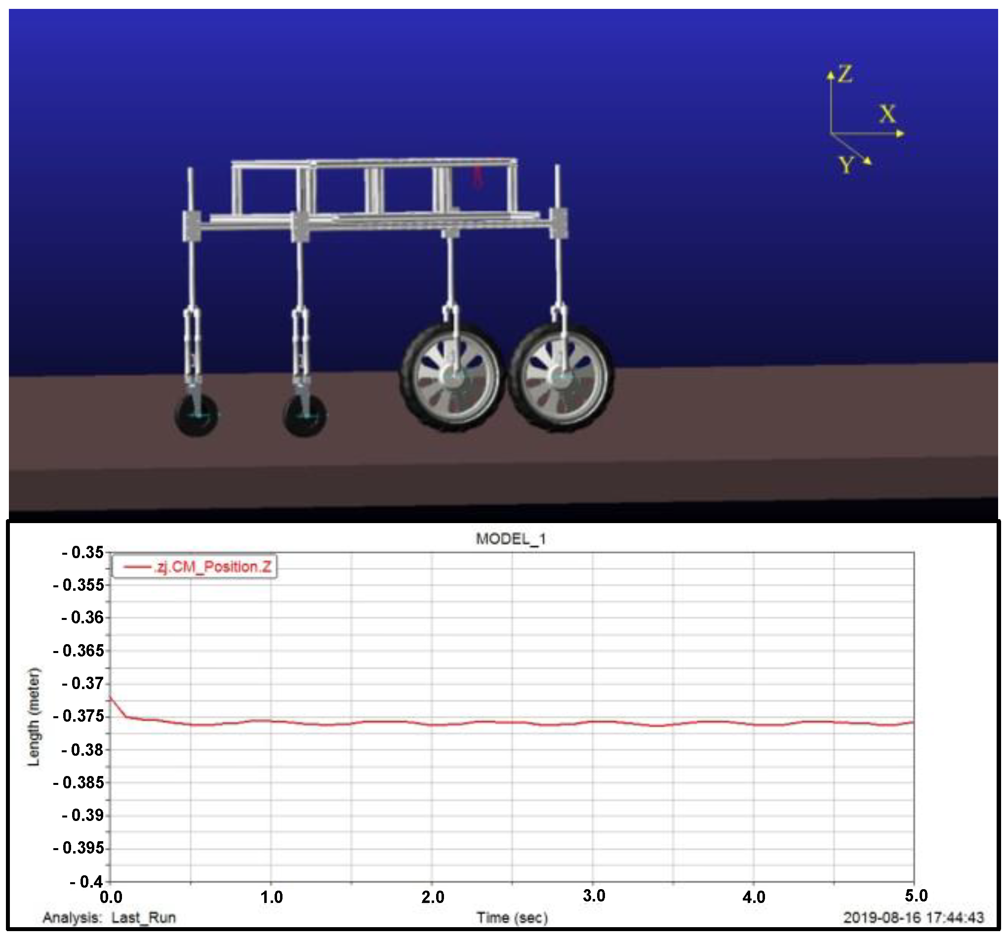
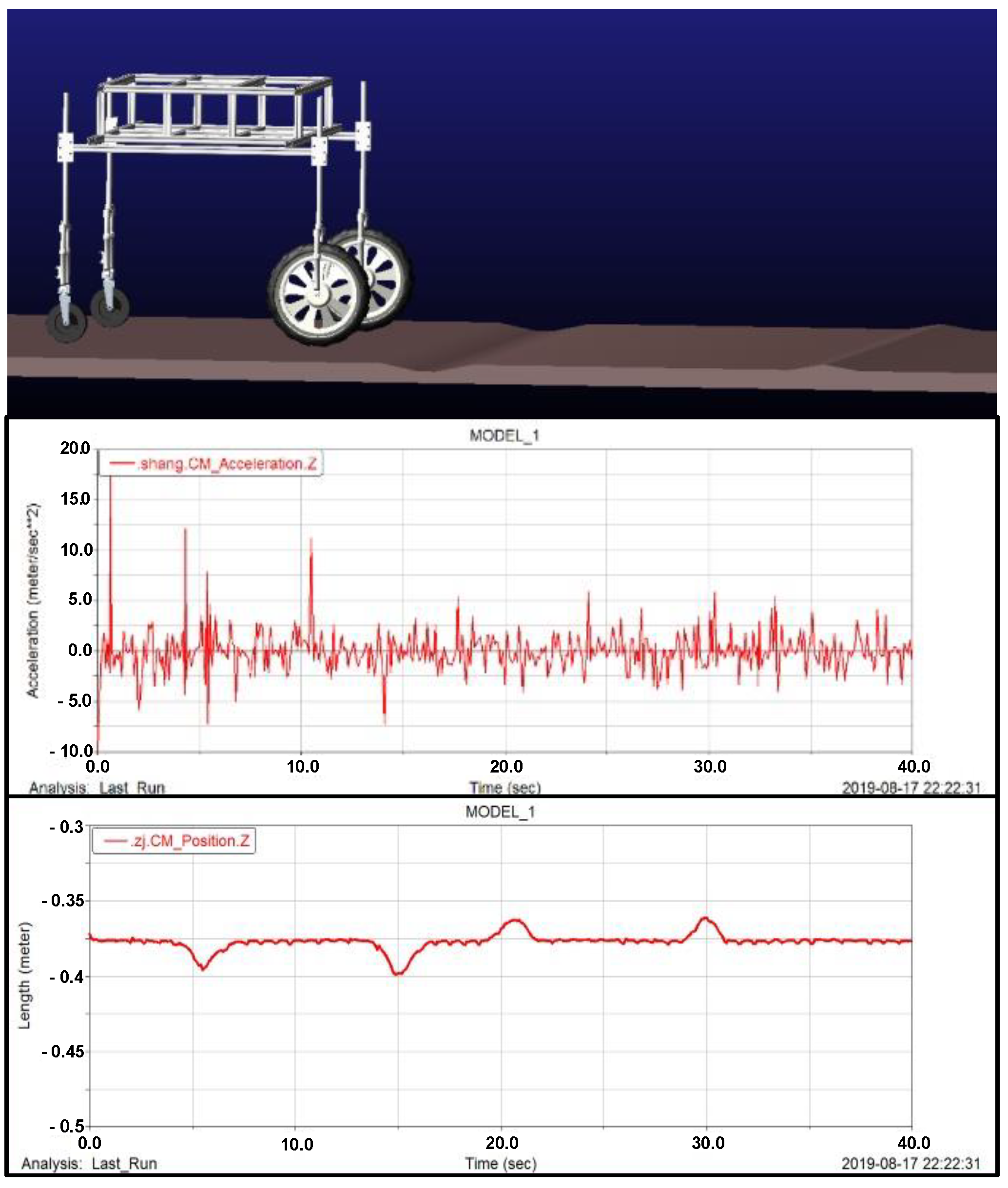
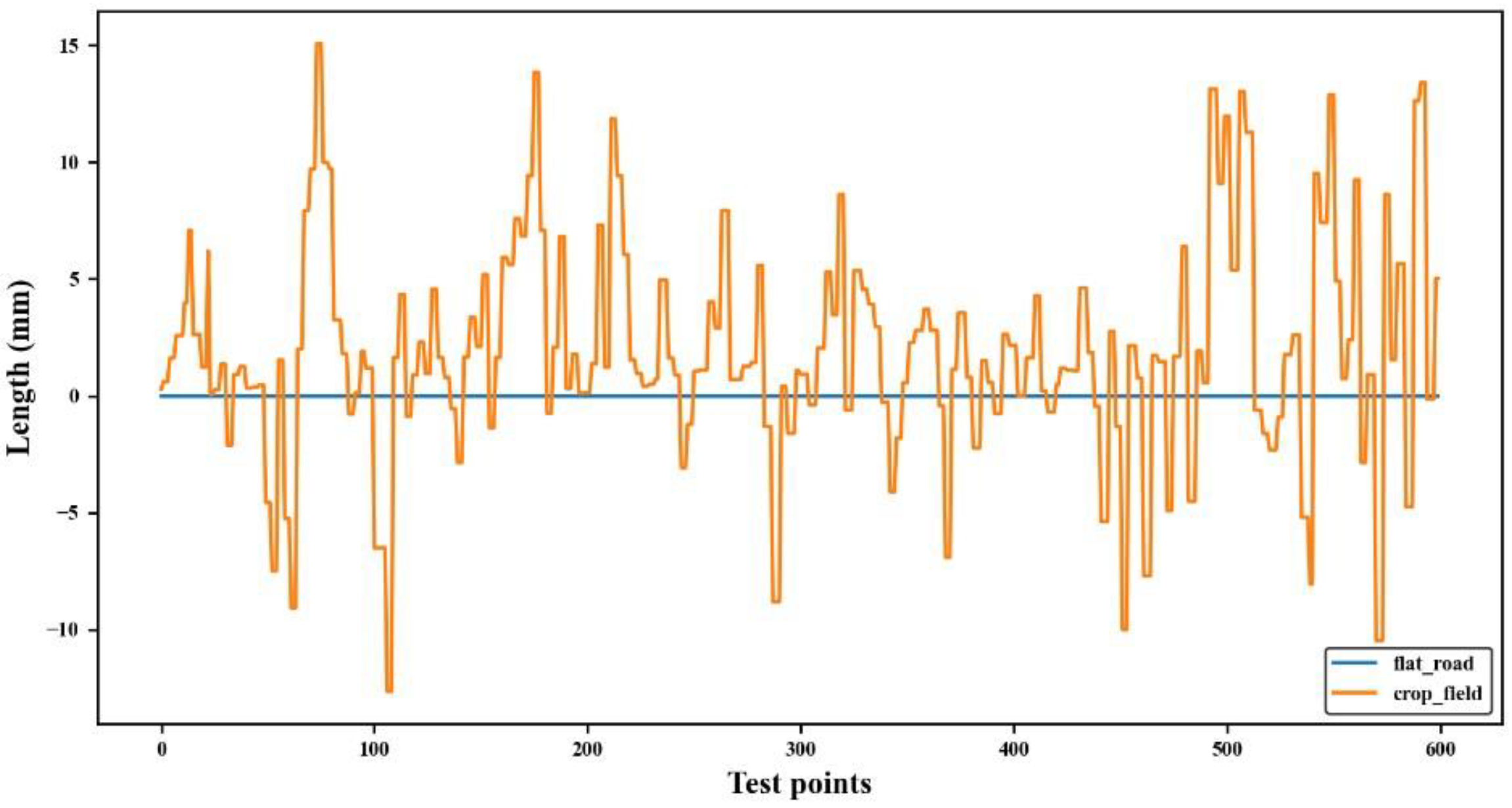
A model of the wheeled crop-growth-monitoring robot chassis was built in Pro/E based on the mechanical structural design. The kinematic stability was analyzed in Adams. According to the simulation results, the displacement of its mass center was smaller than 2 mm and the pitching angle stayed at 0° when the robot chassis was on flat pavement. When crossing obstacles (10 cm deep pits and 10 cm high bumps), the displacements along the body height direction were 1.78 cm and 1.46 cm, which were only 1.6% and 1.3% of the body height, respectively. The test results showed that the mass center remained unchanged when the wheeled robot chassis was running on flat pavement; during field operation, the maximum mass center displacement was 1.51 cm, which was only 1.3% of the body height. Thus, the wheeled robot chassis shows high operational stability;
(3)
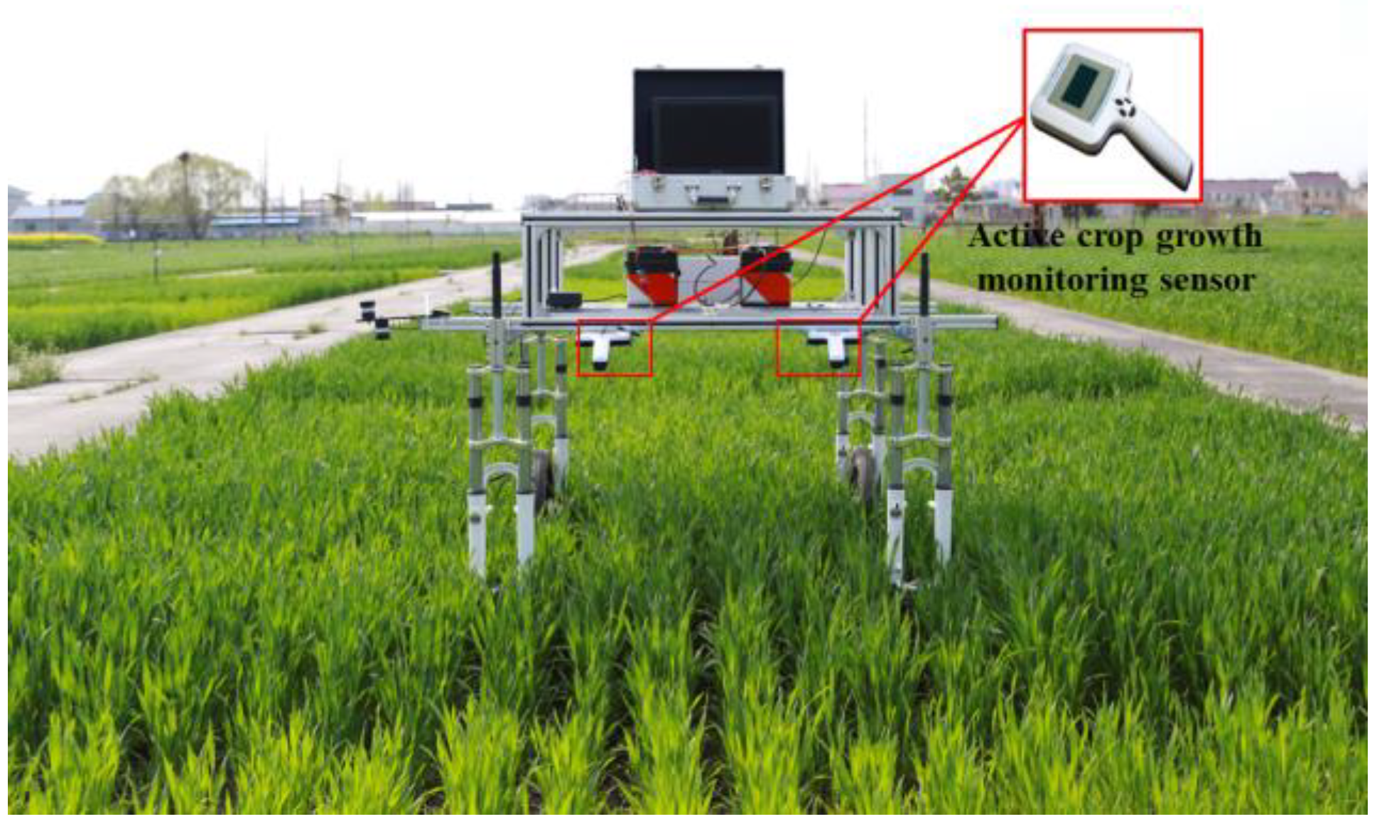
The motions of the wheeled crop-growth-monitoring robot chassis in the field were controlled by the self-developed LabVIEW upper-computer software platform. Functions such as the acquisition, analysis, display, and management of data collected from the environment information sensors and crop growth sensors are integrated into this software platform, which helped to overcome the shortcomings of separate operations between the robot chassis control system and the sensor test software and simplified the test flow;
(4)
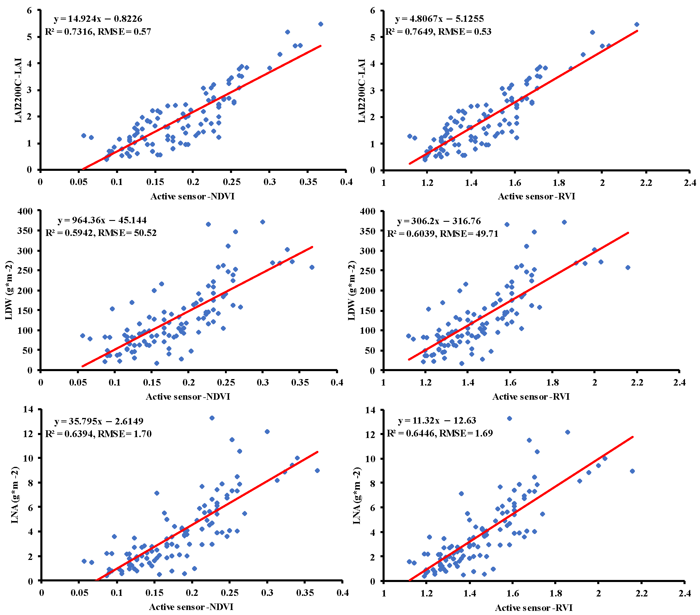
According to the tests, the NDVI and RVI obtained by the wheeled robot chassis were highly consistent with those obtained with the ASD FieldSpec HandHeld 2 spectrometer. The agronomic parameters suggest that the spectral vegetation indexes acquired by the wheeled robot chassis can favorably predict the LAI, LDW, and LNA of wheat. In conclusion, the proposed wheeled crop-growth-monitoring robot chassis can achieve stable, real-time, and accurate monitoring of wheat growth.

Author Contributions

Data curation, J.N.; funding acquisition, J.N.; investigation, L.Y., X.J. and W.C.; methodology, Y.Z. and J.N.; resources, J.N.; software, L.Y.; supervision, Y.Z.; validation, L.Y. and X.J.; writing—original draft, L.Y. and H.Y.; writing—review and editing, Y.Z., X.J., W.C. and J.N. All authors have read and agreed to the published version of the manuscript.

Funding

This research was funded by the National Key Research and Development Program of China (grant number 2021YFD2000101), Modern Agricultural Machinery Equipment & Technology Demonstration and Promotion of Jiangsu Province (grant number NJ2021-58), and the Primary Research & Development Plan of Jiangsu Province of China (grant number BE2021304).

Data Availability Statement

The data presented in this study are available upon reasonable request from the corresponding author.

Acknowledgments

We would like to thank all the people who helped with the field wheat management.

Conflicts of Interest

The authors declare no conflict of interest.

References

  1. Rogovska, N.; Laird, D.A.; Chiou, C.-P.; Bond, L.J. Development of field mobile soil nitrate sensor technology to facilitate precision fertilizer management. Precis. Agric. 2019, 20, 40–55. [Google Scholar] [CrossRef]
  2. Zhang, N.; Wang, M.; Wang, N. Precision agriculture—A worldwide overview. Comput. Electron. Agric. 2002, 36, 113–132. [Google Scholar] [CrossRef]
  3. Das, J.; Cross, G.; Qu, C.; Makineni, A.; Tokekar, P.; Mulgaonkar, Y.; Kumar, V. Devices, systems, and methods for automated monitoring enabling precision agriculture. In Proceedings of the 2015 IEEE International Conference on Automation Science and Engineering (CASE), Gothenburg, Sweden, 24–28 August 2015; pp. 462–469. [Google Scholar]
  4. Seelan, S.K.; Laguette, S.; Casady, G.M.; Seielstad, G.A. Remote sensing applications for precision agriculture: A learning community approach. Remote Sens. Environ. 2003, 88, 157–169. [Google Scholar] [CrossRef]
  5. Tang, Y.; Wang, R.; Huang, J. Relations between red edge characteristics and agronomic parameters of crops. Pedosphere 2004, 14, 467–474. [Google Scholar]
  6. Zhang, X.; Li, M.; Cui, D.; Zhao, P.; Sun, J.; Tang, N. New method and instrument to diagnose crop growth status in greenhouse based on spectroscopy. Eur. PubMed Cent. 2006, 26, 887–890. [Google Scholar]
  7. Bonfil, D.J. Wheat phenomics in the field by RapidScan: NDVI vs. NDRE. Isr. J. Plant Sci. 2017, 64, 41–54. [Google Scholar] [CrossRef]
  8. Lu, J.; Miao, Y.; Shi, W.; Li, J.; Wan, J.; Gao, X.; Zhang, J.; Zha, H. Using portable RapidSCAN active canopy sensor for rice nitrogen status diagnosis. Adv. Anim. Biosci. 2017, 8, 349–352. [Google Scholar] [CrossRef]
  9. Scharf, P.; Oliveira, L.; Vories, E.; Dunn, D.; Stevens, G. Crop sensors for variable-rate nitrogen application to cotton. In Proceedings of the ASA-CSSA-SSSA Annual Meeting, Columbia, CA, USA, 5–9 October 2008. [Google Scholar]
  10. Berni, J.A.; Zarco-Tejada, P.J.; Suárez, L.; Fereres, E. Thermal and narrowband multispectral remote sensing for vegetation monitoring from an unmanned aerial vehicle. IEEE Trans. Geosci. Remote Sens. 2009, 47, 722–738. [Google Scholar] [CrossRef]
  11. Jin, X.; Liu, S.; Baret, F.; Hemerlé, M.; Comar, A. Estimates of plant density of wheat crops at emergence from very low altitude UAV imagery. Remote Sens. Environ. 2017, 198, 105–114. [Google Scholar] [CrossRef]
  12. Schirrmann, M.; Giebel, A.; Gleiniger, F.; Pflanz, M.; Lentschke, J.; Dammer, K.-H. Monitoring agronomic parameters of winter wheat crops with low-cost UAV imagery. Remote Sens. 2016, 8, 706. [Google Scholar] [CrossRef]
  13. Sankey, T.; Donager, J.; McVay, J.; Sankey, J.B. UAV lidar and hyperspectral fusion for forest monitoring in the southwestern USA. Remote Sens. Environ. 2017, 195, 30–43. [Google Scholar] [CrossRef]
  14. Varco, J.; Fox, A.; Raper, T.; Hubbard, K. Development of sensor based detection of crop nitrogen status for utilization in variable rate nitrogen fertilization. In Precision Agriculture; Springer: Berlin/Heidelberg, Germany, 2013; pp. 145–150. [Google Scholar]
  15. Rosell Polo, J.R.; Sanz Cortiella, R.; Llorens Calveras, J.; Arnó Satorra, J.; Ribes Dasi, M.; Masip Vilalta, J.; Camp, F.; Gràcia, F.; Solanelles Batlle, F.; Pallejà Cabrè, T. A tractor-mounted scanning LIDAR for the non-destructive measurement of vegetative volume and surface area of tree-row plantations: A comparison with conventional destructive measurements. Biosyst. Eng. 2009, 102, 128–134. [Google Scholar] [CrossRef]
  16. Sudduth, K.; Kitchen, N.; Drummond, S. Comparison of three canopy reflectance sensors for variable-rate nitrogen application in corn. In Proceedings of the 10th International Conference on Precision Agriculture, Denver, CO, USA, 18–21 July 2010; pp. 18–21. [Google Scholar]
  17. Fernandez, M.G.S.; Bao, Y.; Tang, L.; Schnable, P.S. A high-throughput, field-based phenotyping technology for tall biomass crops. Plant Physiol. 2017, 174, 2008–2022. [Google Scholar] [CrossRef] [PubMed]
  18. Deery, D.; Jimenez-Berni, J.; Jones, H.; Sirault, X.; Furbank, R. Proximal remote sensing buggies and potential applications for field-based phenotyping. Agronomy 2014, 4, 349–379. [Google Scholar] [CrossRef]
  19. Lan, Y.; Zhang, H.; Lacey, R.; Hoffmann, W.; Wu, W. Development of an integrated sensor and instrumentation system for measuring crop conditions. Agric. Eng. Int. CIGR Ejournal 2009, 11, 1–16. [Google Scholar]
  20. Erdle, K.; Mistele, B.; Schmidhalter, U. Comparison of active and passive spectral sensors in discriminating biomass parameters and nitrogen status in wheat cultivars. Field Crops Res. 2011, 124, 74–84. [Google Scholar] [CrossRef]
  21. Beauchêne, K.; Leroy, F.; Fournier, A.; Huet, C.; Bonnefoy, M.; Lorgeou, J.; De Solan, B.; Piquemal, B.; Thomas, S.; Cohan, J.-P. Management and characterization of abiotic stress via PhénoField®, a high-throughput field phenotyping platform. Front. Plant Sci. 2019, 10, 904. [Google Scholar] [CrossRef]
  22. Virlet, N.; Sabermanesh, K.; Sadeghi-Tehran, P.; Hawkesford, M.J. Field Scanalyzer: An automated robotic field phenotyping platform for detailed crop monitoring. Funct. Plant Biol. 2017, 44, 143–153. [Google Scholar] [CrossRef]
  23. Susko, A.Q.; Gilbertson, F.; Heuschele, D.J.; Smith, K.; Marchetto, P. An automatable, field camera track system for phenotyping crop lodging and crop movement. HardwareX 2018, 4, e00029. [Google Scholar] [CrossRef]
  24. Baharav, T.; Bariya, M.; Zakhor, A. Computing height and width of in situ sorghum plants using 2.5 d infrared images. In Proceedings of the IS&T International Symposium on Electronic Imaging, Burlingame, CA, USA, 29 January–2 February 2017. [Google Scholar]
  25. Young, S.N.; Kayacan, E.; Peschel, J.M. Design and field evaluation of a ground robot for high-throughput phenotyping of energy sorghum. Precis. Agric. 2019, 20, 697–722. [Google Scholar] [CrossRef]
  26. Basu, S.; Omotubora, A.; Beeson, M.; Fox, C. Legal framework for small autonomous agricultural robots. AI Soc. 2020, 35, 113–134. [Google Scholar] [CrossRef]
  27. Dorhout, D. Ripe for Robots. Available online: https://www.cropscience.bayer.com/innovations/data-science/a/ripe-robots (accessed on 25 January 2023).
  28. Bai, G.; Ge, Y.; Hussain, W.; Baenziger, P.S.; Graef, G. A multi-sensor system for high throughput field phenotyping in soybean and wheat breeding. Comput. Electron. Agric. 2016, 128, 181–192. [Google Scholar] [CrossRef]
  29. Yuan, W.; Li, J.; Bhatta, M.; Shi, Y.; Baenziger, P.S.; Ge, Y. Wheat height estimation using LiDAR in comparison to ultrasonic sensor and UAS. Sensors 2018, 18, 3731. [Google Scholar] [CrossRef] [PubMed]
  30. White, J.W.; Conley, M.M. A flexible, low-cost cart for proximal sensing. Crop Sci. 2013, 53, 1646–1649. [Google Scholar] [CrossRef]
  31. Qiu, Q.; Sun, N.; Wang, Y.; Fan, Z.; Meng, Z.; Li, B.; Cong, Y. Field-based high-throughput phenotyping for Maize plant using 3D LiDAR point cloud generated with a “Phenomobile”. Front. Plant Sci. 2019, 10, 554. [Google Scholar] [CrossRef] [PubMed]
  32. Qiu, Q.; Fan, Z.; Meng, Z.; Zhang, Q.; Cong, Y.; Li, B.; Wang, N.; Zhao, C. Extended ackerman steering principle for the coordinated movement control of a four wheel drive agricultural mobile robot. Comput. Electron. Agric. 2018, 152, 40–50. [Google Scholar] [CrossRef]
  33. Shafiekhani, A.; Kadam, S.; Fritschi, F.B.; DeSouza, G.N. Vinobot and vinoculer: Two robotic platforms for high-throughput field phenotyping. Sensors 2017, 17, 214. [Google Scholar] [CrossRef] [PubMed]
  34. Weiss, U.; Biber, P. Plant detection and mapping for agricultural robots using a 3D LIDAR sensor. Robot. Auton. Syst. 2011, 59, 265–273. [Google Scholar] [CrossRef]
  35. Reina, G.; Vargas, A.; Nagatani, K.; Yoshida, K. Adaptive kalman filtering for gps-based mobile robot localization. In Proceedings of the 2007 IEEE International Workshop on Safety, Security and Rescue Robotics, Rome, Italy, 27–29 September 2007; pp. 1–6. [Google Scholar]
  36. Carpio, R.F.; Potena, C.; Maiolini, J.; Ulivi, G.; Rosselló, N.B.; Garone, E.; Gasparri, A. A navigation architecture for ackermann vehicles in precision farming. IEEE Robot. Autom. Lett. 2020, 5, 1103–1110. [Google Scholar] [CrossRef]
  37. Bangert, W.; Kielhorn, A.; Rahe, F.; Albert, A.; Biber, P.; Grzonka, S.; Haug, S.; Michaels, A.; Mentrup, D.; Hänsel, M. Field-robot-based agriculture: “RemoteFarming. 1” and “BoniRob-Apps”. VDI-Berichte 2013, 2193, 2. [Google Scholar]
  38. Yao, L.; Wu, R.; Wu, S.; Jiang, X.; Zhu, Y.; Cao, W.; Ni, J. Design and Testing of an Active Light Source Apparatus for Crop Growth Monitoring and Diagnosis. IEEE Access 2020, 8, 206474–206490. [Google Scholar] [CrossRef]
Figure 1. Schematic of the crop-growth-monitoring robot chassis.
Agronomy 13 03043 g001
Figure 2. Variation in plant height of different wheat varieties during the growth period.
Agronomy 13 03043 g002
Figure 3. Mechanical design of the wheeled robot chassis. (a). Plane size design. (b). 3D model. (c). Actual structure: 1. longitudinal beam; 2. vertical shaft device; 3. stiffener; 4. suspension fork; 5. chassis body structure; 6. wheelbase adjustment wrench; 7. stringer; 8. engaged wheel; 9. driving wheel.
Agronomy 13 03043 g003
Figure 4. Kinematic simulation of the wheeled robot chassis on flat pavement.
Agronomy 13 03043 g004
Figure 5. Simulation of the obstacle crossing of the wheeled robot.
Agronomy 13 03043 g005
Figure 6. The active light source crop-growth-monitoring sensor [38].
Agronomy 13 03043 g006
Figure 7. Installation diagram of the crop growth sensor.
Agronomy 13 03043 g007
Figure 8. Test plots (The field surrounded by the red outline).
Agronomy 13 03043 g008
Figure 9. Test results of mass center displacement along the body height.
Agronomy 13 03043 g009
Figure 10. Test results of NDVI and RVI of wheat over the whole growth period. The blue dots represent the test results, and the red line indicates the linear regression.
Agronomy 13 03043 g010
Figure 11. Wheat spectrum monitoring model for the robot chassis. The blue dots represent the test results, and the red line indicates the linear regression.
Agronomy 13 03043 g011
Disclaimer/Publisher’s Note: The statements, opinions and data contained in all publications are solely those of the individual author(s) and contributor(s) and not of MDPI and/or the editor(s). MDPI and/or the editor(s) disclaim responsibility for any injury to people or property resulting from any ideas, methods, instructions or products referred to in the content.

