Article

Design of an Adaptive Height Control System for Sugarcane Harvester Header

1
College of Mechanical Engineering, Guangxi University, Nanning 530000, China
2
Guangxi LiuGong Agricultural Machinery Co., Ltd., Liuzhou 545000, China
*
Author to whom correspondence should be addressed.
Agronomy 2024, 14(8), 1644; https://doi.org/10.3390/agronomy14081644
Submission received: 3 July 2024 / Revised: 25 July 2024 / Accepted: 25 July 2024 / Published: 26 July 2024

Abstract

:
This study addresses the issue of low control accuracy and harvesting efficiency resulting from the manual adjustment of the header height during the sugarcane harvesting process in hilly and mountainous regions. An adaptive header height adjustment system was designed and implemented. A test bench for the sugarcane harvester header was designed and constructed, incorporating a LiDAR to measure the ground height at the sugarcane growth point in front, and a draw-wire displacement sensor to monitor the real-time height of the header. I/O ports were allocated, and the control program was developed in the TIA Portal environment. The PLC control system achieves the precise adjustment of the cutting height based on the collected data. The experimental results indicate that the system can quickly respond and adjust the cutting height under complex terrain conditions. When the cutting height into the soil is 0 mm, the adaptive control system’s average cutting height error is 0.28 cm, and the average response time is 2.3 s. When the cutting depth into the soil is 2 cm, the average cutting height error is 0.21 cm, and the average response time is 2.31 s.

1. Introduction

Sugarcane, a significant economic crop, is primarily cultivated in regions such as Guangxi and Yunnan in China [1,2]. The terrain of sugarcane fields in these areas is predominantly hilly and mountainous, with a planting cycle that lasts three years [3]. The cutting height of current sugarcane harvesters predominantly relies on manual adjustment by drivers and cannot adaptively adjust to changes in the ground height. If the cutting height is too low, the blade may damage the root, and the excess soil can increase the impurity content of the sugarcane and the power consumption of the equipment, potentially leading to channel blockage and damage to the cutting mechanism. Conversely, if the cutting height is too high, it will result in harvest losses and an increased rate of breakage, making the incision susceptible to disease and insect infestations, thereby affecting the yield of the following year [4]. Therefore, the design and implementation of an adaptive height adjustment system for sugarcane harvesters is of great significance.
There are three primary types of header height control technologies: mechanical, electro-hydraulic, and sensor-based systems [5]. In foreign countries, the sugarcane cultivation areas are large, with small slopes and flat terrain, leading to a low demand for automatic cutting height control and relatively little research on this subject [6]. In China, sugarcane harvesters predominantly use mechanical header height control technology, which adjusts the header height via a parallel four-bar mechanism. This mechanical method requires the driver to manually adjust the header height according to field terrain changes, and the parallel four-bar mechanism performs poorly in terms of real-time profiling accuracy and control stability [7,8]. Currently, other header height control technologies are still under development. Liao et al. designed and installed an electro-hydraulic adaptive adjustment system on the 4LZ-1.2 tracked self-propelled combine harvester using infrared photoelectric sensors. However, the photoelectric sensors are susceptible to dust, weeds, and complex working environments, which result in inaccurate detection [9]. Zhang designed an automatic control system for the cutting height using ultrasonic sensors. The height is detected by ultrasonic sensors, and the position is measured by hydraulic cylinder displacement sensors. The microcontroller integrates this information to control the proportional directional valve, adjusting the height. However, ultrasonic sensors are prone to interference from crop residues, leading to a relatively low measurement accuracy and reliability [10]. Ni et al. designed a floating control system for the cutter head of a sugarcane harvester, adjusting the header height through an improved hydraulic system in conjunction with an angular displacement sensor, which remains only in the theoretical stage [11]. Wen et al. proposed a computer vision method to control the cutting height based on images captured by the camera, but the camera is susceptible to the lighting conditions [12]. In summary, the header height control technologies used by sugarcane harvesters in China cannot meet the actual production needs.
To address the inability of sugarcane harvesters to adaptively adjust the header height according to ground fluctuations, this study designs an adaptive header height adjustment system. This system utilizes a LiDAR and draw-wire displacement sensors for the real-time monitoring and collection of the ground height and cutting height data and employs adaptive electro-hydraulic control to manage ground changes, achieving real-time ground height monitoring and automatic header height control.

2. Materials and Methods

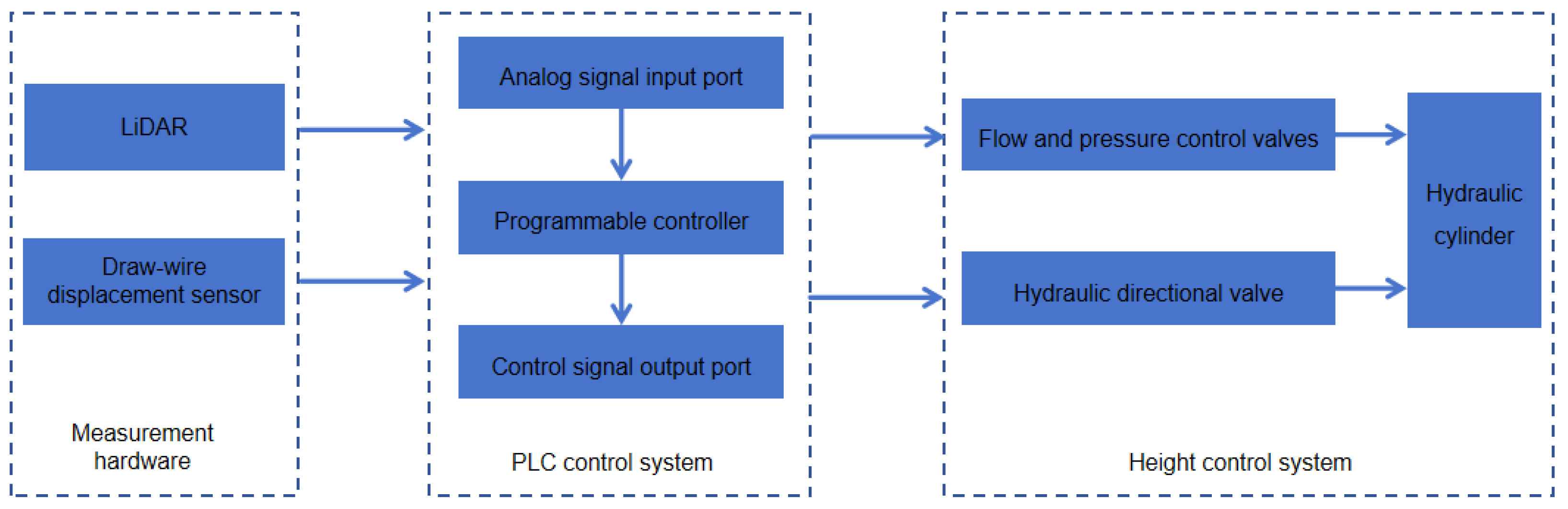
2.1. Overall System Structure

Figure 1 illustrates the ground information acquisition and electro-hydraulic system structure of the sugarcane harvester’s header height adaptive control system. The system primarily consists of height information acquisition sensors (LiDAR for ground height information and a displacement sensor for cutting height information), a PLC control system, and a hydraulic system. The PLC control system is connected to the input end of the ranging sensors, converting the analog signal transmitted by the sensor into a digital signal in real time for data reading. The output end, equipped with a relay, is connected to the hydraulic system, which adjusts the header height based on the control signal sent by the PLC control system.

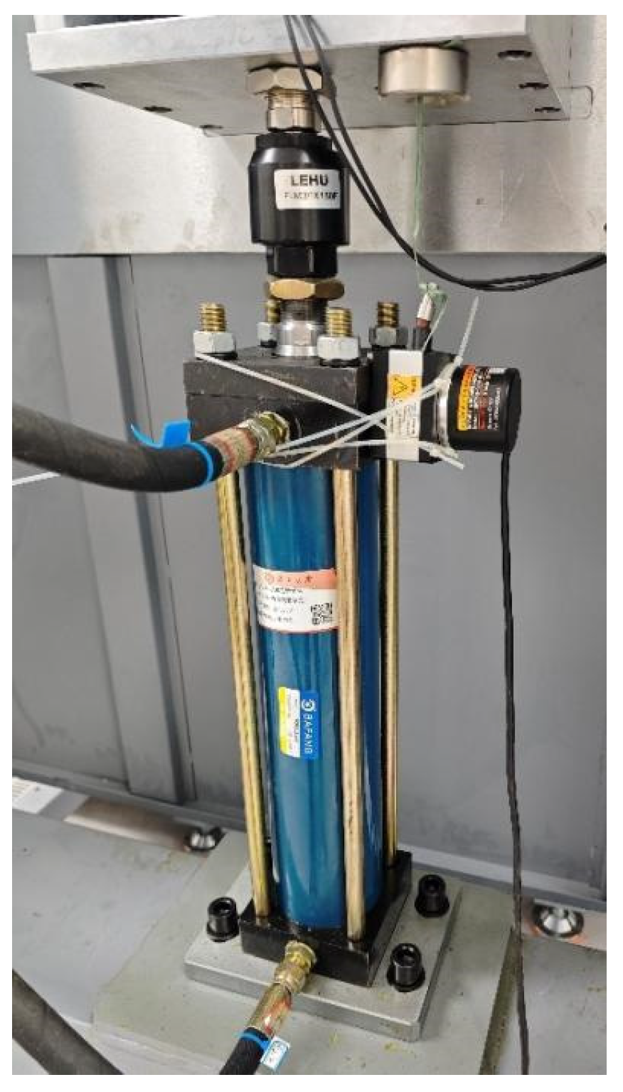
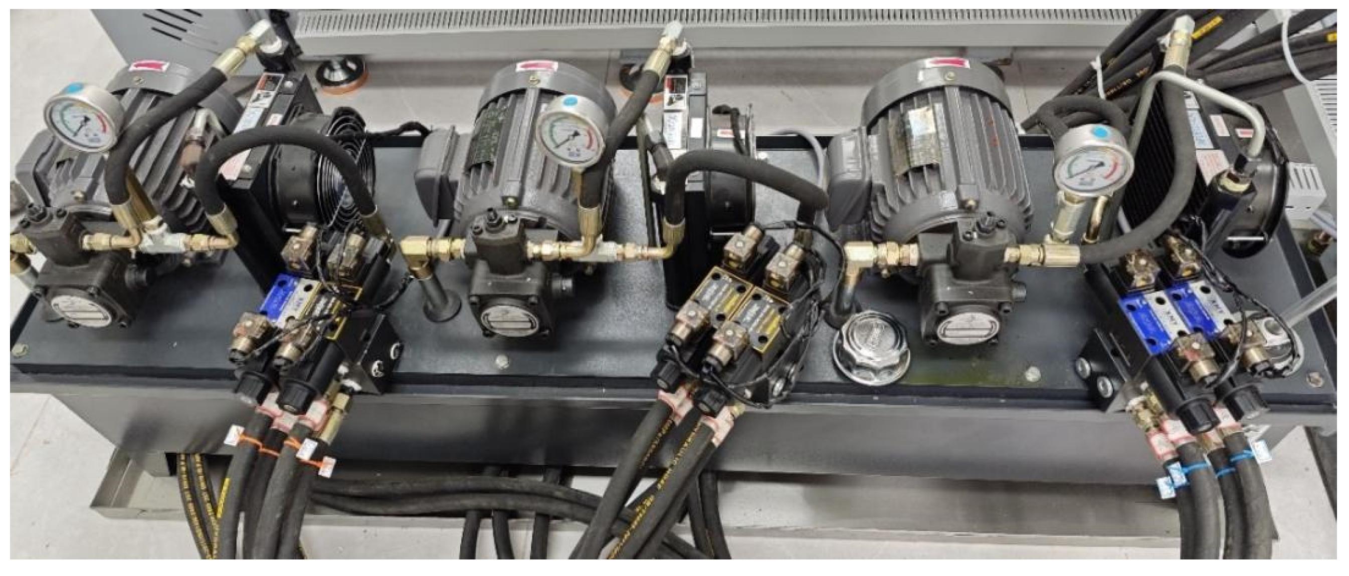
2.2. Design of Sugarcane Cutting Test Bench

To automatically adjust the sugarcane harvester’s header height according to ground undulations, achieve precise control of the header height, and conduct multiple experiments and adjustments without affecting actual production, thereby saving time and cost, a sugarcane harvester header height adaptive adjustment test bench was designed, as shown in Figure 2.
The test bench utilizes a gantry structure and is primarily composed of key components such as the lifting device, hydraulic system, control system, sugarcane fixing fixture, and chain conveyor line. By incorporating height information acquisition sensors, PLC control systems, and hydraulic systems, this test bench can collect real-time height data, process control signals, and adjust the header height. The functions and parameters of each component are listed in Table 1.
The design principle relies on the hydraulic system for power, driving the lifting device and cutting mechanism to achieve height adjustment. The control system monitors the operational status of various components and adjusts the cutting height for different terrains based on real-time height data collected by sensors. The sugarcane fixing fixture and chain conveyor line simulate the actual growth environment and harvesting process of sugarcane and transport the sugarcane to the cutting mechanism for processing.

2.3. Ground Height Detection

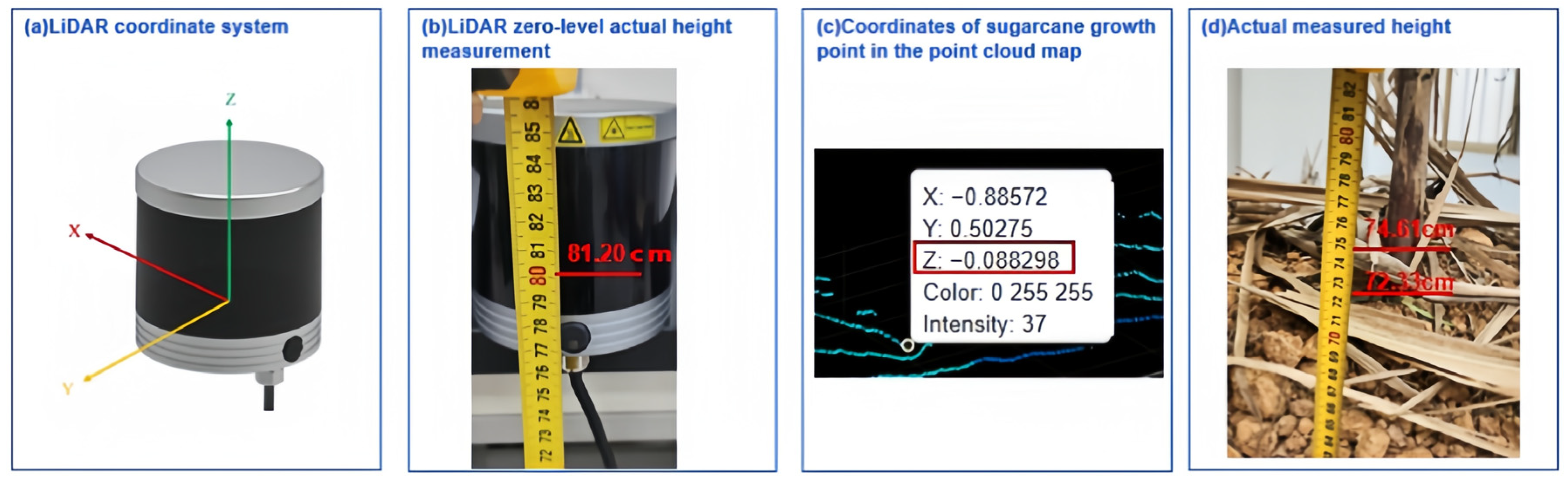
2.3.1. Data Acquisition

To simulate the actual working environment of the sugarcane harvester in single-row mode, the LiDAR was installed on a table on the left side of the test bench. To ensure that the indoor simulation experiment conditions are consistent with the sugarcane field experiment conditions, the LiDAR was installed at a height of 81.2 cm and a horizontal distance of 85 cm from the test bench. The LiDAR collects information at a frequency of 10 Hz. The layout and testing environment of the test bench are illustrated in Figure 3 and Figure 4.

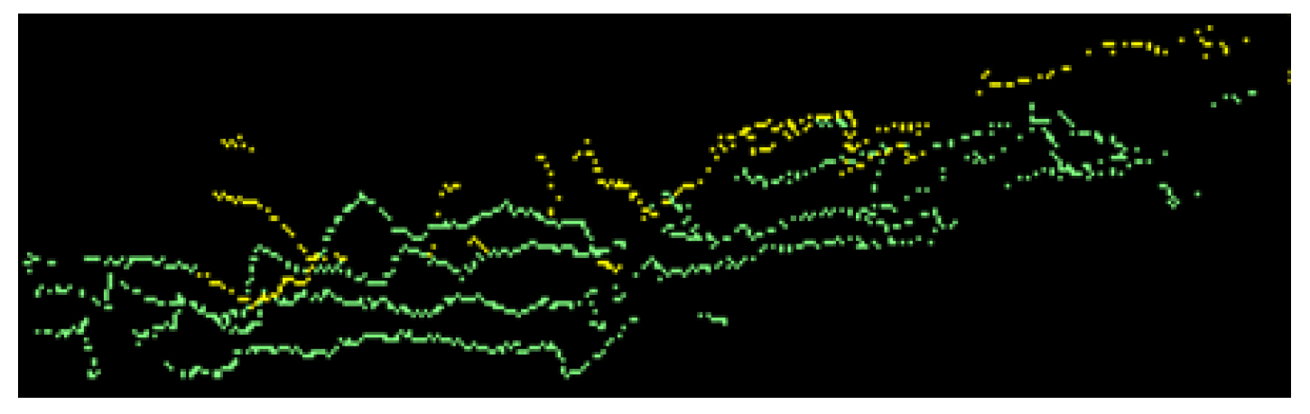
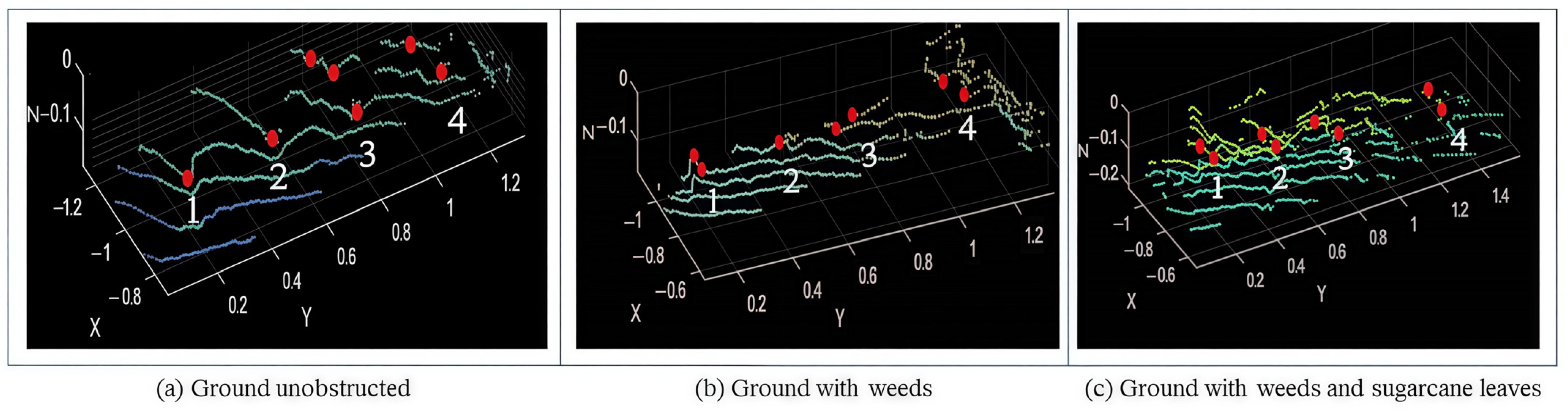
2.3.2. Terrain Inversion

When the ground is obstructed by obstacles such as sugarcane leaves and weeds, parts of the ground cannot be detected. The terrain inversion method is employed to restore terrain information in these obstructed areas, achieving the accurate reconstruction of the ground [13]. Cubic polynomial fitting is suitable for complex terrain due to its mathematical properties and flexibility, allowing it to accurately fit terrains with undulations and avoid overfitting or underfitting issues [14]. For ground points not obscured by sugarcane leaves, a cubic polynomial is used to fit point cloud data, generating a continuous ground surface model to capture terrain changes. Firstly, select a polynomial order of n=3 and apply the least squares method to fit the ground point data, resulting in the following cubic polynomial function:
P ( x , y ) = a 3 x 3 + a 2 x 2 + a 1 x + b 3 y 3 + b 2 y 2 + b 1 y + c
where a 3 , a 2 , a 1 , b 3 , b 2 , b 1 , and c are the fitting parameters, x and y represent the horizontal coordinates of the ground point, and P ( x , y ) represents the vertical coordinate of the ground points. Using the least squares method to determine the fitting parameters of the polynomial, a ground model of the occluded area can be generated.
Due to the obstruction of sugarcane leaves, the ground point cloud in Figure 5 cannot be accurately scanned or displayed, resulting in missing ground contours. Using cubic polynomial fitting, the occluded terrain was reconstructed, as shown in Figure 6, resulting in complete and continuous ground contours. Terrain inversion generates a smooth fitting curve by utilizing surrounding unobstructed ground point cloud data, reconstructing the originally missing terrain. The reconstructed terrain contours more accurately reflect the actual height and shape of the ground.

2.3.3. Identification of Sugarcane Growth Point Height

To identify the intersection point between the sugarcane and the ground, first set an initial minimum Z coordinate value and traverse each point in the sugarcane model to check if its Z coordinate value is less than the current recorded minimum value [15]. If so, update the current minimum Z coordinate value and record the point coordinate as the lowest point until all points are checked. The final lowest point obtained is the lowest point at the bottom of the sugarcane model. This lowest point is then projected onto the ground and marked on the ground point cloud, representing the intersection point between the sugarcane and the ground.

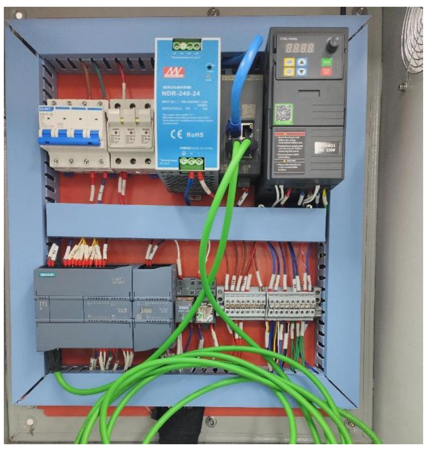
2.4. Control System Design

As shown in Figure 7, the PLC (Programmable Logic Controller) control system is responsible for the precise control and real-time adjustment of the hydraulic system in the height adaptive control of the sugarcane harvester header. The LiDAR collects terrain height data, and Figure 8 shows the draw-wire displacement sensor fixed on the lifting hydraulic cylinder of the header, which collects data on the height of the test bench. When the header rises or falls, it drives the rope to stretch and retract. The PLC analyzes and processes the collected data through its internal structure, ultimately transmitting the calculation results to the hydraulic valve. The hydraulic valve then controls the opening, closing, and reversing of the hydraulic pipeline, achieving the adaptive adjustment of the cutting height to the ground height. The hydraulic system is shown in Figure 9.

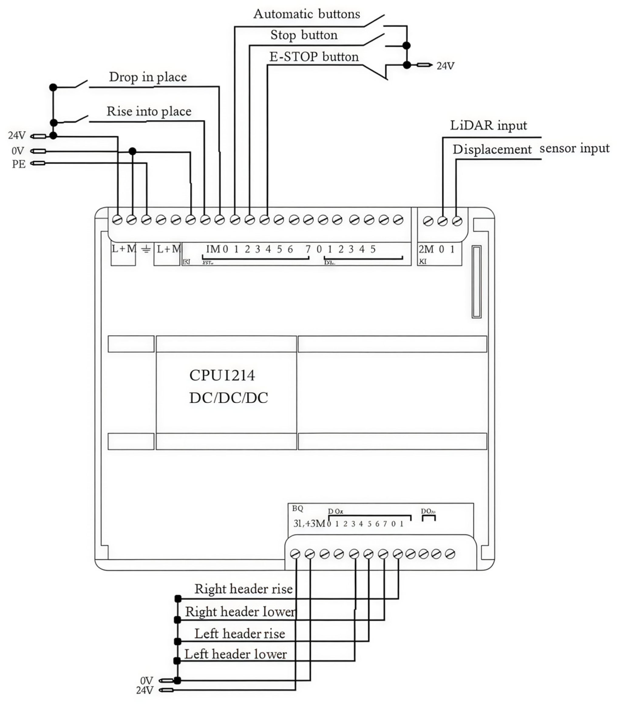
2.4.1. I/O Port Allocation

A Siemens CPU 1214C DC/DC/DC, sourced from Siemens in Munich, Germany, is chosen as the main controller, featuring 14 digital input interfaces and 10 digital output interfaces. The digital inputs (DIs) and outputs (DQs), represented as 1 and 0, respectively, are used to control the start and stop of the actuator. These control signals manage the on/off states of hydraulic valves by altering their closed and open states, thereby controlling the on/off and reversing of oil circuits.
The PLC is also equipped with two analog input ports (AIs) to receive continuous signals from the external sensors [16]. In this system, the signals for the rise and fall of the header are digital. The LiDAR measures the ground height, and the changes in the length of the wire in the draw-wire displacement sensor reflect the changes in the header height as analog signals.
The control module is powered by a 24 V power supply, with external power supply terminals labeled L and N. The inputs and outputs (I/O) allocation of the PLC in this system is shown in Table 2.
The PLC wiring diagram for the sugarcane harvester cutting header test bench is shown in Figure 10.

2.4.2. Data Acquisition and Processing

The draw-wire displacement sensor is installed on the lifting oil cylinder on both sides of the cutting header, measuring the real-time height of the cutting header via the displacement of the wire. The data measured by the sensor are voltage signals that need to be converted into analog signals via the analog input interface before the PLC can process them.
(1) The analog address of the sensor input to the PLC is IW64, and the data type is INT (integer type), representing the current header height analog signal [17].
(2) Conversion of voltage signal into analog signal: V analog = V Input × 10 24 .
(3) Conversion of analog signal into integer type: Current   height   analog = int ( V analog ) .
The ground height data collected by the LiDAR are transmitted to the PLC through a communication interface, representing the simulated ground height ahead. The ground height data are stored in the PLC’s analog input register, with the analog address being IW100 and the data type being INT.

2.4.3. Design of Cutting Header Height Control Logic

The header height control program is illustrated in Figure 11. “Header up 1” and “Header up 2” represent the upward movement of the left and right headers, while “Header down 1” and “Header down 2” represent their downward movement. To ensure safe and reliable control, the program for raising and lowering the header height is designed in interlock mode [18].
In the control logic, comparison instructions are introduced to compare the current header height with the front ground height measured by the LiDAR to determine the operation of the cutting header.
Δ h = h g h c
where h g is the ground height measured by the LiDAR, and h c is the header height measured by the draw-wire displacement sensor.
If Δ h > 0 , it indicates that the cutting header is lower than the ground and needs to be raised. The PLC will output a signal to Q0.0 or Q0.2 to control the corresponding hydraulic valve to rise.
If Δ h > 0 , it indicates that the cutting header is above the ground and needs to be lowered. The PLC will output a signal to Q0.1 or Q0.3 to control the corresponding hydraulic valve to lower.
If Δ h > 0 , it indicates that the current height is appropriate, and the PLC will not make any adjustments.

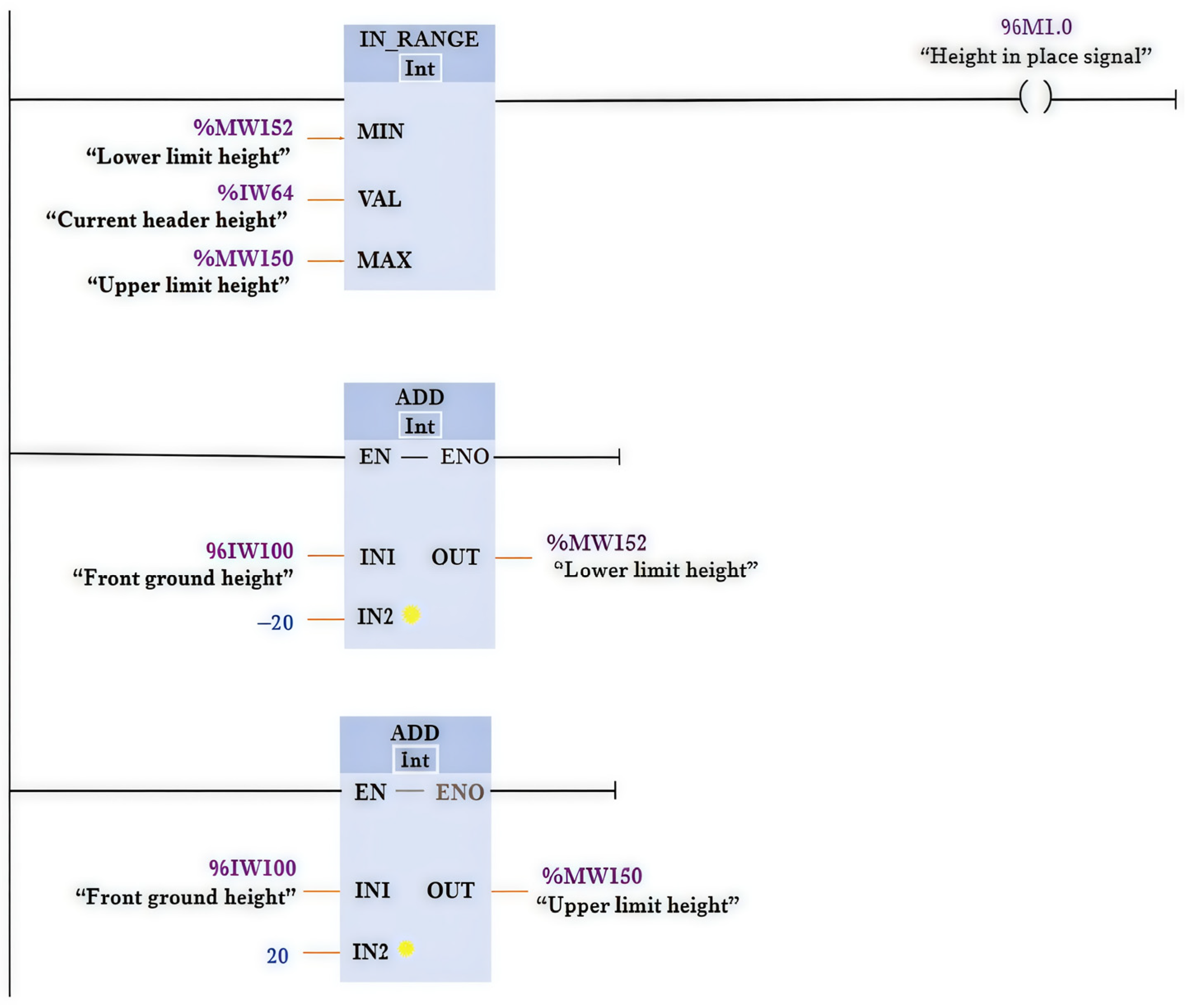
2.4.4. Target Height Error Range Program

The height adjustment of the sugarcane harvester cutting header test bench utilizes a hydraulic control system. Unlike motor control, hydraulic control makes it difficult to achieve the precise control of each analog signal. The program that determines the current height and the front ground height can achieve the stop of the header. However, due to the inertia of the hydraulic system, the current height’s analog signal may slightly exceed the front ground height [19]. In theory, the cutting header should stop at this point, but the system will issue a descent command, and the PLC executes the lowering operation. Due to inertia, the current height analog signal may be lower than the ground height ahead, prompting the PLC to immediately execute the raising command.
This repetition can cause the header to oscillate near the target height, leading to unsatisfactory control effects. Therefore, it is necessary to introduce a program for the target height error range so that when the cutting header reaches the specified height range, the PLC no longer executes up or down commands, thus achieving more stable control. The program for the target height error range is illustrated in Figure 12.
The meaning of this program is that once the current height analog signal reaches the error range of the target height, the PLC sends a height-in-place signal to the up and down commands. As the normally closed contacts of the height-in-place signal are connected in series within the header lifting and lowering program, once the PLC sends the height-in-place signal, both the raising and lowering commands will stop, achieving adaptive height adjustment.

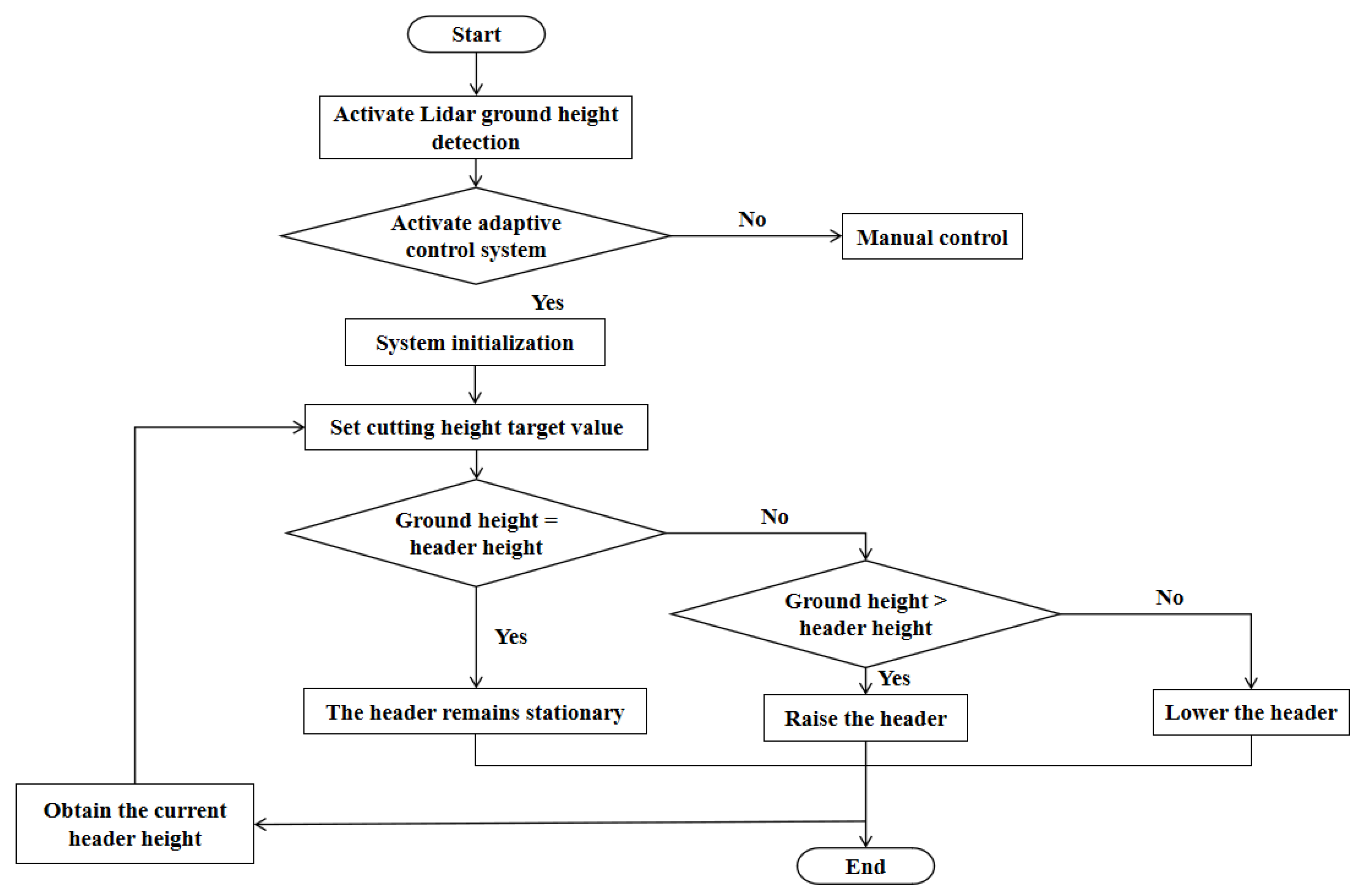
2.4.5. Cutting Height Adaptive Control Process

The workflow of the adaptive control system for the cutting header of the sugarcane harvester test bench is illustrated in Figure 13.
When the test bench for the sugarcane harvester header is ready to operate, the system first activates the LiDAR ground height detection function. The operator can choose to activate the cutting height adaptive control system. If not activated, the system enters manual operation mode. If activated, the control system initializes and sets the target cutting height. If the ground height exceeds the cutting header height, the system issues a raise command, and the header rises. If the ground height is less than the header height, the system will issue a descent command, and the header will descend.

3. Results and Discussion

3.1. Ground Height Acquisition with LiDAR

Figure 14 illustrates the effect of terrain inversion. The red dots indicate the boundary points between the sugarcane and the ground. As shown in the figure, the ground point cloud forms continuous linear structures that represent the ground contours.
To verify the accuracy of terrain inversion and ground height recognition, a comparative analysis was conducted between the ground height obtained from terrain inversion and the actual ground height in the presence of weeds and sugarcane leaves on the ground.
The LiDAR was fixed and placed at a height of 81.2 cm, with this set as the zero-horizontal plane. According to Figure 15c, the boundary point between the sugarcane and the ground identified by the LiDAR is located 8.83 cm below the zero-level plane, so its corresponding actual height is 72.37 cm. To verify this result, a measurement tool was used to measure the actual ground height at the same sugarcane growth point. As shown in Figure 15d, the height obstructed by sugarcane leaves was 74.61 cm, and the actual ground height was approximately 72.33 cm.
To further quantify the effectiveness of terrain inversion, a detailed comparison was conducted between the actual measured ground height, the height obstructed by sugarcane leaves and weeds, and the height before and after terrain inversion. The specific results are presented in Figure 16. When comparing the position height of the terrain inversion point cloud map with the actual measurement height, the error range was within ±0.17 cm, with an average error of 0.09 cm. These results indicate that LiDAR height recognition has high accuracy.

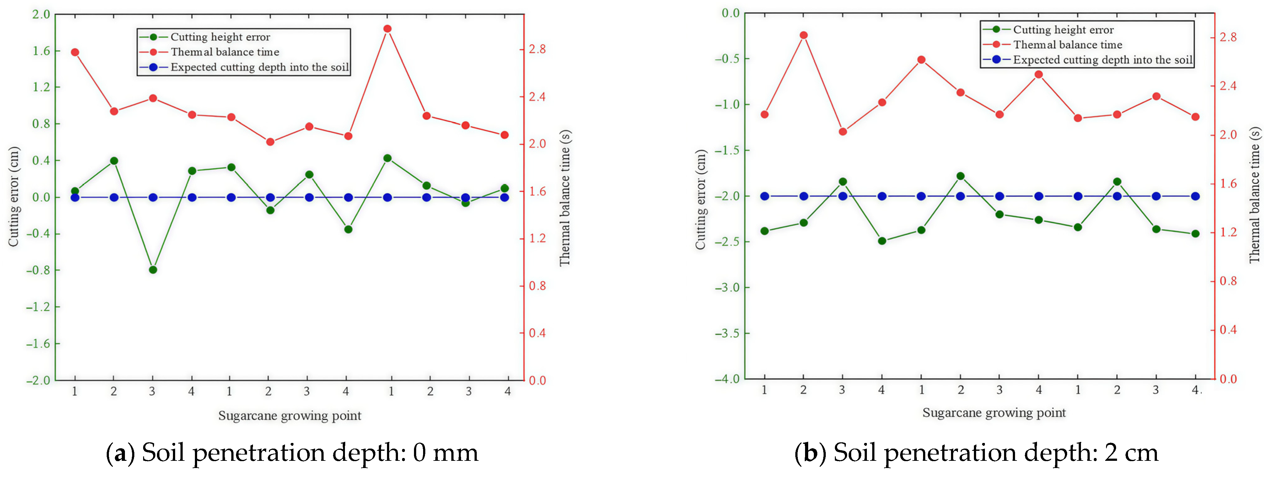
3.2. Control Accuracy

To assess the reliability and control accuracy of the adaptive control system for the header of the sugarcane harvester test bench, indoor sugarcane harvesting experiments were conducted at Guangxi University. Three ground points with varying levels of obstruction in the sugarcane growth area were selected as measurement points, with the harvesting speed set to 1.5 km/h. The cutting height of the header was measured, and the response time was recorded to evaluate the performance of the header height adaptive adjustment system.
When the average absolute error of the system is less than 0.7 cm, the error can be considered acceptable [20]. The experimental results are shown in Table 3 and Table 4, with the deviation being the difference between the actual cutting height and the set height.
The experimental results in Figure 17 indicate that when the soil penetration depth is set to 0 cm, the average cutting height error of the adaptive control system is 0.28 cm, with an average response time of 2.3 s. With a soil penetration depth of 2 cm, the average cutting height error is 0.21 cm, and the average response time is 2.31 s. Across different excavation depths and ground obstructions, the above height errors are within a reasonable range, meeting practical usage requirements.

3.3. Discussion

This study’s innovation lies in addressing the terrain adaptability and height adjustment issues of sugarcane harvesters by proposing a comprehensive solution based on LiDAR and draw-wire displacement sensors, achieving precise control through a PLC control system. However, this paper still has some shortcomings that need to be addressed, mainly in the following aspects:
(1) The collection of ground height data can be further improved by integrating multiple methods such as LiDAR, laser rangefinder, and machine vision to obtain data.
(2) The control system has not yet been integrated into an actual sugarcane harvester and has only been tested on the constructed test bench.
(3) Due to hardware limitations, control algorithms have not been integrated, preventing a more precise adjustment of the header height by controlling the hydraulic valve opening. In the future, an expansion module with analog output can be introduced, allowing for the integration of control algorithms such as fuzzy PID (Proportional Integral Derivative) and MPC (Model Predictive Control). These algorithms can be programmed based on the expansion module to achieve more accurate and efficient hydraulic valve control [21,22].

4. Conclusions

This study aims to resolve the challenges of low control accuracy and harvesting efficiency resulting from manual header height adjustments in sugarcane harvesters. A height adaptive adjustment system for the sugarcane harvester header test bench was designed and implemented to enhance the precision and efficiency.
(1) A height adaptive adjustment test bench for the sugarcane harvester header was designed and constructed. It integrates critical components such as the tilting mechanism, electro-hydraulic control system, clamping device, and chain conveyor line. The bench simulated the terrain changes and sugarcane growth status in actual operations, providing convenience for testing in different scenarios.
(2) A ground height extraction method based on LiDAR has been proposed. Data were collected from sugarcane fields under different conditions, such as with sugarcane leaves and weeds on the test bench. The obstructed ground was reconstructed using terrain inversion, and the ground height at the sugarcane growth points was obtained based on the 3D coordinates of the point cloud. The average error between the terrain inversion point cloud heights and the actual measured heights was verified to be 0.09 cm, providing reliable data support for the adaptive adjustment of the header height.
(3) Developed an automatic header height adjustment system. The I/O ports were allocated, and control programs were designed and written in the TIA Portal development environment. The experimental results demonstrated that the designed adaptive adjustment system could quickly respond and accurately adjust the header height under complex terrain conditions. When the soil penetration depth is 0 mm, the average height error of the adaptive control system is 0.28 cm, with an average response time of 2.3 s. At a soil penetration depth of 2 cm, the average cutting height error is 0.21 cm, with an average response time of 2.31 s.

Author Contributions

Conceptualization, Y.L. and M.S.; methodology, M.S. and J.W.; software, L.L.; validation, Y.L. and Y.P.; formal analysis, L.L. and J.W.; investigation, Y.P.; resources, Y.L.; data curation, L.L.; writing—original draft preparation, M.S.; writing—review and editing, M.S.; visualization, M.S.; supervision, Y.L.; project administration, Y.P.; funding acquisition, Y.L., Y.P. and J.W. All authors have read and agreed to the published version of the manuscript.

Funding

This research was funded by the National Key Research and Development Program of China (2022YFD2301100), Guangxi Major Science and Technology Special Fund of China (Guike AA22117007, Guike AA22117005), and Beihai Science and Technology Development Plan Project of China (2023174001).

Data Availability Statement

The data presented in this study are available upon request to the first author. The data are not publicly available due to privacy.

Conflicts of Interest

Author Yingchun Pan was employed by the company Guangxi LiuGong Agricultural Machinery Co., Ltd. The remaining authors declare that the research was conducted in the absence of any commercial or financial relationships that could be construed as a potential conflict of interest.

References

  1. López-Ortega, M.G.; Guadalajara, Y.; Junqueira, T.L.; Sampaio, I.L.; Bonomi, A.; Sánchez, A. Sustainability analysis of bioethanol production in Mexico by a retrofitted sugarcane industry based on the Brazilian expertise. Energy 2021, 232, 121056. [Google Scholar] [CrossRef]
  2. Omprakash, S. Assessment of sugarcane industry: Suitability for production, consumption, and utilization. Ann. Agrar. Sci. 2018, 16, 389–395. [Google Scholar]
  3. Wang, Z. Mechanism Research and Design Simulation of Soil Cutting Control for Sugarcane Harvesters. Master’s Thesis, Guangxi University, Nanning, China, 2014. [Google Scholar]
  4. Bai, J.; Ma, S.; Yang, G.; Wang, F.; Xing, H.; Ke, W. Testing and Analysis of the Extractor of a Sugarcane Chopper Harvester. Trans. ASABE 2020, 63, 251–257. [Google Scholar] [CrossRef]
  5. Ding, Z.; Ma, S.; Wang, F.; Xing, H.; Bai, J.; Hu, J. Development and Testing of an Electro-Hydraulic System for Height Control of Sugarcane Harvester Basecutter. J. ASABE 2022, 65, 305–312. [Google Scholar] [CrossRef]
  6. Mantovani, E.C.; Oliveira, P.E.B.; Queiroz, D.M.; Fernandes, A.L.T.; Cruvinel, P.E. Current status and future prospect of theagricultural mechanizationin Brazil. Agric. Mech. Asia Afr. Lat. Am. 2019, 50, 20–22. [Google Scholar]
  7. Zhao, L.; Zhang, J.; Jiao, S.; Zheng, T.; Li, J.; Zhao, T. Ground surface detection method using ground penetrating radar signal for sugarcane harvester base-cutter control. Biosyst. Eng. 2022, 219, 103–123. [Google Scholar] [CrossRef]
  8. Jian, Z.; Li, G.; Zhao, S.; Ma, C. Simulated experimental study on the automatic adjustment system of sugarcane harvester header height. J. Southwest Univ. (Nat. Sci. Ed.) 2018, 40, 12–18. [Google Scholar]
  9. Liao, Y.; Xiang, Y.; Wu, M.; Liu, D.; Chen, Y.; Li, Y. Design and testing of an adaptive height adjustment system for combine harvesters. J. Hunan Agric. Univ. 2018, 44, 326–329. [Google Scholar]
  10. Zhang, C. Research on Crop Height Measurement Method and Crop Profile Modeling of Harvester Cutting Platform. Master’s Thesis, Southeast University, Nanjing, China, 2019. [Google Scholar]
  11. Ni, Y.; Jin, C.; Chen, M.; Yuan, W.; Qian, Z.; Yang, T.; Cai, Z. Computational model and adjustment system of header height of soybean harvesters based on soil-machine system. Comput. Electron. Agric. 2021, 183, 105907. [Google Scholar] [CrossRef]
  12. Wen, J.; Yin, Y.; Zhang, Y.; Pan, Z.; Fan, Y. Detection of Wheat Lodging by Binocular Cameras during Harvesting Operation. Agriculture 2023, 13, 120. [Google Scholar] [CrossRef]
  13. Hu, X.; Wei, X.; Sun, J. A Noising-Denoising Framework for Point Cloud Upsampling via Normalizing Flows. Pattern Recognit. 2023, 140, 109569. [Google Scholar] [CrossRef]
  14. Wen, G.; Zhang, H.; Guan, Z.; Wei, S.; Jia, D. Bilateral filter denoising of Lidar point cloud data in automatic driving scene. Infrared Phys. Technol. 2023, 131, 104724. [Google Scholar]
  15. Deng, S.; Xu, Q.; Yue, Y.; Jing, S.; Wang, Y. Individual tree detection and segmentation from unmanned aerial vehicle-LiDAR data based on a trunk point distribution indicator. Comput. Electron. Agric. 2024, 218, 108717. [Google Scholar] [CrossRef]
  16. Chen, M.; Zhai, X.; Zhang, H.; Yang, R.; Wang, D.; Shang, S. Study on control strategy of the vine clamping conveying system in the peanut combine harvester. Comput. Electron. Agric. 2020, 178, 105744. [Google Scholar] [CrossRef]
  17. Chen, L.; Guo, Y. Design of the Distributed Control System Based on CAN Bus. Comput. Inf. Sci. 2011, 4, 83. [Google Scholar] [CrossRef]
  18. Zeng, L.; Du, H.; Ye, X.; Huang, J.; Chen, C.; Chen, X.; Ding, J. Research and experiments on low throttle loss switched inertance hydraulic systems based on inertive elements. Energy 2023, 283, 129073. [Google Scholar] [CrossRef]
  19. Robles-Durazno, A.; Moradpoor, N.; McWhinnie, J.; Russell, G.; Maneru-Marin, I. PLC memory attack detection and response in a clean water supply system. Int. J. Crit. Infrastruct. Prot. 2019, 26, 100300. [Google Scholar] [CrossRef]
  20. Gong, Y.; Jin, Z.; Bai, X.; Wang, S.; Wu, L.; Huang, W. Design and Experiment of the Cutter Bar Follow-up Control System for Sugarcane Harvester. J. Agric. Mach. 2023, 54, 119–128. [Google Scholar]
  21. Borase, R.P.; Maghade, D.K.; Sondkar, S.Y.; Pawar, S.N. A review of PID control, tuning methods and applications. Int. J. Dyn. Control 2021, 9, 818–827. [Google Scholar] [CrossRef]
  22. Jin, Z.; Gong, M.; Zhao, D.; Zhang, Y.; Liu, W.; Zhu, J.; Su, B. MPC motion control of boom descending of unmanned excavator based on regenerative valve. Heliyon 2024, 10, e29915. [Google Scholar] [CrossRef] [PubMed]
Figure 1. Structure diagram of ground information acquisition and electro-hydraulic control system.
Agronomy 14 01644 g001
Figure 2. Sugarcane cutting test bench. 1. Sugarcane conveyor line; 2. Sugarcane root fixing fixture; 3. Sugarcane; 4. Control box; 5. Lifting guide rail; 6. Cutting header; 7. Oil pipe; 8. Tilting mechanism; 9. Hydraulic system; 10. Lifting oil cylinder; 11. Support base.
Agronomy 14 01644 g002
Figure 3. Layout of test bench.
Agronomy 14 01644 g003
Figure 4. Experimental environment setup. (a) Ground without obstruction; (b) ground with weeds; (c) ground with weeds and sugarcane leaves.
Agronomy 14 01644 g004
Figure 5. Sugarcane leaves obstruction.
Agronomy 14 01644 g005
Figure 6. Terrain inversion.
Agronomy 14 01644 g006
Figure 7. PLC control system.
Agronomy 14 01644 g007
Figure 8. Data acquisition of draw-wire displacement sensor.
Agronomy 14 01644 g008
Figure 9. Hydraulic system.
Agronomy 14 01644 g009
Figure 10. PLC wiring diagram.
Agronomy 14 01644 g010
Figure 11. Logic design of cutting header height control.
Agronomy 14 01644 g011
Figure 12. Design of target height error range program.
Agronomy 14 01644 g012
Figure 13. Workflow of cutting height adaptive control system.
Agronomy 14 01644 g013
Figure 14. Terrain inversion point cloud.
Agronomy 14 01644 g014
Figure 15. Measurement of sugarcane growth point height in simulation experiment.
Agronomy 14 01644 g015
Figure 16. Height error statistics for sugarcane growth points.
Agronomy 14 01644 g016
Figure 17. Cutting error and response time at different soil penetration depths.
Agronomy 14 01644 g017
Table 1. Essential components and parameters of the experimental platform.
ComponentsParameters
Gantry main frameOverall dimensions: length 7.5 m, width 1.5 m
Load: 1200 kg
Material: carbon steel Q235A
Lifting deviceMaximum load: 2000 kg
Cylinder diameter: 80 mm
Maximum stroke: 300 mm
Tilting mechanismTilt angle: −15°~+15°
Hydraulic systemHydraulic system flow rate: 120 L/min
Hydraulic pump motor power: 25 kw
Speed: 1200 r/min
Chain conveyor lineLength: 6 m
Motor power: 1.5 kw
Conveying speed: maximum 1.38 m/s
Sugarcane fixing fixtureClamping force: 850 N
Clamp sleeve diameter: 20~50 mm
Plant spacing: 150~300 mm
Table 2. Allocation of I/O points for the header’s adaptive height adjustment control system.
I/O TypePortConnected DeviceDescription
DII0.0Lifting hydraulic cylinderControl the rise manually into position
DII0.1Lifting hydraulic cylinderControl the drop manually into position
DQQ0.0Left header hydraulic valveControl the left header’s upward movement
DQQ0.1Left header hydraulic valveControl the left header’s downward movement
DQQ0.2Right header hydraulic valveControl the right header’s upward movement
DQQ0.3Right header hydraulic valveControl the right header’s downward movement
AIIW64Draw-wire displacement sensorReceive analog signals of the header height
AIIW100LiDARReceive analog signals of the terrain height
Table 3. Adaptive control performance test results for ground-level cutting.
Obstruction ConditionMeasurement PointCutting Depth into Soil (cm)Actual Ground Height (cm)Cutting Height (cm)Time to Reach Steady State (s)Deviation (cm)
No obstruction1070.9571.022.780.07
2077.4677.862.280.4
3070.9270.132.39−0.79
4073.5073.792.250.29
Obstructed by weeds1070.5170.842.230.33
2073.7673.622.02−0.14
3075.3075.552.150.25
4077.3977.042.07−0.35
Obstructed by weeds and sugarcane leaves1077.1677.592.980.43
2072.3372.462.240.13
3069.8569.792.16−0.06
4074.6374.732.080.1
Table 4. Adaptive control performance test results for soil penetration depth.
Obstruction ConditionMeasurement PointCutting Depth into Soil (cm)Actual Ground Height (cm)Cutting Height (cm)Time to Reach Steady State (s)Deviation (cm)
No obstruction1−268.3265.942.17−2.38
2−276.8474.552.82−2.29
3−271.2569.412.03−1.84
4−278.6376.142.27−2.49
Obstructed by weeds1−275.7273.352.62−2.37
2−268.5766.792.35−1.78
3−278.2876.082.17−2.20
4−273.1570.892.50−2.26
Obstructed by weeds and sugarcane leaves1−276.8174.472.14−2.34
2−270.3668.522.17−1.84
3−278.2875.922.32−2.36
4−273.6471.232.15−2.41
Disclaimer/Publisher’s Note: The statements, opinions and data contained in all publications are solely those of the individual author(s) and contributor(s) and not of MDPI and/or the editor(s). MDPI and/or the editor(s) disclaim responsibility for any injury to people or property resulting from any ideas, methods, instructions or products referred to in the content.

