Article

Design and Parameter Optimization of a Combined Rotor and Lining Plate Crushing Organic Fertilizer Spreader

1
College of Agricultural Engineering, Shanxi Agricultural University, Jinzhong 030801, China
2
Dryland Farm Machinery Key Technology and Equipment Key Laboratory of Shanxi Province, Jinzhong 030801, China
3
College of Animal Science, Shanxi Agricultural University, Jinzhong 030801, China
*
Author to whom correspondence should be addressed.
Agronomy 2024, 14(8), 1732; https://doi.org/10.3390/agronomy14081732
Submission received: 9 July 2024 / Revised: 2 August 2024 / Accepted: 5 August 2024 / Published: 7 August 2024
(This article belongs to the Section Precision and Digital Agriculture)

Abstract

:
To address the inefficient crushing of fertilizer during the mechanized spreading process caused by the caking of high-humidity organic fertilizer, a fertilizer spreader with a combined rotor and lining plate crushing mechanism was proposed in this paper. With the introduction of the basic structure and working principle of the spreader, a particle group model for an organic fertilizer consisting of both caked and bulk fertilizer was built, based on the Hertz–Mindlin model with bonding and the Hertz–Mindlin model with JKR contact, in EDEM to construct an organic fertilizer-crushing-and-spreading model. With the rotor speed, the axial distance of the hammer, and the number of circumferential hammer groups as the experimental factors and the maximum broken bond rate of the caked organic fertilizer and the minimum coefficient of variation of spreading uniformity as the experimental indices, the Box–Behnken test method was employed to establish regression equations for response surface analysis and multi-objective optimization of the test results. The results indicated that, when the rotor speed was 6.47 Hz, the axial distance of the hammer was 90.30 mm, the number of circumferential hammer groups was five, the broken bond rate reached 90.86%, and the coefficient of variation was 21.45%. Verification tests under these conditions showed a broken bond rate of 90.03% and a coefficient of variation of 22.12%, which were consistent with the optimization results. Therefore, our research provides a reference for the structural design of an organic fertilizer spreader and the optimization of its working parameters.

1. Introduction

Fertilizer is an important source of nutrients for crop growth and allows managers to overcome the nutritional limits of the natural environment to increase crop yield. However, the excessive application of fertilizer can not only reverse the increase in crop yield but also lead to various problems in the ecological environment of the fields, exerting a potentially negative influence on the safety of agricultural products [1,2,3]. Previous studies have shown that organic fertilizer can significantly improve the physical properties of soil, enhancing soil fertility and the quality of agricultural products. Additionally, organic fertilizers consist of processed (i.e., composted) by-products, such as animal excreta or plant tissue remains, and has the advantage of providing a resourceful use for agricultural remains, thus helping to protect the environment [4,5]. In recent years, the reduced application of chemical fertilizer and the combined use of organic and chemical fertilizer has gradually become a practice that is widely accepted and promoted by the people involved in agricultural production [6,7,8,9].
Generally, with a moisture content of 8–40%, organic fertilizer is easily caked, with a strong bonding force between the granules. Currently, the technology and equipment used to mechanically spread organic fertilizer is unable to effectively crush the caked fertilizer during application, resulting in uneven spreading. This affects the fertilization efficiency and leads to less promotion and utilization of organic fertilizer [10,11]. Future studies, based on the properties and characteristics of organic fertilizer, should focus on strengthening the key components for conveying, crushing, and spreading high-humidity, caked organic fertilizer. Improving this process will solve various problems, such as blockage, a low crushing efficiency, and uneven spreading during application. It will encourage the promotion and use of organic fertilizer and will be of great significance in accelerating the development of a combined farming–animal husbandry production mode that cycles between farming and grazing, leading to the growth of green, low-carbon agriculture.
The discrete element method (DEM) is a numerical simulation method used to analyze the dynamic behaviours of a loose medium system. In agricultural production, most common materials, such as seeds, soil, and fertilizer, are bulk materials. The DEM has become an important approach in the digital design of modern agricultural equipment. It can be used to simulate and analyze the interactive relationship between agricultural bulk materials and mechanical equipment to find the optimal design for key agricultural mechanical parts [12]. However, the reliability of the simulation result obtained based on the DEM is, to a great extent, subject to the chosen contact model. EDEM, as one of the globally leading applications used in DEM, has been embedded with multiple contact models.
In recent years, researchers tackling the issues of easy blockage, poor crushing effect, crude operation, and uneven application of organic fertilizer have made numerous advancements in calibrating the DEM contact model parameters for organic fertilizer with different properties and designing their key components, such as the conveying device, the crushing device, and the spreading device, with parameter optimization. There has also been research into the precise quantitative application of organic fertilizer and intelligent fertilization.
Yuan Quanchun et al. [13] calibrated the parameters for the discrete element model of organic fertilizer by integrating the simulation test on the repose angle of organic fertilizer with a physical test. This study provides a reference for the selection of discrete element model parameters of organic fertilizer. Peng Caiwang et al. [14] calibrated the DEM parameters of granular pig manure organic fertilizer treated with Hermetia illucen, the black soldier fly, in the EDEM-based Hertz–Mindlin model with JKR contact. The Hertz-Mindlin model is a model for calculating the behaviour of particle–particle surface contacts. The above research has an important reference significance for the modelling and parameter calibration of organic fertilizers with a high moisture content. To help alleviate the problems that arise due to the difficulty in crushing caked fertilizer, Chen Guibin et al. [15] proposed the idea of crushing fertilizer through differential rolls. To solve the difficulties in strip fertilization caused by the caking of organic fertilizer, a striping machine was designed to crush solid organic fertilizer. Additionally, on the basis of DEM-based simulation analysis, a field experiment was conducted to obtain the optimal parameter combination of the striping machine [16,17]. The research results provide equipment support for crushing and striping. Addressing the poor efficiency in crushing caked organic fertilizer during the operation of a traditional disc spreader, Xu et al. [18] designed a disc spreader equipped with a spike-tooth crushing device and performed a discrete element simulation test, which showed that its effect of crushing caked organic fertilizer was better than that of the traditional disc spreader. The research provides a feasible solution for the crushing and spreading of organic fertilizer. By taking the single-disc centrifugal spreader as the research object, Seok-Joon Hwang et al. [19] analyzed the behaviours of granular fertilizer on the disc, based on the DEM simulation. With an improved design on the sparger, the uniformity of fertilizer distribution was enhanced. Fan et al. [20] designed a centrifugal side-throwing organic fertilizer spreader for greenhouse use to improve versatility. Their study provides a feasible solution for the design of organic fertilizer spreaders for greenhouses. Zinkevičienė R et al. [21] optimized the operating parameters of a spreader in a centrifugal-spreading model based on the DEM to solve the problems of poor fertilization uniformity and narrow spray width during the spreading of organic fertilizer granules in a cylindrical structure on a disc spreader. The results show that the distance travelled by the fertilizer granules partially depends on the physical–mechanical parameters, spread rate, and spreader disc rotation speed. By designing a band applicator with the solid component of orchard slurry, Paolo Balsari et al. [22] tested and evaluated the spreading uniformity and fertilization accuracy of the spreader. The test results showed that the control system maintained suitably even distribution patterns and steady application rates regardless of the forward speed. HuJie et al. [23] designed and tested a lightweight organic fertilizer spreader equipped with a horizontal scraper to improve fertilization in hilly areas. The results showed accurate fertilization with a good uniformity. To address the poor spreading uniformity during the operation of a side-spreading device, Liu Hongxin et al. [24] designed a roller with symmetrical screw blades as the auxiliary unit, optimizing its structure and parameters by combining theoretical analysis with virtual simulations. The results showed that the optimal parameter combination of the auxiliary roller in operation was a roller speed of 2238 r/min, a helix angle of 42.70°, and a number of blades of four, with a coefficient of variation of uniformity under this condition of 24.45%. To improve the quantitative application of organic fertilizer and support intelligent fertilization, Hao Yanjie et al. [25] designed a precise fertilizer spreader to achieve greater control of the amount of fertilizer used and the spreading width. Li Shubing et al. [26] designed a self-propelled, integrated fertilization and spreading machine, which could not only intelligently adjust the fertilization amount and width but also achieve efficient unmanned autonomous operation.
Crushing is a key process in agriculture, especially in feed production. A hammer mill is widely used because of its simple structure, reliable work, and wide application range to materials. Researchers from various countries have carried out sufficient research on improving the working performance of the hammer mill. Mareks Smits et al. [27] studied the unbalanced vibration of the rotor, and their results showed that, if the impact centre was designed at the end of the hammer, the vibration would be weakened. Wojciech et al. [28] obtained the modal parameters of the rotor by modal analysis. Li et al. [29] adopted the multi-objective optimization method to solve the problems of the low working efficiency and high energy consumption of the hammer mill and then revealed the law between the working performance of the hammer mill and influencing factors through an orthogonal rotation combination test and response surface analysis. In addition, some scholars have explored the influence of hammer arrangement [30], hammer thickness [31], and rotor speed [32] on the working performance of the hammer mill.
The above research has provided a theoretical basis and supporting equipment for developing better mechanization technologies for the spreading of solid organic fertilizer. However, there are still some problems to be solved, including the over-sizing of solid caked fertilizer and the low efficiency in crushing caked fertilizer during operation. In view of this, a combined rotor and lining plate crushing spreader was designed in this study based on modifications to the disc organic fertilizer spreader. A disc organic fertilizer spreader mainly comprises a travelling gear, a fertilizer box, a conveying device, a dose-regulating mechanism, and a spreading device consisting of a disc and a blade. During operation, organic fertilizer is continually conveyed to the tail of the fertilizer box via the conveying device and then dropped to the disc. Under the effect of the centrifugal force caused by the high-speed rotation of the blade and disc, the fertilizer is uniformly spread in the field. Additionally, an organic fertilizer particle group model and a crushing–spreading model were separately established, based on the DEM, to perform a three-factor and three-level Box–Behnken response surface optimization test. The Box–Behnken response surface methodology is a statistical method for experimental designs developed by George E. P. Box and Donald Behnke. These models were based on the experimental factors of rotor speed, axial hammer distance, and number of circumferential hammer groups by taking the broken bond rate of caked organic fertilizer and the coefficient of variation of spreading uniformity as the experimental indexes, with an aim to obtain the optimal structure and working parameters of the spreader to provide theoretical support for the trial production of a prototype.

2. Materials and Methods

2.1. Overall Structure and Working Principle

2.1.1. Overall Structure

For high-humidity organic fertilizer, due to the strong bonding force between the granules and easy caking, the disc spreader does not always perform well in crushing the caked fertilizer in the spreading process, as shown in Figure 1.
To address this defect in existing devices, a spreader with a combined rotor and lining plate crushing mechanism was designed by adding a crushing device between the conveying device and the spreading device in the traditional disc spreader, as indicated in Figure 2. It mainly consists of a crawler travelling device, a conveying device, a fertilizer box, a dose-regulating plate, a combined rotor–lining plate crushing device, and a spreading device. During operation, organic fertilizer is conveyed to the tail of the fertilizer box via the conveying device and then into the crushing device, where it is crushed before being spread onto the field by the spreading device.

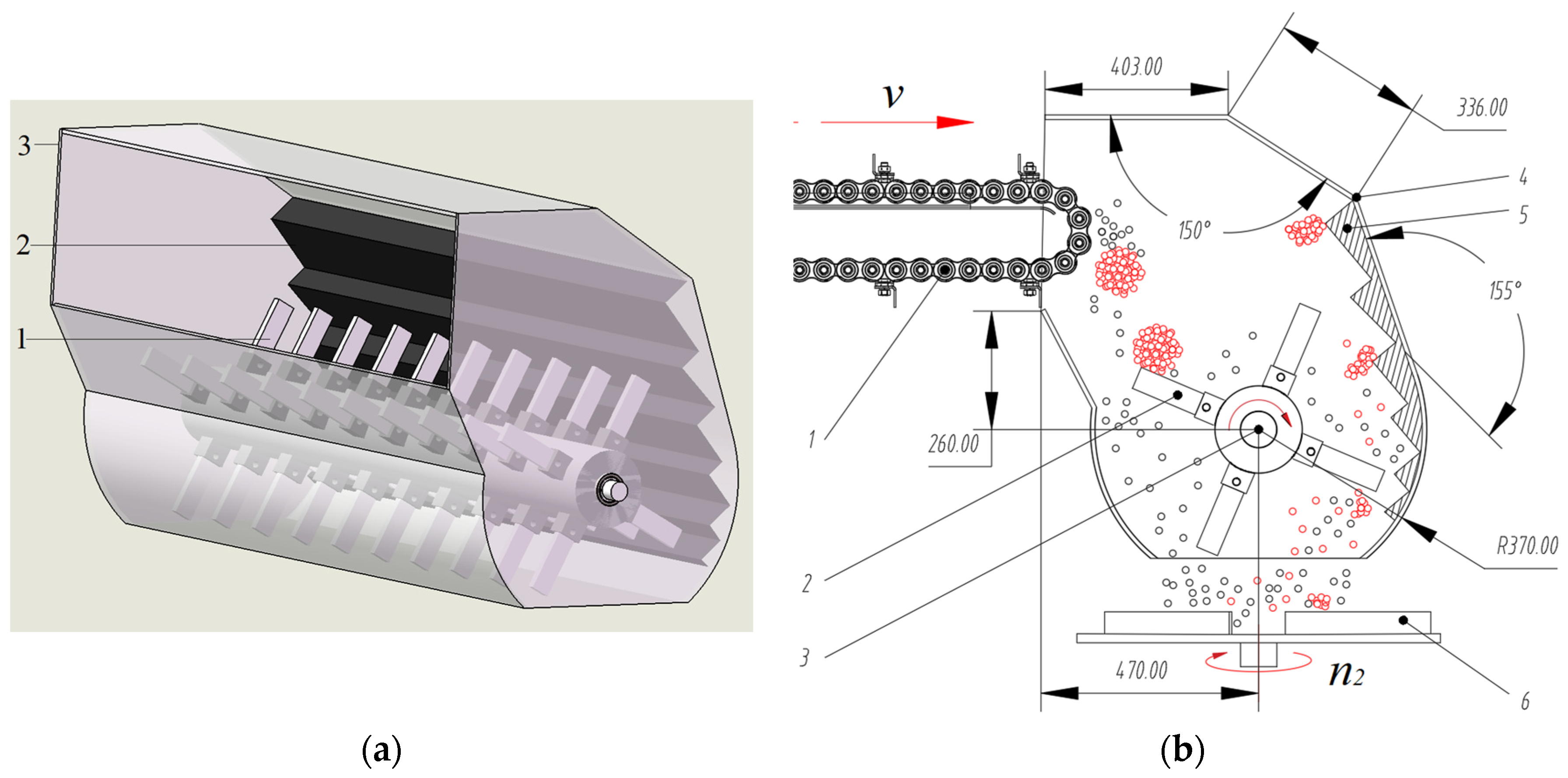
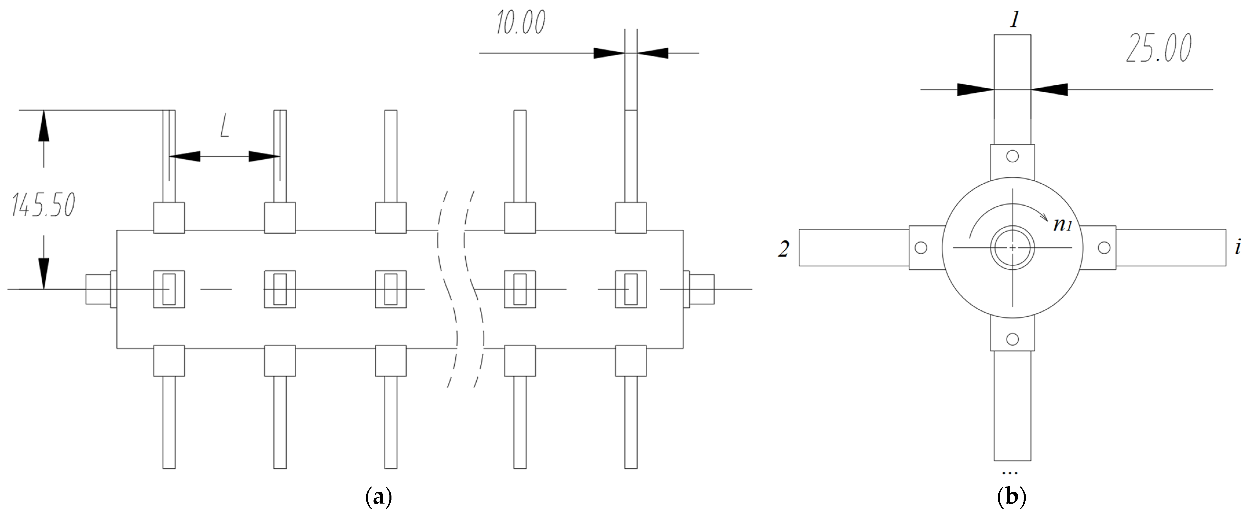
2.1.2. Structure and Working Principle of the Combined Rotor–Lining Plate Crushing Device

The rotor and lining plate crushing device mainly comprises a rotor, a lining plate, and an external wall. The rotor consists of a crushing shaft and the hammers fixed to the crushing shaft. The hammer is rectangular in shape, and the lining plate is zigzag in its cross-section and fixed on the inner side of the external wall, as shown in Figure 3a,b. The hammer and the lining plate are working parts in direct contact with the organic fertilizer, and both of them use surface-treated 45 # carbon steel as the material to ensure good wear resistance [33]. During operation, the hammer rotates at a high speed under the effect of the crushing shaft driven by the hydraulic motor. Under the effect of the conveying device, organic fertilizer is moved into the crushing device, where the caked fertilizer is crushed due to repeated impact from the high-speed rotating hammer and the collision, squeezing, and rubbing actions of the lining plate. Caked fertilizer that fails to be crushed completely is spread from the outlet of the crushing device due to the impact of the hammer and then crushed by the collision with the high-speed rotating disc.
The rotor is one of the key components in the crushing device. Figure 4 shows its structure and main parameters. The rotor speed and the layout of n1 hammers on the crushing shaft directly affect the crushing results, where the layout of the hammers on the crushing shaft is mainly determined by the number of circumferentially arranged hammer groups i (hereinafter referred to as the number of circumferential groups) on the crushing shaft and the axial installation distance L (hereinafter referred to as the axial distance). In order to obtain the optimal structure and working parameters, a Box–Behnken response surface optimization test was conducted based on the DEM.

2.2. Construction of Discrete Element Model

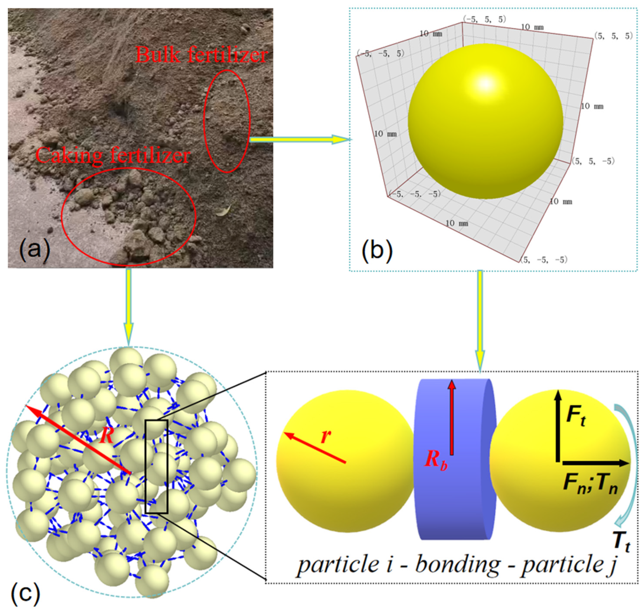
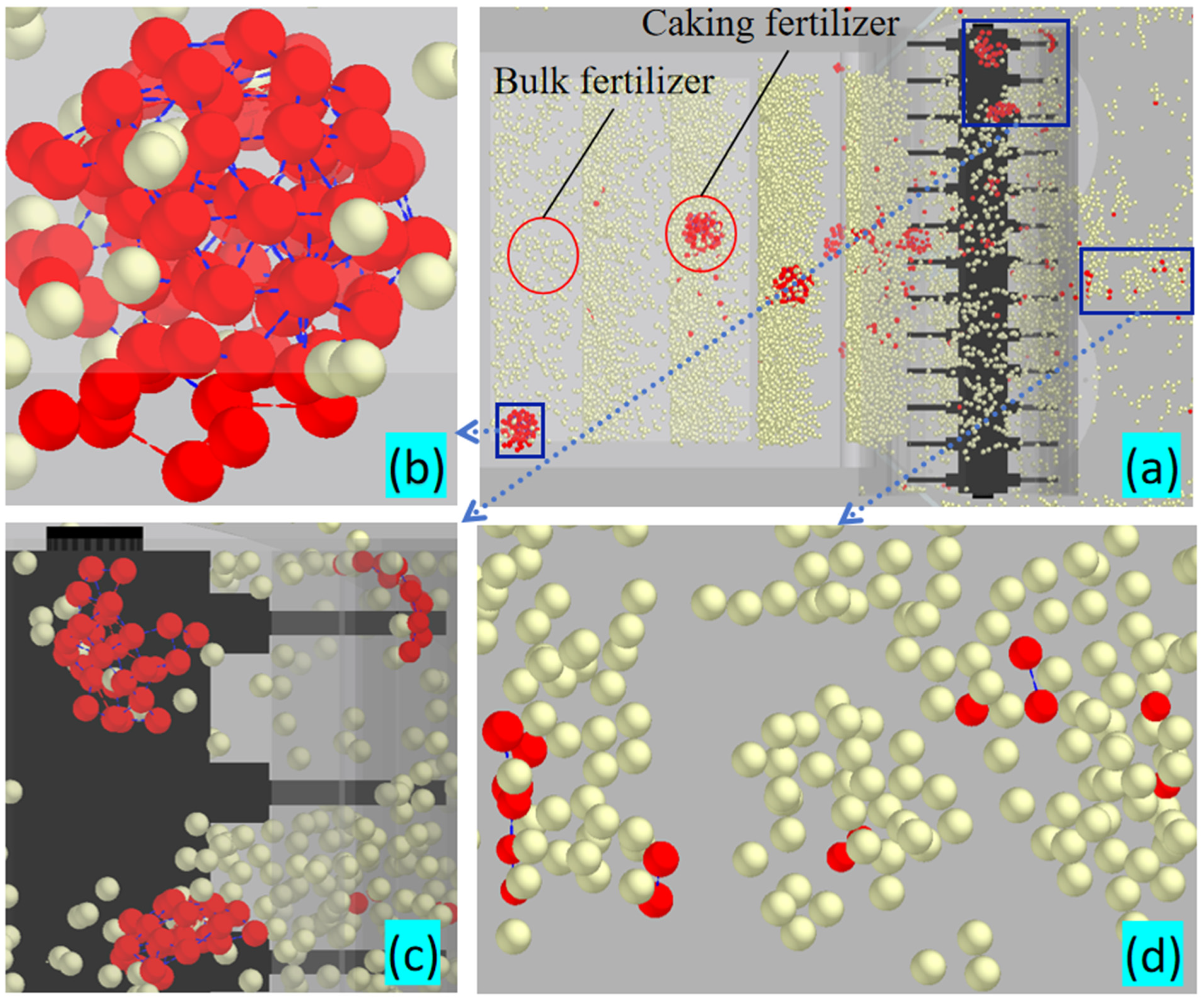
2.2.1. Construction of Discrete Element Model for Organic Fertilizer Particle Swarm

In practical applications, a proper contact model must be selected according to the properties of the simulated material.
The spreader designed in this study is mainly used for the spreading of organic fertilizer with a certain moisture content and a certain degree of caking. In other words, the organic fertilizer is mixed, consisting of bulk and caked fertilizer, as shown in Figure 5a. In order to accurately represent the interactive relationship between the granular organic fertilizers, an organic fertilizer particle group model built based on the combination of the Hertz–Mindlin with bonding (HMB) and Hertz–Mindlin with JKR (JKR) models was used. Through the observation of organic fertilizer, it is evident that the shapes and sizes of organic fertilizer granules vary significantly. Therefore, it is impossible to create a particle group model in simulation experiments that perfectly mirrors the actual situation. We use the long axis diameter among the three axes as its characteristic size, distinguishing between bulk and caked organic fertilizers based on whether the long axis diameter exceeds 10 mm. From the piled organic fertilizer materials, a random sample of 5 kg of organic fertilizer was selected. Upon measurement and statistical analysis, the average long axis diameter of the caked organic fertilizer in the sample was found to be 80 mm. In order to reduce the computational complexity of the numerical simulation and simplify the modelling process, the bulk organic fertilizer was modelled by a single spheric particle with a radius (r) of 5 mm, as shown in Figure 5b. The modelling of the caked organic fertilizer was based on the HMB contact model, where a number of single spherical granules served as the basic particles, which aggregated into a spherical particle cluster with a radius (R) of 40 mm through bonding, as shown in Figure 5c. Every spherical particle cluster consisted of 76 basic particles and 263 bonds, which could withstand a certain force/torque to prevent the relative movement between the granules in the tangential and normal directions.
After the bonding of the basic particles, the force(Fn, Ft)/torque(Tn, Tt) on the granules was 0 at the beginning, but it gradually increased in every timestep according to Formula (1) [34]:
{ δ F n = v n S n A δ t δ F t = v t S t A δ t δ T n = ω n S t J δ t δ T t = 1 2 ω t S n J δ t ,
where A denotes the contact area and J represents the rotational inertia. The calculation formula is as follows:
{ A = π R b 2 J = 1 2 π R b 4 ,
where Rb is the bonding radius (mm); Sn, t is the normal and tangential stiffnesses; δt is the timestep (s); vn, t is the normal and tangential velocities (m/s); ωn, t is the normal and tangential angular velocities (rad/s); Fn, t is the normal and tangential force of the particles (N); and Tn, t is the normal and tangential moment of the particles (N·m).
The caked organic fertilizer model is a breakable aggregate. That is to say, the bonding between the basic particles is of a finite scale, with the maximum applied normal and tangential stress having been indicated by Formula (3) [34]. When the value of normal and tangential stress exceeds the preset value, the bonding effect between the granules is lost, and breakage of the caked organic fertilizer occurs.
{ σ max < F n A + 2 T t J R b τ max < F t A + T n J R b ,
By referring to the relevant literature [18,35], the caked organic fertilizer can be set according to the bonding parameters provided in Table 1.
Due to the effect of moisture on granular organic fertilizer, adhesive contact occurs between the granules. In the classical Hertz contact model, only the elastic deformation is taken into account, without considering the bonding force between the contact surfaces of the granules. Hence, it is very difficult to accurately simulate the mechanical behaviours of the granular organic fertilizer. As a contact model with cohesive force, JKR considers the influence of the surface energy from the contact interface between the wet granules, using the motion law of particles based on the Hertz theory [36]. By allowing the modelling of a viscous system, this model can be used to simulate materials whose granules have been apparently bonded or aggregated together due to the electrostatic force or moisture content. In this model, the JKR surface energy has been used to represent the cohesive force between the particles [37]. In our research, the JKR model was used for the modelling of the cohesive force between the particles within the organic fertilizer particle group. The JKR surface energy was set to 0.075 J/m2 [38] for the construction of the particle group model, consisting of bulk and caked organic fertilizer granules, as shown in Figure 6.

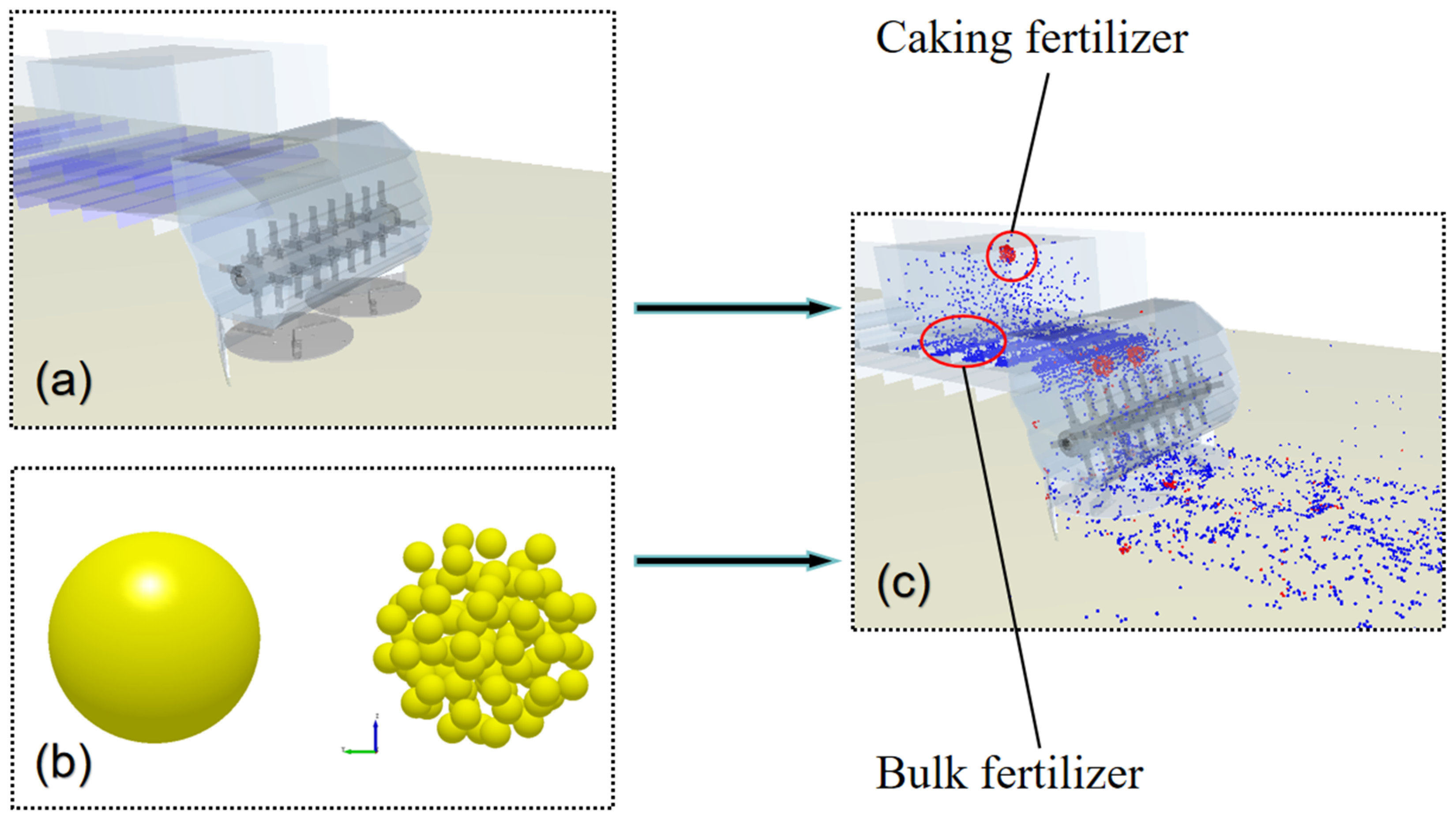
2.2.2. Construction of Discrete Element Model for Organic Fertilizer Crushing and Spreading

First, based on 3D modelling software (SOLIDWORKS 2018), a conveying–crushing–spreading model was built for the spreader, which was saved in STEP format (STEP is a standard for describing product data which include physical and functional aspects) and exported to the EDEM 2023 software, as shown in Figure 7a. Figure 7b shows the organic granular fertilizer model built according to the above method provided in Section 2.2.1. Then, the intrinsic parameters of the materials, including the organic fertilizer, the surface soil, and the operating components of the spreader in direct contact with the fertilizer, were set up. These intrinsic parameters and the corresponding contact parameters are provided in Table 2.
A particle plant was established in the fertilizer box, where bulk granules were generated in 10~32 s, at a rate of 2000 particles per second, and the blocky particles were generated in 10~30 s, with a total of 40 blocky particles being generated. The particle diameter was randomly distributed within 0.8~1.2 R. Every particle was generated at a random initial position, a random start angle, and in a random direction in the particle plant. According to the requirements of the standard GB/T 25401-2010 (Agricultural machinery—Manure spreaders—Environmental protection—Requirements and test methods) [41], the scraper speed of the conveying device was set to 0.05 m/s, and the operating velocity of the spreader was 0. 5 m/s. For the disc and the crushing device, the rotor speed was set to different levels according to the experimental requirement. The total simulation time was set to 32 s, and the data were stored every 0.04 s for the building of a crushing–spreading model, as shown in Figure 7c.

2.3. Simulation Test

2.3.1. Verification Test of Crushing Mechanism

Based on the established organic fertilizer-crushing-and-spreading model, a simulation test was conducted with the following parameter combination: a rotor speed of 540 r/min, an axial distance of 90 mm, and 4 circumferential groups. After the experiment, the organic fertilizer-crushing process was analyzed by simultaneously observing the distribution patterns of the caked organic fertilizer in the conveying device, in the crushing device, and on the ground after spreading. After the velocity vector diagram of particle movement in the crushing device at different moments was exported, the crushing mechanism of the crushing device could be clarified through the observation of the bond distribution pattern and the analysis of the trends in particle movement.

2.3.2. Box–Behnken Test

In our experiment, the broken bond rate and the coefficient of variation of spreading uniformity were taken as the indexes to test the combined rotor and lining plate crushing organic fertilizer spreader. As one of the indexes to evaluate the crushing effect of the spreader, the broken bond rate was calculated according to Formula (4):
W = M 1 M × 100 % ,
where W is the broken bond rate (%); M1 is the number of broken bonds; and M is the total number of bonds generated.
As an important index used to evaluate the spreading uniformity of the spreader, the coefficient of variation was determined through the following method according to the standard GB/T 25401-2010 [41]: In the EDEM-based analyst module, a square fertilizer collection grid with a side length of 500 mm was set up on the ground in the direction that the spreader moved, covering the entire spreading width. Additionally, the boundary line between two grid cells in the middle coincided exactly with the centre line of the spreader’s route. After operation, the mass of fertilizer in each collection grid cell was calculated according to Formulas (5)–(7):
C V = S X ¯ × 100 % ,
X ¯ = 1 n i = 1 n X i ,
S = 1 n 1 i = 1 n ( X i X ¯ ) 2 ,
where CV is the coefficient of variation (%); S is the standard deviation; X ¯ is the mean application amount for lateral fertilization (kg); Xi is the mass of fertilizer collected in the ith grid cell (kg); and n is the number of grid cells.
According to the implementability of the structural design and the trial test, the rotor speed, the axial distance, and the number of circumferential groups were taken as the influencing factors in the three-factor and three-level Box–Behnken response surface test, with the value of each factor being provided in Table 3.

3. Results and Discussion

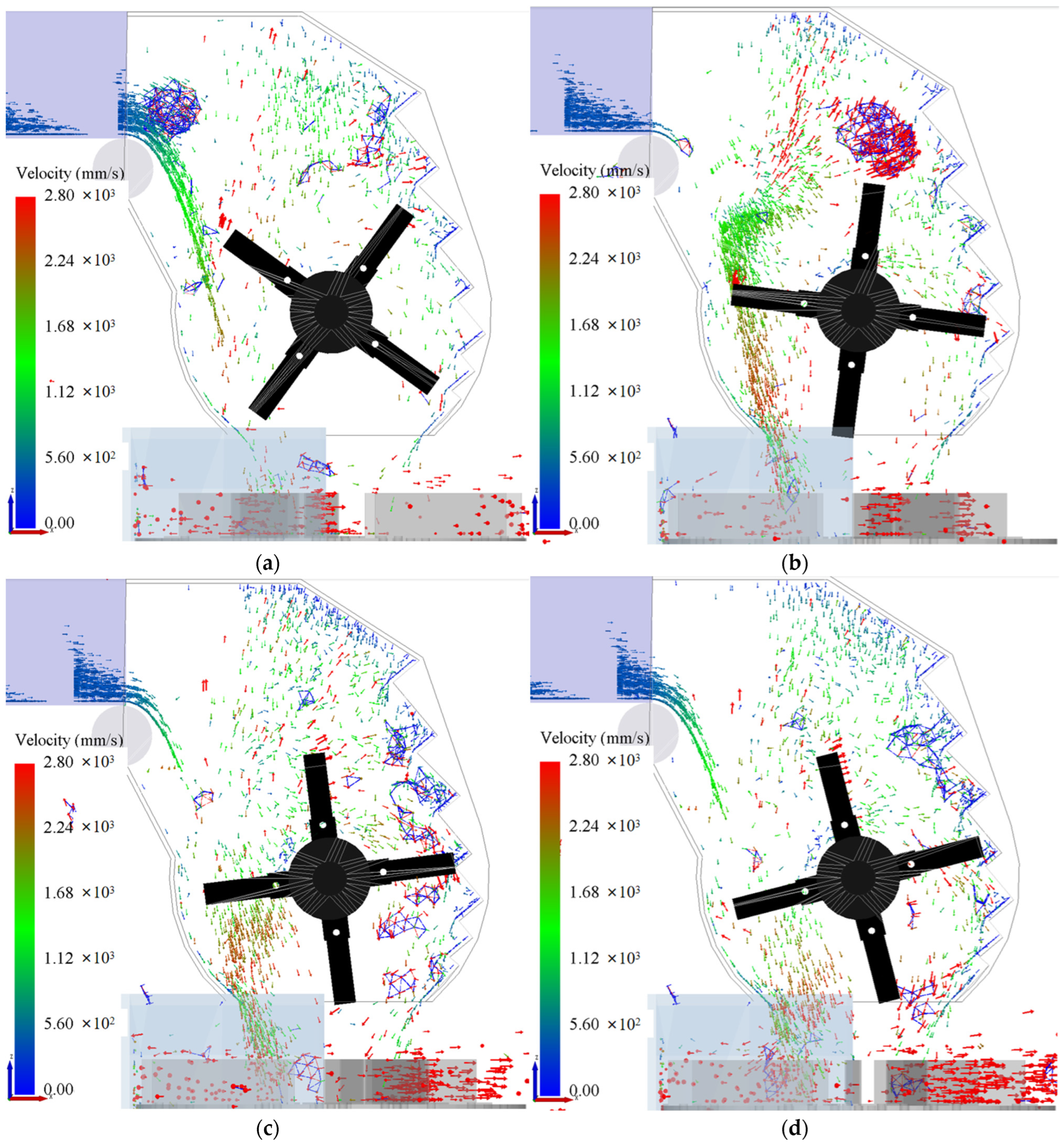
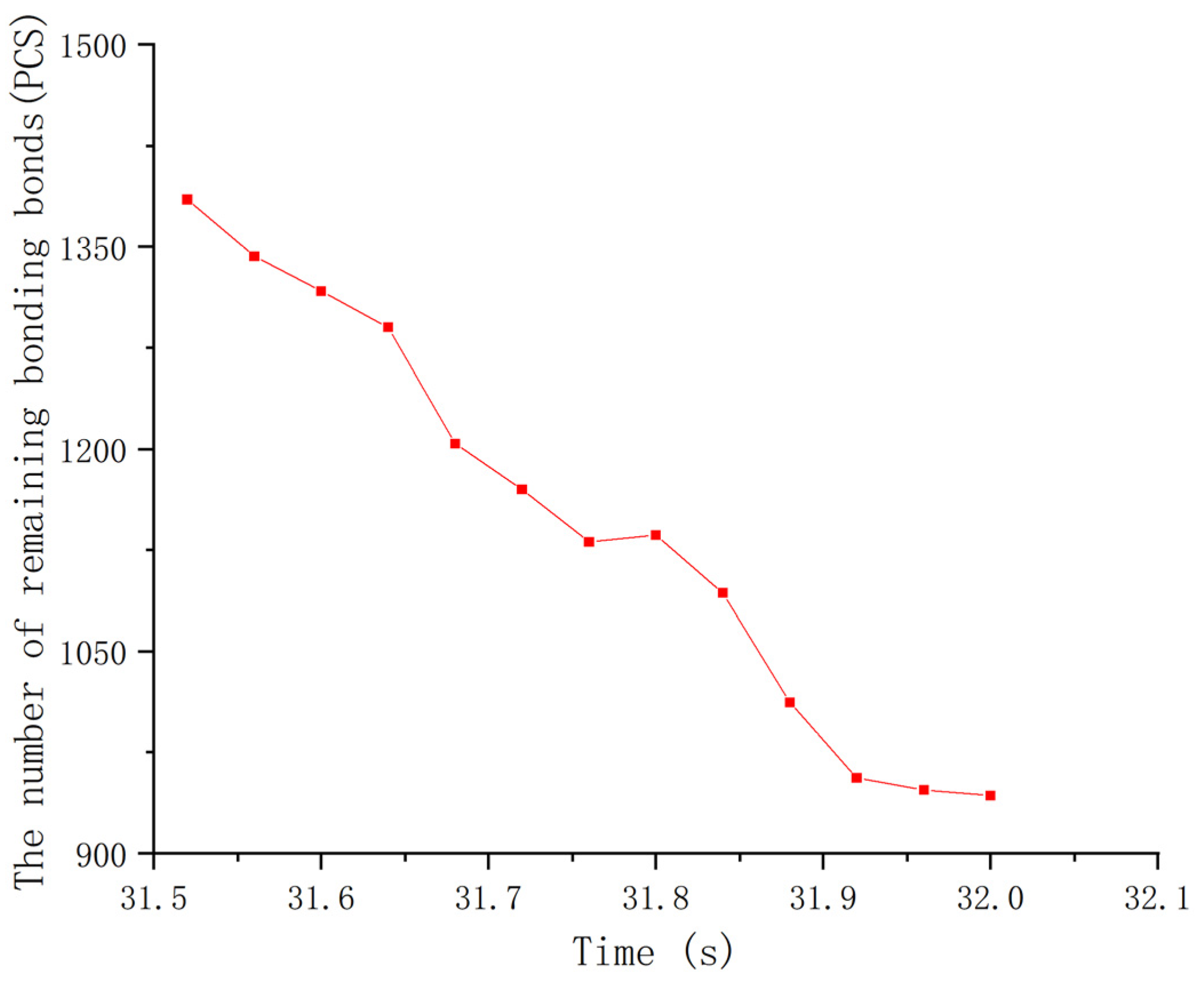
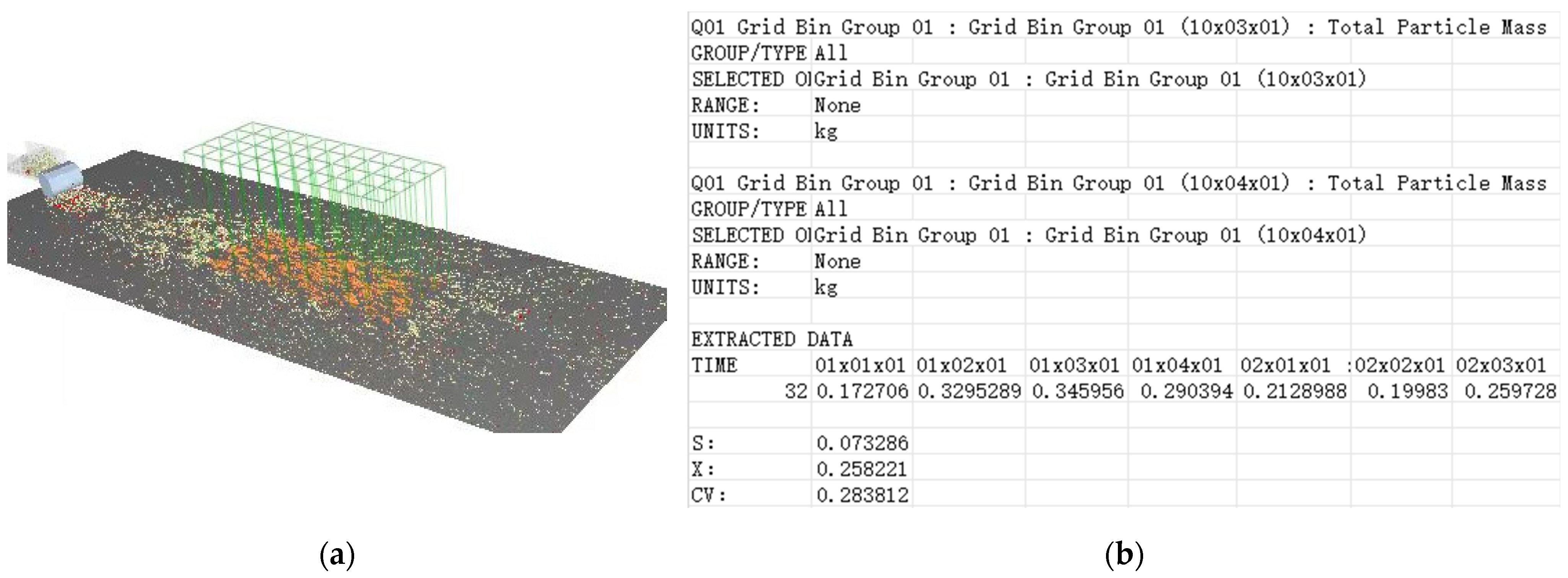
3.1. Verification Test Results of Crushing Mechanism

Figure 8 shows the morphological change in the particle cluster of caked organic fertilizer located at different positions but exported at the same time after the experiment.
As shown in Figure 8b,c, the caked organic fertilizer appeared as relatively complete clusters of spherical particles in the conveying device, but it showed up as particle clusters with irregular shapes and a medium particle size in the crushing device. As indicated by Figure 8a–d, when the spherical particle clusters were crushed in the crushing device and spread onto the ground by the spreading device, most of the bonds were broken, and they were shattered into smaller particle clusters or basic granules.
Figure 9 shows the velocity vector diagram of the particle movement at different moments, where the direction of the arrow, the colour, and the length separately represent the direction of movement, velocity, and kinetic energy of the particle.
As shown in Figure 9a,b, after the organic fertilizer was conveyed to the inlet of the crushing device via the conveying device, the bulk granules would drop to the spinning disc through the gap between the hammers or between the hammer and the external wall. Then, under the centrifugal effect of the disc, they would be spread onto the field. However, if the caked organic fertilizers failed to pass through the gap, they would be accelerated to collide with the external wall or the lining plate due to the impact of the hammer. As shown in Figure 9c,d, the medium-sized clusters of particles formed under the collision effect were squeezed and rubbed by the hammer and the lining plate in the falling process, and the bonds were further broken up, resulting in the formation of clusters with a smaller particle size. Some bonds would break in the process of the particle clusters dropping at a high speed from the outlet of the crushing device, colliding with the disc.

3.2. Box–Behnken Test Results and Analysis

3.2.1. The Influence of Various Factors on the Broken Bond Rate

Design-Expert is a commercial software to analyze statistical experimental designs. Design-Expert 13 was used for the Box–Behnken experimental design, where A, B, and C separately represented the rotor speed, the axial distance, and the number of circumferential groups. Each experiment was repeated three times to separately calculate the broken bond rate and the mean coefficient of variation of spreading uniformity. Taking the 3rd repetition of the 12th experiment as an example, when the EDEM post-processing module counted 32 s, the number of remaining bonding bonds in the domain was 943, and, as shown in Figure 10, from Formula (4), the broken bond rate was 91.04%.
W = M 1 M × 100 % = 263 × 40 943 263 × 40 × 100 % = 91.04 %
Taking the 3rd repetition of the 12th experiment as an example, according to the method described in 2.3.2, the grid bin group (10 × 4) was established in the EDEM 2023 post-processing module, and the mass of organic fertilizer particles in each grid was output to Excel 2019, which was calculated by Formulas (5)–(7), and the coefficient of variation was 28.38%, as shown in Figure 11.
The experimental scheme and results are provided in Table 4.
Analyses of variance (ANOVA) were performed separately on the broken bond rate and the coefficient of variation, according to the experimental data obtained based on Design-Expert 13, with the results provided in Table 5 and Table 6.
As shown in Table 5 and Table 6, the p value of each regression model was lower than 0.01, indicating the great significance of the models. The lack of fit of each model was 0.6380 and 0.6752, respectively, which was far greater than 0.05, indicating the non-significance of the models in terms of a lack of fit. It also meant that some unknown factors had very little effect on the experiment, revealing the high degree of fitness between these two models. The p values of both models revealed that, for the broken bond rate regression model, A, B, AB, and B2 reached extremely significant levels (p < 0.01), while AC and C2 reached significant levels (0.01 < p < 0.05). Other regression terms were not significant. For the coefficient of variation regression model, A, B, AC, and C2 reached extremely significant levels (p < 0.01), while BC and A2 reached significant levels (0.01 < p < 0.05), and other regression terms were not significant. The correlation coefficient R2 of each model was 0.9753 and 0.9639, respectively. Through the correction, the adjusted R2 values were 0.9437 and 0.9174, respectively. Both the correlation coefficient and the adjusted coefficient were very close to 1. The above data reveal that both models had rather good fitting and predictability, making them applicable to the optimization of the structural and operating parameters of the organic fertilizer spreader.
Multiple regression was fitted to the experimental data in Table 4 using the Design-Expert 13 software. After excluding insignificant items, the quadratic regression model for the coded values of the broken bond rate (Y1) and the coefficient of variation (Y2) could be obtained, as indicated by Formulas (8) and (9).
Y1 = 90.36 + 1.14 × A − 2.91 × B − 0.115 × C − 1.77 × AB − 0.81 × AC − 1.98 × B2 + 0.94 × C2,
Y2 = 27.51 + 3.46 × A − 1.98 × B − 0.345 × C + 1.88 × AC − 1.75 × BC + 1.56 × A2 − 2.12 × C2,

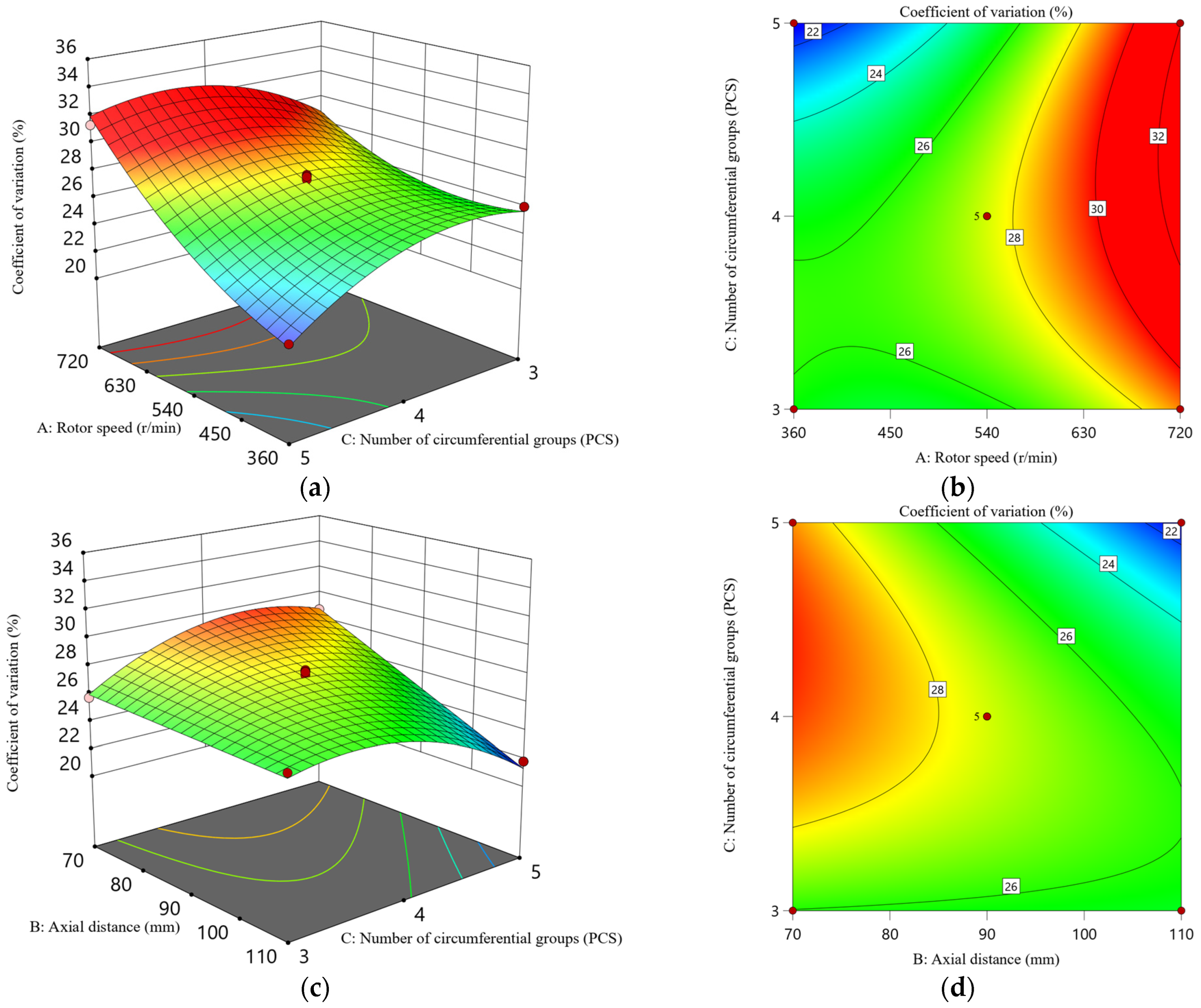
3.2.2. Response Surface Analysis

A response surface diagram and a contour map were developed based on the regression equation and by observing the change rule of the response surface morphology and the contour line. Using these, the influence of each factor on the broken bond rate (Y1) and the coefficient of variation (Y2) was analyzed, with the results being shown in Figure 12 and Figure 13.
Figure 12a,b show the interaction of the rotor speed and axial distance with the broken bond rate. According to the surface morphology, the broken bond rate was significantly affected by the interaction effect, and it reached the maximum and minimum values at the maximum velocity of rotation, revealing that, at a high rotor speed, the axial distance significantly affected the broken bond rate. At this point, the broken bond rate showed a trend of unidirectional reduction, with an increase in the axial distance. The broken bond rate was higher than 92% when the axial distance was small. However, it was reduced significantly with the increase in the axial distance. When the axial distance was 110 mm, the broken bond rate was as low as 86%. As shown in Figure 12b, when the axial distance was in the range of 100–110 mm, the broken bond rate varied very little and always stayed within the scope of 86–88% in the whole velocity range. The smaller the axial distance, the more contour lines for different broken bond rates appeared, showing that the variation in the broken bond rate gradually became obvious.
As shown in Figure 12c,d, the interactive surface between the rotor speed, the number of groups, and the broken bond rate was rather flat, revealing that the broken bond rate varied very little under the simultaneous effect of the rotor speed and the number of groups. According to the contour map, under this interactive effect, the broken bond rate only varied within 89–93%, with a maximum change of only around 4%.
As shown in Figure 13a,b, the surface of interaction between the rotor speed, the number of circumferential groups, and the coefficient of variation revealed that the increase in rotor speed resulted in a large coefficient of variation. When the rotor speed was at its minimum level, the coefficient of variation was less than 28%, which could be reduced to 22% when the number of circumferential groups was five. This revealed that, under the interactive effect of the rotor speed and the number of circumferential groups, the rotor speed served as an experimental factor playing a critical role in determining the value of the coefficient of variation. From the perspective of monotonicity, the coefficient of variation rose and then declined with the increase in the number of circumferential groups, but it showed a monotone increase with the rise in rotor speed.
As shown in Figure 13c,d, the surface of interaction between the axial distance, the number of circumferential groups, and the coefficient of variation revealed that the smaller the axial distance, the higher the overall value range of the coefficient of variation. However, this value became smaller with an increase in the axial distance, indicating that the coefficient of variation was very susceptible to the axial distance, and it always showed a trend of monotonically decreasing with the increase in axial distance. However, under the effect of axial distance and the number of circumferential groups, the coefficient of variation changed from a trend of monotonically increasing to a pattern of increasing first and then decreasing. When the axial distance increased to 110 mm and a total of five groups were available, the coefficient of variation was reduced to less than 22%.

3.3. Optimal Parameter Design and Verification

In order to obtain the optimal structure and operating parameters of the crushing device in the spreader, the maximum broken bond rate and the minimum coefficient of variation were considered as the optimization objectives. Then, a mathematical model for optimization was established under the constraint conditions determined based on the real conditions, according to Formula (10):
{ m a x Y 1 = f 1 ( A , B , C ) ; m i n Y 2 = f 2 ( A , B , C ) s . t . { 360 A 720 70 B 110 3 C 5 ,
Based on the optimization module in Design-Expert, the optimal solutions of the mathematical model were found with the optimal parameter combination, provided as follows: a rotor speed of 388.55 r/min, an axial distance of 90.27 mm, and five circumferential groups. With these parameters, the predicted values of the model were as follows: a broken bond rate of 90.86% and a coefficient of variation of 21.45%. To facilitate model selection for power, processing, and manufacturing, the following experimental parameter combination was determined and verified: a rotor speed of 388 r/min (6.47 Hz), an axial distance of 90.30 mm, and five circumferential groups. Based on this, three parallel tests were performed to obtain an average broken bond rate of 90.03% and a mean coefficient of variation of 22.12%. The verification showed that the relative errors between the experimental results and the predicted values of the model were 0.91 and 3.12%, respectively, proving that the model had a high accuracy.

4. Conclusions

Based on the experimental factors of the rotor speed, axial distance, and number of circumferential groups, a three-factor and three-level Box–Behnken response surface optimization test was performed, where the broken bond rate of caked organic fertilizer and the coefficient of variation were taken as the experimental indexes. Additionally, regression models between the experimental factors and the broken bond rate and coefficient of variation were established. By optimizing the regression models, the optimal parameter combination was finally obtained, which included a rotor speed of 388 r/min (6.47 Hz), an axial distance of 90.30 mm, and five circumferential groups. Based on this optimal parameter combination, the mean broken bond rate was 90.03%, and the mean coefficient of variation was 22.12%. After verification, the relative errors between the experimental results and the predicted values of the model were 0.91% and 3.12%, respectively, proving the high forecast accuracy of the model. Our research will provide a basis for the trial production of organizer fertilizer spreader prototypes and the optimization of their working parameters.
The composition and moisture content of organic fertilizer can affect the bonding strength between particles; however, it is currently unclear how these factors influence the efficiency of spreaders. Future experimental studies will be conducted on the prototype machine hereby presented to learn the impact of these factors on the operational efficiency of spreaders.

Author Contributions

Conceptualization, B.X.; data curation, L.G.; formal analysis, Q.C.; funding acquisition, Q.C.; investigation, B.X.; methodology, B.X.; project administration, Q.C.; resources, Q.C.; software, B.X.; supervision, Q.C.; visualization, L.G.; writing—original draft, B.X.; and writing—review and editing, B.X. and L.H. All authors have read and agreed to the published version of the manuscript.

Funding

This research was funded by the Key R&D Programme of the Shanxi Province, China, with grant number [201903D211002-04].

Data Availability Statement

Data are contained within this article. The data presented in this study can be requested from the authors.

Conflicts of Interest

The authors declare no conflicts of interest.

References

  1. Burke, W.J.; Jayne, T.S.; Snapp, S.S. Nitrogen efficiency by soil quality and management regimes on Malawi farms: Can fertilizer use remain profitable? World Dev. 2022, 152, 105792. [Google Scholar] [CrossRef]
  2. Bai, Y.C.; Chang, Y.Y.; Hussain, M.; Lu, B.; Zhang, J.P.; Song, X.B.; Lei, X.S.; Pei, D. Soil chemical and microbiological properties are changed by long-term chemical fertilizers that limit ecosystem functioning. Microorganisms 2020, 8, 694. [Google Scholar] [CrossRef] [PubMed]
  3. Ning, C.C.; Wang, J.W.; Cai, K.Z. The effects of organic fertilizers on soil fertility and soil environmental quality: A review. Ecol. Environ. Sci. 2016, 25, 175–181, (In Chinese with English Abstract). [Google Scholar] [CrossRef]
  4. Wang, H.X.; Xu, J.L.; Liu, X.J.; Zhang, D.; Li, L.W.; Li, W.; Sheng, L.X. Effects of long-term application of organic fertilizer on improving organic matter content and retarding acidity in red soil from China. Soil Tillage Res. 2019, 195, 104382. [Google Scholar] [CrossRef]
  5. Zhang, K.Q.; Du, L.Z.; Du, H.Y.; Shen, S.Z. Application of livestock and poultry waste to agricultural land: A review. J. Agro Environ. Sci. 2021, 40, 2472–2481, (In Chinese with English Abstract). [Google Scholar] [CrossRef]
  6. Wan, L.J.; Tian, Y.; He, M.; Zheng, Y.Q.; Lyu, Q.; Xie, R.J.; Ma, Y.Y.; Deng, L.; Yi, S.L. Effects of Chemical Fertilizer Combined with Organic Fertilizer Application on Soil Properties, Citrus Growth Physiology, and Yield. Agriculture 2021, 11, 1207. [Google Scholar] [CrossRef]
  7. Dong, R.X.; Abdelkerim-Ouba, D.; Liu, D.Y.; Ma, X.F.; Wang, S. Impacts of Partial Substitution of Chemical Fertilizer with Organic Manure on the Kinetic and Thermodynamic Characteristics of Soil β-Glucosidase. Agronomy 2023, 13, 1065. [Google Scholar] [CrossRef]
  8. Xie, J.Y.; Zhang, H.F.; Luo, Y.Q.; Meng, H.S.; Zhang, J.; Hong, J.P.; Xu, M.G. Driving factors of improving fertility and maize yields in the reclaimed soils by seven years of applied organic manure and chemical fertilizer. Trans. Chin. Soc. Agric. Eng. 2024, 40, 142–152, (In Chinese with English Abstract). [Google Scholar] [CrossRef]
  9. Du, W.Y.; Tang, S.; Wang, H. The status of organic fertilizer industry and organic fertilizer resources in China. Soil Fertil. Sci. China 2020, 3, 210–219, (In Chinese with English Abstract). [Google Scholar] [CrossRef]
  10. Wu, J.; Geng, Y.; Zhou, Y.J.; Lin, C.Y.; Deng, J.; Wang, P. Research Situation and Development Ideas of Organic Fertilizer Applicator. Agric. Eng. 2022, 12, 19–22, (In Chinese with English Abstract). [Google Scholar] [CrossRef]
  11. Sun, D.X.; Li, M.J.; Wu, A.B.; Liang, Q.; Zhang, A. Research progress of organic fertilizer and its supporting mechanization technology. J. Chin. Agric. Mech. 2019, 40, 72–80, (In Chinese with English Abstract). [Google Scholar] [CrossRef]
  12. Zeng, Z.W.; Ma, X.; Cao, X.L.; Li, Z.H.; Wang, X.C. Critical review of applications of discrete element method in agricultural engineering. Trans. Chin. Soc. Agric. Mach. 2021, 52, 1–20, (In Chinese with English Abstract). [Google Scholar] [CrossRef]
  13. Yuan, Q.C.; Xu, L.M.; Xing, J.J.; Duan, Z.Z.; Ma, S.; Yu, C.C.; Chen, C. Parameter calibration of discrete element model of organic fertilizer particles for mechanical fertilization. Trans. Chin. Soc. Agric. Eng. 2018, 34, 21–27, (In Chinese with English Abstract). [Google Scholar] [CrossRef]
  14. Peng, C.W.; Xu, D.J.; He, X.; Tang, Y.H.; Sun, S.L. Parameter calibration of discrete element simulation model for pig manure organic fertilizer treated with Hermetia illucen. Trans. Chin. Soc. Agric. Eng. 2020, 36, 212–218, (In Chinese with English Abstract). [Google Scholar] [CrossRef]
  15. Chen, G.B.; Wang, Q.J.; Li, W.Y.; He, J.; Li, H.W.; Yu, C.C. Design and experiment of double roller differential speed crushing fertilizer device for block organic fertilizer. Trans. Chin. Soc. Agric. Mach. 2021, 52, 65–76, (In Chinese with English Abstract). [Google Scholar] [CrossRef]
  16. Chen, G.B.; Wang, Q.J.; Li, H.W.; He, J.; Lu, C.Y.; Xu, D.J.; Sun, M.Y. Experimental research on a propeller blade fertilizer transport device based on a discrete element fertilizer block model. Comput. Electron. Agric. 2023, 208, 107781. [Google Scholar] [CrossRef]
  17. Chen, G.B.; Wang, Q.J.; Wen, L.H.; He, J.; Lu, C.Y.; Zhang, X.Y. Design and experiment of solid organic fertilizer crushing and striping machines. Trans. Chin. Soc. Agric. Eng. 2023, 39, 13–24, (In Chinese with English Abstract). [Google Scholar] [CrossRef]
  18. Xu, B.; Cui, Q.L.; Zheng, D.C. Improvement design and simulation analysis on centrifugal disc organic fertilizer spreader. INMATEH Agric. Eng. 2023, 70, 328–336. [Google Scholar] [CrossRef]
  19. Hwang, S.J.; Nam, J.S. DEM simulation model to optimise shutter hole position of a centrifugal fertiliser distributor for precise application. Biosyst. Eng. 2021, 204, 326–345. [Google Scholar] [CrossRef]
  20. Fan, C.S.; He, R.Y.; Shi, Y.Y.; He, L.N. Structure and operation mode of centrifugal side-throwing organic fertilizer spreader for greenhouses. Powder Technol. 2024, 438, 119457. [Google Scholar] [CrossRef]
  21. Zinkevičienė, R.; Jotautienė, E.; Juostas, A.; Comparetti, A.; Vaiciukevičius, E. Simulation of granular organic fertilizer application by centrifugal spreader. Agronomy 2021, 11, 247. [Google Scholar] [CrossRef]
  22. Balsari, P.; Dinuccio, E.; Gioelli, F.; Airoldi, G. Band spreader for the application of slurry solid fractions to orchards. Biosyst. Eng. 2015, 136, 69–76. [Google Scholar] [CrossRef]
  23. Hu, J.; He, J.C.; Wang, Y.; Wu, Y.P.; Chen, C.; Ren, Z.Y.; Li, X.X.; Shi, S.J.; Du, Y.P.; He, P.X. Design and study on lightweight organic fertilizer distributor. Comput. Electron. Agric. 2020, 169, 105149. [Google Scholar] [CrossRef]
  24. Liu, H.X.; Zhao, Y.J.; Xie, Y.T.; Zhang, Y.M.; Shang, J.J. Design and Experiment of Spiral Blades Auxiliary Roller of Organic Fertilizer Side Throwing Device. Trans. Chin. Soc. Agric. Mach. 2023, 54, 107–119, (In Chinese with English Abstract). [Google Scholar] [CrossRef]
  25. Hao, Y.J.; Wang, C.; Wu, A.B.; Liu, K.K.; Fan, P.; Sun, D.X. Design and test of precise organic fertilizer applicator. J. Agric. Mech. Res. 2021, 43, 87–94, (In Chinese with English Abstract). [Google Scholar] [CrossRef]
  26. Li, S.B.; Li, Q.H.; Sun, D.X. Design and test of self-propelled fertilizer applicator. J. Chin. Agric. Mech. 2023, 44, 202–209, (In Chinese with English Abstract). [Google Scholar] [CrossRef]
  27. Smits, M.; Kronbergs, E. Determination centre of percussion for hammer mill hammers. In Proceedings of the International Conference Engineering for Rural Development, Jelgava, Latvia, 24–26 May 2017; pp. 364–368. [Google Scholar]
  28. Tanaś, W.; Szczepaniak, J.; Kromulski, J.; Szymanek, M.; Tanaś, J.; Sprawka, M. Modal analysis and acoustic noise characterization of a grain crusher. Ann. Agric. Environ. Med. 2018, 25, 433–436. [Google Scholar] [CrossRef] [PubMed]
  29. Li, C.D.; Liu, Y.; Cao, L.Y.; Bai, Y.Q.; Wang, F.; Zhang, S.W. Experimental research on optimization of working parameters of hammer mill. J. Chin. Agric. Mech. 2024, 45, 122–129, (In Chinese with English Abstract). [Google Scholar] [CrossRef]
  30. Hu, L.; Zhu, H.; Hua, J. DEM simulation of energy transitions in a hammer mill: Effect of impeller configurations, agitation speed, and fill level. Powder Technol. 2021, 394, 1077–1093. [Google Scholar] [CrossRef]
  31. Xu, J. Optimization Study on Hammer Size and Arrangement of SWFP66X60A Hammer Mill. Master’s Thesis, Jiangnan University, Wuxi, China, 2009. [Google Scholar]
  32. Cotabarren, I.; Fernández, M.P.; Battista, A.D.; Pia, J. Modeling of maize breakage in hammer mills of different scales through a population balance approach. Powder Technol. 2020, 375, 433–444. [Google Scholar] [CrossRef]
  33. Wang, S.; Chu, P.; Tang, B.; Tian, X.; Wang, X.; Lin, Q. Enhancement of surface properties of 45# carbon steel using plasma immersion ion implantation. Thin Solid Film. 1997, 311, 190–195. [Google Scholar]
  34. Wu, J.; Tang, Q.; Mu, S.L.; Jiang, L.; Hu, Z.C. Test and optimization of oilseed rape (Brassica napus L.) threshing device based on DEM. Agriculture 2022, 12, 1580. [Google Scholar] [CrossRef]
  35. Wu, N. Research and Design of 2F50 Manure Spreader. Master Thesis, Chinese Academy of Agricultural Mechanization Sciences, Beijing, China, 2016. (In Chinese with English Abstract). [Google Scholar]
  36. Wu, T.; Huang, W.F.; Chen, X.S.; Ma, X.; Han, Z.Q.; Pan, T. Calibration of discrete element model parameters for cohesive soil considering the cohesion between particles. J. South China Agric. Univ. 2017, 38, 93–98, (In Chinese with English Abstract). [Google Scholar] [CrossRef]
  37. Johnson, K.L.; Kendall, K.; Roberts, A.D. Surface Energy and the Contact of Elastic Solids. Proc. R. Soc. A Math. Phys. Eng. Sci. 1971, 324, 301–313. [Google Scholar] [CrossRef]
  38. Wang, L.M.; Fan, S.Y.; Cheng, H.S.; Meng, H.B.; Shen, Y.J.; Wang, J.; Zhou, H.B. Calibration of contact parameters for pig manure based on EDEM. Trans. Chin. Soc. Agric. Eng. 2020, 36, 95–102, (In Chinese with English Abstract). [Google Scholar] [CrossRef]
  39. Li, L.; Cui, Q.L.; Zhang, Y.Q.; Hou, H.M.; Xi, P.; Hao, C. Experimental study on scattering performance of organic fertilizer spreader based on EDEM. Agric. Eng. 2022, 12, 88–94, (In Chinese with English Abstract). [Google Scholar] [CrossRef]
  40. Liu, H.X.; Du, C.L.; Yin, L.W.; Zhang, G.F. Shooting flow shape and control of organic fertilizer side throwing on inclined opposite discs. Trans. Chin. Soc. Agric. Mach. 2022, 53, 168–177, (In Chinese with English Abstract). [Google Scholar] [CrossRef]
  41. GB/T 25401-2010; Agricultural Machinery—Manure Spreaders—Environmental Protection—Requirements and Test Methods. The Standardization Administration of China: Beijing, China, 2010. (In Chinese)
Figure 1. Operation site diagram of traditional disc spreader.
Agronomy 14 01732 g001
Figure 2. Three-dimensional model of a combined rotor and lining plate crushing organic fertilizer spreader. 1. Crawler travelling device; 2. conveying device; 3. fertilizer box; 4. dose-regulating plate; 5. rotor–lining plate combined crushing device; and 6. spreading device.
Agronomy 14 01732 g002
Figure 3. Structure and working principle diagram of the crushing device. (a) 3D model of the crushing device: 1. rotor; 2. lining plate; and 3. external wall. (b) Working principle and structural parameter diagram of the crushing device: 1. conveying device; 2. hammer; 3. crushing shaft; 4. external wall; 5. lining plate; and 6. spreading device.
Agronomy 14 01732 g003
Figure 4. Schematic diagram of the rotor structure and the main parameters. (a) Front view and (b) side view.
Agronomy 14 01732 g004
Figure 5. Process of constructing a discrete element model for organic fertilizers. (a) Physical image of organic fertilizer; (b) discrete element model of bulk organic fertilizer; and (c) discrete element model of caked organic fertilizer.
Agronomy 14 01732 g005
Figure 6. Organic fertilizer particle group model.
Agronomy 14 01732 g006
Figure 7. Construction process of an organic fertilizer-crushing–spreading model. (a) Three-dimensional model of an organic fertilizer-conveying–crushing–spreading device; (b) discrete element model of organic fertilizer particle; and (c) organic fertilizer-crushing–spreading model.
Agronomy 14 01732 g007
Figure 8. The morphological change in the particle cluster of caked organic fertilizer. (a) Top view of a simulated operation for the crushing and spreading of organic fertilizer; (b) morphology of the organic fertilizer particle clusters inside the conveying device; (c) morphology of the organic fertilizer particle clusters inside the crushing device; and (d) morphology of the organic fertilizer particle clusters spread on the ground.
Agronomy 14 01732 g008
Figure 9. The velocity vector diagram of particle movement at different moments. (a) 11.8 s; (b) 11.96 s; (c) 12.04 s; (d) 12.08 s.
Agronomy 14 01732 g009
Figure 10. Number of bonds at different times.
Agronomy 14 01732 g010
Figure 11. Coefficient of variation’s calculation process. (a) Grid bin group and (b) data output and calculation.
Agronomy 14 01732 g011
Figure 12. Response surface analysis of the interacting factors affecting the broken bond rate. (a) Response surface plot of the effect of the rotor speed and the axial distance on the broken bond rate. (b) Contour plot of the effect of the rotor speed and the axial distance on the broken bond rate. (c) Response surface plot of the effect of the rotor speed and the number of circumferential groups on the broken bond rate. (d) Contour plot of the effect of the rotor speed and the number of circumferential groups on the broken bond rate. The change in color from blue to red indicates that the broken bond rate changes from small to large.
Agronomy 14 01732 g012
Figure 13. Response surface analysis of the interacting factors affecting the coefficient of variation. (a) Response surface plot of the effect of the rotor speed and the number of circumferential groups on the coefficient of variation. (b) Contour plot of the effect of the rotor speed and the number of circumferential groups on the coefficient of variation. (c) Response surface plot of the effect of the axial distance and the number of circumferential groups on the coefficient of variation. (d) Contour plot of the effect of the axial distance and the number of circumferential groups on the coefficient of variation. The change in color from blue to red indicates that the coefficient of variation changes from small to large.
Agronomy 14 01732 g013
Table 1. Bonding parameters of HMB.
ParametersValues
Normal Stiffness per unit area1 × 108 N/m−3
Shear Stiffness per unit area5 × 107 N/m−3
Critical Normal Stress0.55 MPa
Critical Shear Stress0.55 MPa
Bonded Disc Radius5 mm
Table 2. Intrinsic material parameters and contact parameters [18,35,39,40].
ProjectParametersValues
Organic FertilizerPoisson’s ratio0.315
Shear modulus/Pa5.5 × 106
Density/(kg·m−3)1.25 × 103
SteelPoisson’s ratio0.30
Shear modulus/Pa7.90 × 1010
Density/(kg·m−3)7.90 × 103
SoilPoisson’s ratio0.30
Shear modulus/Pa5 × 107
Density/(kg·m−3)2.60 × 103
Organic Fertilizer–Organic FertilizerCoefficient of restitution0.01
Static friction coefficient1.2
Rolling friction coefficient1
Organic Fertilizer–SteelCoefficient of restitution0.6
Static friction coefficient0.75
Rolling friction coefficient0.75
Organic Fertilizer–SoilCoefficient of restitution0.4
Static friction coefficient0.66
Rolling friction coefficient0.18
Table 3. Code of experimental factors.
FactorsCode Level
−101
Rotor speed (r/min)360540720
Axial distance (mm)7090110
Number of circumferential groups345
Table 4. Box–Behnken experimental design and response values.
NumberFactorsThe Broken Bond Rate (%) Coefficient of
Variation (%)
Rotor Speed AAxial Distance BNumber of
Circumferential Groups C
1−11086.3321.94
201186.9321.81
30−1−192.9125.74
4−1−1088.2128.73
500090.1125.41
610191.2931.31
71−1093.8034.23
810−193.6328.40
900089.8527.95
10−10190.4221.45
1101−185.6425.84
1200091.0728.04
13−10−189.5226.05
1400091.2827.68
1511084.8531.93
160−1192.1428.70
1700089.8027.89
Table 5. ANOVA of the broken bond rate.
SourceSum of Squares dfMean SquareF-Valuep-ValueSignificance
Model114.05912.6730.77<0.0001**
A10.33110.3325.080.0016**
B67.92167.92164.93<0.0001**
C0.105810.10580.25690.6278
AB12.50112.5030.350.0009**
AC2.6212.626.370.0396*
BC1.0611.062.580.1525
A20.104110.10410.25280.6305
B216.30116.3039.570.0004**
C23.8013.809.230.0189*
Residual2.8870.4118
Lack of Fit0.915130.30500.62020.6380
Pure Error1.9740.4919
Cor Total116.9316
Note: ** means extremely significant (p < 0.01); and * means significant (0.01 < p < 0.05).
Table 6. ANOVA of the coefficient of variation.
SourceSum of Squares dfMean SquareF-Valuep-ValueSignificance
Model187.91920.8820.750.0003**
A95.91195.9195.30<0.0001**
B31.52131.5231.320.0008**
C0.952210.95220.94620.3631
AB5.0415.045.010.0603
AC14.10114.1014.010.0072**
BC12.22112.2212.140.0102*
A210.07110.0710.010.0158*
B20.299610.29960.29770.6023
C219.25119.2519.130.0033**
Residual7.0471.01
Lack of Fit2.0530.68470.54880.6752
Pure Error4.9941.25
Cor Total194.9516
Note: ** means extremely significant (p < 0.01); and * means significant (0.01 < p < 0.05).
Disclaimer/Publisher’s Note: The statements, opinions and data contained in all publications are solely those of the individual author(s) and contributor(s) and not of MDPI and/or the editor(s). MDPI and/or the editor(s) disclaim responsibility for any injury to people or property resulting from any ideas, methods, instructions or products referred to in the content.

