Article

Design and Experiment of an Inter-Row Weeding Machine Applied in Soybean and Corn Strip Compound Planting (SCSCP)

School of Mechanical Engineering, Yangzhou University, Yangzhou 225127, China
*
Author to whom correspondence should be addressed.
Agronomy 2024, 14(9), 2136; https://doi.org/10.3390/agronomy14092136
Submission received: 19 August 2024 / Revised: 13 September 2024 / Accepted: 17 September 2024 / Published: 19 September 2024
(This article belongs to the Section Precision and Digital Agriculture)

Abstract

:
To address the lack of specialized machinery for the mechanical weeding of SCSCP in the Huang Huai Hai region, this study designs a mechanized inter-row weeding machine for SCSCP. The machine features a reciprocating weeding shovel and an adaptive contouring mechanism for cultivation and soil loosening. This paper details the machine’s principles by analyzing the geometric relationship and mechanical model between the corresponding profiling quantities, which determine the relevant parameters for adaptive contouring to ensure stable operation on undulating ground. Furthermore, by optimizing the design of the weeding shovel’s reciprocating motion mechanism, combining EDEM simulation with the weeding shovel–soil interaction, it has been determined that, at various PTO shaft speeds, the optimal weeding efficacy is achieved with a blade-type weeding shovel structure when operating at a forward speed of 3.5 km/h. Field experiments were conducted with different PTO shaft speeds and weeding depths, using weeding and seedling injury rates as performance indicators. The results showed that, based on the optimal speed, the PTO shaft speed is 760 r/min, the operating depth is 3–5 cm, and the average row weeding rate is 90.4%. The average soybean and corn seedling injury rate is 3.4% and 4.2%, meeting the technical requirements for mechanical weeding.

1. Introduction

Food security is a vital component of national security. In recent years, the intensification of global changes, driven by regional conflicts and the COVID-19 pandemic, has made national food security more crucial at this stage than at any other time in history for any country [1]. Sustainable agricultural development is the most critical foundation and guarantee of national food security. Presently, China is a major agricultural nation but not a strong one [2]. Yang et al. [3] confirmed that agricultural mechanization can significantly increase agricultural productivity in the context of fragmented farmland and rising labor costs. Zhou et al. [4] found that in developing and emerging countries, low-productivity farmers benefit more from adopting agricultural mechanization than high-productivity farmers. Therefore, enhancing agricultural mechanization has become essential to promoting sustainable agricultural development and safeguarding food security in China.
Soybean is the most critical economic and grain-oil crop in human food and feed. It is a significant industrial raw material and strategic material for a country and an essential source of fat and protein for every citizen. However, there is a substantial production gap in soybean cultivation in China. In 2023, China’s soybean import reached 99.41 million tons, an increase of 11.4% compared to 2022 [5]. Corn is one of the major food crops in China. Despite being the world’s largest corn-growing country with a total planting area exceeding 40.9 million hectares and accounting for approximately 23.5% of global corn production, the domestic market gap is still significant, leading to high import dependence [6]. To ensure national food security, improve farmland utilization efficiency, and alleviate the shortage of national grain planting areas, the No. 1 Central Document for consecutive years from 2022 to 2023 directly mentioned the traditional agronomic technique of SCSCP. This is aimed at promoting the adoption of this planting model through improving the research and development of supporting agricultural machinery and equipment, under the backdrop of decreasing labor supply and accelerating urbanization, to achieve improved synergistic symbiosis between soybean and corn, enabling dual harvests in a single season [7].
Weeding is an indispensable part of SCSCP. Currently, domestic weeding and cultivation links mainly rely on the targeted spraying of chemical herbicides. However, on the one hand, different weeds primarily affect the growth of soybeans and corn and require different herbicides. On the other hand, the main weeds that affect the growth of soybeans and corn differ, so the chemical agents used are also different. This not only causes environmental pollution and makes the weeds resistant to herbicides but the chemical agents specific to one crop can also eliminate weeds that affect its growth. However, they may harm another crop, resulting in yield reduction or even death. Although herbicides suitable for both soybean and corn have been reported, the few registered applications in practice cannot meet actual production needs [8]. Against this background, as concepts of “green weed control” and “green organic food” gain popularity, green, safe, targeted, and agriculturally compatible mechanical weeding techniques have become a better option.
Dryland mechanical weeding is an environmentally friendly technique that interacts with weeding components and soil weeds through mechanical structures to cut, pull out, or bury weeds. There are five main types of dryland weeding components: harrow-wheel [9,10], brush [11], comb-tooth [12], hoe-shovel [13], and rotary blade [14]. Relatively mature research has been conducted on mechanical weeding, specifically for soybeans or corn. For example, Wang Bin et al. [15] designed a seedling-row weeding machine for double-row soybean cultivation on ridges in protective farming in northeast China, which can address issues such as unstable operating depth caused by crop residues through the staggered arrangement of weeding wheels. Han Bao et al. [16] designed a comb-tooth soybean weeding machine with adjustable spacing between the left and right weeding units that is less prone to grass entanglement and blockage. Richard et al. [17] compared three common soybean mechanical weeding component structures and concluded that the hoe-shovel structure is better than the comb-tooth and harrow-wheel structures. Quan et al. [18] designed a corn mechanical weeding robot with automatic knife-changing functionality that integrates deep learning technology and a targeted seedling-weed recognition system suitable for different planting patterns. Cordill et al. [19] developed a corn inter-row weeding device that uses laser beams to identify crop rows paired with dual mechanical executing ends, ensuring good weeding results. The Robocrop InRow Weeder developed by Garford [20] and the AgBotII weed control robot designed by Bawden et al. [21] are predicated on sophisticated image recognition technologies for precise single-plant crop localization and weed detection. These robots are applicable for mechanical weeding across a range of dryland crops.
The studies above provide a reference for the mechanical weeding technology in SCSCP. Still, they are all designed for the mechanical weeding of a single crop and cannot simultaneously meet the mechanical weeding needs of both soybeans and corn. Moreover, under the total straw return to field planting pattern in the Huang Huai Hai region, issues such as entanglement of weeding execution parts and weeds, high seedling injury rate, and low operational efficiency still need further investigation. This paper addresses these problems by designing an inter-row weeding machine that meets the requirements of SCSCP, optimizing its key components, determining the ideal operating parameters through discrete element simulation analysis of the interaction between the weeding shovel and the soil, and finally conducting field trials to verify the weeding effect.

2. Materials and Methods

2.1. Weeding Environment and Agronomic Requirements

The environment for weed control under soybean and corn strip compound planting includes weeds, crop seedlings, soil, etc. The dominant weeds mainly include Barnyardgrass, Digitaria sanguinalis, Eleusine indica, etc. [22]. The strip intercropping of soybean and corn in Jiangsu province mostly meets the planting requirements of “2 + 4”, as shown in Figure 1, which means that 2 rows of corn and 4 rows of soybeans are intercropped simultaneously. The standard distance is 40 cm between corn rows [23], 20–40 cm between soybean rows, and 70 cm between corn rows and soybean rows. The time for weed control is generally during the 3–8 leaf stage of soybeans and corn [24,25]. The root distribution depth of corn and soybeans is 80–100 mm, and that of weeds is 10–50 mm [26,27]. According to the agronomic requirements [28,29,30], the equipment must operate under conditions of a soil moisture content between 15% and 25% and a soil average firmness of ≤2 MPa while ensuring an inter-row weeding efficiency of ≥80%, a seedling injury rate of ≤5%, and a weed control depth of 10–50 mm.

2.2. Machine Design

2.2.1. Overall Structure

The inter-row weeding machine for mechanized soybean and corn strip compound planting designed in this article primarily consists of components such as the frame, transmission box, ditch shaper, lateral electro-hydraulic drive unit, eccentric mechanism, spike-tooth weeding shovel, double-wing weeding shovel, and double-pointed loose soil shovel, among other components, as shown in Figure 2. To mitigate the impact of large tractor tires on the compaction of the topsoil, ensure the sustainability of land operations, and stabilize crop yield [31,32], the working width of this machine is designed to be 1900 mm, compatible with a 70-horsepower tractor. Switching rows during operation can effectively remove inter-row weeds for four rows of soybeans and two rows of corn. The PTO is housed within the transmission box and connected to the matching power source. The transmission box, mounted on the frame, transmits power to the drive shaft. It features an eccentric wheel connected to six sets of spike-tooth weeding shovels, facilitating their reciprocating motion. According to the varying row spacing of soybean and corn planting, four sets of adaptive contouring mechanisms for cultivation and soil loosening, composed of a suspension lift device, double-wing weeding shovel, and soil loosening shovel, are designed at the rear of the frame. The lateral electro-hydraulic drive unit at the machine’s front allows for minor row adjustment. The transverse electro-hydraulic drive device at the front of the machine can perform small-scale adjustments to align with the rows. This weeder is intended for use in conjunction with the soybean–corn strip intercropping integrated tillage and planting machine [33], which creates drainage ditches between corn rows. Hence, the corresponding position of this machine is equipped with a row ditch maintainer composed of a double-wing weeding shovel and a ditch shaper.

2.2.2. Working Principle

During operation, the power take-off transmits power to drive the eccentric cam to rotate. The eccentric cam corresponds to the position of the spike-tooth weeding shovel, realizing the reciprocating movement of the weeding shovel. Through the reciprocating movement of the weeding shovel, weeds are directly crushed and cut off. At the same time, the topsoil of the working area is overturned, destroying the shallow roots of weeds or leading to their withering after being turned to the soil surface. The adaptive contouring mechanism for cultivation and soil loosening can ensure the machine’s operational stability in undulating fields and effectively inhibit weed regrowth and loosen the soil layer, thus improving the growth environment of crop roots through secondary weeding and shallow soil loosening. These operations are conducted by the double-wing weeding shovel and the double-pointed loosening shovel, respectively. Based on the agronomic requirements of the soybean–corn “2 + 4” planting mode, we have planned the weeder’s working mode and walking form, as shown in Figure 3. The machine is attached to the tractor via offset suspension and the tractor spans the ditch and drags the weeding machine to conduct the complete process of the weeding operation with one-row change, with a working width of 2700 mm. The performance parameters of the whole machine are shown in Table 1.

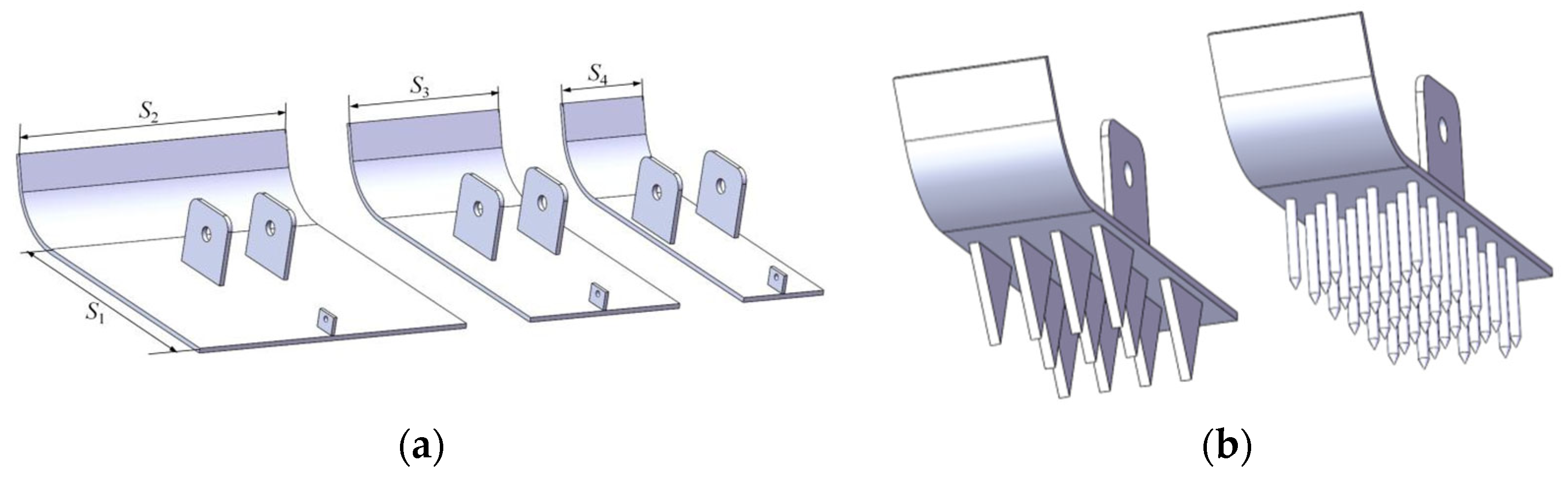
2.2.3. Reciprocating Weeding Shovel Design

This paper presents the design of a spike-tooth weeding shovel, primarily consisting of components such as a weeding plate, springs, and mounting pins, as depicted in Figure 4. The forward-bent front surface of the weeding plate minimizes soil resistance during operation and mitigates soil accumulation during reciprocating movements. The adjustment holes facilitate regulating the working height and the springs effectively stabilize the shovel’s posture amidst uneven terrain, ensuring consistent weeding depth. The length (S1) of the weeding plate is designed to be 215 mm, while the width (S2, S3, and S4) varies according to different strip planting spacings for soybeans and corn, with values of 250 mm, 140 mm, and 75 mm, respectively, as shown in Figure 5a. To enhance weeding efficiency, spike teeth are arranged on the underside of the weeding plate in either a blade-tooth [34,35] or comb-tooth [36,37] configuration, as illustrated in Figure 5b. Each weeding plate is equipped with either 3 rows of blade teeth or 12 rows of comb teeth, with subsequent optimization of tooth structures planned through EDEM simulations.
The reciprocating motion of the weeding shovel is achieved through an eccentric wheel, and the length of the weeding shovel’s oscillating rod and the eccentric distance of the eccentric wheel will determine the overlapping region of the reciprocating motion, which directly impacts the weeding efficacy. Figure 6 illustrates the schematic diagram of the reciprocating motion of the weeding shovel. Drawing from the experimental results of the reciprocating tine-type cultivator outlined in the “Agricultural Machinery Design Handbook” [38], when the oscillating amplitude of the swing rod is 140 mm and the length of the overlapping motion region is 10 mm, both optimal soil loosening and a high weeding rate can be achieved simultaneously. Consequently, this study designs the total oscillating amplitude for the reciprocating motion to be 140 mm. To ensure uniform weeding by the shovel, the forward and backward displacements under the oscillating states of the swing rod should be equal. The dimensions are designed as l1 = 225 mm, l2 = 440 mm, l3 = 100 mm, d = 50 mm, and BT = 45 mm. Using SolidWorks 2023, AI, A1I, and A2I values can be derived as 69.3 mm, 35.1 mm, and 98 mm, respectively. Based on trigonometric geometric functions, the eccentric distance MH is calculated to be 19.71 mm.
The eccentric roller bearing is mounted on the drive shaft of the implement, which is directly connected to the power take-off shaft of the towing tractor. The rotational speed of the tractor PTO shaft influences the reciprocation frequency of the swing lever, subsequently affecting the soil resistance experienced by the weed cutter and the soil disturbance rate. The implement is matched with a Dimagic 704 (Jiangsu Dimacchi Agricultural Equipment Technology Co., Ltd., Yangzhou, China) wheeled tractor, which features a PTO shaft with two rotational speed settings: 760 r/min and 540 r/min. Referring to Figure 6b, where the center of the eccentric hub, the center of the eccentric contour, and the lower endpoint of the swing lever are collinear, the Aronhold–Kennedy theorem (three-center theorem) is applied to analyze the instantaneous center of the structure. The swing lever, eccentric wheel, and frame are considered components 1, 2, and 3, respectively, with their respective velocity instant centers denoted as P12, P13, and P23. Since P12 and P13 are infinitely distant from P23, being tangent points to the center, it can be determined that the exact position of P12 is the center of the outer ring of the eccentric bearing. Because v P 12 is the coincidence point of the instantaneous velocities of components 1 and 2, the following kinematic relationships are established:
v P 12 = v 1 = v 2
v 1 = ω 1 P 13 P 12
v 2 = ω 2 P 23 P 12
ω L = ω M P 23 P 12 P 12 P 13
v L = ω L L
where v p 12 is the velocity at the instantaneous velocity coincidence point of components 1 and 2, m/s; v 1 and v 2 denote the absolute velocities of the instant centers of components 1 and 2, respectively, m/s; P12P13 is the distance between the instantaneous centers of the velocity of components 1 and 2 and those of components 1 and 3, mm; P12P23 is the distance between the instantaneous centers of the velocity of components 1 and 2 and those of components 2 and 3, mm; ωL is the angular velocity of the rocker arm rotation, rad/s; ωM denotes the angular velocity of the eccentric wheel rotation, rad/s; v L is the linear velocity at the end of the rocker’s arm, m/s; and L is the distance from the instant center of the rocker arm to its end, mm.
Given an eccentricity of 19.71 mm, h can be calculated as 39.42 mm, P12P13 as 540 mm, and P12P23 as 19.71 mm. When the rotational speeds of the tractor’s power take-off shaft are 760 r/min and 540 r/min, the horizontal relative velocities of the reciprocating hoe can be calculated as 1.57 m/s and 1.1 m/s, respectively.
During the reciprocating operation of the weeding shovel, the relationship between the absolute velocity, the horizontal relative velocity, and the forward speed of the machinery can be expressed as follows:
v B = v L v G
v Q = v L + v G
where v B is the backward velocity of the weeding shovel during the reciprocating operation, m/s; v Q is the forward velocity of the weeding shovel during the reciprocating operation, m/s; and v G denotes the forward speed of the machinery, m/s.

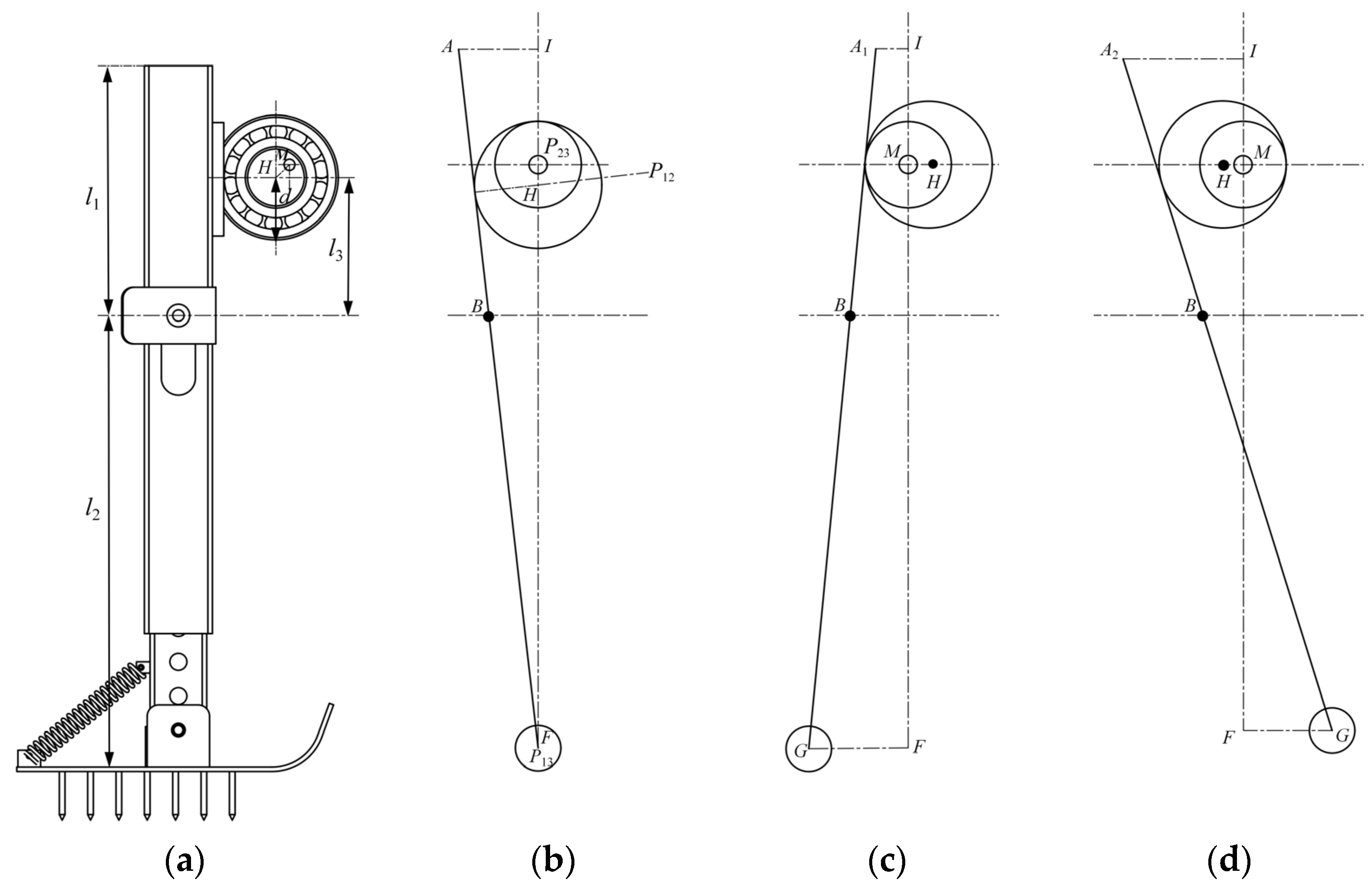
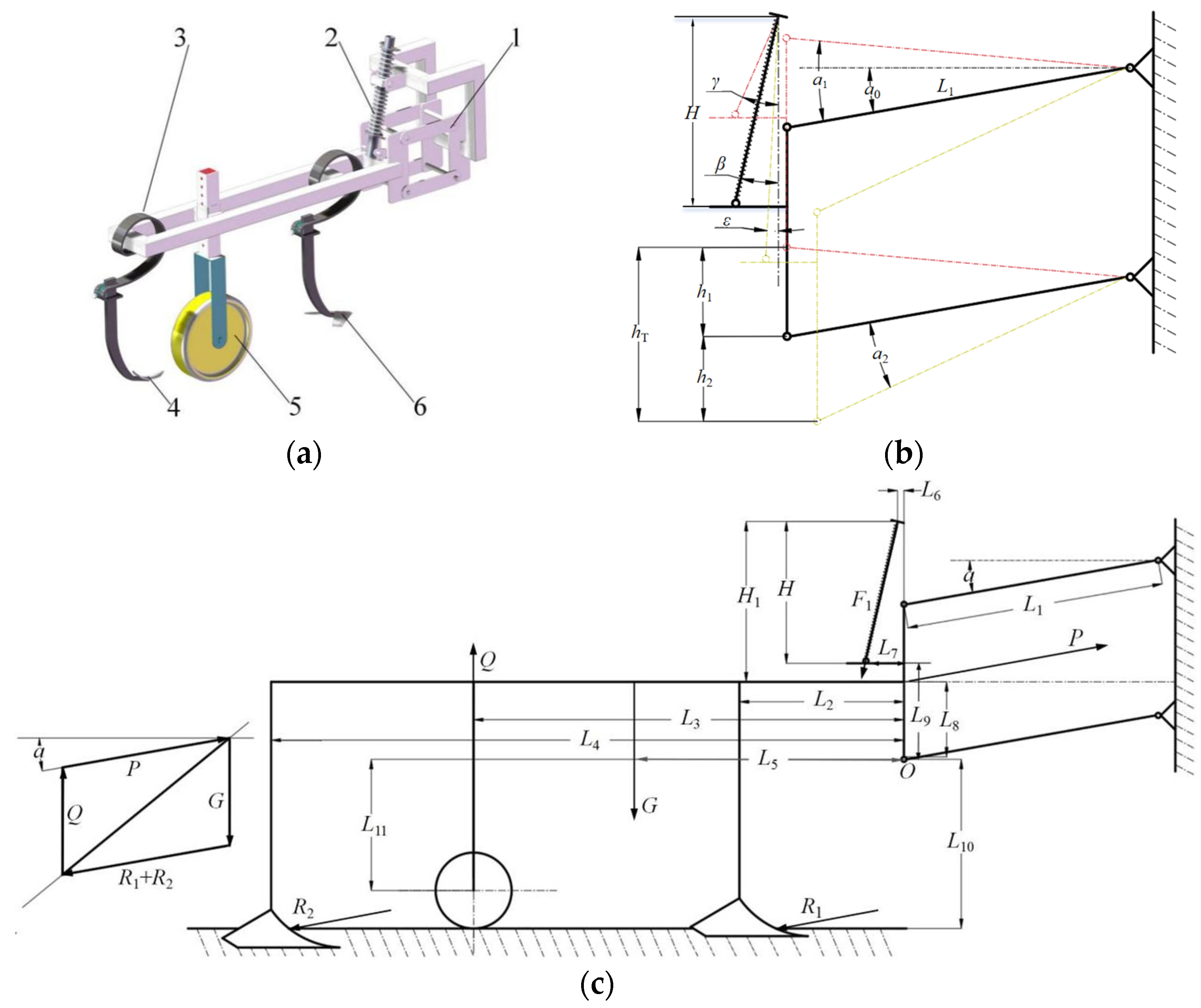
2.2.4. Design of the Adaptive Contouring Mechanism for Cultivation and Soil Loosening

As shown in Figure 7a, taking the working unit of the adaptive contouring mechanism for cultivation and soil loosening with a working width of 200 mm as an example, as shown in Figure 7a, this unit primarily consists of double-wing weeding shovels, double-pointed soil-loosening shovels, a parallel four-bar mechanism, and contour-following depth-limiting wheels. To ensure that the cultivating components attached via the S-shaped elastic shovel handle conform more precisely to the ground surface during operation and enhance the stability of the working depth, an adaptive contouring solution is employed that integrates contour-following depth-limiting wheels, springs, and the parallel four-bar mechanism.
Assuming the working depth of the components is W mm, the undulations of the working soil surface are approximated as a sine curve, with the maximum undulation height denoted as hF (mm), the horizontal length of the ground as E (mm), and the horizontal distance between the contour-following depth-limiting wheel and the weeding/soil-loosening shovel as r (mm). When the contour-following depth-limiting wheel is positioned in front, the distance is negative; conversely, when it is positioned behind, the distance is positive.
The formula for the ground curve can then be expressed as:
y D = W + h F sin π x E
The depth curve of the weeding shovel/loosening shovel operation is:
y c = h F sin ( π x E   π r E )
Finally, the real-time operation depth and the corresponding derivative are obtained as follows:
D = y D y 1 = W + h F sin π x E h F sin ( π x E   π r E )
D ˙ = h F π E cos π x E h F π E cos ( π x E π r E )
According to Equation (11), when r equals 0, the derivative of the working depth remains constant at 0, indicating that the working depth remains unchanged. In other words, the closer the distance between the contour-following depth-limiting wheel and the working component, the better the contour-following depth-limiting effect. However, since a minimal distance between them can easily lead to clogging, a contour-following depth-limiting wheel with a diameter of 304.8 mm is selected. Considering these factors, the wheel is installed between the double-wing weeding shovel and the double-pointed soil-loosening shovel, maintaining a distance of 420 mm and 320 mm from each, respectively.
The geometric relationship of the contour-following amount in the adaptive contouring mechanism for cultivation and soil loosening is illustrated in Figure 7b. Analysis reveals that the relationship between the up–down contouring amount, total contouring amount, and the lengths of the upper and lower bars in the four-bar linkage is as follows:
h 1 = L 1 ( sin a 0 + sin a 1 )
h 2 = L 1 sin ( a 0 + a 2 ) L 1 sin α
h T = h 1 + h 2 = L 1 ( sin a 1 + sin ( a 0 + a 2 ) )
where L1 is the length of the upper and lower bars in the parallelogram four-bar linkage, mm; h1 is the upper contouring amount of the parallelogram four-bar linkage, mm; h2 is the lower contouring amount of the parallelogram four-bar linkage, mm; a0 is the traction angle without a contouring amount at the designed working depth, °; a1 is the upper contouring traction angle at the minimum working depth, °; and a2 is the lower contouring traction angle at the maximum working depth, °.
Typically, the upper and lower contouring amounts for mid-tillage machines are both 50 mm, with limited upper and lower contouring traction angles of 15°. However, the contouring traction angle of this machine without contour-following is 10°, and the working depth ranges from 30 to 50 mm. Calculating hT as 180 mm and substituting it into Equation (14) yields L1 as 199.8 mm, resulting in a designed length of 200 mm for the upper and lower bars of the parallel four-bar mechanism.
During actual operation, due to the slight angle between the centerline of the spring and the connecting pin, this angle is considered constant for calculation purposes. Consequently, there exists a relationship between the elongation of the helical spring and the contour-following of the four-bar linkage as follows:
Δ l R = H c o s β H L 1 tan a 1 c o s γ
Δ l D = L 1 tan a 2 + H c o s ε H c o s β
where ∆lR is the variation in the helical spring during the upper contouring state of the parallel four-bar mechanism, mm; ∆lD is the variation in the helical spring during the lower contouring state of the parallel four-bar mechanism, mm; H is the vertical distance from the top of the helical spring to the end shim in the horizontal state, mm; β is the angle between the initial state helical spring and the vertical rod of the parallel four-bar mechanism, °; γ is the angle between the helical spring and the vertical rod of the parallel four-bar mechanism in the lifted working state, °; and ε is the angle between the helical spring and the vertical rod of the parallel four-bar mechanism in the lowered working state, °.
Based on the force diagram of the contouring scheme presented in Figure 7c, the force relationship within the contouring mechanism can be expressed as follows:
Upper contouring amount stage:
( R 1 + R 2 ) cos a 1 L 10 + P cos a 1 L 8 + Q L 3 = R 1 sin a 1 L 2 + R 2 sin a 1 L 4 + G L 5 + F 1 ( sin γ L 9 + cos γ L 7 )
Lower contouring amount stage:
( R 1 + R 2 ) cos a 2 L 10 + P cos a 2 L 8 + Q L 3 + F 1 ( sin ε L 9 + cos ε L 7 ) = R 1 sin a 2 L 2 + R 2 sin a 2 L 4 + G L 5
G + R 1 + R 2 + Q + P = 0
F 1 = k c Δ l
k c = G c d c 4 8 D c 3 N c
where F1 is the supporting force applied to the parallel four-bar mechanism, N; G denotes the self-weight of the cultivating and loosening mechanism, N; R1 is the soil resistance encountered by the double-wing shovel, N; R2 is the soil resistance encountered by the loosening shovel, N; P is the traction force provided by the tractor, N; kc is the elastic coefficient of the spring; Gc is the stiffness coefficient of the spring, N/mm; Nc is the number of coils in the spring; Dc is the mean diameter of the spring, mm; and dc is the wire diameter of the spring, mm.
Based on the actual conditions of the implement, β is set at 13°, H at 240 mm, H1 at 270 mm, L1 at 200 mm, L2 at 205 mm, L3 at 525 mm, L4 at 945 mm, L5 at 472.5 mm, L6 at 18 mm, L7 at 83.5 mm, L8 at 97.5 mm, L9 at 127.5 mm, L10 at 587.5 mm, and L11 at 430 mm. The traction force P is 20 N, and the self-weight G is 103.5 N. Through SolidWorks simulations under two extreme conditions, γ and ε are determined to be 23.58° and 3°, respectively. Substituting these values into Equations (15) and (16), the maximum Δ l R is 42.97 mm and Δ l R is 47.68 mm. According to Equations (17)–(19), the spring working loads under the upper and lower limit contouring conditions are 120 N and 170 N, respectively. Incorporating these into Equations (20) and (21), it is concluded that the required elastic coefficient of the matching spring must be greater than 3.56. Consequently, the selected spring parameters are a stiffness coefficient of 8000 N/mm, several coils of 12, a wire diameter of 5 mm, and a mean diameter of 22 mm.

2.3. Discrete Element Simulation Analysis of the Weeding Shovel–Soil Interaction

The tooth profiles on the bottom of the weeding plate in Figure 5, along with the rotational speed of the PTO and the machine’s forward speed, influence the soil resistance encountered by the weeding shovel and the degree of soil disturbance. To ascertain the optimal design combination and further refine the design, this study utilizes EDEM 2023 to conduct discrete element simulation, taking a 75 mm model of the weeding plate as an example. The plate-teeth configuration involves a staggered arrangement of 3 teeth in the middle row and 4 teeth in the front and rear rows, respectively. The comb-teeth arrangement comprises six sets, each with two rows (4 teeth in the front row and 3 teeth in the rear row) arranged in an alternating pattern. Both the plate-teeth thickness and the comb-teeth diameter are set at 5 mm, with a height of 50 mm and an adjacent spacing of 15 mm. Considering the relative speeds of the weeding shovel’s reciprocal motion at PTO shaft rotational speeds of 760 r/min and 540 r/min, derived from previous analyses, the operational effects of the two structural configurations of the weeding shovel are evaluated at tractor speeds of 2.5 km/h, 3 km/h, 3.5 km/h, and 4 km/h.
Based on the calibration results of the slump test for soil in the Lixiahe region [39,40], the soil type in this area is classified as clay loam, with an average plow layer depth of 0–100 mm and an average density of 1.5966 g·cm−3. The soil comprises 13% sand particles ranging from 1.5 to 0.1 mm in size, 45.8% silt-clay particles ranging from 0.1 to 0.05 mm, and 44.1% very fine sand particles smaller than 0.005 mm. A soil model measuring 150 mm wide, 450 mm long, and 100 mm deep is established, with particles of 2 mm, 1 mm, and 0.6 mm radii generated according to the actual particle size distribution proportions. Relevant soil coefficients and weeding shovel material coefficients are listed in Table 2.
To better evaluate the effect of the weeding operation, the simulation employed the Hertz–Mindlin Bonding model for particle–particle contact and the Hertz–Mindlin model for particle–geometry contact. The total duration of the simulation was 0.148 s, and the data saving interval was set at 0.001 s.

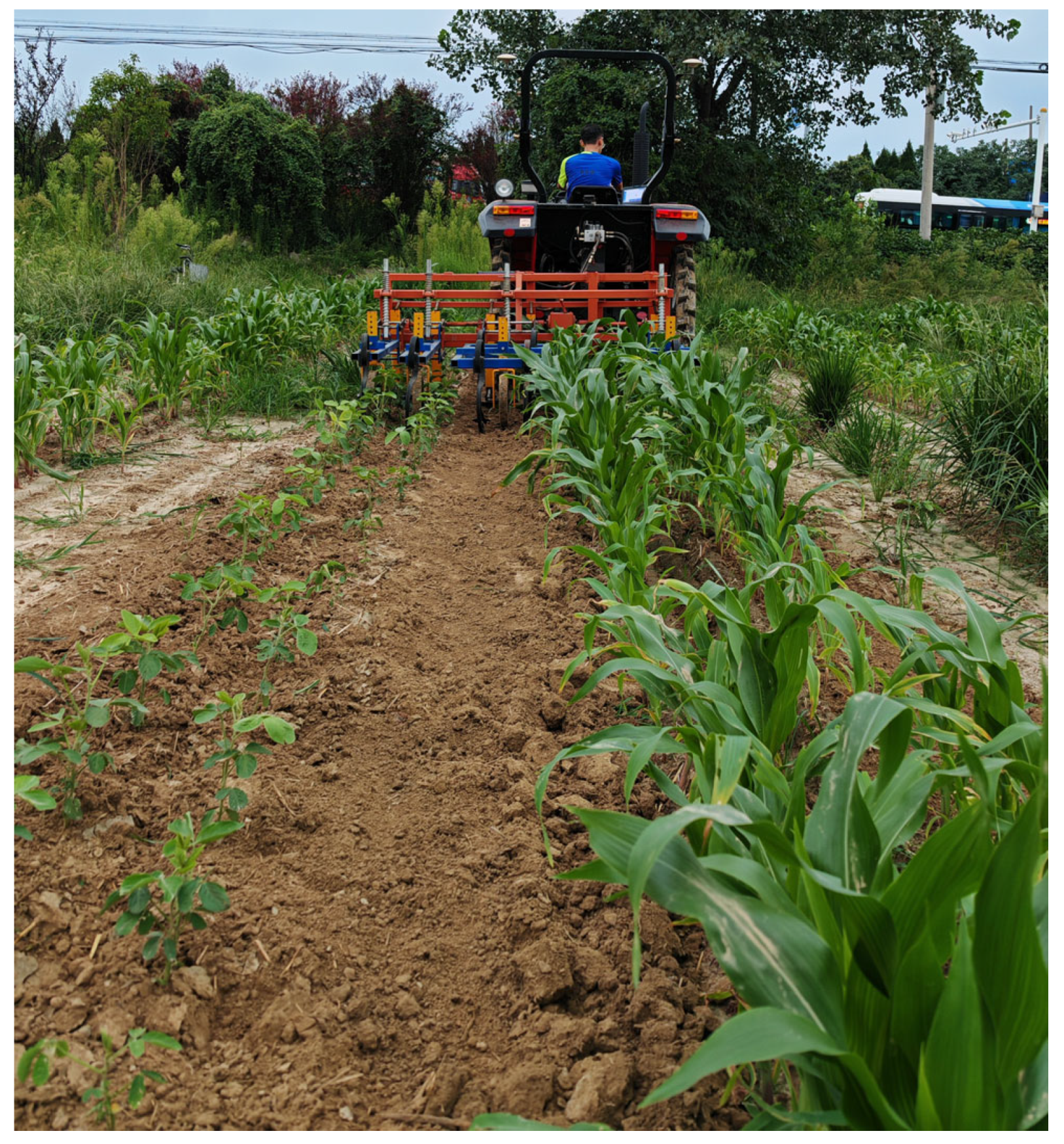
2.4. Field Experiment

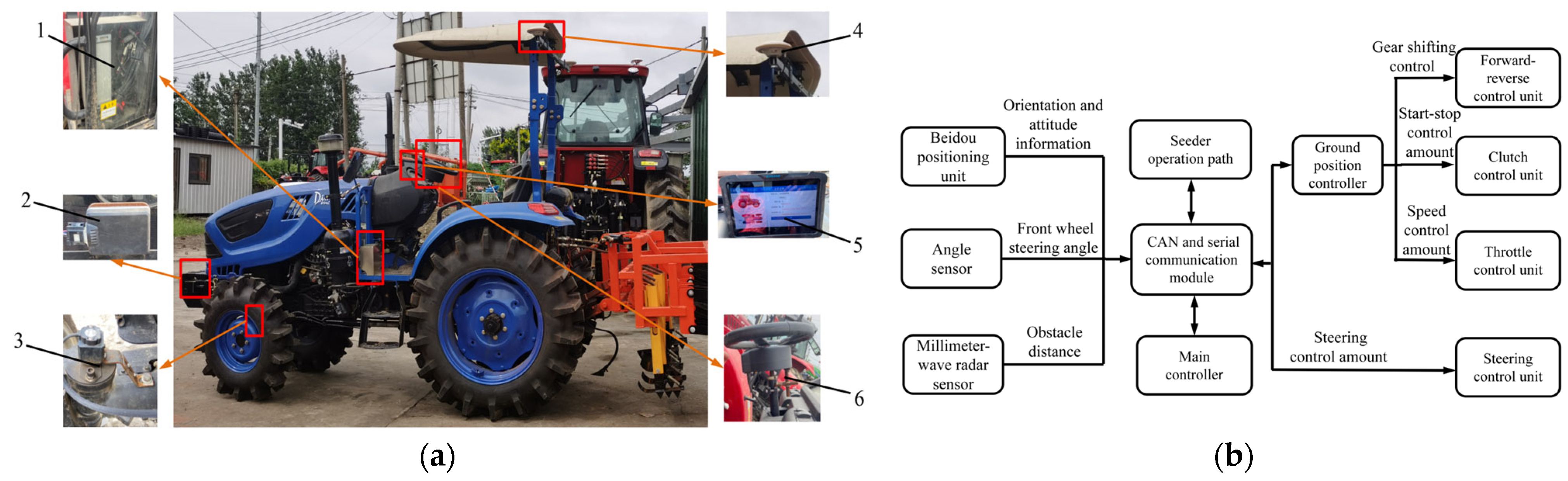
2.4.1. Tractor Modification

This study is based on the automation modification of a Dimagic 704 tractor (Jiangsu Dimacchi Agricultural Equipment Technology Co., Ltd., Yangzhou, China), as depicted in Figure 8a. The modification employs an autonomous driving system developed by Yangzhou University, which features a satellite-based Beidou navigation system [41]. This system includes a primary and a secondary satellite antenna, a tablet computer, an electronic steering wheel, and an angular measurement device. The primary and secondary satellite navigation antennas are installed symmetrically on either side of the tractor’s rear support bracket to capture the implement’s positional and orientation data. The tablet computer is mounted on a bracket in front of the driver’s seat and integrates navigation and communication modules, facilitating operational path planning. The angular measurement device is positioned on the left side of the tractor’s front steering axle to monitor the steering angle continuously. At the same time, the torque motor is installed on the steering column using a spline sleeve. The Beidou navigation system for weeder application follows a precise navigational control process, as illustrated in Figure 8b. By leveraging the operational path data from the corresponding seeder and incorporating it into path planning, the system enables the towed weeder to perform precision weeding with an accuracy of ±2.5 cm.

2.4.2. Field Experiment Design

The field experiment was conducted in the experimental field of Yangzhou University in Jiangdu (119.512° E, 32.562° N), with a soil moisture content of 20.85% and a soil average firmness of 913.76 kPa. The soybean variety used was Tongdou No. 7, and the corn variety was Austian Nuomi 75. The planting date was 12 June 2024. The corn plants were spaced 14 cm apart with a sowing depth of 5 cm, while the soybeans were planted 12 cm apart at a depth of 3 cm. To validate the operational performance of the machine, we conducted weeding operations 15 days post-sowing. These operations were performed using the weeding machine at its optimal motion parameters and with varying working depths. The experimental groups are detailed in Table 3.
The test area for each of the six experimental groups was 0.0135 hm2. Ten measuring points, each with an area of 1.9 m2, were randomly selected in each group. At each measuring point, the number of soybeans, corn, and weeds was recorded both before and after the test. The experiment indexes of the mechanical weeding effect are weeding rate C (%) and seedling injury rate S (%), and the calculation formula is:
C = T I T × 100 %
S = N B × 100 %
where T is the total number of weeds between the rows, I is the total number of remaining weeds in the rows after mechanical weeding, N is the number of injured soybean or corn seedlings bent, cut, and uprooted in the test area after weeding, and B is the number of crop seedlings in the test area.

3. Results

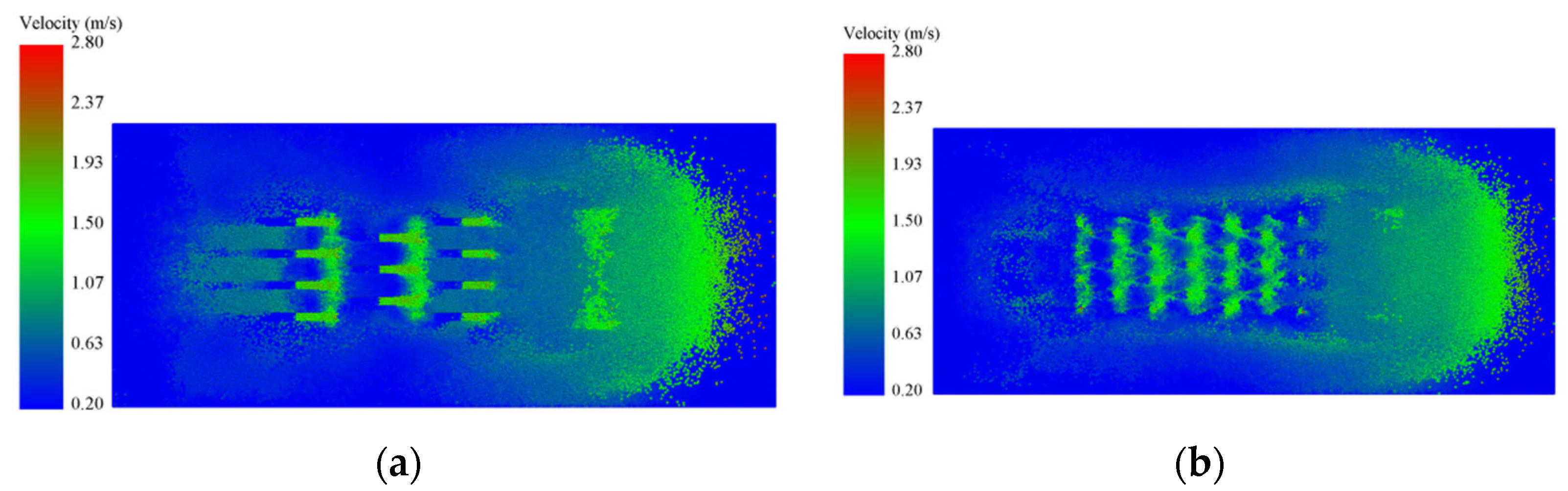
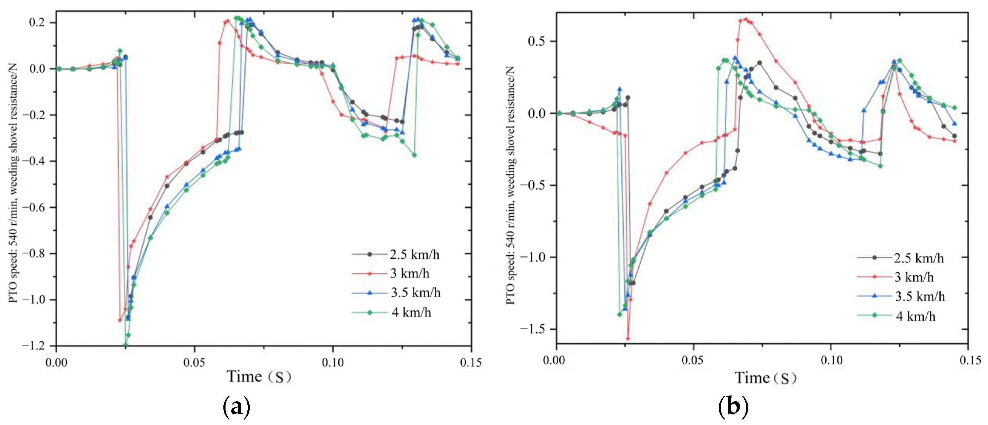
3.1. Simulation Results and Analysis

The disturbance of the weeding shovel induces the motion of soil particles, thus enabling the determination of the soil disturbance level based on the number of moving particles [42]. Additionally, the statistics of disturbed particles and the soil resistance encountered by the weeding shovel can be directly exported from the software. During analysis, priority is given to comparing the soil disturbance rates caused by the weeding shovel, followed by considering the magnitude of soil resistance experienced by the weeding shovel.
To facilitate comparison, a cross-sectional analysis of the weeding shovel is conducted from a top–down perspective. With the velocity gradient of soil particle movement set at 0.2–2.8 m/s, Figure 9 illustrates the velocity contours of soil particles for both blade-toothed and comb-toothed weeding shovels, operating at a forward speed of 3 km/h and a PTO shaft rotational speed of 540 r/min. By combining these results with the statistics on disturbed particles (Table 4) and the resistance applied to the weeding shovel, this study concludes that the operational performance of the blade-toothed weeding shovel significantly surpasses that of the comb-toothed design.
On this basis, further simulation analysis was conducted on the blade-type weeding shovel under different machine forward speeds and PTO shaft rotational speeds. By combining the nephogram of particle velocity in Figure 10 with the particle statistical analysis in Table 5, the results indicate that at the same forward speed, the soil disturbance caused by the weeding shovel is greater at a PTO shaft rotational speed of 760 r/min compared to 540 r/min. At both PTO speeds, when the machine’s forward speed reaches 3.5 km/h, the number of disturbed particles and the soil disturbance rate are the highest.
Figure 11 illustrates the simulation results of the resistance encountered by the weeding shovel, while Table 6 presents the mean and maximum absolute values of the corresponding resistance under several scenarios. A combined analysis of these two sources reveals that when the rotational speed of the PTO shaft is set at 540 r/min, the initial downward penetration of the weeding shovel into the soil experiences negligible resistance (approximately 0 N). Subsequently, as the hoe moves forward, the resistance in the opposite direction of motion increases dramatically. Due to the reciprocating motion of the weed hoe, it reverses direction at approximately 0.055 s, where it begins to experience resistance in the positive direction of motion, which rapidly intensifies at around 0.065 s. This process then repeats cyclically. Under these conditions, the relationship between the forward speed of the machine and the operational resistance encountered by the weed hoe is as follows: 4 km/h > 3.5 km/h > 2.5 km/h > 3 km/h. In contrast, when the PTO shaft rotational speed is 760 r/min, the reciprocating speed of the weeding shovel accelerates, shortening the time required to complete the same operational cycle. The positive and negative resistances increase, yet they still adhere to the same change rule. Under these conditions, the relationship between the machine’s forward speed and the operational resistance of the weeding shovel reverses, becoming 3 km/h > 4 km/h > 2.5 km/h > 3.5 km/h.
The comprehensive comparison shows that, under the condition of using the blade-tooth structure, no matter whether the rotational speed of the power output shaft is 540 r/min or 760 r/min, and when the forward speed of the machine is 3.5 km/h, the soil resistance does not change significantly while ensuring maximum soil disturbance, making it the optimal parameter combination with the best working performance.

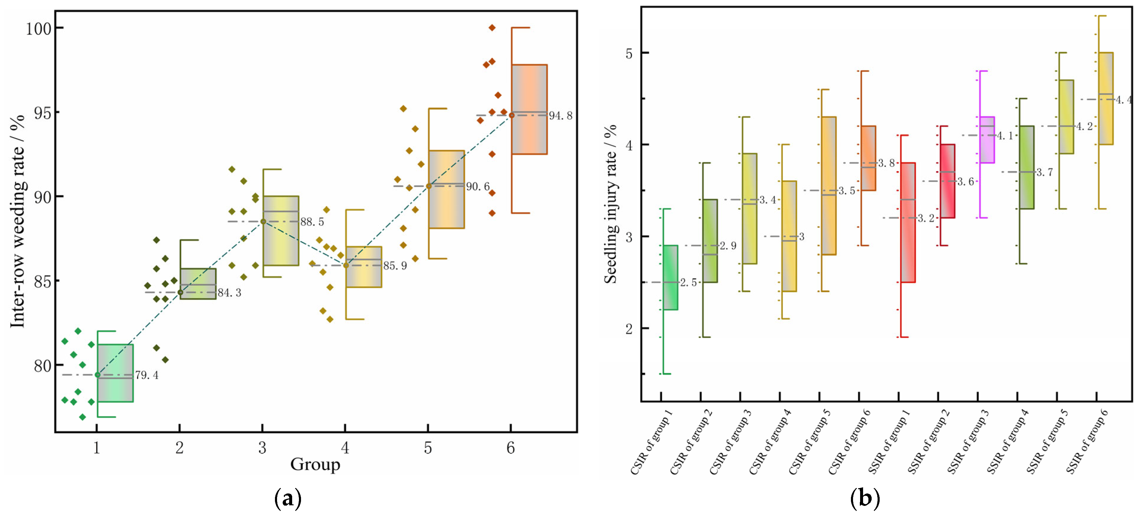
3.2. Field Experiment Results and Analysis

Figure 12a illustrates the inter-row weeding rates for different experimental groups. In contrast, Figure 12b presents the corn seedling injury rate (CSIR) and soybean seedling injury rate (SSIR) for each group separately. Weeding control effectiveness before and after treatment is shown in Figure 13. There was no obvious weed residue in the operation area, and the damage to the soybeans and corn was light, which meets the agronomic requirements of weed control in soybean and corn fields and also shows that the machine performed well.
Variance analysis on the inter-row weeding rate and seedling injury rate under various operating depths was conducted using Design-expert software 13, with a significance level α set at 0.05. When the rotational speed of the PTO shaft was either 540 r/min or 760 r/min, the p-value for both the inter-row weeding rate and the seedling injury rate was less than 0.05, indicating that the operating depth significantly impacted both the inter-row weeding rate and the seedling injury rate at these two PTO shaft rotational speeds. Moreover, both parameters gradually increased with the increase in operating depth. These trends can be explained by the fact that, at shallower depths, the weed hoe may fail to sever or uproot the deeply rooted weeds. As the operating depth increases, the weed removal effect improves, but so does the degree of soil disturbance, potentially uprooting some shallowly rooted crops.
Table 7 presents the weeding and seedling injury rates at different PTO shaft rotational speeds when the working depth is 3 to 5 cm. There is a positive correlation between the rotational speed of the PTO shaft and both the inter-row weeding rate and the seedling injury rate. According to Formulas (6) and (7), the relative speed of the reciprocating weed hoe increases with the PTO shaft’s rotational speed, enhancing weed removal effectiveness through more vigorous cutting action. However, this also leads to excessive soil loosening around crop roots, elevating the probability of crop lodging.
Under identical experimental conditions, the seedling injury rate for soybeans was consistently higher than that for corn. One reason is that soybeans have narrower row spacing, which requires higher precision in machine alignment during operations. Additionally, during the early weed control period, soybeans’ root systems are generally shallower than those of corn, making soybeans more susceptible to lodging when the soil is disturbed. Ultimately, at a PTO shaft rotational speed of 760 r/min, the average inter-row weeding rate reached 90.4%, with a corn seedling injury rate of 3.5% and a soybean seedling injury rate of 4.2%. Compared to a PTO shaft rotational speed of 540 r/min, this represents a 7.6% improvement in weed removal performance while maintaining a relatively low seedling injury rate, indicative of superior operational performance.

4. Discussion

This study designed an inter-row weeding machine applied in SCSCP that employs a synergistic approach using multiple mechanical weeding components to achieve effective weeding. The front row of the machine is equipped with a reciprocating weeding shovel, which disturbs the 0–50 mm soil layer, cutting and uprooting weed roots. This is followed by a secondary weeding and shallow tilling operation in the 50–80 mm soil layer using an adaptive contouring mechanism for cultivation and soil loosening at the rear. The machine demonstrated excellent operational effectiveness, with a weeding efficiency superior to that of existing dryland weeding machinery [12,14,15,16,17,18,19].
The soil disturbance caused by the weeding shovel determines the overall weeding efficiency, and the relative velocity during the reciprocating motion in the forward and backward directions directly affects the soil disturbance. This study calculated the relative motion speed of the weeding shovel for a 70-horsepower tractor operating at a PTO shaft rotational speed of 540 r/min, corresponding to reciprocating speeds of 1.57 m/s and 1.1 m/s, respectively. When the machine’s forward speed exceeds or approaches the reciprocating speed, the reciprocating effect is insufficient, reducing the soil disturbance caused by the weeding shovel. This conclusion was effectively validated through discrete element method simulations conducted in this study.
In each group of field trials, with one-row change, the machine completed weeding operations over an area of 0.0135 hm2. However, the crop seedling injury rate at the first two measuring points after changing rows was often higher than at other points. This is likely due to the narrow row spacing of soybean and corn planting as mandated in the Huang Huai Hai region, making it easier for the edges of the weeding components to come into contact with crop rows during the row-changing process. This issue could be addressed by improving the machine’s navigation system or planning areas at field edges to allow space for turning agricultural machinery.
Although this study demonstrated the machine’s excellent weeding performance, no comparative experiments were conducted to assess crop yields between mechanical and chemical weeding methods. Some previous studies suggest that mechanical weeding, in addition to controlling weeds, loosens the soil around crop roots, potentially promoting crop growth. Compared to the currently prevalent chemical weeding methods, mechanical weeding may increase plant height and yield, sometimes equaling or even surpassing chemical methods [27,29]. This issue will be explored in future trials.

5. Conclusions

(1)
An inter-row weeding machine designed explicitly for SCSCP has been developed. This weeder employs a multi-layered mechanical weeding approach that integrates reciprocating weeding shovels, double-wing weeding shovels, and double-pointed soil-loosening shovels. This configuration ensures effective weed control while simultaneously loosening the soil, aligning with the agronomic requirements of SCSCP.
(2)
A reciprocating motion mechanism has been designed, featuring a weed shovel swing amplitude of 140 mm, an eccentric wheel with a contoured radius of 50 mm, and an eccentricity of 19.71 mm. Mathematical modeling and mechanical analysis were conducted for the adaptive contour-following mechanism based on practical considerations. Consequently, a parallelogram linkage mechanism with upper and lower link lengths of 200 mm was selected, complemented by a contour-limiting depth wheel with a diameter of 304.8 mm. The contour-following solution incorporates a spring with a stiffness coefficient of 8000 N/mm, 16 coils, a wire diameter of 5 mm, and a central diameter of 22 mm.
(3)
Through a combination of discrete element simulations and field trials, the tooth profile of the reciprocating weeding shovel was optimized, and the optimal operating power conditions were determined. Under the optimal working combination of a blade-tooth weeding structure, a forward speed of 3.5 km/h, and a power take-off shaft speed of 760 r/min, the weeding shovel achieved the best soil disturbance effect with relatively low working resistance. It was confirmed that in conditions of operation at a depth of 3–5 cm, the average inter-row weeding rate of the machine reached 90.4%, with a corn seedling injury rate of 3.5% and a soybean seedling injury rate of 4.2%. The results demonstrate that this weeding machine exhibits excellent operational performance, fulfilling the technical requirements for mechanical weeding in soybean–corn intercropping systems.

Author Contributions

Conceptualization, Z.T. and X.X.; methodology, Z.T., X.X., Y.S. and R.Z.; validation, Z.T., X.X., Y.S. and Y.W.; formal analysis, Z.T., Y.S., B.Z. and Y.W.; investigation, Z.T., Y.S., B.Z. and Y.W.; data curation, Z.T. and X.X.; writing—original draft preparation, Z.T.; writing—review and editing, Z.T. and X.X.; visualization, X.X. and R.Z.; supervision, X.X. and R.Z.; project administration, B.Z. and R.Z.; funding acquisition, X.X. and R.Z. All authors have read and agreed to the published version of the manuscript.

Funding

This research was funded by the Jiangsu Modern Agricultural Machinery Equipment and Technology Demonstration and Promotion Project (NJ2023-22) and the High-End Talent Support Program of Yangzhou University.

Data Availability Statement

The original contributions presented in this study are included in the article. Further inquiries can be directed to the corresponding author.

Acknowledgments

The authors would like to thank the technical support of their teacher and supervisor. We also appreciate the assistance provided by team members during the experiments. Moreover, we would like to thank Yangzhou Huilong Machinery Manufacturing Co., Ltd. for manufacturing the device. Additionally, we sincerely appreciate the work of the editor and the reviewers of the present paper.

Conflicts of Interest

The authors declare no conflicts of interest.

References

  1. Luo, X.; Liao, J.; Hu, L.; Zang, Y.; Zhou, Z. Improving agricultural mechanization level to promote agricultural sustainable development. Trans. Chin. Soc. Agric. Eng. 2016, 1, 1–11. [Google Scholar]
  2. Wei, X.; Zhu, M.; Liao, Y. Promoting agricultural engineering to ensure food security in China. Sci. Technol. Rev. 2023, 20, 5–19. [Google Scholar]
  3. Yang, J.; Huang, Z.; Zhang, X.; Reardon, T. The rapid rise of cross-regional agricultural mechanization services in China. Am. J. Agric. Econ. 2013, 95, 1245–1251. [Google Scholar] [CrossRef]
  4. Zhou, X.; Ma, W.; Li, G.; Qiu, H. Farm machinery use and maize yields in China: An analysis accounting for selection bias and heterogeneity. Aust. J. Agric. Resour. Econ. 2020, 64, 1282–1307. [Google Scholar] [CrossRef]
  5. Li, Y.; Yang, Y.; Li, J.; Si, W. Development trends and policy suggestions of soybean industry in 2024. Soybean Sci. Technol. 2024, 1, 1–5. [Google Scholar]
  6. Huang, Q.; Kang, Y.; Zhang, D. Impact of trade disputes between China and the United States on Chinese corn production and consumption. J. Henan Agric. Univ. 2024, 58, 318–324. [Google Scholar]
  7. Du, J.B.; Han, T.F.; Gai, J.Y.; Yong, T.W.; Sun, X.; Wang, X.C.; Yang, F.; Liu, J.; Shu, K.; Liu, W.G.; et al. Maize-soybean strip intercropping: Achieved a balance between high productivity and sustainability. J. Integr. Agric. 2018, 17, 747–754. [Google Scholar] [CrossRef]
  8. Luo, Y. Screening and Evaluation of Safe Compatibility Herbicide Formulations for Soybean and Corn; Jilin Agricultural University: Changchun, China, 2024. [Google Scholar]
  9. Taylor, E.C.; Renner, K.A.; Sprague, C.L. Organic weed management in field crops with a propane flamer and rotary hoe. Weed Technol. 2012, 26, 793–799. [Google Scholar] [CrossRef]
  10. Sharma, B.; Singh, S.R.; Gupta, S.; Shrivastava, M.K.; Verma, S. Improving efficiency and reduction in drudgery of farm women in weeding activity by twin wheel hoe. Indian Res. J. Ext. Educ. 2016, 15, 76–80. [Google Scholar]
  11. Shen, S.; He, Y.; Tang, Z.; Dai, Y.; Wang, Y.; Ma, J. Development of an orchard mowing and sweeping device based on an ADAMS–EDEM simulation. Agriculture 2023, 13, 2276. [Google Scholar] [CrossRef]
  12. Melander, B. Optimization of the adjustment of a vertical axis rotary brush weeder for intra-row weed control in row crops. J. Agric. Eng. Res. 1997, 68, 39–50. [Google Scholar] [CrossRef]
  13. Meyers, J.M.; Miles, J.A.; Faucett, J.; Ira Janowitz, M.F.; Tejeda, C.D.; Weber, E.; Smith, R.; Garcia, L. Priority risk factors for back injury in agricultural field work vineyard ergonomics. J. Agromed. 2002, 8, 39–54. [Google Scholar] [CrossRef]
  14. Kwon, T.H.; Kim, J.; Lee, C.; Kang, T.G.; Lee, B.M.; Rhee, J.Y. A study on rotary weeding blade installation angle for reduction of hand vibration in working type cultivator. J. Biosyst. Eng. 2014, 39, 11–20. [Google Scholar] [CrossRef]
  15. Wang, B. The Design and Experimental Research of Weeding Plant between Soybean Seedlings; Northeast Agricultural University: Harbin, China, 2019. [Google Scholar]
  16. Han, B.; Guo, C.; Gao, Y.; Liu, Q.; Sun, S.; Dong, X. Design and experiment of soybean intra-row weeding monomer mechanism and key components. Trans. Chin. Soc. Agric. Mach. 2020, 51, 112–121. [Google Scholar]
  17. Richard, D.; Leimbrock-Rosch, L.; Keßler, S.; Stoll, E.; Zimmer, S. Soybean yield response to different mechanical weed control methods in organic agriculture in Luxembourg. Eur. J. Agron. 2023, 147, 126842. [Google Scholar] [CrossRef]
  18. Quan, L.; Jiang, W.; Li, H.; Wang, Q.; Chen, L. Intelligent intra-row robotic weeding system combining deep learning technology with a targeted weeding mode. Biosyst. Eng. 2022, 216, 13–31. [Google Scholar] [CrossRef]
  19. Cordill, C.; Grift, T.E. Design and testing of an intra-row mechanical weeding machine for corn. Biosyst. Eng. 2011, 110, 247–252. [Google Scholar] [CrossRef]
  20. Hemming, J.; de Jong, H.; Struik, L.; van Meer, J.; Van Henten, E.J. Field performance evaluation method for a machine vision based intra row hoeing machine. Proc. Eur. Conf. Agric. Eng. AgEng 2018, 2018, 188–196. [Google Scholar]
  21. Bawden, O.; Kulk, J.; Russell, R.; McCool, C.; English, A.; Dayoub, F.; Lehnert, C.; Perez, T. Robot for weed species plant—Specific management. J. Field Robot. 2017, 34, 1179–1199. [Google Scholar] [CrossRef]
  22. Bai, Z.; Li, H.; Bai, H.; Wan, Y.; Liu, N.; Liu, D.; Li, Z.; Jin, C. Control efficacy on weeds and safety of pyroxasulfone and thifensulfuron-methyl in soybean-corn intercropping field. Agrochemicals 2024, 63, 73–78. [Google Scholar]
  23. Wang, X.; Xi, X.; Chen, M.; Huang, S.; Jin, Y.; Zhang, R. Development status of soybean and corn ribbon compound planting technology and equipment. Jiangsu Agric. Sci. 2023, 51, 36–45. [Google Scholar]
  24. Li, R.; Luo, Y.; Li, S.; Xie, R.; Zheng, H.; Wang, H.; Liu, W.; Zheng, J. Effects of mechanical and chemical weed control on maize and soybean in no-tillage with straw mulch. J. Northeast Agric. Sci. 2019, 44, 1–6. [Google Scholar]
  25. Zhou, Z.; Hao, L.; Gan, L.; Lu, H.; Wang, C.; Li, R.; Yu, Z. Field experiment effect of chemical herbicide under belt compound planting mode of soybean and corn. Shaanxi J. Agric. Sci. 2023, 69, 71–74. [Google Scholar]
  26. Yang, Y. The Design and Experimental Research on Working Depth Control System of Soybean Intra-row Mechanical Weeding; Northeast Agricultural University: Harbin, China, 2018. [Google Scholar]
  27. Wang, W. Design and Experimental Study on Mechanical Weeding Device of the Ripple Maize; Northeast Agricultural University: Harbin, China, 2018. [Google Scholar]
  28. Chandel, N.S.; Chandel, A.K.; Roul, A.K.; Solanke, K.R.; Mehta, C.R. An integrated inter-and intra-row weeding system for row crops. Crop Prot. 2021, 145, 105642. [Google Scholar] [CrossRef]
  29. Jiao, J.; Hu, L.; Chen, G.; Tu, T.; Wang, Z.; Zang, Y. Design and experiment of an inter-row weeding equipment applied in paddy field. Trans. Chin. Soc. Agric. Eng. 2023, 39, 1–12. [Google Scholar]
  30. Bručienė, I.; Buragienė, S.; Šarauskis, E. Weeding Effectiveness and Changes in Soil Physical Properties Using Inter-Row Hoeing and a Robot. Agronomy 2022, 12, 1514. [Google Scholar] [CrossRef]
  31. Gao, C.; Li, X.; Liu, Y.; Jia, R.; Zhang, H.; Liu, J. Processes and Modelling of Soil Compaction in Farmland: A Review. Soils 2024, 56, 1–9. [Google Scholar]
  32. O’Sullivan, M.F.; Simota, C. Modeling the environmental impacts of soil compaction: A review. Soil Tillage Res. 1995, 35, 69–84. [Google Scholar] [CrossRef]
  33. Xi, X.; Wang, X.; Jin, Y.; Zhang, Y.; Zhu, Z.; Zhang, B.; Qu, J.; Zhang, R. A Compound Seeding Apparatus. China Patent CN219068883U, 26 May 2023. [Google Scholar]
  34. Wang, Y.; Xi, X.; Chen, M.; Shi, Y.; Zhang, Y.; Zhang, B.; Qu, J.; Zhang, R. Design of and Experiment on Reciprocating Inter-Row Weeding Machine for Strip-Seeded Rice. Agriculture 2022, 12, 1956. [Google Scholar] [CrossRef]
  35. Jiang, Y.; Qi, L.; Gong, H.; Liu, C.; Tao, M.; Hu, X.; Chen, Q. Design and experiment of pneumatic paddy intra-row weeding device. J. South China Agric. Univ. 2020, 41, 37–49. [Google Scholar]
  36. Jia, H.; Li, S.; Wang, G.; Liu, H. Design and experiment of seedling avoidable weeding control device for intertillage maize (Zea mays L.). Trans. Chin. Soc. Agric. Eng. 2018, 34, 15–22. [Google Scholar]
  37. Gagliardi, L.; Luglio, S.M.; Peruzzi, A.; Fontanelli, M.; Frasconi, C.; Raffaelli, M. Comparative Analysis of the Performance of a Chain Mower and Tools That Perform Under-Row Weed Control with Tillage in the Vineyard. Agronomy 2024, 14, 206. [Google Scholar] [CrossRef]
  38. Zhang, X. Middle Tillage Fertilization Machinery. In Agricultural Machinery Design Manual; China Agricultural Science and Technology Press: Beijing, China, 2017; Volume 1, p. 565. [Google Scholar]
  39. Wang, W. Deep Rotary Tillage and Mixing Process for Soil-Straw Based on Biaxial Cutting Principle under Rice-Wheat Rotation System; Yangzhou University: Yangzhou, China, 2023. [Google Scholar]
  40. Pan, H. Design and Parameter Optimization of Double Axis Rotary Tillage Stubble Extinguisher Based on Discrete Element Method; Jiangsu University: Zhenjiang, China, 2020. [Google Scholar]
  41. Shi, Y.; Xi, X.; Wu, F.; Zhang, R.; Jin, Y.; Gong, J. Design and experimental study on automatic driving system of motor type agricultural machinery based on Beidou navigation. J. Northeast Agric. Univ. 2019, 4, 88–96. [Google Scholar]
  42. Jiao, J.; Hu, L.; Chen, G.; Chen, C.; Zang, Y. Development and Experimentation of Intra-Row Weeding Device for Organic Rice. Agriculture 2024, 14, 146. [Google Scholar] [CrossRef]
Figure 1. Schematic diagram of the compound planting of 2 rows of corn and 4 rows of soybeans.
Agronomy 14 02136 g001
Figure 2. Structural diagram of mechanized inter-row weeder for SCSCP. 1. Transmission box 2. Ditch shovel 3. Ditch Shaper 4. Transverse electrohydraulic drive device 5. Weeding shovel 6. Eccentric mechanism 7. Suspension lift device 8. Double-wing weeding shovel 9. Contour wheel 10. Double-pointed loose soil shovel 11. Elastic shovel handle 12. Spring 13. Frame.
Agronomy 14 02136 g002
Figure 3. Schematic diagram of operating mode and movement pattern for the weeding machine used in SCSCP.
Agronomy 14 02136 g003
Figure 4. Structure drawing of the weeding shovel. 1. Installation hole 2. Regulating hole installation hole 3. Spring 4. Weeding plate 5. Mount pin 6. Eccentric wheel orbit.
Agronomy 14 02136 g004
Figure 5. Schematic diagram of the weeding plate structure: (a) Three types of weeding plates; (b) Blade-tooth type and comb-tooth type weeding structures.
Agronomy 14 02136 g005
Figure 6. Brief diagram of the reciprocating movement of the weeding shovel: (a) Vertical state; (b) The collinear condition of three points; (c) Back swing state; (d) Front swing state. M is the center of the outer ring of the eccentric roller bearing; H is the center of the contour of the eccentric cam; I and F are the positions of the two vertices of the oscillating rod when it is in a vertical state; A1 and G are the positions of the two vertices of the oscillating rod when it swings backward to its farthest distance; A2 and G are the positions of the two vertices of the oscillating rod when it swings forward to its farthest distance; d is the distance from the hub center of the eccentric cam to the oscillating rod when the weeding spade is in a vertical state; BT is the perpendicular distance from the fixed pin on the bottom frame to the center of the outer ring of the eccentric roller bearing; MH is the eccentricity of the eccentric cam; l1 is the distance between the bottom frame and the top frame; l2 is the distance from the bottom frame to the ground; and l3 is the distance from the hub center of the eccentric cam to the bottom frame.
Agronomy 14 02136 g006
Figure 7. Analysis of the adaptive contouring mechanism for cultivation and soil loosening: (a) Structural diagram of the adaptive contouring mechanism for cultivation and soil loosening; 1. Parallel four-bar mechanism 2. Helical spring 3. S-shaped elastic shovel handle 4. Soil-loosening shovel 5. Profiling depth control wheel 6. Double-wing weeding shovel. (b) Geometric relationship diagram of contouring quantity; (c) Force analysis diagram of contouring scheme.
Agronomy 14 02136 g007
Figure 8. Beidou navigation system installation and workflow diagram: (a) Photograph of Beidou navigation system’s component installation; 1. Communication link 2. LiDAR 3. Angular measurement device 4. Primary and secondary satellite antennas 5. Tablet computer 6. Electronic steering wheel (b) Weeder Beidou navigation precision path control flowchart.
Agronomy 14 02136 g008
Figure 9. Discrete element method (DEM) simulation soil disturbance map of weeding shovels with different tooth profiles: (a) Nephogram of the blade-toothed design; (b) Nephogram of the comb-toothed design.
Agronomy 14 02136 g009
Figure 10. Simulation nephogram of soil disturbance under different power combinations: (a) The PTO shaft rotational speed is 540 r/min, and the forward speed is 2.5 km/h; (b) The PTO shaft rotational speed is 760 r/min, and the forward speed is 2.5 km/h; (c) The PTO shaft rotational speed is 540 r/min, and the forward speed is 3 km/h; (d) The PTO shaft rotational speed is 760 r/min, and the forward speed is 3 km/h; (e) The PTO shaft rotational speed is 540 r/min, and the forward speed is 3.5 km/h; (f) The PTO shaft rotational speed is 540 r/min, and the forward speed is 3.5 km/h; (g) The PTO shaft rotational speed is 540 r/min, and the forward speed is 4 km/h; (h) The PTO shaft rotational speed is 760 r/min, and the forward speed is 4 km/h.
Agronomy 14 02136 g010
Figure 11. Simulation results of weeding shovel resistance: (a) The PTO shaft rotational speed is 540 r/min; (b) The PTO shaft rotational speed is 760 r/min.
Agronomy 14 02136 g011
Figure 12. Weeding and seedling injury rates under different operational parameters: (a) Box-scatter plot of inter-row weeding rate; (b) Box-scatter plot of CSIR and SSIR.
Agronomy 14 02136 g012
Figure 13. Weeding control effectiveness of the weeding machine.
Agronomy 14 02136 g013
Table 1. Performance parameters of the mechanical row-cultivated weeding machine for strip intercropping of soybeans and corn.
ItemsTechnical Parameters
Supporting power51.5 kW
The number of weeding lines4 rows for soybeans/2 rows for corn
Working speed2–4 km·h−1
Machine width1900 mm
Overall weeding depth20–50 mm
Height of frame above ground720 mm
Navigation accuracy for row operations±2.5 mm
Working performance3.2–4.8 hm2·h−1
Table 2. Table of soil coefficients and weeding shovel material coefficients.
ParameterValues
Density of soil1.5966 g·cm⁻3
Density of steel7860 kg·m⁻3
Poisson’s ratio of soil0.288
Poisson’s ratio of steel0.3
Shear modulus of the soil1 × 106
Shear modulus of the steel material7.86 × 104
Coefficient of static friction of the soil–soil0.33
Coefficient of rolling friction of the soil–soil0.14
Coefficient of static friction of the soil–steel0.107
Coefficient of rolling friction of the soil–steel0.313
Restitution coefficient of soil–steel0.6
Cohesion of the soil–soil7.8
Cohesion of the soil–steel6
Table 3. Field experiment groups.
GroupSpecific Operation Parameters
1Mechanical weeding at 3.5 km/h, with a working depth of 3 cmThe PTO shaft rotational speed is 540 r/min
2Mechanical weeding at 3.5 km/h, with a working depth of 4 cm
3Mechanical weeding at 3.5 km/h, with a working depth of 5 cm
4Mechanical weeding at 3.5 km/h, with a working depth of 3 cmThe PTO shaft rotational speed is 760 r/min
5Mechanical weeding at 3.5 km/h, with a working depth of 4 cm
6Mechanical weeding at 3.5 km/h, with a working depth of 5 cm
Table 4. Statistical table of the simulation results.
The PTO Rotational Speed Is 540 r/min
The Implement Forward Speed Is 3 km/h
Blade-Toothed
Design
Comb-Toothed Design
Count of Disturbed Particles291,392207,769
Maximum resistance1.090 N0.89 N
Average Resistance0.25 N0.17 N
Table 5. Statistical table of the disturbed particle results.
Machine Forward SpeedNumber of Disturbed Particles at the PTO Rotational Speed of 540 r/minNumber of Disturbed Particles at the PTO Rotational Speed of 760 r/min
2.5 km/h232,736304,237
3 km/h291,392397,074
3.5 km/h382,756474,076
4 km/h369,426414,022
Table 6. Statistical table of the resistance situation of the weeding shovel.
Machine Forward SpeedPTO Rotation Speed of 540 r/minPTO Rotation Speed of 760 r/min
Maximum ResistanceAverage ResistanceMaximum ResistanceAverage Resistance
2.5 km/h1.076 N0.27 N1.179 N0.40 N
3 km/h1.090 N0.25 N1.560 N0.42 N
3.5 km/h1.084 N0.30 N1.340 N0.37 N
4 km/h1.196 N0.32 N1.397 N0.41 N
Table 7. The weeding rate and seedling injury rate at different PTO shaft rotational speeds when the working depth is 3 to 5 cm.
PTO Shaft Rotational SpeedInter-Row Weeding RateCorn Seedling Injury RateCorn Seedling Injury Rate
Average value at 540 r/min84.0%2.9%3.6%
Average value at 760 r/min90.4%3.4%4.2%
Disclaimer/Publisher’s Note: The statements, opinions and data contained in all publications are solely those of the individual author(s) and contributor(s) and not of MDPI and/or the editor(s). MDPI and/or the editor(s) disclaim responsibility for any injury to people or property resulting from any ideas, methods, instructions or products referred to in the content.

