Article

Design and Testing of Film Picking–Unloading Device of Tillage Residual Film Recycling Machine Based on DEM Parameter Calibration

1
School of Agriculture Engineering, Jiangsu University, Zhenjiang 212013, China
2
College of Electrical and Mechanical Engineering, Fujian Agriculture and Forestry University, Fuzhou 350002, China
3
Department of Mechanical Engineering, University of Nigeria, Nsukka 410001, Nigeria
*
Author to whom correspondence should be addressed.
Agronomy 2025, 15(4), 955; https://doi.org/10.3390/agronomy15040955
Submission received: 17 March 2025 / Revised: 4 April 2025 / Accepted: 12 April 2025 / Published: 14 April 2025
(This article belongs to the Section Farming Sustainability)

Abstract

:
The operating parameters and operating effect of a residual film recycling device can be predicted, and the key parameters can be determined based on the DEM–MBD coupling simulation. The parameters obtained from the parameter calibration are the basis of the simulation. This study calibrates DEM parameters for the soil-touching components of a tillage residual film recycling machine. A film-picking model for elastic tooth–soil–residual film interactions was established. The reliability of the contact parameters was verified by comparing the simulation and experimental angle of repose for soil–soil (43.6° vs. 42.42°, error was 2.7%) and residual film–residual film (43° vs. 43.7°, error was 1.6%) using the funnel and bucket methods. A DEM model for film–soil detachment was developed, with a force analysis showing an 8.1% error between the simulation (0.34 N) and experiment (0.37 N). Additionally, a DEM–MBD coupling model was used to analyze the recovery rate of residual film under elastic teeth, yielding a 2% error between simulation (90%) and experiment (92%). This study provides a basis for DEM parameter optimization in soil-touching components.

1. Introduction

The widespread use and insufficient recycling of plastic film have led to significant residual film pollution in farmland [1], making it a critical global issue. While biodegradable films have shown progress, their high cost and technological limitations prevent large-scale adoption. Consequently, mechanized residual film recycling is currently the most effective solution for addressing pollution in cotton fields and other crop-growing areas. To improve the recovery efficiency of these machines, it is essential to optimize the parameters of the mechanical recycling components, particularly the soil–residual film interaction. The elastic tooth, as the soil contact component of tillage residual film recovery machines, plays a key role in the film recovery process. However, limited research exists on acquiring accurate DEM parameters for the interaction between the elastic tooth, soil, and residual film. Obtaining these parameters is crucial for enhancing the performance of the film-picking device. The use of DEM simulation in the film picking process can optimize the design, improving both efficiency and effectiveness. Once the DEM parameters are obtained, the film lift effect can be predicted by DEM–MBD coupling simulations, helping to reduce design cost and time. Thus, acquiring and calibrating accurate DEM parameters for the elastic tooth–soil–residual film interaction is essential for advancing residual film recycling machinery design.
The DEM method is widely used to analyze the contact forces between soil-touching components and soil [2,3,4,5]. Before simulations, parameters are typically obtained through literature review, measurements, and calibration [6]. Once DEM parameters are acquired, experimental tests are necessary to verify their reliability, ensuring their suitability for building simulation models for parameter optimization [7,8,9]. If multiple factors influence parameter calibration, methods like PB tests or central combination tests can be used to identify significant parameters, followed by climbing and response surface tests for precise calibration [10,11,12,13]. Material parameters are divided into intrinsic parameters (e.g., Poisson’s ratio, density, shear modulus, and angle of repose) and contact parameters (e.g., static friction coefficient, rolling friction coefficient, and collision recovery coefficient) [14,15,16]. Intrinsic parameters are often obtained from references or experiments [17,18,19], while contact parameters require measurement and virtual calibration [20,21,22]. Reliable DEM parameters are essential for developing accurate simulation models, which are crucial for optimizing machine performance [23,24]. The reliability of the parameters and models is typically confirmed by comparing simulation and experimental results [25,26]. Once validated, simulation models can predict machine–material interactions and optimize machine effectiveness [27,28].
The parameters of the elastic tooth–soil–residual film system were measured and calibrated in this study. The contact parameters for the soil–soil and residual film–residual film interactions were validated by comparing the angle of repose obtained from both simulation and experimental results. Furthermore, the forces acting on the residual film during its extraction from the soil, as observed in both the simulation and experimental processes, were compared to further verify the reliability of the DEM parameters. A DEM–MBD simulation model for the elastic tooth–soil–residual film system was developed to analyze the film-picking effect of the tooth, and the reliability of the DEM parameters determined in this study was confirmed.

2. Materials and Methods

2.1. Design of the Air Suction Tillage Layer Residual Film Recycling Machine

The chain tooth air suction soil film recycling machine was designed for soil film recovery in cotton fields in Xinjiang, with a soil depth range of 0–150 mm. Its key components include the chain tooth picking device and the air suction film unloading device. This paper focuses on the film-picking device and the air suction film unloading device of the tillage-layer residual film recycling machine. The design scheme is shown in Figure 1. The machine’s film picking depth can be adjusted by changing the lift wheel, while both the film picking speed and forward velocity are adjustable. The operation principle of this device is as follows: the film picking device picks up the residual film from the soil depth of 0–150 mm in the process of rotation and transports it to the air inlet of the air suction device. The wind velocity of the film unloading device is higher than the suspension velocity of the residual film and lower than that of the soil particles, and the residual film is sucked to the film unloading device and transported to the film collecting device under the action of the wind.
The movement of the elastic teeth during film picking is a composite movement involving both the forward velocity and the rotational speed of the power wheel, resulting in a tooth-shaped trajectory. Figure 2 illustrates the motion trajectories of two adjacent teeth, labeled tooth 1 and tooth 2. The XOY coordinate system is defined with the lowest point of the film as the origin of the y-axis. The trajectory equation of the tooth tip is given in Equation (1). By taking the first and second derivatives with respect to time in Equation (1), the velocity and acceleration of the tooth tip can be determined. In this study, the forward velocity is v 0 = 1.38   m · s 1 , and the number of teeth on a rotating circumference is z = 6. From Equations (2)–(5), the rotational speed of the film picking device is n = 80 rpm, and the angular velocity of the film picking device is ω = 8.37   r a d · s 1 , λ = 1.61 . The protrusion height h 0 is the distance from the junction of the elastic tooth trajectory to the maximum penetration depth of the elastic tooth, as shown in Equation (9). The maximum film-picking depth in this study is 150 mm (the resistance of the teeth in recovering the residual film in this soil depth range is low and can be adjusted up or down according to the actual operating environment). By adding the film-picking radius and the assembly length of the elastic tooth, the rotation radius is 300 mm. From Equations (4)–(10), h 0   m i n = 10 mm [28].
x = v 0 t + R sin ω t y = R R cos ω t
v x = v 0 + R ω cos ω t v y = R sin ω t
a x = R ω 2 sin ω t a y = R ω 2 cos ω t
v = v 0 2 + R 2 ω 2 + 2 R ω v 0 cos ω t a = R 2 ω 2
λ = v v 0
S = v 0 t
t = 2 π z ω
S = 2 π R z ω
h 0 = R 1 cos π z λ 1
h h 0 > 150   m m
where x is the displacement of the tooth tip on the X-axis, m; y is the displacement of the tooth tip on the Y-axis, m; R is the rotation radius of the film picking device, m; ω is the rotational angular velocity of the film picking device, r a d · s 1 ; v 0 is the forward velocity, m · s 1 ; v x is the partial velocity of the tooth tip in the X-axis direction, m · s 1 ; v y is the partial velocity of the tooth tip in the Y-axis direction, m · s 1 ; a x is the acceleration component of the tooth tip in the X-axis direction, m · s 2 ; a y is the acceleration component of the tooth tip in the Y-axis direction, m · s 2 ; λ is the ratio of the tooth velocity to the initial velocity; t is the time interval between two adjacent teeth passing through the same position, s; z is the number of teeth on a rotating circumference; S is the pitch of adjacent teeth in the circumferential direction, mm; h is the maximum penetration depth of teeth, mm.

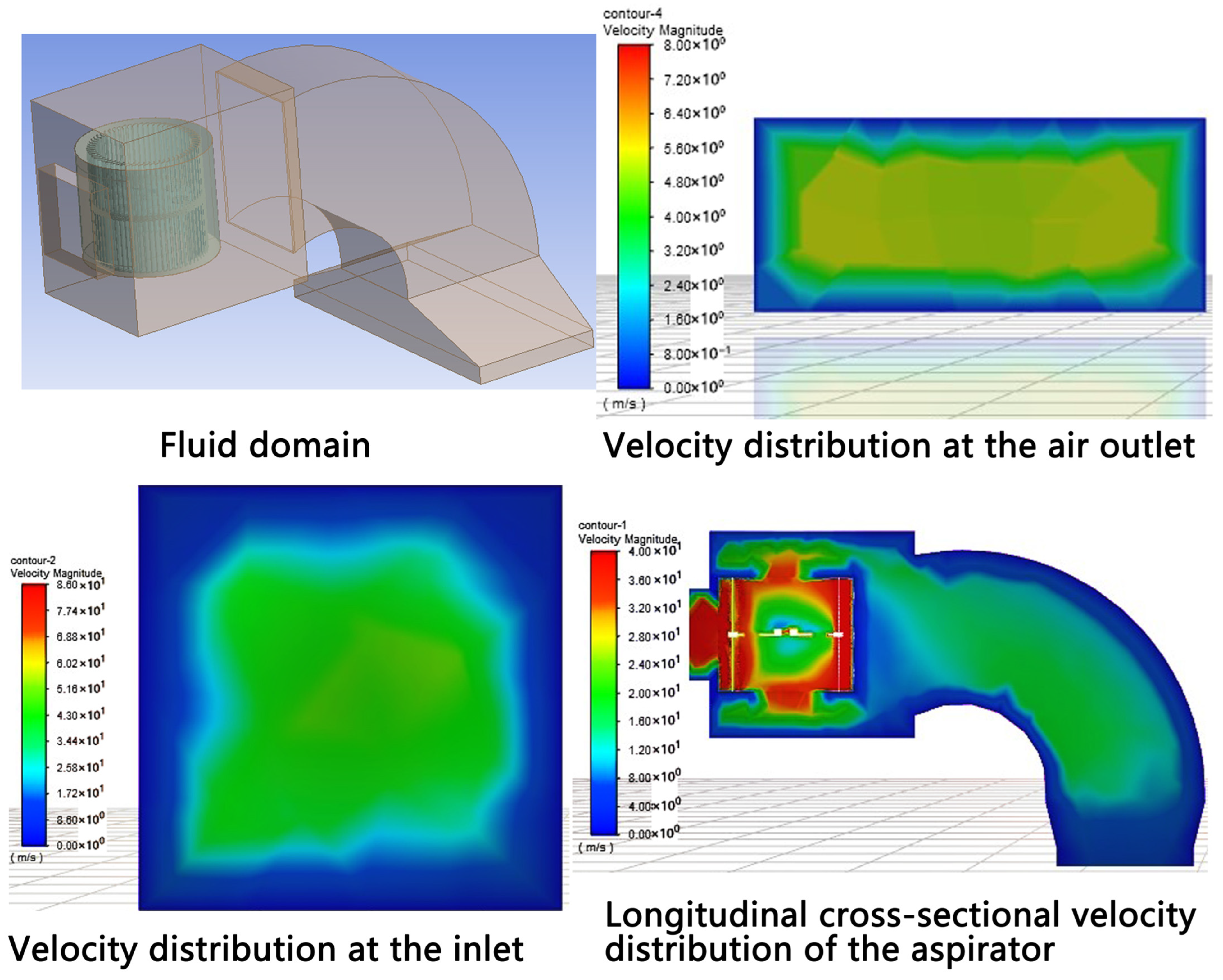
2.2. Analysis of Flow Velocity Distribution Inside the Suction Device

The preliminary design of the extraction unit includes components, such as motors and mounting plates, which have a minimal impact on the flow field and prevent a smooth simulation analysis. In order to improve the efficiency and accuracy of the simulation, the suction device shell was removed for fluid domain extraction during the CFD simulation, facilitating the observation of the internal flow field. During the analysis, the fan rotating area was defined as the region containing the stator to simulate the fan’s rotating state. Due to the fine structure of the stator, the grid was finely subdivided near the fan area, while areas without fine structure allowed for a larger grid size. The final grid had 401,974 cells.
For boundary conditions, the inlet was set as a velocity inlet with an initial velocity range of 2–5 m · s 1 . The outlet was set as a pressure outlet, and the stator area was assigned an initial rotational speed of 1000 rpm. Simulation results, including velocity contour maps, were used to analyze the flow field distribution and velocity comparisons at the suction device inlet and outlet. As shown in Figure 3, at a stator speed of 1000 rpm, the outlet velocity is approximately 18 m · s 1 , while the inlet wind velocity is about 5 m · s 1 . This inlet velocity is sufficient to suspend and unload the residual film from the elastic teeth, while the higher outlet wind speed aids in transporting the film from the air suction device to the collection system.
The simulation results confirm that the designed air suction device is effective for unloading and transporting the residual film. To account for the distance between the air inlet and the elastic teeth, an additional 50 mm wind field was added at the air inlet to assess wind velocity changes between the elastic teeth and the actual inlet. As shown in Figure 3, the velocity contour map indicates no significant change in wind velocity or uniformity within 50 mm of the air inlet, meeting the requirements for composite residual film discharge and film impurity separation.

2.3. Measurement and Calibration of Intrinsic Parameters of the Residual Film and Soil

Soil and film samples were collected from the 0–150 mm depth layer in the Tacheng region of Xinjiang using a five-point sampling method (Figure 4). After obtaining the soil, the soil moisture content was measured, and the resulting soil moisture content was 9% (Figure 4d). Soil granularity was also measured, and the particle diameters were concentrated in the range of 0.5–1 mm (>70%, Figure 4c). The average density of the soil was tested and calculated to be 1.61 × 10 3   k g · m 3 (Figure 4). The Poisson’s ratio, shear modulus of the soil, and inherent parameters of the elastic tooth (65 Mn) were obtained from reference sources (0.36, 1 × 10 6 ) [25,29]. The soil’s angle of repose was measured using the funnel method [25], with the self-made testing device consisting of an iron-framed table, a funnel, and an instrument for measuring the angle of repose (Figure 4). In the experiment, 2 kg of soil was loaded into the funnel and allowed to fall under gravity until a stable heap was formed. This procedure was repeated five times, measuring the angle of repose in four directions. The average value of these measurements (43.6°) was taken as the final value for the angle of repose of the soil. The residual film density was determined to be 915 k g · m 3 [30]. The Poisson’s ratio of residual film is 0.21, and the shear modulus (G) is 1.12 × 10 6 [25,29,31].

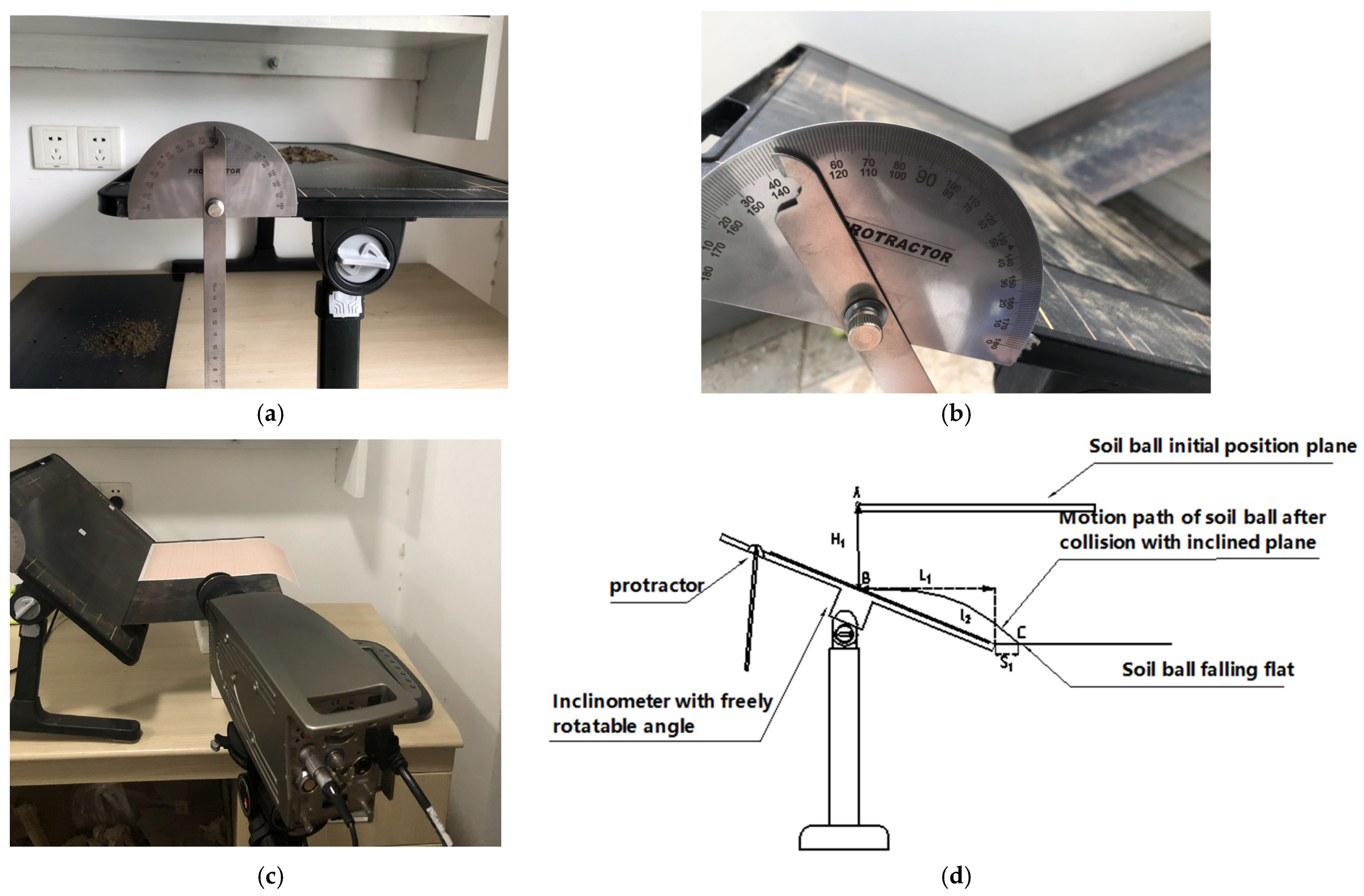
2.4. Contact Parameters

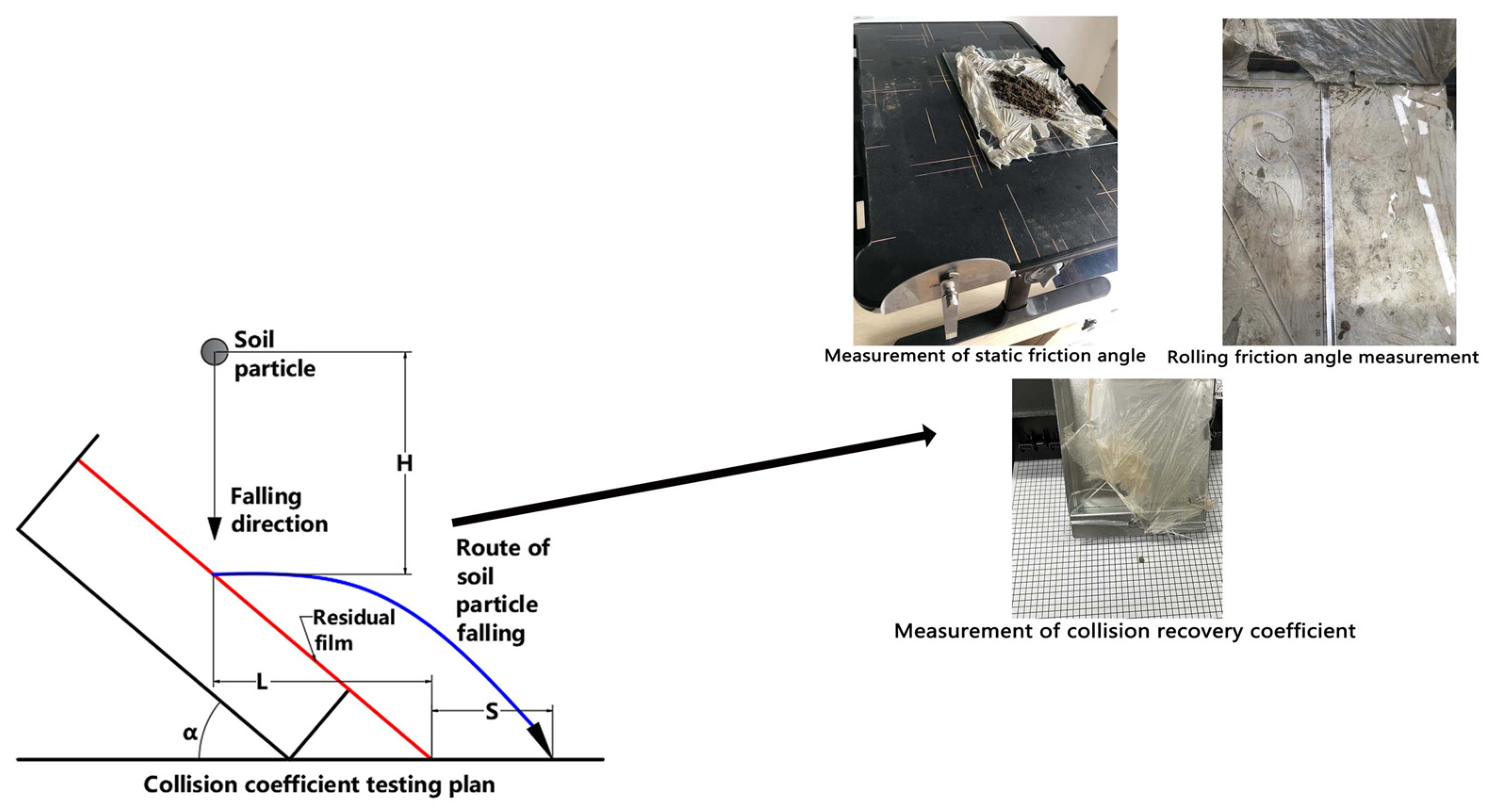
2.4.1. Contact Parameters of Soil–Elastic Tooth (65 Mn)

As shown in Figure 5, the static friction coefficient was measured using a homemade inclinometer equipped with an angle measuring device, with 65 Mn steel as the surface material of the inclinometer. The static friction coefficient of the soil, under certain moisture conditions, was determined using the slip method. A specified mass of soil was placed on top of the horizontally stationary inclinometer, and the inclinometer was slowly rotated around the horizontal axis until the soil particles began to slip off the incline. The angle between the inclined plane and the horizontal plane at this point was recorded as the static friction angle θ (26.5°). The static friction coefficient (μ) was calculated as 0.50 using Equation (11).
Additionally, as shown in Figure 5, measurements were taken with the 65 Mn steel inclinometer using the incline method, where soil balls were allowed to roll freely down the steel plate under specific soil moisture conditions. The angle of the inclined plane (θ) was set to 45°, and the straight-line distance from the sliding point to the horizontal plane (L) was 100 mm. The rolling friction coefficient was calculated to be 0.31 according to Equation (12) (where H = 70.7 mm and the average value of S was 158 mm).
The collision recovery coefficient was measured using the collision method, as shown in Figure 5. H 1 = 200 mm, S 2 = 170 mm, and the inclination angle of the plane was 45°. The inclined plane collision test was repeated ten times, with S 1 being measured in each trial. The average value of S 1 (9.8 mm) was taken as the final measurement. The collision process was captured using a high-speed camera (The maximum frame rate is 10,000 fps). From Equation (13), the contact time t 1 was calculated to be 0.2 s. Using Equation (14), the rebound velocity V B was determined to be 1.96 m · s 1 . The average time for particles to pass through the B–C region, t 2 , was calculated to be 0.16 s. From Equations (15) and (16), the rebound velocities in the y-direction ( V B y ) and x-direction ( V B X ) were calculated to be 0.01 m · s 1 and 0.84 m · s 1 , respectively, with the total rebound velocity ( V B ) being 0.84 m · s 1 . Therefore, the collision recovery coefficient for the soil–elastic tooth (65 Mn) was determined to be 0.43 (with an average value of S 1 = 9.8 mm and time t 2 = 0.16 s).
μ 1 = t a n θ
μ 1 = H ( L c o s θ 1 + S )
H 1 = 1 2 g t 1 2
V B = g t 1
V B X = L + S 1 t 2
S 2 sin 45 ° = V B y t 2 + 1 2 g t 2 2
where μ 1 is the static friction coefficient; θ is the static friction angle, °; Where, μ 1 is the rolling friction coefficient; H is the height before sliding, mm; L is the distance of rolling on the inclined plane, mm; S is the distance of rolling on the horizontal plane, mm; H 1 is the distance of the falling point from the collision point in the vertical direction, m; g is the acceleration of gravity, m · s 2 ; t 1 is the time of particle move from the falling point to the collision point, s ; V B is the velocity of the soil particles at the collision point, m · s 1 , S 2 is the distance from the collision point to the horizontal plane, m; V B y is the velocity of the soil particles in the vertical direction after the collision, m · s 1 ; V B X is the velocity of soil particles in a horizontal direction after the collision, m · s 1 ; S 1 is the distance of soil particles moving outside the inclined plane after the collision, m; t 2 is the time elapsed from collision to landing, s; L is the distance from collision point to horizontal plane, m.

2.4.2. Contact Parameters of Soil–Residual Film

(1)
Static friction coefficient of soil–residual film
As shown in Figure 6, the residual film was placed on a smooth glass plate, which served as the bottom surface. This setup ensured that the soil surface had the physical properties of the residual film, allowing the static coefficient of friction between the soil and the residual film to be measured using the slip method. The measurement was repeated five times, and the average value was taken as the static friction angle of the soil–residual film, which was found to be 28.8°. The static friction coefficient was then calculated using Equation (11), resulting in μ 1 = 0.55 .
(2)
Dynamic friction coefficient of soil–residual film
The residual film was placed on a smooth glass plate and used as a flat surface to measure the coefficient of static friction between the soil and the residual film using the slip method. The dynamic friction slope was set to 45°, with the length of the slope measuring 140 mm. According to Equation (12), the dynamic friction coefficient of the soil–residual film was calculated to be μ 2 = 0.46 (with H = 100 mm, L = 140 mm, θ 2 = 45°, S = 120 mm).
As shown in Figure 6, the collision recovery coefficient of the soil–residual film was measured using the oblique collision method (refer to Figure 5 in Section 2.4.1). The residual film was dropped vertically from a height of 100 mm, allowing the soil particles to fall freely. The testing procedure followed the same method used for the soil–elastic tooth (65 Mn). The parameters were calculated using Equations (13)–(16), and the results were as follows: V B = 1.37   m · s 1 , V B y = 0.19   m · s 1 , V B X = 0.68   m · s 1 , and V B = 0.71   m · s 1 . The collision recovery coefficient was calculated to be 0.5 (with H 1 = 100   m m , S 2 = 140   m m , L = 140   m m , S 1 = 13   m m , and t 2 = 0.16   s ).

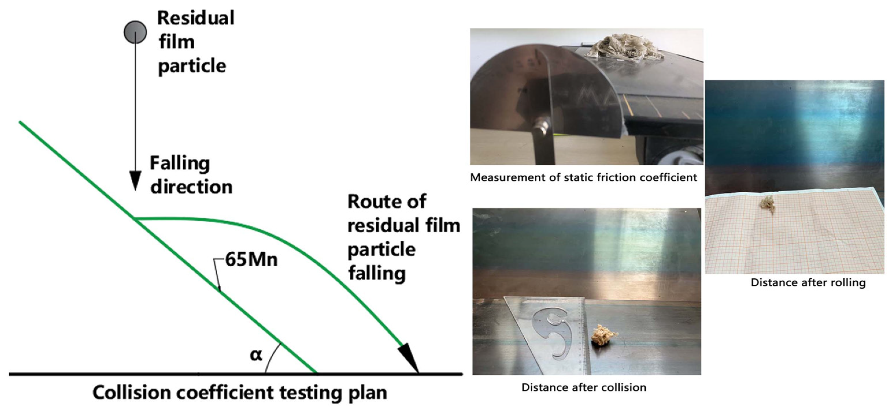
2.4.3. Contact Parameters of Residual Film–Elastic Tooth

As shown in Figure 7, 65 Mn steel was used as the inclined surface, and the inclined collision method was applied for the measurement. When the incline angle of the plane was set to 24°, the entire residual film slid down, indicating that the static friction angle between the residual film and elastic tooth was 24°. According to Equation (6), the static friction coefficient of the residual film–elastic tooth was calculated to be 0.45.
The sliding friction coefficient of the residual film elastic tooth was measured using the slip method, the procedure being based on the method of measuring the rolling friction coefficient of the soil residual film. Five different forms of residual film were tested. Using Equation (12), the rolling friction coefficient of the residual film–elastic tooth was calculated to be 0.40 (with L = 140 mm, H = 100 mm, S = 150 mm, and θ 2 = 45°).
Additionally, the steel plate was placed on the ground at a 45° incline, and residual films with different morphologies were allowed to fall freely from a specified height. The distance of ejection was recorded. The collision recovery coefficient was calculated using Equations (13)–(16), and the average value (0.5) of the collision recovery coefficient for the various forms of residual film was taken as the collision recovery coefficient of the residual film–elastic tooth. From Equations (13)–(16), the parameters were determined as follows: V B = 1.67   m · s 1 , V B y = 0.19   m · s 1 , V B X = 0.81   m · s 1 , and V B = 0.83   m · s 1 . Consequently, the collision recovery coefficient of the residual film–elastic tooth was found to be 0.5 (with H 1 = 150   m m , S 2 = 140   m m , L = 140   m m , S 1 = 30   m m , and t = 0.16   s ).

3. Results

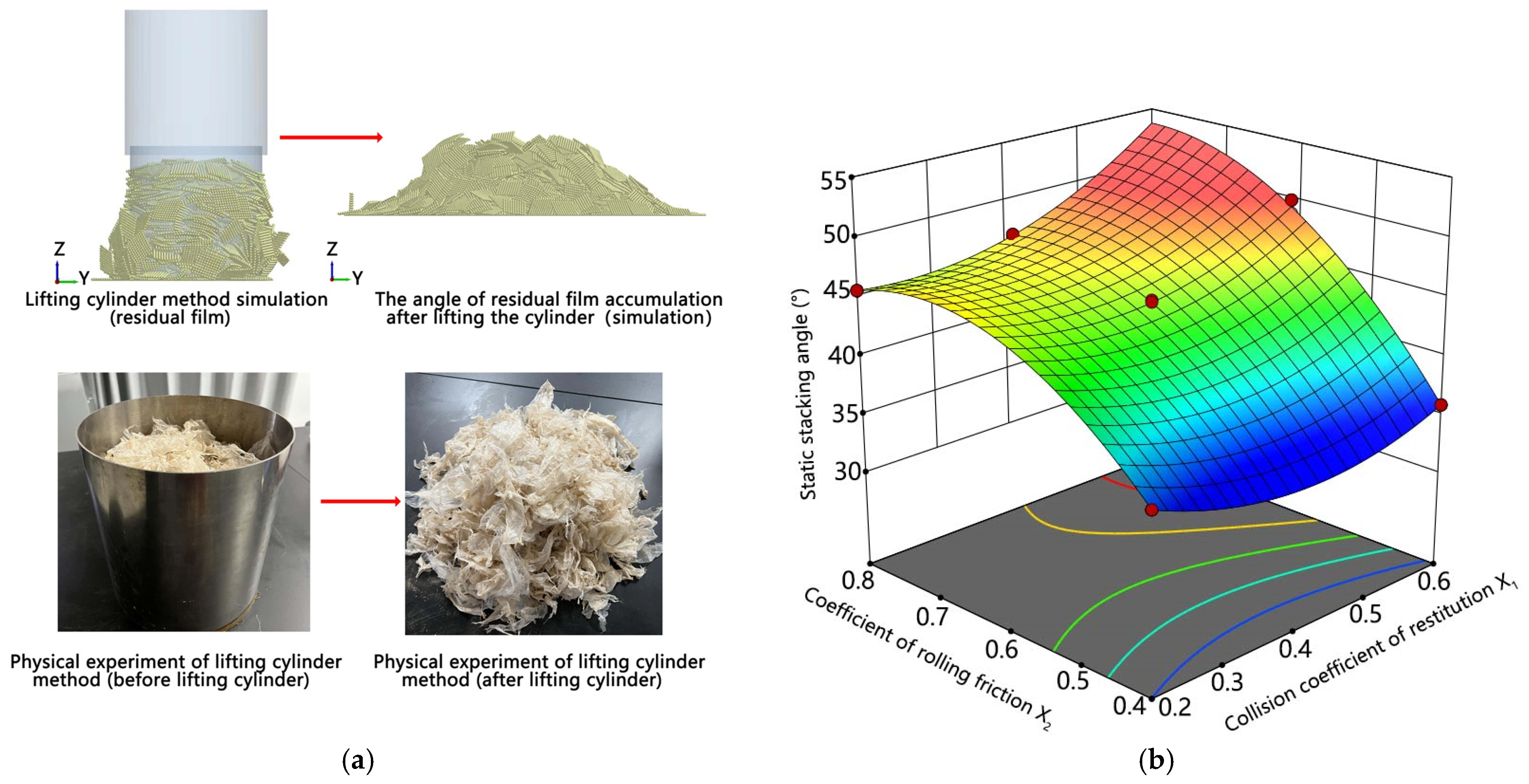
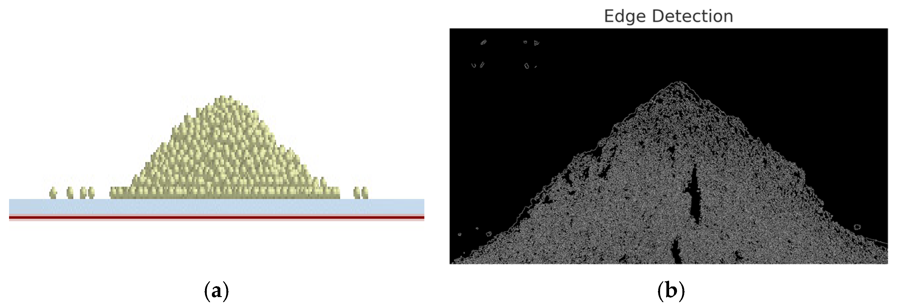
3.1. Residual Film—Residual Film Contact Parameters

The static friction angle between the residual film and itself was 27.5°, yielding a static friction coefficient of μ = tan(θ) = 0.52. As shown in Figure 8, the actual static friction coefficient was measured using the stacking angle method with the cylinder lifting technique. The average stacking angle from ten measurements was 43°, which was taken as the static friction angle for the residual film–residual film interaction.
The collision recovery and rolling friction coefficients for the residual film–residual film contact were calibrated using virtual parameters. Based on previous analysis, the collision recovery coefficient (A) was found to be between 0.2 and 0.6, and the rolling friction coefficient (B) was lower than the static friction coefficient, ranging from 0.4 to 0.8 (as shown in Table 1). To refine these parameters, experiments were conducted varying the stacking angle, with results summarized in Table 2 and Table 3.
From the optimized parameter analysis (Figure 8), the collision recovery coefficient was set at 0.4, and the rolling friction coefficient at 0.57. The simulation stacking angle matched the experimental value within an error of 1.6% (simulation: 43°, and experiment: 43.7°), confirming the reliability of the calibrated parameters. The DEM model of the residual film is shown in Figure 8b.

3.2. Soil–Soil Contact Parameters

Soil–soil contact parameters are difficult to measure directly, so their ranges were determined through a review of the existing literature. The parameter ranges are as follows: collision recovery coefficient (A): 0.2–0.6, static friction coefficient (B): 0.3–0.7, and rolling friction coefficient (C): 0.14–0.4 [15]. The actual values for these parameters were then determined through virtual simulation and parameter calibration (Figure 9).
A three-factor, three-level experiment was conducted to explore the parameter ranges, followed by a response surface analysis to identify the optimal values. The pre-experiment indicated that the stacking angle increased with the static friction coefficient, with the rolling friction coefficient peaking near 0.26 and the static friction coefficient reaching its peak at 0.6. However, the desired stacking angle was not achieved in the pre-experiment, indicating a need to increase the static friction coefficient. The refined parameter ranges after the three-level experiment are presented in Table 4.
Box–Behnken tests were then used to optimize the test factors—collision recovery coefficient, static friction coefficient, and rolling friction coefficient—with the stacking angle as the response variable. The optimized values from the Box–Behnken experiment, shown in Figure 10, were A = 0.52, B = 0.74, and C = 0.22. Statistical analysis (Table 5 and Table 6) confirmed that all three factors were significant, and the model could accurately predict more than 99% of scenarios.
The final stacking angle experiment, conducted with the optimized parameters, is shown in Figure 10. Error analysis between the simulation and experimental results revealed a 2.7% error (simulation: 43.6°, and experiment: 42.42°), which is within an acceptable range. This confirms that the calibrated soil–elastic tooth parameters are reliable and suitable for simulating the interaction between the touching parts and soil.

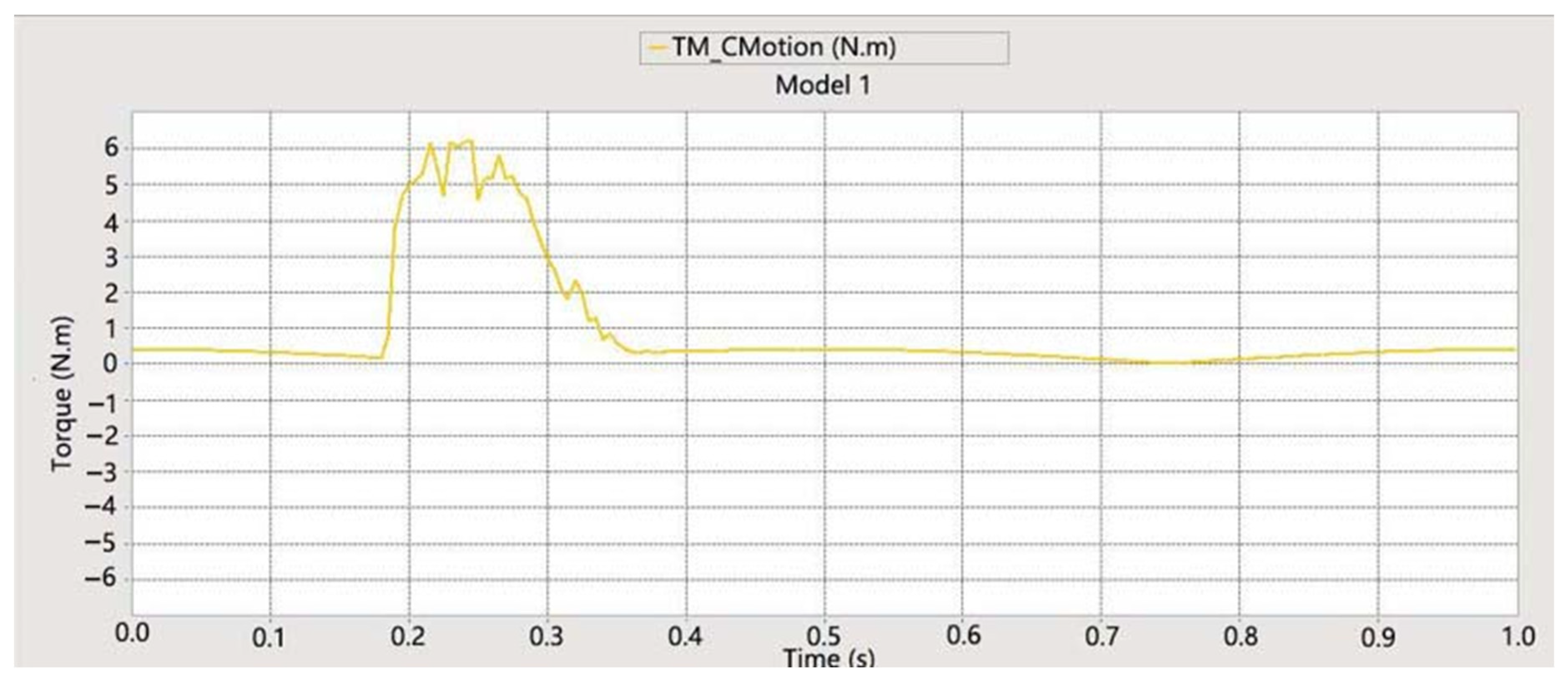
3.3. Analysis of the Torque Experienced During Film Picking with Elastic Teeth Based on DEM–MBD Coupling Simulation

DEM–MBD represents the coupled simulation of discrete element software and multi-body dynamics software, such as EDEM–RECURDYN coupled simulation, which can provide a more complex form of motion for simulating the interaction of mechanical components with soil and other particulate matter to more realistically simulate the motion characteristics of machines. In the EDEM–RECURDYN coupling simulation, the initial soil particle diameter was set to 2 mm. The experimental steps are as follows: first import the 3D model into the RECURDYN software, set up the motion, export the 3D model as a wall through the coupling interface for EDEM import, import the wall file into the EDEM software, set up a soil tank and a particle factory, and adjust the position relationship between the soil tank and the film picking teeth to the desired position. Open the EDEM coupling button and simulate in RECURDYN. EDEM simulates under the drive of RECURDYN. The torque magnitude of the elastic teeth during the film picking process is shown in Figure 11. The torque during the film picking process with the teeth is 5–6 N · m .

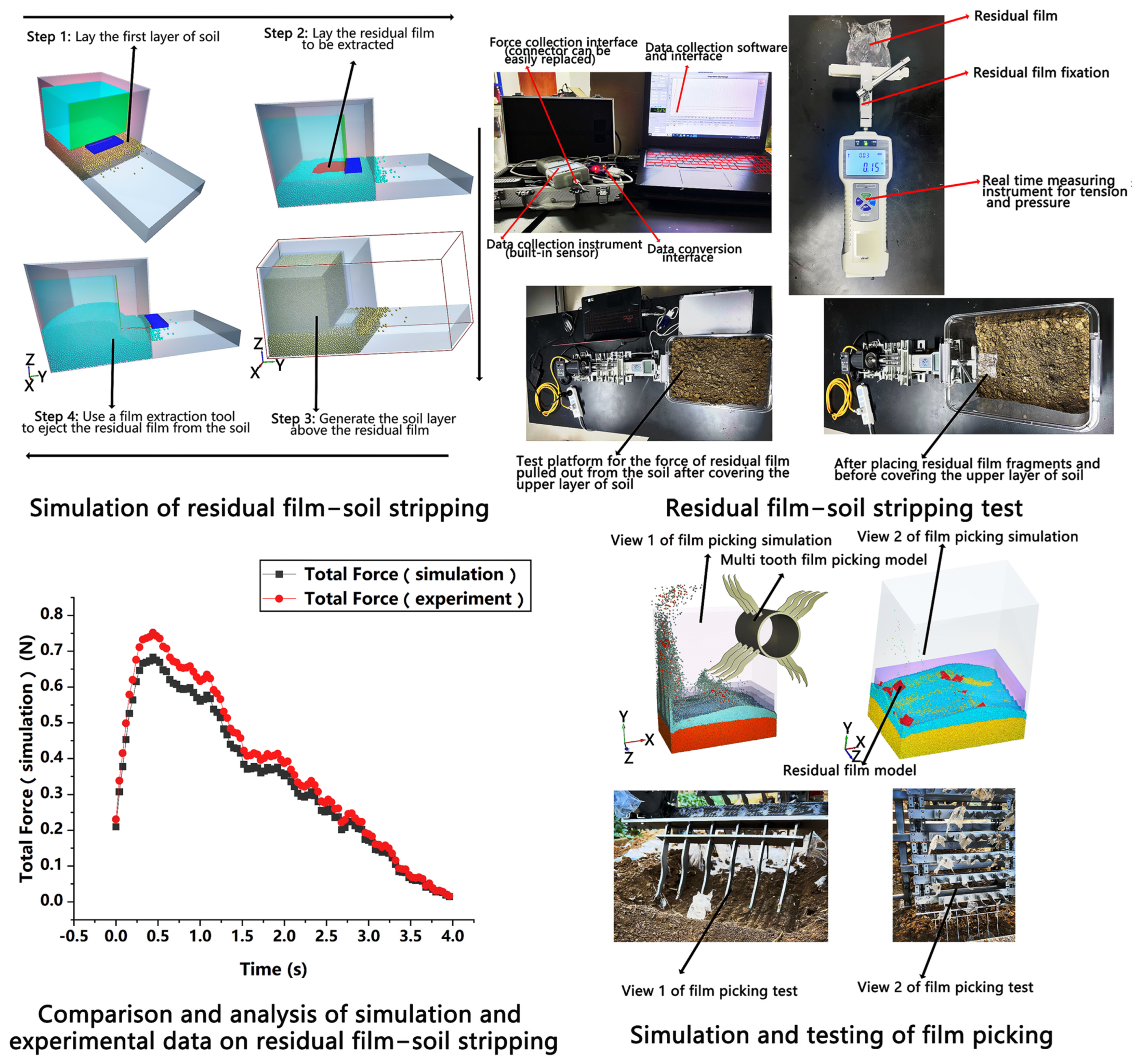
3.4. Analysis of the Peeling Characteristics and Mechanical Properties of Residual Film–Soil Based on DEM Simulation

As shown in Figure 12, modeling and force analysis were conducted for the residual film extraction process from the soil. During the simulation and testing, a section of the residual film was clamped and extracted from the soil at a velocity of 0.01 m∙s−1. The force at the contact area between the fixture and the residual film was measured in the simulation. In the experiment, after installing the fixture, the force was reset to zero to ensure that the measured force reflected only the force acting on the residual film. Both the simulation and experiment were repeated five times, yielding 8.1% error between the results (simulation: 0.34 N, and experiment: 0.37 N).
As shown in Figure 12, a film-lifting simulation model was established using DEM–MBD and was used to predict the film-lifting rate. The film-picking rate from the simulation was validated through experimental testing. Both the simulation and experiment were repeated ten times, with an average error of 2% (simulation: 90%, and experiment: 92%). These results confirm the reliability of the calibrated DEM parameters and the established DEM model.

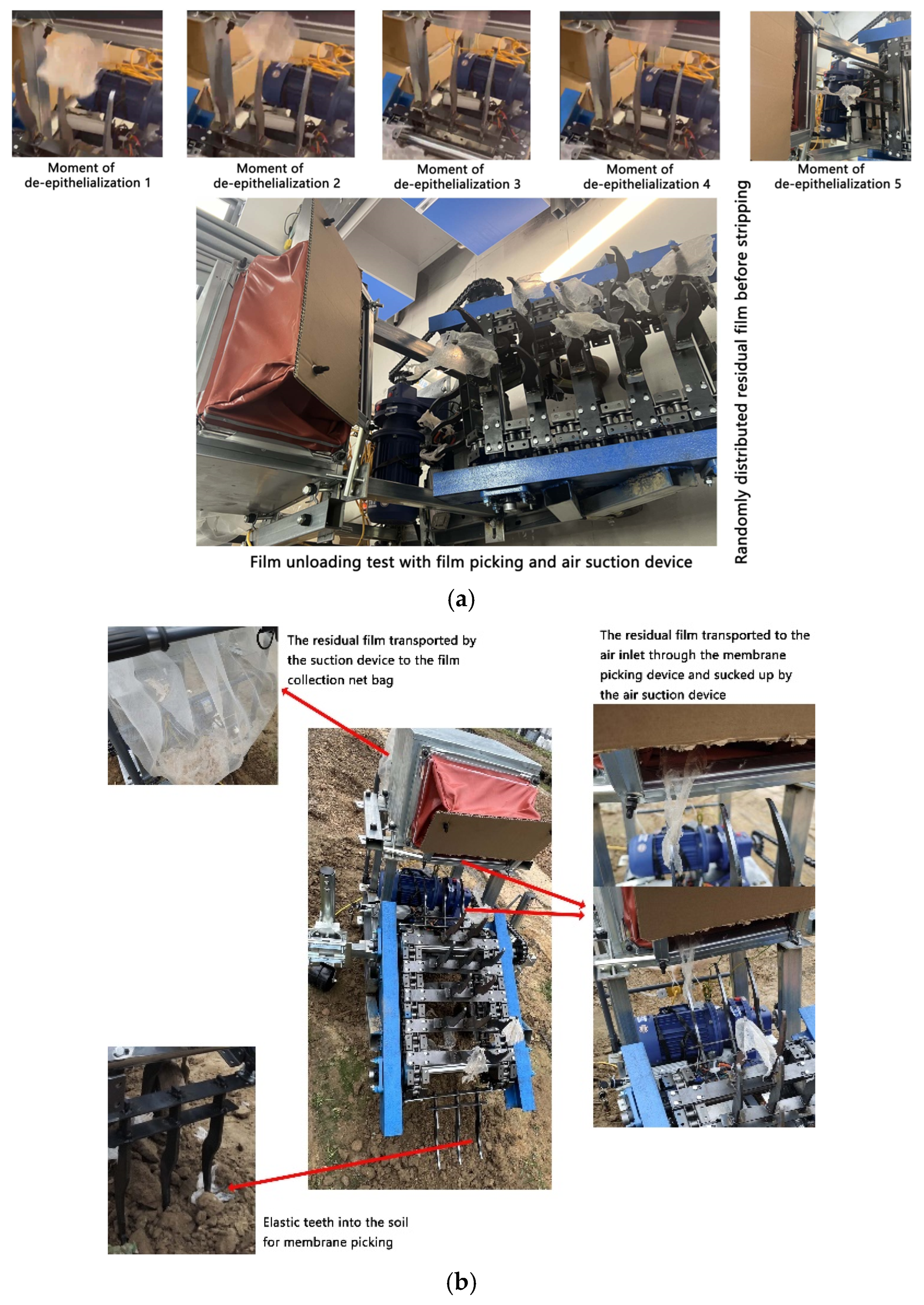
3.5. Field Film Harvesting Experiment Based on the Collaborative Operation of Membrane Picking Device and Air Suction Device

The residual films used in the film picking test were aged films obtained from cotton fields in Xinjiang after soil erosion. The working environment of this study is the recovery of tilled residue in a soft soil layer after deep loosening or rotary tilling. It is also possible that the loosening device could be combined with the device described in this study to form a combined machine in a later study. The recycling of residual film has only a loosening effect on the soil and does not produce any side effects. In addition, the soil structure of the cotton field will be more favorable to the water and air uptake capacity of the crop after the residual film has been recycled. In the field test, a plot with a width of 200 mm and a length of 500 mm was set up, and the rotational speed of the film picker was set to 100 rpm based on the forward velocity (1.38 m · s 1 ), and the wind speed of the inlet of the air suction unit (the wind speed of the suction port) was adjusted to 3 m · s 1 . This wind velocity was measured according to the characteristics of the residual film material to obtain the value, higher than the suspension velocity of the residual film, lower than the suspension velocity of the soil, so that the soil will not be sucked away by the air suction film unloading device, but fall back to the ground under the effect of gravity. The width of the inlet of the air suction unit in the tangential direction of the film picker was set to 50 mm. According to the residual film density obtained from the study, the residual film fragments were placed in the soil within a depth of 150 mm in the working area. After the preparation work was completed, the film harvesting test was carried out, and the film picking rate and film unloading rate were counted. The test procedure is shown in Figure 13. The film picking test and the air suction film unloading test were repeated 10 times, and the average values were taken as the final film picking and unloading rates. The results showed that the film picking rate was 88% and the film unloading rate was 89%, both of which met the usage requirements. It can be seen that the film picking device and air suction film unloading device designed in this study have good usability, and the film picking device and film unloading device work well together, which is suitable for the recycling of residual film in the range of 0–150 mm of the depth of the plow layer.

4. Discussion

Few studies have focused on calibrating the DEM parameters for the interaction between elastic teeth, soil, and residual film. As a result, it is challenging to predict the performance of the film-picking device in residual film recovery machines using the DEM method. The design of the elastic teeth significantly affects the recovery efficiency. This study calibrates the DEM parameters for the elastic tooth-soil-residual film system and establishes a DEM–MBD simulation model, laying the foundation for predicting the force between residual film and soil, as well as the residual film recovery rate. This research offers valuable insights into improving the recovery rate of residual film recycling machines, while reducing damage and power consumption of the elastic teeth, making it of great research value. In this study, after determining the minimum film leakage area, the film picking device was operated at the minimum rotational speed of 80 rpm and forward velocity of 1.38 m · s 1 , which ensured that a high recovery rate was achieved with less energy loss during the film picking process.
This paper focuses on parameter calibration for the elastic tooth–soil–residual film interactions, an area with limited research due to the flexible nature of crops and the need for studies on soil-touching components [32,33]. Several self-developed tools were used for calibrating the elastic tooth–soil–flexible body parameters, which have significant reference value for calibrating parameters in soil cultivation equipment and plant roots. For instance, Zhu et al. (2022) and Zhao et al. (2020) calibrated the parameters for soil–tire interaction and validated the simulation data by comparing the simulation and experimental pressure values, yielding an error of 3.4% [34,35]. Pasthy et al. (2024) calibrated soil–tiller interaction parameters and verified their reliability by comparing simulation and experimental force values between the tiller and soil [36]. The method of verifying parameter calibration by comparing simulation and experimental results is feasible.
Although the calibration of DEM parameters for flexible-body soil interaction has been applied, limited research exists on measuring the interaction forces between flexible bodies and soil through DEM methods. This research is both significant and challenging [37]. The reliability of the calibrated parameters was verified by comparing simulation and experimental force values during the extraction of residual film from soil. Calibrating DEM parameters for the tiller–soil–residual film system allows for simulating both the dynamic behavior of individual particles at the micro level and the bulk material behavior at the macro level, which is crucial for optimizing agricultural machinery performance [38].
The parameter calibration method presented in this paper systematically reviews existing calibration methods and applies them to the material parameters of the elastic tooth–soil–residual film system. To date, little research has focused on calibrating residual film parameters. The data obtained can be used for interaction analysis and parameter optimization of soil-touching components, offering valuable insights and references for calibrating flexible objects and multi-body contact parameters.

5. Conclusions

(1)
This paper calibrates the parameters for the elastic tooth–soil–residual film system. Intrinsic soil parameters, including Poisson’s ratio, density, shear modulus, stacking angle, and particle size distribution, were determined through experimental methods and a literature review. Contact parameters, such as the static friction coefficient, rolling friction coefficient, and collision recovery coefficient for soil–steel interactions, were measured using the slip method, inclined method, and inclined collision method. The soil–soil contact parameters—static friction coefficient, rolling friction coefficient, and collision recovery coefficient—were more difficult to obtain experimentally, so they were determined via virtual parameter calibration. The calibrated values for the soil–soil contact parameters were 0.74, 0.22, and 0.52, respectively, with a stacking angle error of 2.7% compared to experimental results. The residual film–residual film rolling friction coefficient and collision recovery coefficient were calibrated at 0.4 and 0.57, respectively, with a stacking angle error of 1.6%, which is within the acceptable range.
(2)
A DEM–MBD coupling simulation model of the elastic tooth–soil–residual film system was established to predict the force required to extract residual film from soil and the residual film recovery rate. Comparative analysis of simulation and experimental results for both force and recovery rate revealed an 8.1% error in the force measurement (simulation: 0.34 N, experiment: 0.37 N) and a 2% error in the recovery rate (simulation: 90%, experiment: 92%). This study provides valuable insights for the microscopic analysis of soil-touching components, soil–plant root interactions, and the optimization of agricultural machinery performance. This study can also provide a reference for the design of similar residual film recycling equipment.

Author Contributions

W.F.: methodology, data analysis, writing—original draft, review and editing. X.W.: supervision, funding acquisition, review and editing. D.H.: writing—review and editing. I.E.O.: writing—review and editing. All authors have read and agreed to the published version of the manuscript.

Funding

This study was supported by National Key R&D Program of China (No. 2022YFD2002403), Ministry of Industry and Information Technology’s Residual Film Recycling Machine Project (No. zk20230359), the Priority Academic Program Development of Jiangsu Higher Education Institutions (No. PAPD-2023-87), the 2023 Open Project of Key Laboratory of Modern Agricultural Equipment and Technology (Jiangsu University), Ministry of Education and High-tech Key Laboratory of Agricultural Equipment and Intelligence of Jiangsu Province (No. MAET202327).

Data Availability Statement

All data used in this manuscript are contained within the article.

Conflicts of Interest

The authors declare that they have no known competing financial interests or personal relationships that could have appeared to influence the work reported in this paper.

References

  1. Liang, R.; Zhu, Z.; Peng, C.; Bian, Z.; Yang, X.; Wang, H.; Wang, X.-X. Mulch film to plastic debris: A survey of agricultural soils of Hebei Province, North China. Sci. Total Environ. 2024, 918, 170509. [Google Scholar] [CrossRef] [PubMed]
  2. Wang, X.; Fang, W.; Han, D.; Chen, X. Review of the research on soil disturbance by tools. Appl. Sci. 2023, 13, 338. [Google Scholar] [CrossRef]
  3. Kim, Y.S.; Lee, S.D.; Baek, S.M.; Baek, S.Y.; Jeon, H.H.; Lee, J.H.; Siddique, A.A.; Kim, Y.J.; Kim, W.S.; Sim, T.; et al. Development of DEM-MBD coupling model for draft force prediction of agricultural tractor with plowing depth. Comput. Electron. Agric. 2022, 202, 107405. [Google Scholar] [CrossRef]
  4. Tamas, K.; Bernon, L. Role of particle shape and plant roots in the discrete element model of soil-sweep interaction. Biosyst. Eng. 2021, 211, 77–96. [Google Scholar] [CrossRef]
  5. Du, J.; Heng, Y.; Zheng, K.; Luo, C.; Zhu, Y.; Zhang, J.; Xia, J. Investigation of the burial and mixing performance of a rotary tiller using discrete element method. Soil Tillage Res. 2022, 220, 105349. [Google Scholar] [CrossRef]
  6. Li, C.; Yin, H.; Wu, C.; Zhang, Y.; Zhang, J.; Wu, Z.; Wang, W.; Jia, D.; Guan, S.; Ren, R. Calibration of the discrete element method and modeling of shortening experiments. Front. Earth Sci. 2021, 9, 636512. [Google Scholar] [CrossRef]
  7. Syed, Z.; Tekeste, M.; White, D. A coupled sliding and rolling friction model for DEM calibration. J. Terramechanics 2017, 72, 9–20. [Google Scholar] [CrossRef]
  8. Qu, T.; Feng, Y.; Zhao, T.; Wang, M. A hybrid calibration approach to Hertz-type contact parameters for discrete element models. Int. J. Numer. Anal. Methods Geomech. 2020, 44, 1281–1300. [Google Scholar] [CrossRef]
  9. Liang, Z.; Huang, Y.; Li, D.; Wada, M.E. Parameter determination of a viscoelastic-plastic contact model for potatoes during transient collisions. Biosyst. Eng. 2023, 234, 156–171. [Google Scholar] [CrossRef]
  10. Du, C.; Han, D.; Song, Z.; Chen, Y.; Chen, X.; Wang, X. Calibration of contact parameters for complex shaped fruits based on discrete element method: The case of pod pepper (Capsicum annuum). Biosyst. Eng. 2023, 226, 43–54. [Google Scholar] [CrossRef]
  11. Shi, Q.; Wang, B.; Mao, H.; Liu, Y. Calibration and measurement of micrometre-scale pollen particles for discrete element method parameters based on the Johnson-Kendal-Roberts model. Biosyst. Eng. 2024, 237, 83–91. [Google Scholar] [CrossRef]
  12. Cheng, J.; Zheng, K.; Xia, J.; Liu, G.; Jiang, L.; Li, D. Analysis of adhesion between wet clay soil and rotary tillage part in paddy field based on discrete element method. Processes 2021, 9, 845. [Google Scholar] [CrossRef]
  13. Yang, Y.; Wen, B.; Ding, L.; Li, L.; Chen, X.; Li, J. Soil particle modeling and parameter calibration for use with discrete element method. Trans. ASABE 2021, 64, 2011–2023. [Google Scholar] [CrossRef]
  14. Zhao, L.; Zhou, H.; Xu, L.; Song, S.; Zhang, C.; Yu, Q. Parameter calibration of coconut bran substrate simulation model based on discrete element and response surface methodology. Powder Technol. 2022, 395, 183–194. [Google Scholar] [CrossRef]
  15. Dai, Z.; Wu, M.; Fang, Z.; Qu, Y. Calibration and verification test of lily bulb simulation parameters based on discrete element method. Appl. Sci. 2021, 11, 10749. [Google Scholar] [CrossRef]
  16. Yuan, H.; Liang, S.; Wang, J.; Lu, Y. Numerical Simulation and Analysis of Vibrating Rice Filling Based on EDEM Software. Agriculture 2022, 12, 2013. [Google Scholar] [CrossRef]
  17. Fang, W.; Wang, X.; Han, D.; Chen, X. Review of Material Parameter Calibration Method. Agriculture 2022, 12, 706. [Google Scholar] [CrossRef]
  18. Zhang, Y.; Zhao, Z.; Li, X.; Xue, Z.; Jin, M.; Deng, B. Near-Infrared-Based Measurement Method of Mass Flow Rate in Grain Vibration Feeding System. Agriculture 2024, 14, 1476. [Google Scholar] [CrossRef]
  19. Ma, Z.; Wu, Z.; Li, Y.; Song, Z.; Yu, J.; Li, Y.; Xu, L. Study of the grain particle-conveying performance of a bionic non-smooth-structure screw conveyor. Biosyst. Eng. 2024, 238, 94–104. [Google Scholar] [CrossRef]
  20. Mudarisov, S.; Farkhutdinov, I.; Khamaletdinov, R.; Khasanov, E.; Mukhametdinov, A. Evaluation of the significance of the contact model particle parameters in the modelling of wet soils by the discrete element method. Soil Tillage Res. 2022, 215, 105228. [Google Scholar] [CrossRef]
  21. Wang, X.; Li, J. Simulation of triaxial response of granular materials by modified DEM. Sci. China-Phys. Mech. Astron. 2014, 57, 2297–2308. [Google Scholar] [CrossRef]
  22. Schramm, M.W.; Tekeste, M.Z.; Steward, B.L. Simulation of uniaxial compression for flexible fibers of wheat straw using the discrete element method. Trans. ASABE 2021, 64, 2025–2034. [Google Scholar] [CrossRef]
  23. Xia, R.; Li, B.; Wang, X.; Li, T.; Yang, Z. Measurement and calibration of the discrete element parameters of wet bulk coal. Measurement 2019, 142, 84–95. [Google Scholar] [CrossRef]
  24. Mak, J.; Chen, Y.; Sadek, M.A. Determining parameters of a discrete element model for soil-tool interaction. Soil Tillage Res. 2012, 118, 117–122. [Google Scholar] [CrossRef]
  25. Wang, X.; Gao, P.; Yue, B.; Shen, H.; Fu, Z.; Zheng, Z.; Huang, Y. Optimization of installation parameters of subsoiler’ wing using the discrete element method. Comput. Electron. Agric. 2019, 162, 523–530. [Google Scholar] [CrossRef]
  26. Kim, Y.S.; Siddique, M.A.A.; Kim, W.S.; Kim, Y.J.; Lee, S.D.; Lee, D.K.; Hwang, S.J.; Nam, J.S.; Park, S.U.; Lim, R.G. DEM simulation for draft force prediction of moldboard plow according to the tillage depth in cohesive soil. Comput. Electron. Agric. 2021, 189, 106368. [Google Scholar] [CrossRef]
  27. Kesner, A.; Choteborsky, R.; Linda, M.; Hromasova, M.; Katinas, E.; Sutanto, H. Stress distribution on a soil tillage machine frame segment with a chisel shank simulated using discrete element and finite element methods and validate by experiment. Biosyst. Eng. 2021, 209, 125–138. [Google Scholar] [CrossRef]
  28. Zhang, L.; Zhai, Y.; Wu, C.; Huang, S.; Zhang, Z. Modeling the interaction between a new four-bar subsoiling mechanism and red soil using the improved differential evolution algorithm and DEM. Comput. Electron. Agric. 2023, 208, 107783. [Google Scholar] [CrossRef]
  29. Guo, J.; Zhang, Q.; Muhammad, S.M.; Ji, C.; Zhao, Z. Design and experiment of bionic mole’s toe arrangement serrated blade for soil-rototilling and straw-shattering. Trans. Chin. Soc. Agric. Eng. (Trans. CSAE) 2017, 33, 43–50. [Google Scholar] [CrossRef]
  30. Hu, G.; Quan, L.; Zou, Y.; Shen, H. Establishment and simulation test of membrane-soil separation model for mechanical recycling of agricultural residual film. J. Hunan Agric. Univ. 2021, 47. [Google Scholar] [CrossRef]
  31. Fang, W.; Wang, X.; Han, D.; Zang, N.; Xue, G.; Israel, E.O. Parameter Optimization and Disturbance Analysis of the Film Picking Device of the Chain-Type Plough Layer Residual Film Recovery Machine Based on DEM-MBD Coupling. Comput. Electron. Agric. 2024, 222, 109041. [Google Scholar] [CrossRef]
  32. Zhao, J.; Yu, J.; Sun, K.; Wang, Y.; Liang, L.; Sun, Y.; Zhou, L.; Yu, Y. A discrete element method model and experimental verification for wheat root systems. Biosyst. Eng. 2024, 244, 146–165. [Google Scholar] [CrossRef]
  33. Yang, Q.; Shi, L.; Shi, A.; He, M.; Zhao, X.; Zhang, L.; Addy, M. Determination of key soil characteristic parameters using angle of repose and direct shear stress test. Int. J. Agric. Biol. Eng. 2023, 16, 143–150. [Google Scholar] [CrossRef]
  34. Zhu, J.; Zou, M.; Liu, Y.; Gao, K.; Su, B.; Qi, Y. Measurement and calibration of DEM parameters of lunar soil simulant. Acta Astronaut. 2022, 191, 169–177. [Google Scholar] [CrossRef]
  35. Zhao, Z.; Li, H.; Liu, J.; Yang, S.X. Control method of seedbed compactness based on fragment soil compaction dynamic characteristics. Soil Tillage Res. 2020, 198, 104551. [Google Scholar] [CrossRef]
  36. Pasthy, L.; Farkasm, Z.J.; Haba, T.; Tamas, K. Development of a multi-way coupled discrete-finite element method simulation procedure for modelling soil-passive vibration tool interaction. Comput. Electron. Agric. 2024, 216, 108459. [Google Scholar] [CrossRef]
  37. Zhang, S.; Yang, F.; Dong, J.; Chen, X.; Liu, Y.; Mi, G.; Wang, T.; Jia, X.; Huang, Y.; Wang, X. Calibration of Discrete Element Parameters of Maize Root and Its Mixture with Soil. Processes 2022, 10, 2433. [Google Scholar] [CrossRef]
  38. Walunj, A.; Chen, Y.; Tian, Y.; Zeng, Z. Modeling Soil-Plant-Machine Dynamics Using Discrete Element Method: A Review. Agronomy 2023, 13, 1260. [Google Scholar] [CrossRef]
Figure 1. The structure of the chain–tooth air suction tillage residual film recovery machine. (a) Test bench design drawing; (b) Description of key dimensions.
Agronomy 15 00955 g001
Figure 2. Analysis of the forward traction of elastic teeth.
Agronomy 15 00955 g002
Figure 3. Flow field analysis and simulation results of the first-stage intake device in the fluid domain.
Agronomy 15 00955 g003
Figure 4. Soil intrinsic parameter acquisition. (a) Soil density measurement; (b) Soil angle of repose measurements; (c) Soil granularity measurements; (d) Soil moisture content measurements; (e) Acquisition of old residual films in cotton field tillage.
Agronomy 15 00955 g004
Figure 5. Experiment for static friction coefficient calculation and the collision recovery coefficient. (a) Experiment for static friction coefficient calculation; (b) Experiment for coefficient of rolling friction; (c) Experiment for the collision recovery coefficient; (d) Parameter description of inclinometer.
Agronomy 15 00955 g005
Figure 6. Measurement of contact parameters between soil and residual film.
Agronomy 15 00955 g006
Figure 7. Measurement of the collision recovery coefficient and rolling friction coefficient between the residual film and elastic tooth.
Agronomy 15 00955 g007
Figure 8. (a) Cylinder lifting method for measuring residual film-to-residual film contact parameters; (b) Optimization results of residual film-to-residual film parameters and the residual film model.
Agronomy 15 00955 g008
Figure 9. Comparison of simulation and experimental results for stacking angle. (a) Simulation of the stacking angle measurement process (Funnel was hidden); (b) Test stacking angle measurement procedure.
Agronomy 15 00955 g009
Figure 10. Results of the Box–Behnken experiment for soil particle parameter calibration: (a) Response surface with X 1 and X 2 as influencing factors; (b) Response surface with X 1 and X 3 as influencing factors; (c) Response surface with X 2 and X 3 as influencing factors.
Agronomy 15 00955 g010
Figure 11. The amount of torque applied to the teeth during the process of picking up the film with the teeth.
Agronomy 15 00955 g011
Figure 12. Analysis of residual film–soil stripping results.
Agronomy 15 00955 g012
Figure 13. Experimental study on the film release performance of a single-tooth air suction device under different operating parameters. (a) Membrane unloading test; (b) Membrane picking test.
Agronomy 15 00955 g013
Table 1. Test factor table for residual film-to-residual film interaction.
Coefficient of Recovery RestitutionCoefficient of Rolling Friction
0.20.4
0.40.6
0.60.8
Table 2. Residual film-to-residual film contact parameter calibration test data sheet.
No.Collision Coefficient of
Restitution X1
Coefficient of Rolling
Friction X2
Static Stacking Angle Y1
10.20.436.81
20.20.845.65
30.40.846.71
40.40.644.68
50.40.846.88
60.40.644.49
70.40.644.53
80.40.644.85
90.60.435.88
100.60.648.73
110.60.649.90
Table 3. Analysis of variance for the regression equation.
SourceStatic Stacking Angle Y1
Sum of SquaresDegree of FreedomFSignificant Level
Model191.73540.55<0.0001 **
A10.44129.570.0004 *
B45.641155.90<0.0001 **
AB10.731108.660.0004 **
A 2 15.05124.070.0002
B 2 36.671 <0.0001 **
Pure Error0.77925
Cor Total192.5110
Note: ** means extremely significant; * means significant.
Table 4. Table of experimental factors and value ranges for soil–soil contact parameters.
LevelsCollision Recovery CoefficientCoefficient of Static FrictionCoefficient of Rolling Friction
−10.400.700.20
00.500.750.26
10.600.800.32
Table 5. Soil–soil contact parameter calibration test data sheet.
RunA-Collision Recovery CoefficientB-Coefficient of Static FrictionC-Coefficient of Rolling Friction Y 1 -Static Stacking Angle/°
1−1−1043.13
21−1042.42
3−11041.84
411039.98
5−10−138.55
610−141.13
7−10143.71
810144.57
90−1−143.85
1001−138.12
110−1140.27
1201142.71
1300044.71
1400044.71
1500044.71
1600044.71
1700044.71
Table 6. Variance analysis of the regression equation.
SourceStatic Stacking Angle Y1
Sum of SquaresDegree of FreedomFSignificant Level
Model62.39951.31<0.0001 **
A3.29124.350.0017 *
B45.031333.29<0.0001 **
C7.24153.580.0002 *
AB1.1618.550.0222
AC0.129610.95920.3600
BC0.342212.530.1555
A24.51133.420.0007
B20.349212.580.1519
C20.083110.61520.4586
Residual0.94577
Lack of Fit0.550231.850.2779
Pure Error0.39554
Cor Total63.3416
Note: ** means extremely significant; * means significant.
Disclaimer/Publisher’s Note: The statements, opinions and data contained in all publications are solely those of the individual author(s) and contributor(s) and not of MDPI and/or the editor(s). MDPI and/or the editor(s) disclaim responsibility for any injury to people or property resulting from any ideas, methods, instructions or products referred to in the content.

