Article

Effect of the Installation Angle of Nozzle on the Atomizing Performance of Air-Assisted Spraying Dust Suppression Device

1
School of Foreign Studies, Hunan University of Science & Technology, Xiangtan 411201, China
2
School of Resource, Environment & Safety Engineering, Hunan University of Science & Technology, Xiangtan 411201, China
*
Author to whom correspondence should be addressed.
Atmosphere 2022, 13(4), 520; https://doi.org/10.3390/atmos13040520
Submission received: 7 January 2022 / Revised: 26 February 2022 / Accepted: 17 March 2022 / Published: 24 March 2022

Abstract

:
Investigation of the JJPW-G100 air-assisted spraying dust suppression device was performed to obtain the reasonable installation angle of the nozzle in the air-assisted spraying dust suppression device. First, an equal-scale physical model was established, and then the effect of the installation angle of the nozzle on the atomizing performance of the air-assisted spraying dust suppression device was investigated in-depth via numerical simulation. Results showed that the installation angle of the nozzle imposed no significant effect on the spraying range of the air-assisted spraying dust suppression device, while the initial falling range in the spray field increased with the increasing installation angle. At the installation angle of over 45°, the loss of droplets at the outlet of the air cylinder disappeared. Mean droplet size of the spraying dust suppression device increased with the increasing installation angle, which first increased and then dropped with the increasing spraying range. The optimal installation angle of the nozzle was determined as 45°, under which the loss of droplets at the outlet of the air cylinder in the air-assisted spraying dust suppression device can be effectively prevented, while the dust suppression device can maintain a small droplet size and large falling range.

1. Introduction

With rapid development in mining, smelting, and machinery industries, the operating efficiency can be significantly enhanced; however, dust concentration has been increasing drastically, bringing serious pollution to the environment [1,2,3,4,5,6,7,8]. Spraying dust suppression is the main method for dust prevention and control [9,10,11,12,13,14,15,16]. Currently, a novel spraying dust suppression equipment, i.e., air-assisted spraying dust suppression device, has already been put into operation. The operating principle of the device is that using the spraying gravity dust suppression technique, water can be atomized into fine droplets with similar sizes to dust particles under high pressure, and then under the action of the fan, water mist can be ejected above the dust source or the surroundings for spraying coverage. Compared with other spraying devices such as sprinklers and spray guns, the air-assisted spraying dust suppression device shows a series of advantages mainly including low water consumption and a large coverage range [17,18,19].
Many scholars have conducted a great deal of research on the novel spraying dust suppression device. Aiming at further improving the structure and enhancing spraying dust suppression performance, Wang Lilin et al. designed a new transmission scheme to address the frequent appearance of the torsion of power transfer shaft in the fan driver of the air-assisted spraying dust suppression device; by replacing the coupling in a traditional fan with a one-way overrunning clutch, the torsion of power output transfer of the fan blades can be thoroughly solved, thereby enhancing the service life of the fan [20]. Zhou Hongwei et al. focused on the short spraying distance and poor atomizing performance of the air-assisted spraying dust suppression device, and made the improvements in the aspects of the pump selection, pipe design, and nozzle ring design; after experimental validation, they designed a whole new pipe system for the fog gun to enhance the atomizing performance [21]. In order to solve the mechanical wear induced by the imbalance of fan blades in the air-assisted spraying dust suppression device, Chai Shujie et al. designed a hard support dynamic balancing machine and experimentally validated that the design can effectively prevent mechanical wear [22]. Wang Yongzhen et al. designed a high-efficiency dust suppression fog gun system for the excavation face in coal mines, which mainly consisted of the focus-type source-control dust suppression fog gun, the divergence-type separation dust suppression fog gun, and water-jet imbibition device; based on the application results in the fully-mechanized excavation face in the No. 480 material lane owned by Zhangcun Coal Mine, the dust suppression efficiency can be enhanced by 30% compared with that using original dust suppression system [23].
Most of the existing studies regarding air-assisted spraying dust suppression devices have focused on the improvement of inner structure, while the effect of the installation angle of the nozzle on the spraying ring on the atomizing performance of the air-assisted spraying dust suppression device has been poorly investigated [24,25,26,27,28,29]. Therefore, based on previous research results, this study focused on the JJPW-G100 air-assisted spraying dust suppression device (Hunan Jiujiu Environmental Protection Intelligent Co., Ltd., Changsha, China). and performed a numerical simulation to explore the effect of the installation angle of the nozzle on the atomizing performance. The present research results are expected to provide theoretical support for the optimal design of the air-assisted spraying dust suppression device.

2. Establishment of the Physical Model and Mathematical Model
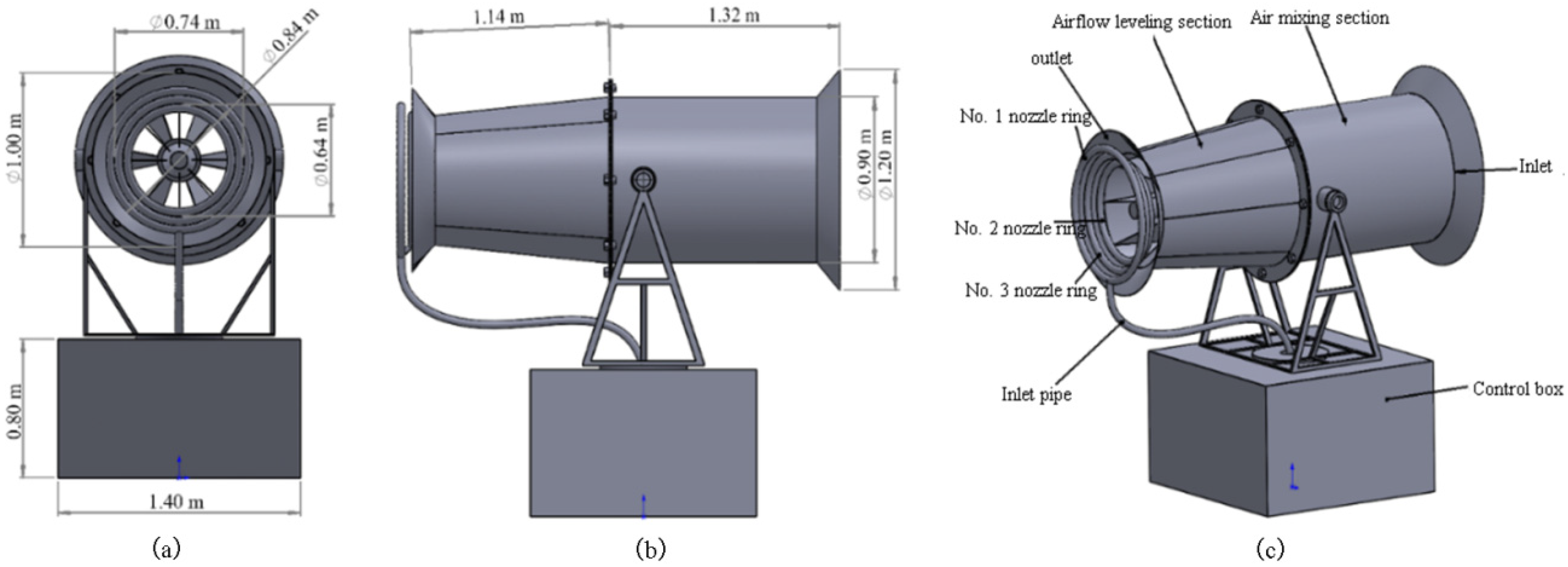
2.1. Physical Model

The JJPW-G100 air-assisted spraying dust suppression device was used for experimental research in this study. The operating wind pressure and wind flow rate were 1230 Pa and 2700 m3/min, respectively. Using Solidworks (Dassault Systemes, Vélizy-Villacoublay, France) a geometrical model with a scale of 1:1 was established for numerical simulation, as shown in Figure 1. From the Figure 1, the air-assisted spraying dust suppression device mainly consists of the axial fan, the air cylinder, the nozzle ring, the control box, and the supported water pipes and valves. To be specific, the fan with a diameter of 0.9 m was placed at the airflow inlet. As regards the air cylinder, the rectifying section and the smoothing section were 1.32 m and 1.14 m in length, respectively; the rectifying plate was installed in the air cylinder, and the diameter of the airflow outlet was 1 m. The forefront end of the air cylinder was a cone. The nozzle ring includes three layers, and the diameters of No. 1, No. 2, and No. 3 nozzle rings were 0.84 m, 0.74 m, and 0.64 m, respectively. Twenty-six nozzles were uniformly installed in each layer. As shown in Figure 2, by selecting the y-axis as the vertical direction of the model, the angle between the central axis of the nozzle and the central axis of the air cylinder can be defined as the installation angle of the nozzle. Next, mesh generation was performed on the established model. Considering the complexity of the established geometrical model, unstructured meshes with strong adaptivity were generated. The size of the element size was set as 1500 mm; the arc-shaped wind deflector and the annular slot were meshed more densely, with a mesh size of 1 mm; the other complex structures were locally densified using meshes with a size of 20 mm. “Mesh quality” is used as an indicator to evaluate the quality of the mesh. As the “mesh quality” value tends to 1, the mesh has better quality. The mesh quality of this model is mostly distributed in the range of 0.4~1.0, and a total of 1,834,659 meshes have a “mesh quality” higher than 0.4, accounting for 99.23% of the total number of meshes [30,31,32,33,34].

2.2. Boundary Condition

When the fan was working, the wind pressure at the air outlet was measured to be 1230 Pa, the wind speed was 45 m/s, and the air volume was 162,000 m3/h; at 5 m from the air outlet, the wind pressure was 780 Pa, the wind speed was 36 m/s, and the air volume was 123,000 m3/h. Water was set as the medium for this simulation. In ANSYS Fluent 2020R1 (ANSYS, Canonsburg, PA, USA) we set the bottom of the nozzle ring as the air outlet and performed the transient calculation of the particles ejected from the nozzle. When the particles hit the wall, they are marked as an escape and are not tracked. The transient tracking time was set to 5 s. The particle size distribution of a single nozzle was set by modifying the parameters so that the simulated particle size of a single nozzle was close to the experimental value.

2.3. Mathematical Model

The related parameters in the boundary condition, source item, and physical model were set in Fluent. Air and liquid can be treated as the continuous phase and the discrete phase, respectively. Using the Standard k-ε turbulence model, no energy exchange occurred between gas and liquid. Moreover, the phase-to-phase coupling calculation was performed based on the TAB break-up model, in which the collision restitution coefficient was set as 0.8. The corresponding mathematical models are described below [35,36,37,38].
The equation of continuity can be written as:
ρ t + d i v ( ρ u ) = 0
where ρ denotes the density, with a unit of kg/m3; t denotes the time, with a unit of s; u are velocity vectors.
The momentum equations can be written as:
( ρ u ) t + d i v ( ρ u u ) = d i v ( μ g r a d u ) p x + S u
( ρ v ) t + d i v ( ρ v u ) = d i v ( μ g r a d v ) p y + S v
( ρ w ) t + d i v ( ρ w u ) = d i v ( μ g r a d w ) p z + S w
The transport equation of the other variables can be written as:
( ρ φ ) t + d i v ( ρ φ u ) = d i v ( Γ g r a d φ ) + S
where φ is a variable, Γ denotes the diffusion coefficient, and S is the source item.
The equation of the discrete phase can be written as:
d u p d t = F d ( u u p ) + g ( ρ p ρ ) ρ p + F
F d = 18 μ ρ p d p 2 C d R e 24
where Fd denotes the unit drag force of droplet, with a unit of N; u denotes the velocity of the continuous phase, with a unit of m/s; up denotes the velocity of droplet, with a unit of m/s; μ denotes the dynamic viscosity of fluid, with a unit of N·s/m2; ρ denotes the density of fluid, with a unit of kg/m3; ρp denotes the density of droplet, with a unit of kg/m3; dp denotes the diameter of droplet, with a unit of m; Re denotes the Reynolds number; g is the acceleration of gravity, with a unit of m/s2; F denotes the other forces mainly including gravity and Saffman force, with a unit of N; C d = a 1 + a 2 R e + a 2 R e 2 denotes the drag coefficient; a1, a2 and a3 were all constants for spherical particles within a certain Reynold number range.

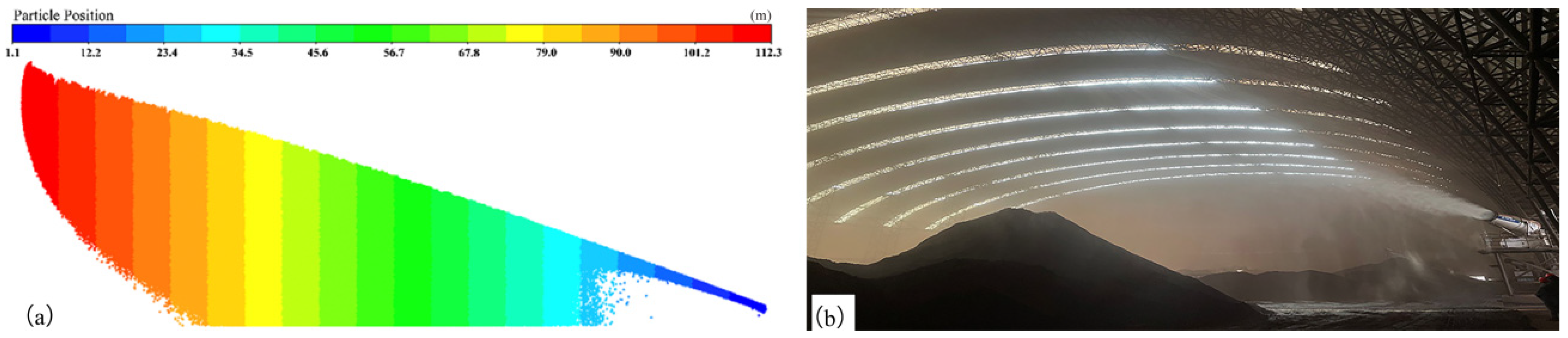
3. Validation of the Effectiveness of the Air-Assisted Spraying Dust Suppression Device Model

Before the numerical simulation, the angle of the air cylinder and the installation angle of the nozzle were fixed as 20° and 45°, respectively, and the water supply pressure was adjusted to 2 MPa. Figure 3 shows the comparison of the spray field between the simulation results and the field condition. From the Figure 3, both two types of results show similar conical field patterns. Droplets dropped with the increasing spraying distance, thereby forming the dust suppression zone. The spraying range of the spray field and the initial falling position of the droplets were measured. Through comparison, the relative error between the simulation and the measured results was within 10%.
In order to further validate the accuracy of the simulation results, both droplet sizes and wind velocity at different positions were measured by the Malvern real-time particle size analyzer (Spectris plc, Egham, UK). The measured positions were arranged 46~76 m away from the spray field, at an interval of 10 m. The Malvern real-time particle size analyzer uses the principle of information optics to analyze the particle size distribution by measuring the scattering spectrum of the particle group. The instrument consists of a data measurement part and a data processing part. The data measurement part includes a laser transmitter and a laser receiver. Since the instrument measurement data is the area of the spray field penetrated by the laser beam, the experiment needs to be placed in the spray field of the air-driven spray device. In addition, in order to obtain stable measurement data, the center point of the acquisition line between the laser transmitter and the laser receiver was set directly in front of the air duct of the air-driven spray device. Table 1 lists the comparison between the measured data and the simulation results.
It can be observed from Table 1 that the relative error of D50 between the simulation data and the measured data was below 11.7%. The simulation data of wind velocity also exhibited a similar variation trend with the measured data, with a maximum relative error of 13.4%. By taking into account limited experimental conditions and the disturbance of external factors in the experimental environment, the experimental values were slightly larger than the simulated data. Through overall comparison, the errors between two atomizing parameters in numerical simulation and the measured data were within the allowable range, which confirmed the effectiveness of the numerical simulation model of the air-assisted spraying dust suppression device.

4. Establishment of the Physical Model and Mathematical Model

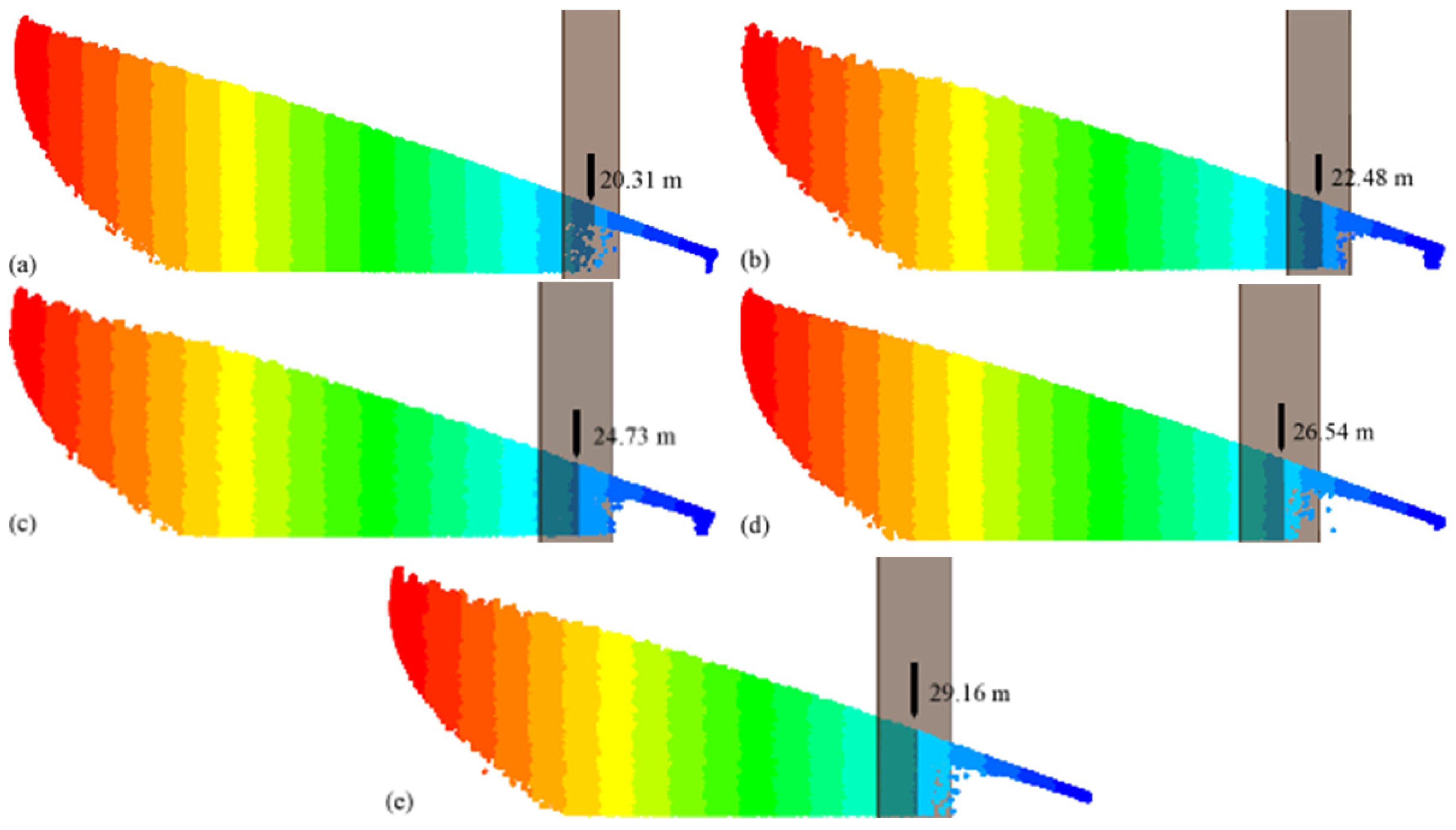
4.1. Effect of the Spraying Range of the Air-Assisted Spraying Dust Suppression Device

The installation angle of the nozzle determines the overlapped area in the spray field of the nozzle rings, thereby affecting collision probability between droplets in the initial spraying phase. Therefore, by varying the installation angle of the nozzle on the nozzle ring, i.e., 0°, 15°, 30°, 45°, and 60°, the atomizing performances of the air-assisted spraying dust suppression device under 5 different conditions were simulated and compared. The spraying range results are shown in Figure 4.
It can be observed from Figure 4 that the spraying range of the air-assisted spraying dust suppression device did not change with the variation of the installation angle of the nozzle. The maximum spraying range was always maintained at approximately 110 m. Since the spraying range of the air-assisted spraying dust suppression device was mainly determined by the spraying angle of the air cylinder and the power of the fan, the installation angle of the nozzle imposed no obvious effect.
Next, an axial plane was established in the spray field of the air-assisted spraying dust suppression device, and the falling ranges at different installation angles of the nozzle were obtained by translating the axial plane, as the results show in Figure 5. From the Figure 5, the falling range increased steadily with the increasing installation angle of the nozzle. At an installation angel of 0°, the falling range was 20.31 m; as the installation angle increased to 60°, the falling range increased to 29.16 m. At a small installation angle of the nozzle, the spraying angle of the spray field at the outlet was large, and the droplets at the edge were merged into large droplets, which thereby accelerated the falling velocity. Meanwhile, as the installation angle increased, the droplet sizes near the nozzle increased gradually, leading to the increase of the droplet inertial force and the falling range. The falling range of the air-assisted spraying dust suppression device is an important parameter. A small falling range at the beginning would result in dispersed droplets, and therefore, the droplet concentration far away from the nozzle was low, which was unfavorable for distant dust suppression. Therefore, the falling range should be enhanced as much as possible during the design and installation of nozzles.

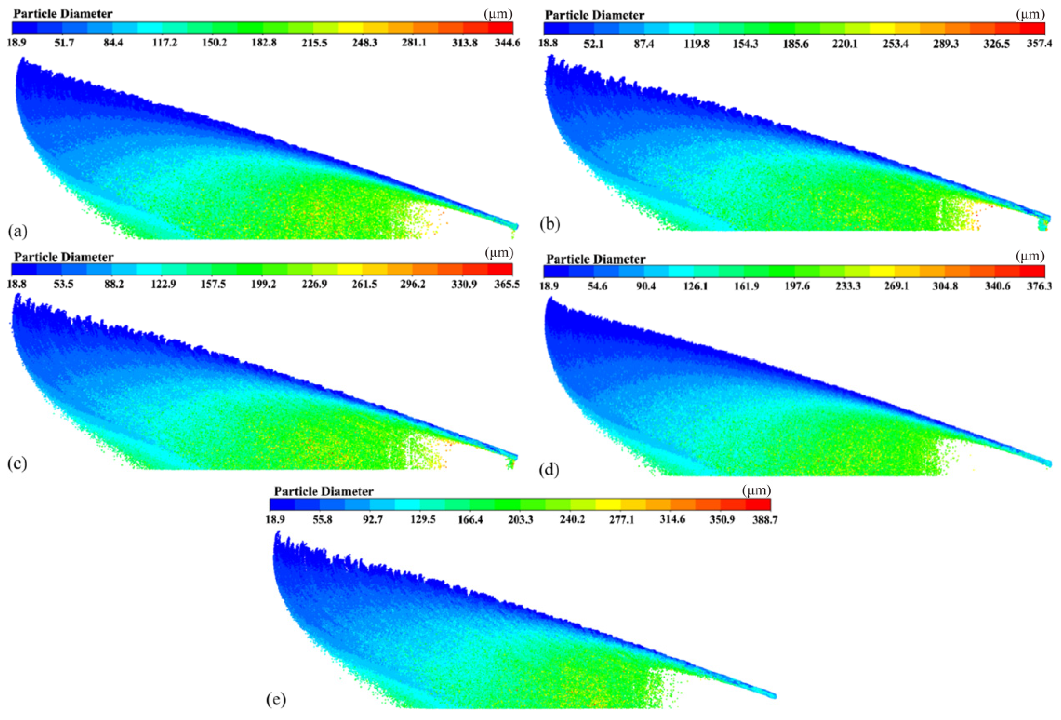
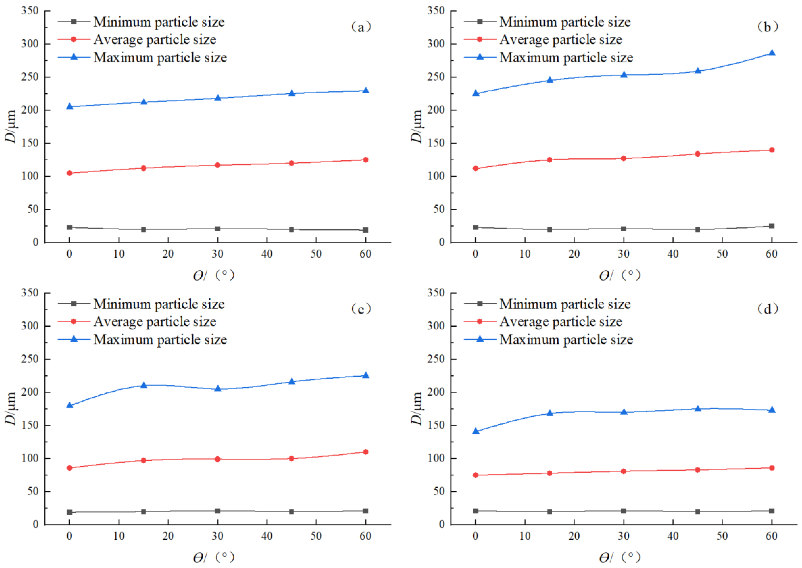
4.2. Effect of the Droplet Size of the Air-Assisted Spraying Dust Suppression Device

Figure 6 shows the droplet sizes in the spray field at different installation angles of the nozzle, from which we can observe that the minimum droplet size in the spray field differed slightly with the increase of the installation angle of the nozzle and maintained at approximately 18 μm. As the installation angle of the nozzle increased, the overlapped area of spraying around the outlet of the nozzle ring increased steadily, and droplets collided more intensively; accordingly, large-size droplets entered into the hybrid spraying section, then further coagulated in the hybrid section under the combined action of wind and airflow, among which the large droplets formed in collision coagulation fell gradually under the gravity. In the meantime, under high-velocity wind flow action, small-size droplets formed by the break-up of large droplets via secondary atomization migrated toward the spraying direction of the air cylinder because of the combined action of wind and airflow, thereby resulting in gradual layering in the spray field. As shown in Figure 6a–c obvious falling of droplets can be observed at the outlet of the spraying device. This is due to the fact that the nozzle rings had small intervals and the droplets ejected from the nozzles on the second and third nozzle rings stuck the nozzle rings. Meanwhile, at a small installation angle of nozzle, the spraying angle of the air-assisted dust suppression device was large at the outlet; accordingly, a portion of droplets at the edge below the nozzle outlet fell under the gravity, thereby causing the loss of part of droplets.
Four cross-sections were cut in the spray fields of the spraying device when the nozzles were installed at different angles on the axial direction from S = 26 m at an interval of 20 m, and the variation curves of the droplet size with the installation angle of the nozzle on different cross-sections in different spray fields were analyzed and plotted, as shown in Figure 7.
As shown in Figure 7a, the minimum droplet sizes in different spray fields on a cross-section remained almost unchanged, while the maximum droplet size and mean droplet size increased with the increasing installation angle. At an installation angle of 0°, the mean droplet size was 101.3 μm; as the installation angle increased to 60°, the mean droplet size increased to 123.7 μm. It can also be observed from Figure 7b–d that the installation angle of the nozzle imposed similar effects on the droplet size on the other three cross-sections. As the installation angle of the nozzle increased, the overlapped area in the spray field increased, and simultaneously, the spraying angle at the nozzle outlet dropped. Therefore, the droplet concentration can be enhanced within a limited spraying range. The droplets aggregated at the nozzle outlet after the collision and easily formed large-size droplets, which can account for the gradual increase of droplet size with the increasing installation angle. Through comparison, it can be concluded that the mean droplet size first increased and then decreased with the increasing spraying range at the same installation angle. At an installation angle of 30°, the mean droplet sizes at a spraying range of 26 m, 46 m, and 88 m were 119.5, 126.2, and 77.6, respectively. As the spraying distance increased, large-size droplets gradually fell, while only small-size droplets floated in the air, leading to the decline in droplet size.
Overall, the installation angle of the nozzle imposed no significant effect on the spraying range, while both mean droplet size and the falling range increased with the increasing installation angle. Therefore, the installation angle should be set to an appropriate value, neither too large nor too small. Meanwhile, according to the simulation results, at an installation angle of below 45°, the falling phenomenon of droplets occurred at the outlet of the air cylinder, leading to partial droplet loss. Through overall consideration, an installation angle of 45° is appropriate.

5. Conclusions

Taking the JJPW-G100 air-assisted spraying dust suppression device as a research object, this study performed a numerical simulation on the spray fields at different installation angles of the nozzle with Fluent and summarized the variation rules of spraying parameters. The simulation results demonstrated that the installation angle of the nozzle imposed no obvious effect on the spraying range of the air-assisted spraying dust suppression device, while the falling range in the spray field increased with the increasing installation angle. As the installation angle of the nozzle increased to over 45°, the loss of droplets at the outlet of the air cylinder disappeared. As the installation angle of the nozzle increased, the mean droplet size increased steadily while the spraying range first increased and then decreased. The optimal installation angle of the nozzle was determined as 45°; at this angle, the loss of droplets at the outlet of the air cylinder in the air-assisted spraying dust suppression device can be effectively avoided while ensuring small droplet size and large falling range. Due to the limited experimental conditions, there are still some shortcomings in this research. Most of the data were obtained by simulation and have not been verified by experiments. The experimental results are in the theoretical stage. The interaction between droplets under multi-nozzle interference has not been studied experimentally.

Author Contributions

Conceptualization, writing—review and editing, H.L.; methodology, validation, J.L.; investigation, writing—original draft preparation, J.W.; funding acquisition, P.W.; visualization, X.Y. and H.H. All authors have read and agreed to the published version of the manuscript.

Funding

This research is funded by the 2019 National innovation and entrepreneurship training program for college students in provincial colleges and universities on Production of renewable environment friendly multifunctional paper and entrepreneurship training development. This research is funded by the 2020 Innovation and entrepreneurship training program for college students in Hunan Province on Environment friendly garbage bag production and entrepreneurship development training grant number 2955.

Institutional Review Board Statement

Not applicable.

Informed Consent Statement

Informed consent was obtained from all subjects.

Data Availability Statement

Publicly available datasets were analyzed in this study.

Conflicts of Interest

The authors declare no conflict of interest.

References

  1. Editorial Department of China Occupational Medicine. National Occupational Diseases report in 2020. China Occup. Med. 2021, 48, 396. [Google Scholar]
  2. Jiang, Z.A.; Zeng, F.B.; Wang, Y.P. Research Status and Prospect of Dust Pollution Control in Typical Working Places During Mining and Transportation of Metal Mines in China. Met. Mine 2021, 50, 135–153. [Google Scholar]
  3. Yang, W.T.; Qiao, P.; Liu, X.Z.; Lei, Y.L. Analysis of Multi-scale Spatio-temporal Differentiation Characteristics of PM 2.5 in China from 2011 to 2017. Environ. Sci. 2020, 41, 5236–5244. [Google Scholar]
  4. Wang, H.; An, D.F.; Zhang, L.L. Analysis on major smoke and dust emission sources in iron and steel enterprise. Environ. Eng. 2016, 34, 62–64. [Google Scholar]
  5. Diao, Y.F.; Lu, Y.; Zhuang, J.W. Special microscopic features of the metallic dust in the welding and cutting areas of the casting and forging workshop. J. Saf. Environ. 2021, 125, 1971–1977. [Google Scholar]
  6. Jia, L.; Wang, D.X.; Zhou, D.; Sun, Y.W.; Liang, B. Experimental test and examination on dust dissipation regularity of chutes in the open pit mine. J. Saf. Environ. 2018, 104, 751–754. [Google Scholar]
  7. Zhou, G.; Zhang, L.C.; Liu, R.L.; Sun, B.; Kong, Y.; Huang, Z.A. Numerical simulation investigation for the pollution characteristics of dust particles in the fully mechanized mining face under different air humidity conditions. J. Environ. Chem. Eng. 2021, 9, 106861. [Google Scholar] [CrossRef]
  8. Xie, Z.W.; Xiao, Y.M.; Jiang, C.X.; Ren, Z.L.; Li, X.Q.; Yu, K.C. Numerical study on fine dust pollution characteristics under various ventilation time in metro tunnel after blasting. Build. Environ. 2021, 204, 108111. [Google Scholar] [CrossRef]
  9. Cai, P.; NIe, W.; Chen, D.W.; Yang, S.B.; Liu, Z.Q. Effect of airflow rate on pollutant dispersion pattern of coal dust particles at fully mechanized mining face based on numerical simulation. Fuel 2019, 239, 623–635. [Google Scholar] [CrossRef]
  10. Zhang, H.H.; Nie, W.L.; Wang, H.K.; Bao, Q.; Jin, H.; Liu, Y.H. Preparation and experimental dust suppression performance characterization of a novel guar gum-modification-based environmentally-friendly degradable dust suppressant. Powder Technol. 2018, 339, 314–325. [Google Scholar] [CrossRef]
  11. Wang, P.F.; Chang, T.; Liu, R.H.; Wang, J. Mathematical model for multivariate nonlinear prediction of SMD of X-type swirl pressure nozzles. Process Saf. Environ. Prot. 2019, 125, 228–237. [Google Scholar] [CrossRef]
  12. Xu, G.; Chen, Y.P.; Eksteen, J.; Xu, J.L. Surfactant-aided coal dust suppression: A review of evaluation methods and influencing factors. Sci. Total Environ. 2018, 639, 1060–1076. [Google Scholar] [CrossRef] [PubMed]
  13. Yin, W.J.; Zhou, G.; Gao, D.H. Simulation analysis and engineering application of distribution characteristics about multi-stage atomization field for cutting dust in fully mechanized mining face. Adv. Powder Technol. 2019, 30, 2600–2615. [Google Scholar] [CrossRef]
  14. Wang, H.T.; Wei, X.B.; Du, Y.H.; Wang, D.M. Experimental investigation on the dilatational interfacial rheology of dust-suppressing foam and its effect on foam performance. Process Saf. Environ. Prot. 2019, 123, 351–357. [Google Scholar] [CrossRef]
  15. Zhou, W.J.; Nie, W.; Liu, C.Q.; Liu, Q.; Wang, H.T.; Wei, C.H.; Yan, J.Y.; Yin, S.; Xiu, Z.H.; Xu, C.W. Modelling of ventilation and dust control effects during tunnel construction. Int. J. Mech. Sci. 2019, 160, 358–371. [Google Scholar] [CrossRef]
  16. Liu, Q.; Nie, W.; Hua, Y.; Jia, L.B.; Li, C.S.; Ma, H.; Wei, C.H.; Liu, C.Q.; Zhou, W.J.; Peng, H.T. A study on the dust control effect of the dust extraction system in TBM construction tunnels based on CFD computer simulation technology. Adv. Powder Technol. 2019, 30, 2059–2075. [Google Scholar] [CrossRef]
  17. Zhang, X.T. Test study on distribution of space flow field of air-assisted long range sprayer. Min. Processing Equip. 2015, 43, 122–125. [Google Scholar]
  18. Zhang, X.T. Study on the distribution law of droplet diffusion and deposition of Long range air-assisted sprayer. Min. Saf. Environ. Prot. 2019, 46, 5–9. [Google Scholar]
  19. Jiang, H.; Guo, R.L.; Zhu, J.T. Two-phase jet flow field of remote spray dust removal. J. Xi’an Univ. Sci. Technol. 2019, 39, 249–255. [Google Scholar]
  20. Wang, L.L.; Wang, Y.L.; Xing, G.P.; Yan, C.M. A dust suppression hydraulic drive car fan structure optimization design. Spec. Purp. Veh. 2017, 4, 87–89. [Google Scholar]
  21. Zhou, H.W.; Zhang, P.; Li, B.; Zhao, Z.Y. Design and analysis of spraying pipeline system in mist cannon truck. Spec. Purp. Veh. 2019, 99–101. [Google Scholar]
  22. Chai, S.J.; Wang, H.Q.; Zhang, Y.Y.; Fan, C.J. Experimental method on static and dynamic balance of fog gun impeller. Spec. Purp. Veh. 2019, 84–86. [Google Scholar]
  23. Wang, Y.Z. Development of a dust suppression fog system and its application in driving face. China Energy Environ. Prot. 2019, 41, 54–57. [Google Scholar]
  24. Tao, T.; Wei, X.H. Numerical Simulation and Analysis of Flow Field in Five—Finger Sprayer of Orchard Sprayer. J. Agric. Mech. Res. 2020, 42, 40–45. [Google Scholar]
  25. Wen, Y.H.; Zhang, E.H.; Huang, J.H.; Li, H.Q. Research on the Suppression Effect of the Mist Cannon Truck on PM10. Automob. Appl. Technol. 2020, 10, 184–186. [Google Scholar]
  26. Cheng, X.J.; Yang, P.Y.; Yang, Z. Finite Element Analysis for Air Cannon Blade of a Dust Suppression Vehicle. Automob. Parts 2018, 2, 62–64. [Google Scholar]
  27. Xu, H.P.; Xing, F.T.; Mei, D.; Yang, Y.L. Research on Spray Parameters of Dust Suppression Vehicle Based on Numerical Simulation. Comput. Simul. 2019, 36, 142–145. [Google Scholar]
  28. Wang, P.F.; Zhang, K.; Liu, R.H. Influence of air supply pressure on atomization characteristics and dust-suppression efficiency of internal-mixing air-assisted atomizing nozzle. Powder Technol. 2019, 355, 393–407. [Google Scholar] [CrossRef]
  29. Li, H.X.; Liu, Q.Z.; Liu, Y.P.; Zhang, J.L. Numerical simulation on atomization characteristics of ultrasonic vibration nozzle based on CFD. Chin. J. Vac. Sci. Technol. 2017, 37, 113–117. [Google Scholar]
  30. Liu, X.J.; Ru, Y. Numerical Simulation and Experiment for Air-assisted Spraying Fan. For. Mach. Woodwork. Equip. 2019, 47, 9–13. [Google Scholar]
  31. Kim, K.D.; Jin, D.H.; Choi, Y.C. Numerical simulation on the generation of ultrasound and formation of water fog in the ultrasonic gas atomizer. Ultrasonics 2020, 102, 105851. [Google Scholar] [CrossRef] [PubMed]
  32. Zhou, G.; Yin, W.J.; Feng, B. Numerical simulation on the distribution characteristics of dust-droplet field dur-ing support movement in a fully-mechanized mining face and related engi-neering applications. J. China Coal Soc. 2018, 43, 3425–3435. [Google Scholar]
  33. Wang, P.F.; Li, Y.J.; Liu, R.H.; Shi, Y.J. Effect of forced-to-exhaust ratio of air volume on dust control of wall-attached swirling ventilation for mechanized excavation face. Tunn. Undergr. Space Technol. 2019, 90, 194–207. [Google Scholar] [CrossRef]
  34. Li, Y.J.; Wang, P.F.; Liu, R.H.; Jiang, Y.D.; Han, H. Determination of the optimal axial-to-radial flow ratio of the wall-mounted swirling ventilation in fully mechanized excavation face. Powder Technol. 2020, 360, 890–910. [Google Scholar] [CrossRef]
  35. Wang, P.F.; Shi, Y.J.; Zhang, L.Y.; Li, Y.J. Effect of structural parameters on atomization characteristics and dust reduction performance of internal-mixing air-assisted atomizer nozzle. Process Saf. Environ. Prot. 2019, 128, 316–328. [Google Scholar] [CrossRef]
  36. Li, Y.J.; Wang, P.F.; Liu, R.H.; Gao, R.Z. Optimization of structural parameters and installation position of the wall-mounted air cylinder in the fully mechanized excavation face based on CFD and orthogonal design. Process Saf. Environ. Prot. 2019, 130, 344–358. [Google Scholar] [CrossRef]
  37. Han, H.; Wang, P.F.; Li, Y.J.; Liu, R.H.; Tian, C. Effect of water supply pressure on atomization characteristics and dust-reduction efficiency of internal mixing air atomizing nozzle. Adv. Powder Technol. 2020, 31, 252–268. [Google Scholar] [CrossRef]
  38. Han, H.; Wang, P.F.; Liu, R.H.; Tian, C. Experimental study on atomization characteristics and dust-reduction performance of four common types of pressure nozzles in underground coal mines. Int. J. Coal. Sci. Technol. 2020, 3, 581–596. [Google Scholar] [CrossRef]
Figure 1. Model diagram of air-assisted spraying dust suppression device, (a) front view, (b) right view, (c) main view.
Atmosphere 13 00520 g001
Figure 2. Schematic diagram of nozzle angle.
Atmosphere 13 00520 g002
Figure 3. Comparison of spray field simulation results and experiment, (a) simulation results of spray field, (b) spray field real shot.
Atmosphere 13 00520 g003
Figure 4. Variation of the range of spray field with the installation angle of nozzle, (a) ϴ = 0°, (b) ϴ = 15°, (c) ϴ = 30°, (d) ϴ = 45°, (e) ϴ = 60°.
Atmosphere 13 00520 g004
Figure 5. The falling range of the air-assisted spraying dust suppression device at different installation angles of nozzle, (a) ϴ = 0°, (b) ϴ = 15°, (c) ϴ = 30°, (d) ϴ = 45°, (e) ϴ = 60°.
Atmosphere 13 00520 g005
Figure 6. Variation of droplet size in spray field with installation angle of nozzle, (a) ϴ = 0°, (b) ϴ = 15°, (c) ϴ = 30°, (d) ϴ = 45°, (e) ϴ = 60°.
Atmosphere 13 00520 g006
Figure 7. Variation of droplet size on different cross-sections with installation angle nozzle, (a) S = 26 m, (b) S = 46 m, (c) S = 66 m, (d) S = 86 m.
Atmosphere 13 00520 g007
Table 1. Comparison of measured data and simulation results of wind speed and particle diameter in each panel.
Spraying Range S/mMeasured DataSimulation DataRelative Error/%
Wind Velocity/(m/s)D50/μmWind Velocity/(m/s)D50/μmWind Velocity D50
462.11153.651.86138.7511.89.7
561.89124.001.65111.4812.710.1
661.57109.291.36100.3313.48.2
761.03101.451.1289.588.111.7
Publisher’s Note: MDPI stays neutral with regard to jurisdictional claims in published maps and institutional affiliations.

