Article

Development of Dust Collectors to Reduce Brake Wear PM Emissions

Eco-Friendly Energy Conversion Research Division, Korea Institute of Machinery and Materials, Daejeon 34103, Korea
*
Author to whom correspondence should be addressed.
Atmosphere 2022, 13(7), 1121; https://doi.org/10.3390/atmos13071121
Submission received: 22 June 2022 / Revised: 11 July 2022 / Accepted: 14 July 2022 / Published: 15 July 2022
(This article belongs to the Special Issue Brake Wear Particulate Matter and Mitigation Strategies)

Abstract

:
In this study, two different dust collectors, one based on an inertial separator and the other based on an electrostatic precipitator (ESP), were developed in order to reduce brake wear particulate matter (PM) emissions. Additionally, the collection efficiencies for brake wear particles (BWPs) of the inertial separator and the ESP were evaluated according to brake pad type. In the case of the inertial separator, the BWP collection efficiencies for the low-metallic (LM) and non-asbestos organic (NAO) pads were similar, and the cut-off size at 50% collection efficiency (D50) was 2.2 µm. The ESP was designed without an additional electrostatic charging device because naturally induced electrostatic charging occurred due to the friction between the brake disc and pad. The BWP collection efficiency of the ESP was higher for NAO pad than for LM pad because the BWPs generated from the NAO pad contained a relatively low iron (Fe) component compared to that of the LM pad, thereby generating more frictional electricity. The maximum ESP collection efficiencies of the BWPs generated from the LM and NAO pads were determined to be 60% and 75%, respectively, and the remaining BWPs that were not collected were presumed to be particles that were not frictionally charged.

1. Introduction

Non-exhaust particulate matter (PM) emissions from road traffic can be generated as a result of the wearing down of brakes, clutches, tires, road surfaces, as well as road dust resuspension [1]. While worldwide global regulations for exhaust PM emissions are becoming more stringent, non-exhaust PM emissions are still unregulated. As a result, the amount of exhaust PM has continuously decreased, while the relative contribution of non-exhaust PM emissions has increased. Non-exhaust emissions are expected to be responsible for the vast majority of PM emissions from road traffic in future years [2,3]. It has been reported that 19%, 33%, and 31% of traffic-related PM emissions are generated from brakes, tires, and road pavement, respectively, and only 17% of PM is generated from vehicular exhaust [4]. Lawrence et al. [5] estimated the emission factor (EF) of exhaust and non-exhaust PM emissions in a tunnel experiment. The EF had a range of 11.1–12.8 mg/v.km and 16.7–19.3 mg/v.km for exhaust and non-exhaust PM emissions, respectively, which showed that non-exhaust PM emissions exceeded exhaust PM emissions in terms of road traffic sources.
Multiple studies have reported that brake wear particles (BWPs) are the most significant emissions source among various non-exhaust PM sources. It has been estimated that 21% of road-traffic-related PM10 in the urban environment is generated from the wearing down of brakes [6], and that BWP EF is distributed with a large fluctuation that ranges from 1 to 18.5 mg/v.km [7]. Moreover, it is known that exposure to BWPs could result in adverse health effects, such as acute respiratory infections, lung cancer, and chronic respiratory and cardiovascular diseases [8].
As it is known that BWPs have a significant impact not only on urban air quality but also on adverse health effects, the movement to regulate BWPs is increasing. In June 2020, the Particle Measurement Program (PMP) group of the United Nations Economic Commission for Europe (UNECE) published a protocol for measuring BWPs, which incorporates the driving cycle into BWP measurements; the protocol also provides a procedure for brake pad burnishing, in addition to methods for measuring brake disc and pad temperatures. Currently, a round robin testing campaign is being initiated to control the repeatability (within the labs) and reproducibility (among the labs) of PM and particle number (PN) measurements with the application of the proposed specifications. Based on a reliable testing method for measuring BWPs, the upcoming Euro 7 emission standard will regulate not only exhaust PM emissions, but also brake wear PM emissions.
Various studies, including those that concern improvements in the materials that constitute brake discs and pads, coating the brake disc surface with an additional material, resizing the brakes, use of drum brakes, regenerative braking, and aftertreatment devices to directly collect BWPs, have all been conducted in order to reduce brake wear PM emissions [9]. Generally, it is known that BWPs can be significantly reduced by using non-asbestos organic (NAO) brake pads rather than low-metallic (LM) brake pads [10,11]. The addition of a zinc (Zn) component to the brake pad material could reduce brake wear [12], and coating the brake disc surface with nickel (Ni) could enhance wear resistance [13]. Additionally, increasing the binding resin content leads to improved abrasion resistance of the brake pads and reduces their particle emissions under high-temperature conditions [14]. Regenerative braking reduces the use of frictional braking, and hence brake wear PM emissions, in proportion to the regenerative braking intensity [15].
In regards to directly reducing brake wear PM emissions, several aftertreatment devices have been proposed. Tallano technology developed a brake particle collection system designed to trap at least 80% of brake particles directly at the pad–disc interface without altering braking efficiency. The collection system is composed of a brake caliper that is specially designed for the integration of grooved pads and of an aspiration system where brake particles are trapped [16]. Mann+Hummel group [17] also unveiled a BWP collection system that uses a passive filter. The passive brake dust particle filter with non-woven metal fibers is fitted directly onto the caliper, and directly retains particle emissions on the brake. In a similar manner, Hwang and Lee [18] removed BWPs by installing a passive filter behind the brake caliper. However, these particle-removing methods have a major drawback. BWPs consist of huge numbers of micron-sized particles [19] which constitute a significant PM mass, and as a result the filter can eventually become saturated with them in a short period of time; this makes the replacement cycle of the filter short and the maintenance cost high.
In this study, two different dust collectors were developed in order to reduce brake wear PM emissions. An electrostatic precipitator (ESP) that collects BWPs using the frictional electricity generated from the friction between the brake pad and its disc, and an inertial dust separator that collects relatively larger micron-sized particles, were designed. Their collection efficiencies were evaluated according to different brake pad types. Finally, a hybrid dust collector, which connects the electrostatic precipitator and the inertial separator in series, was tested under the WLTP-brake driving cycle in order to evaluate its maximum collection efficiency.

2. Materials and Methods

2.1. Designing the Dust Collectors for BWPs

Both the ESP and inertial separator were designed to remove BWPs. First, the inertial separator was designed based on BWP characteristics. Many previous studies have reported that most of the mass concentration of BWPs is composed of micron-sized particles [19,20]. The inertial separator is advantageous for removing BWPs because it is specialized to remove micron-sized particles. Additionally, it is suitable for removing BWPs that are generated in large amounts in terms of volume and mass, since the separator can continuously remove a large amount of dust. Large flow resistance is a disadvantage of the inertial separator. Large flow resistance is induced by a change in flow direction, which contributes to separating particles. The inertial separator can classify particles based on Stokes number (Stk), which is a non-dimensional number composed of inertial and particle moving distance [21]. The Stk number is defined as follows:
Stk = ρ p d p 2 C c U 9 μ W        
where ρp is the particle density, dp is the particle diameter, Cc is the slip correction factor, µ is the viscosity of air, U is the flow velocity, and W is the distance of streamline inflection, usually the nozzle width. A 50% cut-off size indicates the particle aerodynamic diameter when the collection efficiency is 50%. The inertial separator’s collection efficiency is increased as the 50% cut-off size decreases. BWPs usually have a 2–4-micrometer mode diameter in particle mass distribution [19,20]. Therefore, the 50% cut-off size of the inertial separator should be smaller than BWPs’ mass distribution mode diameter, 2–4 µm. Stk501/2, which is the Stokes number that meets the 50% cut-off size, is fixed at 0.77 in slit impactor laminar flow conditions [21]. Generally, Stk501/2 is not changed in a Reynolds number range of 500 to 3000 [22]. In order to decrease dp in Equation (1) for the same Stk501/2, particle density ρp or flow velocity U must be increased, or the streamline inflection distance W must be decreased. Flow velocity U and streamline inflection distance W can be controlled easily. However, increasing flow velocity induces great flow resistance, whereas decreasing W can decrease the 50% cut-off size without greatly increasing flow resistance. However, if the structure of the inertial separator is decreased under the limited strength, it can be broken by flow resistance. Therefore, in this study, W was designed to be as small as possible within the limit of structural strength in order to minimize the 50% cut-off size. In this study, the nozzle width used was 1 mm, as shown in Figure 1a. The collection surface was replaced with the dust receiver in order to collect particles continuously in the long-term. The particle diameter of 0.77 Stk1/2 of the designed inertial separator was 3.25 µm. Kim et al. [23] reported that Stk501/2 was decreased to 0.6 when the collecting plate was elliptical-concave. It was expected that the dust receiver designed in this study would decrease Stk501/2. Furthermore, during turbulent flow, the impactor collection efficiency curve was expected to broaden [24]. Therefore, the collection efficiency of the inertial separator designed in this study would be different from the traditional impactor collection efficiency curve, because strong turbulence was contained at the inflow of the inertial separator.
BWPs are emitted broadly, with sizes ranging from 6 nm to 10 µm [25]. The ESP has great dust collection performance, from micron-sized particles to nanoparticles [26]. Generally, particles flowing into an ESP are charged by extreme high voltage corona discharge, and the charged particles are then removed into a collecting plate. However, BWPs can already be charged by triboelectricity [27]. Therefore, it was expected that BWPs could be removed by the ESP without requiring corona discharge. If the corona charging part can be omitted, then the high voltage from corona charging in the ESP is no longer required, and hence ozone emissions could be greatly decreased. Therefore, ESP collecting plates (ground plates) and high-voltage plates are alternately arranged in this study, as shown in Figure 1b. The collecting plates and high-voltage plates were created using 0.5-millimeter-thick aluminum sheets coated with polyethylene terephthalate (PET) film. Breakdown risk is decreased and the supplied voltage can be increased when these ESP plates are coated with a dielectric layer [28]. In addition, high dust collection efficiency can be maintained for a long time when the plates are coated with dielectric material [26]. The distance between the collecting plate and the high-voltage plate was 4.5 mm. In total, 11 high voltage plates and 12 collecting plates were installed in the ESP.

2.2. Brake Dynamometer

Figure 2 shows a schematic diagram of the brake dynamometer and test setup used to determine the BWP collection efficiency of the ESP and the inertial separator. The rotating weight was 120 cm in diameter and had a mass of 280 kg,; it was installed on the brake dynamometer axis. The rotation simulated a moment of inertia of 50.4 kg m2, equivalent to the vehicle curb weight plus one passenger, and assuming a brake force distribution (BFD) of 7/3 between the front and rear brakes [11]. The vehicle speed was calculated based on 16-inch wheels fitted with 205/65 tires. The dynamometer could simulate vehicle speeds of up to 150 km/h. The brake disc was composed of cast iron and was 30 cm in diameter. NAO-type and LM-type brake pads were used in this study. Both the ESP’s and the inertial separator’s performances for the NAO and LM pads were tested. Brake oil pressure was activated at 1–50 bar. Brake disc rotating speed and brake pressure were automatically controlled according to a time–speed schedule. Brake disc temperature was measured using a non-contact infrared thermometer (LT-SF-CB3, Optris, Berlin, Germany) that was placed at the disc surface behind the brake caliper. The infrared thermometer measured the average temperature of a circular area 3 cm in diameter on the brake disc surface behind the friction surface between the pad and the disc. Considering that the accuracy of the infrared thermometer was insufficient compared to the sliding or embedded thermocouples, the absorptivity of the brake disc material was experimentally determined by comparing the infrared thermometer reading with that of a k-type thermocouple, in order to ensure the reliability of the infrared thermometer.
The world harmonized light-duty test cycle (WLTC, Tutuianu et al. [29], Figure 3a) and the world harmonized light vehicles test procedure for brake emissions (WLTP-brake, Mathissen et al. [30], Figure 3b) were used in this study. Originally, the WLTC was developed to evaluate exhaust emissions; however, multiple studies have used the WLTC to measure BWPs emissions [11,19,20]. Notably, Woo et al. [19] reported that the highest emission factor of BWPs was measured when using the WLTC. In this study, the WLTC was used to test the dust collection performance of both the inertial separator and the ESP, because the cycle length was as short as 30 min. Meanwhile, the WLTP-brake is the standard cycle to evaluate BWPs emissions, which was determined by the PMP group of the UNECE. Therefore, the WLTP-brake was used to evaluate BWP EFs of the final hybrid version of the combined ESP and inertial separator.

2.3. BWP Collection Efficiency Measurement Method

The ESP or the inertial separator was installed in the middle of a 100 mm × 100 mm square wind tunnel, downstream of the brake dynamometer circular chamber. The differential pressure of the ESP or the inertial separator was measured based on the static pressure difference between upstream and downstream regions. The static pressure difference was measured using a pressure measurement module (MP210-MPR2500, KIMO, Montpon, France). Circular wind tunnel flow velocity was measured by a pitot tube placed at a point in the circular cross-section. The face velocity of the ESP or the inertial separator was calculated as a product of the pitot tube value and the cross-sectional area ratio. The pitot tube values fluctuated because wind tunnel flow was turbulent. The fluctuations in flow velocity and differential pressure were less than ±5%. Particle concentration was measured using particle measurement instruments that were located downstream from the ESP or the inertial separator. A particle sampling inlet was designed to satisfy isokinetic sampling. An aerodynamic particle sizer (APS, 3321; TSI, Shoreview, MN, USA), electrical low-pressure impactor (ELPI; Dekati, Tampere, Finland), and a condensation particle counter (CPC, 3775; TSI, USA) were used to measure particle concentrations. The APS measured particle concentrations from 0.52 to 19.8 µm based on aerodynamic diameter. BWPs had to be diluted 20 times with a diluter because their concentration exceeded the APS measurement range. Woo et al. [17] reported that APS measurement of BWPs concentration showed good agreement with the gravimetric method. Therefore, an APS was mainly used to evaluate the ESP’s and the inertial separator’s performances. An ELPI measured a particle size range of 6 nm to 10 µm using an electrometer. The ELPI classified particle size based on an aerodynamic diameter. Additionally, particle charge could be measured by the ELPI [31]. The BWPs’ charge numbers were measured using the ELPI when testing with the LM and NAO pads. A CPC measured a particle total number concentration larger than a certain size, normally 6 nm. The CPC measurement results were compared with the ELPI’s number concentration values, and we evaluated whether the ELPI was affected by electrons and ions that were generated from the ESP.
ESP particle collection efficiency, EFESP,dp at particle size dp, was calculated as follows:
EF ESP , d p = 1 C on ,   d p C off , d p    
where Con,dp and Coff,dp are particle number concentrations at particle diameter dp when the ESP is activated or not, respectively. The ESP was tested for face velocities of 5.3 m s−1, 8.8 m s−1, and 12.4 m s−1, which represented the low, medium, and high velocity conditions in this study, respectively.
The inertial separator particle collection efficiency, EFis,dp, was calculated as follows:
EF is , d p = 1 C is ,   d p C non , d p      
where Cis,dp and Cnon,dp are the particle number concentrations at particle diameter dp when the inertial separator is installed or uninstalled, respectively. The differences in face velocities according to the presence or absence of the inertial separator were less than 5%. Only the 5.3 m s−1 face velocity condition was tested for the inertial separator because its differential pressure was too high. All experiments were repeated three times to remove uncertainty.
Since no corona charging part was used in this study, the BWP collection efficiency of the ESP was insufficient, especially for the larger particles. Hence, a hybrid precipitator, which is a combination of the ESP and the inertial separator, was used to maximize BWP collection efficiency. The ESP was installed upstream and the inertial separator was installed downstream. The hybrid precipitator particle collection efficiency, EFh,dp, was calculated as follows:
EF h , d p = 1 C h ,   d p C non , d p  
where Ch,dp is the particle number concentration at particle diameter dp when the hybrid precipitator is installed. Additionally, EFh,dp can be calculated using previous test results, EFESP,dp and EFini,dp, as follows:
EF h , d p = 1 1 EF ESP , d p × 1 EF ini , d p  
Only the 5.3 m s−1 face velocity condition was tested for the hybrid precipitator, since its differential pressure was too high.

3. Results and Discussion

The differential pressure versus face velocity curves of the ESP and the inertial separator are shown in Figure 4. The differential pressure of the inertial separator was as high as 470 Pa for a face velocity of 5 m s−1; the differential pressure of the ESP was as low as 30 Pa for that same face velocity.
Particle mass and number concentration distribution of BWPs when using the LM pad and the NAO pad are shown in Figure 5. The particle number concentration lower than 23 nm measured by the ELPI fluctuated largely due to electrometer noise. Therefore, a measurement value of the ELPI larger than 23 nm was used in this study. The measurement results from the ELPI and the APS agreed very well with each other because the two instruments classified particles based on aerodynamic diameter. The mode diameters of BWP mass distributions were 4 µm and 2 µm when using the LM pad or the NAO pad, respectively. Park et al. [20] as well as Woo et al. [11] also reported that BWPs from the LM pad were larger than those from the NAO pad.
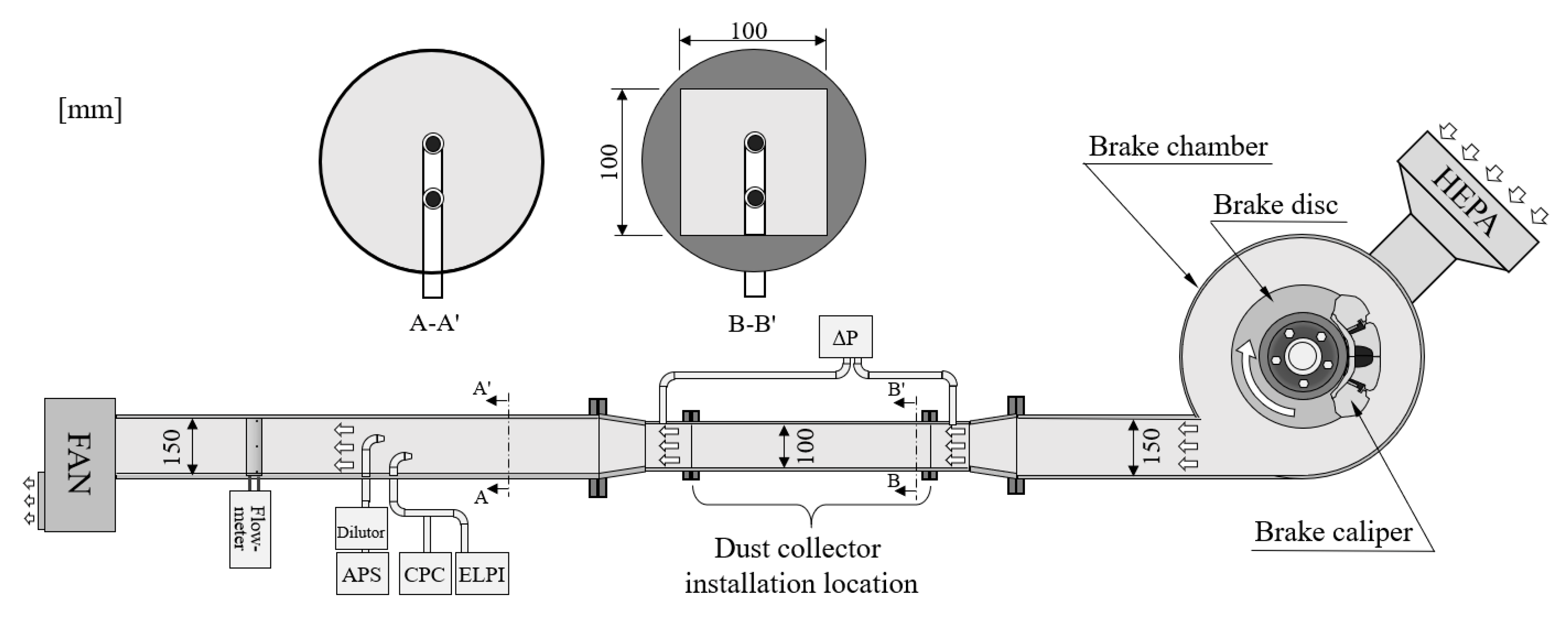
Figure 6 shows the particle number concentration variation measured by the CPC and the ELPI during the WLTP-brake. A high-efficiency particulate air (HEPA, Class H13 99.95%) filter was installed at the inlet of the brake circular chamber in order to decrease, as much as possible, background particles. Background particle number concentration was about 100 particles cm−3. Variations in nanoparticle number concentrations measured by the ELPI and the CPC agreed well with each other. However, at the moment when many BWPs were emitted, the ELPI measured particle number concentrations became 1.5–2 times higher than those from the CPC. It was estimated that the triboelectric effect of BWPs affected the ELPI’s electrometer measurement. However, since mass concentration distributions of the ELPI and the APS agreed, it was estimated that the triboelectricity from the BWPs did not affect the micron-sized particle measurements of the ELPI.
The mode diameters of BWP number concentrations were 1.56 µm and 1.15 µm when using LM and NAO pads, respectively. The particle number concentration distributions were consistently shown in repeated experiments to be above 200 nm. However, the uncertainties in the distributions were high below 200 nm. The highest disc surface temperature in this study experiment was 150 °C. Farwick zum Hagen et al. [32] reported that brake pad temperature should exceed critical temperature in order to generate brake nanoparticles through the evaporation/condensation process. The critical temperature from previous studies was 180–240 °C according to experimental conditions [6]. In our experiments, surface temperature did not exceed critical temperature, and therefore nanoparticles smaller than 200 nm were almost not generated at all. Since it was confirmed that particle mass was mainly discharged from micron-sized particles for both the LM and NAO pads, particle collection efficiency was calculated from the APS measurement results.
Figure 7 shows the particle collection efficiency distribution of the inertial separator. The particle collection efficiency distributions of BWPs from the LM and NAO pads were almost identical because the inertial separator classifies particle size based on aerodynamic diameter. The 50% cut-off size was determined to be 2.2 µm. Unlike the typical inertial separator collection efficiency curve, collection efficiency decreased to 50% when the particle size was larger than 3 µm. The separator’s collection efficiency increased to 80% from 5 µm to 10 µm. It was estimated that coarse particle collection efficiency decreased due to the bouncing problem, or that particles became resuspended from the particle receiver as a result of turbulence. The BWP emissions reduction was calculated by combining the collection efficiency of the inertial separator (Figure 7) and the particle mass size distribution (Figure 5a). The BWP emissions reduction of the inertial separator when using the LM pad was higher than 50% because the mode diameter of the particle mass distribution was larger than the 50% cut-off size. However, the BWP emissions reduction for the NAO pad reached as low as 40%, since its mode diameter was smaller than the 50% cut-off size.
Since BWPs are charged by triboelectricity, collecting parts of the ESP were solely installed. First, ESP collection efficiency was measured for various face velocities, namely 5.3 m s−1, 8.8 m s−1, and 12.4 m s−1. The applied voltage to the ESP was negative 10 kV, and the electric field strength was 22.2 kV cm−1. BWPs were collected on the ESP’s collecting plate, as shown in Figure 8, even though BWPs were not additionally electrically charged. Similarly with traditional ESPs, the collection efficiency of this ESP decreased as face velocity increased. However, its collection efficiency curves were not similar to those of traditional ESPs. Generally, ESP collection efficiency curves appear to be U-shaped, with the lowest collection efficiency occurring for 300 nm [24]. However, the collection efficiency of the ESP used in this study was almost constantly from 520 nm to 3–5 µm. It was estimated that BWPs were not fully charged by triboelectricity, and that the BWPs did not have enough electrophoresis mobility. The ESP collection efficiency when using the NAO pad was higher than that for the LM pad. The average collection efficiencies from 520 nm to 5 µm when using the LM and NAO pads were 52% and 64%, respectively, at a face velocity of 5.3 m s−1. If face velocity was increased to 12.4 m s−1, the collection efficiency when testing with the LM pad decreased to 10%, and that for the NAO pad decreased to 30%. The ESP collection efficiency difference according to pad type was due to different charge numbers on particles. Figure 9 shows the average numbers of charges on BWPs for LM and NAO pads measured by the ELPI. It was shown that the number of charges when using the NAO pad was higher than that for the LM pad. Woo et al. [11] reported that the Fe composition ratio of BWPs when using the NAO pad was only 40%, and other components such as Ti, Ca, Ba, and Si were largely contained in BWPs. The Fe composition ratio of BWPs when using the LM pad was above 60%, and there were almost no other elements. Generally, triboelectricity occurs when different materials rub against each other [33]. The brake pads rubbed against brake discs made of cast iron. Therefore, it was estimated that BWPs when using the LM pad would be only slightly frictionally charged, since the LM pad and brake disc materials were similar; however, the BWPs emitted from the NAO pad would be highly frictionally charged since the NAO pad material was different to the material of the brake disc. Therefore, the ESP collection efficiency could be changed if the brake disc material was changed.
When using the LM pad, collection efficiency decreased as BWP size increased above 3 µm. The reason for this is because the number of charges in BWPs decreased as BWP size increased. It was estimated that the Fe composition ratio in BWPs when using the LM pad increased as BWP size increased; therefore, triboelectricity decreased as BWP size increased. However, the BWP collection efficiency when using the NAO pad increased as the BWP size increased from 520 nm to 5 µm. The reason for this is because the number of charges on BWPs increased as BWP size increased. The increasing number of charges on BWPs as size increases was due to the Fe composition ratio decreasing as BWP size increased. Woo et al. [11] reported that Fe components were mainly observed in sub-micron BWPs, and potassium hexatitanate (PHT, K2Ti6O13) was the main component of micron-sized BWPs. It was estimated that micron-sized BWPs emitted from the NAO pad were suitably frictionally charged since they contained a lot of PHT. The ESP’s BWP collection efficiency for the NAO pad decreased as BWP size increased above 5 µm when the face velocities were 8.8 m s−1 and 12.4 m s−1. The reason for this was because the face velocity was too fast to collect large BWPs which were not charged enough. The BWP collection efficiency of the ESP increased as BWP size increased above 5 µm when the face velocity was 5.3 m s−1 since there was sufficient time for electrophoresis movement.
Looking at the collection efficiency curve for various applied voltages, it can be seen more clearly that BWPs were not frictionally charged enough, as shown in Figure 10. The collection efficiency of the ESP increased as applied voltage increased from 2 kV to 10 kV, because BWPs were more strongly pulled by the electric field strength. However, the collection efficiency of the ESP did not increase further when applied voltage was increased from 10 kV to 15 kV. This means that frictionally charged BWPs were almost all collected by the ESP under an applied voltage of 10 kV. The BWPs that were not collected by one ESP with an applied voltage of 10 kV were particles which cannot be removed by the ESP, in other words, non-charged particles.
The BWP collection efficiency increased as applied voltage increased from 2 kV to 10 kV for all particle sizes when using the NAO pad. The BWP collection efficiency was almost unchanged when the applied voltage was increased from 10 kV to 15 kV, whereas the BWP collection efficiency increased as the applied voltage was increased from 2 kV to 10 kV when using the LM pad. However, the collection efficiency above 4 µm decreased as the applied voltage was increased from 10 kV to 15 kV. The reason for this collection efficiency reduction is not yet clear, but it is estimated that iron BWPs easily lose charges when the applied voltage is high. When the NAO pad was used, collection efficiency above 6 µm decreased under a low applied voltage of 2 kV. The reason for this is because the electric field strength was insufficient to collect large BWPs that were not charged enough.
In order to compensate for the decreasing collection efficiency as particle size increased when using the LM pad, the inertial separator and the ESP were combined and tested. The combined inertial separator and ESP unit is called the hybrid precipitator. The hybrid precipitator was tested under the WLTP-brake in order to measure BWP EF. Figure 11 shows the size distributions of hybrid precipitator collection efficiencies for LM and NAO pads. The collection efficiency of BWPs over 3 µm in size, which was as low as 50% or less when only the ESP was used, increased to more than 70%. It was confirmed that the product of ESP collection efficiency, the inertial separator collection efficiency, and the experiment results of the hybrid precipitator agreed well.
Table 1 summarizes the PM10 and PM2.5 EFs of BWPs emitted from the LM pad under the WLTP-brake. The PM10 and PM2.5 EFs of BWPs emitted from the LM pad decreased by 60% and 55% when using the hybrid precipitator, respectively. When the NAO pad was used, PM10 and PM2.5 EFs of BWPs decreased by 75% and 73%, respectively. If an LM pad is used in a brake system, it is recommended that a filter or inertial separator should be added to the ESP, since large micron-sized BWPs are not very frictionally charged. If a NAO pad is used, since BWPs are frictionally charged, a collection efficiency of more than 60% can be guaranteed even if the ESP is solely used. The remaining 40% of BWPs are not frictionally charged, and the precipitator should be supplemented by using other auxiliary dust collectors, such as an inertial separator.

4. Conclusions

The characteristics of removing BWPs via the inertial separator and the ESP were studied. The BWP removal characteristics according to pad type were tested by using LM and NAO pads. More than 90% of BWP mass concentrations were measured at micron-particle levels for both pad types. The mode diameters of the mass concentration distributions were 2 µm and 4 µm for the NAO and LM pads, respectively. Nanoparticles smaller than 200 nm were not emitted since the brake temperatures in this study did not exceed a critical temperature.
The 50% cut-off size of the inertial separator was 2.2 µm, and was the same for both the LM and NAO pads. However, because the BWP mode diameter of the NAO pad was smaller than the 50% cut-off size, total collection efficiency of the inertial separator was better for the LM pad than the NAO pad. As a result of the bouncing problem and the resuspended particles from turbulence, 3–10-micrometer particle collection efficiency of the inertial separator decreased.
BWP collection efficiency of the ESP when using the NAO pad was better than when using the LM pad. Since BWPs emitted from the NAO pad contain a lower Fe component than those from the LM pad [10], they were more frictionally charged. When using the NAO pad, the PHT component ratio increased as particle size increased [11], and micron-sized particle collection efficiency was high. On the contrary, the BWP collection efficiency of the ESP when using the LM pad decreased as particle size increased. When using the LM and NAO pads, no matter how much the electric field strength increased, the collection efficiency of a single particle size did not exceed 60% and 70%, respectively. It was estimated that non-collected BWPs on the ESP were not frictionally charged. The collection efficiency of the ESP was supplemented by adding an inertial separator in order to collect non-frictionally charged BWPs. The hybrid precipitator reduced the PM10 EF under the WLTP-brake to 60% and 75% when using the LM and NAO pads, respectively. The PM2.5 EF under the WLTP-brake decreased to 55% and 73% when using the LM and NAO pads, respectively.
As a result, when the NAO pad was used in the brake system, the inertial separator was not efficient in removing BWPs, while the ESP removed frictionally charged BWPs well. When the LM pad was used, BWPs were not very frictionally charged because they contained a lot of Fe, and the ESP was not very good at removing BWPs. The ESP must be supplemented by adding a large particle collector, such as an inertial separator, when using LM pads in a brake system.
This study is our first step to install dust collectors in actual vehicles, in order to reduce the brake wear PM emissions. In this study, we evaluated the collection efficiencies of an inertial separator, an ESP, and a hybrid precipitator, independently. In the next stage, we will design a suction system that considers the structure and space of the brake system; then, the full dust collector system setup will be installed on a vehicle. At the final stage, the actual collection efficiency of the dust collector will be measured under various on-road driving conditions.

Author Contributions

The contributions of the authors are listed in the following categories: conceptualization, B.H. and S.L.; methodology, S.-H.W. and G.L.; validation, S.-H.W. and S.L., investigation, S.-H.W. and G.L.; resources, S.L.; data curation, S.-H.W.; writing—original draft preparation, S.-H.W. and S.L.; writing—review and editing, B.H. and S.L.; visualization, G.L.; supervision, S.L.; project administration, B.H. All authors have read and agreed to the published version of the manuscript.

Funding

This research was funded by the ‘Technology Innovation Program (20007027, Mutually beneficial cooperative air purifying automobiles against atmospheric fine particles)’ as a project of the Ministry of Trade, Industry and Energy (MOTIE, Korea).

Institutional Review Board Statement

Not applicable.

Informed Consent Statement

Not applicable.

Data Availability Statement

Not applicable.

Conflicts of Interest

The authors declare no conflict of interest.

References

  1. OECD. Non-Exhaust Particulate Emissions from Road Transport: An Ignored Environmental Policy Challenge; OECD Publishing: Paris, France, 2020. [Google Scholar]
  2. Denier van der Gon, H.; Hulskotte, J.; Jozwicka, M.; Kranenburg, R.; Kuenen, J.; Visschedijk, A. Chapter5-Eurupean Emission Inventories and Projections for Road Transport Non-exhaust Emissions: Analysis of Consistency and Gaps in Emission Inventories From EU Member States. In Non-Exhaust Emissions, 1st ed.; Amato, F., Ed.; Academic Press: Ann Arbor, MI, USA, 2018; pp. 102–120. [Google Scholar]
  3. Monks, P.; Allan, J.; Carruthers, D.; Carslaw, D.; Fuller, G. Non-Exhaust Emissions from Road Traffic. Department for Environment, Food and Rural Affairs; Scottish Government; Welsh Government; and Department of the Environment in Northern Ireland, Air Quality Expert Group8-75. 2019. Available online: http://uk-air.defra.gov.uk (accessed on 9 July 2019).
  4. Al-Thani, H.; Koc, M.; Fountoukis, C.; Isaifan, J. Evaluation of particulate matter emissions from non-passenger diesel vehicles in Qatar. J. Air Waste Manag. Assoc. 2020, 70, 228–242. [Google Scholar] [CrossRef] [PubMed]
  5. Lawrence, S.; Sokhi, R.; Ravindra, K. Quantification of vehicle fleet PM10 particulate matter emission factors from exhaust and non-exhaust sources using tunnel measurement techniques. Environ. Pollut. 2016, 210, 419–428. [Google Scholar] [CrossRef] [PubMed]
  6. Niemann, H.; Winner, H.; Asbach, C.; Kaminski, H.; Frentz, G.; Milczarek, R. Influence of disc temperature ultrafine, fine, and coarse particle emissions of passenger car disc brakes with organic and inorganic pad binder materials. Atmosphere 2020, 11, 1060. [Google Scholar] [CrossRef]
  7. Piscitello, A.; Bianco, C.; Casasso, A.; Sethi, R. Non-ehxaust traffic emissions: Sources, characterization and mitigation measures. Sci. Total Environ. 2021, 766, 144440. [Google Scholar] [CrossRef] [PubMed]
  8. Stojanovic, N.; Glisovic, J.; Abdullah, O.; Belhocine, A.; Grujic, I. Particle formation due to brake wear, influence on the people health and measures for their reduction: A review. Environ. Sci. Pollut. Res. 2022, 29, 9606–9625. [Google Scholar] [CrossRef]
  9. Grigoratos, T.; Giechaskiel, B. Brake Wear Particle Emissions: Current State of Play and Future Outlook. 12th VERT FORUM 2022. Available online: https://www.vert-dpf.eu/j3/images/pdf/vert_forum_2022/1020_T_Grigorato_VERT_Brake_emissions.pdf (accessed on 24 March 2022).
  10. Perricone, G.; Matejka, V.; Alemani, M.; Valota, G.; Bonfanti, A.; Ciotti, A.; Olofsson, U.; Soderberg, A.; Wahlstrom, J.; Nosko, O.; et al. A concept for reducing PM10 emissions for car brakes by 50%. Wear 2018, 396–397, 135–145. [Google Scholar] [CrossRef]
  11. Woo, S.H.; Jang, H.; Na, M.Y.; Chang, H.J.; Lee, S. Characterization of brake particles emitted from non-asbestos organic and low-metallic brake pads under normal and harsh braking conditions. Atmos. Environ. 2022, 278, 119089. [Google Scholar] [CrossRef]
  12. Yang, Y.; Liang, L.; Wu, H.; Liu, B.; Qu, H.; Fang, Q. Effect of zinc powder content on tribological behaviors of brake friction materials. Trans. Nonferrous Met. Soc. China 2020, 30, 3078–3092. [Google Scholar] [CrossRef]
  13. Shi, X.; Wen, D.; Wang, S.; Wang, G.; Zhang, M.; Li, J.; Xue, C. Investigation on friction and wear performance of laser cladding NI-based alloy coating on brake disc. Optik 2021, 242, 167227. [Google Scholar] [CrossRef]
  14. Joo, B.S.; Jara, D.C.; Seo, H.J.; Jang, H. Influence of the average molecular weight of phenolic resin and potassium titanate morphology on particulate emissions from brake linings. Wear 2020, 450–451, 203243. [Google Scholar] [CrossRef]
  15. Van Zeebroek, B.; De Ceuster, G. Elektrische Wagens Verminderen Fijn Stof Nauwelijks. Transp. Mobil. Leuven. 2013. Available online: https://www.tmleuven.be/uploads/navigationtree/files/belang_niet-uitlaat_fijn_stof_emissies_lang.pdf (accessed on 11 August 2013).
  16. Hascoet, M.; Adamczak, L. At source brake dust collection system. Results Eng. 2020, 5, 100083. [Google Scholar] [CrossRef]
  17. MANN+HUMMEL, Brake Dust Particle Filter. Available online: https://oem.mann-hummel.com/en/oem-products/fine-dust-filters/brake-dust-particle-filter.html (accessed on 16 June 2022).
  18. Hwang, I.S.; Lee, Y.L. A study on the pressure drop characteristics of a passive filter system for collecting fine brake dust. Int. J. Automot. Technol. 2021, 22, 1257–1265. [Google Scholar] [CrossRef]
  19. Woo, S.H.; Kim, Y.; Lee, S.; Choi, Y.; Lee, S. Characteristics of brake wear particle (BWP) emissions under various test driving cycles. Wear 2021, 480–481, 203936. [Google Scholar] [CrossRef]
  20. Park., J.; Joo, B.; Seo, H.; Song, W.; Lee, J.J.; Lee, W.K.; Jang, H. Analysis of wear induced particle emissions from brake pads during the worldwide harmonized light vehicles test procedure (WLTP). Wear 2021, 466–467, 203539. [Google Scholar]
  21. Kim, W.G.; Lee, H.; Myoung, J.H.; Han, S.K.; Yook, S.J.; Ahn, K.H. Effect of a horizontal inlet on the collection efficiency of a rectangular-slit-nozzle impactor. Aerosol Sci. Technol. 2014, 48, 649–654. [Google Scholar] [CrossRef] [Green Version]
  22. Hinds, W.C. Aerosol Technology, 1st ed.; John Wiley & Sons, Inc.: New York, NY, USA, 1999; pp. 125–126. [Google Scholar]
  23. Kim, W.G.; Yook, S.J.; Ahn, K.H. Collection efficiency of rectangular slit-nozzle inertial impactors with impaction plates of elliptical concave curvature. Aerosol Sci. Technol. 2013, 47, 99–105. [Google Scholar] [CrossRef] [Green Version]
  24. Gomez-Moreno, F.J.; Rosell-Llompart, J.; Fernandez de la Mora, J. Turbulent transition in impactor jets and its effects on impactor resolution. Aerosol Sci. 2002, 33, 459–476. [Google Scholar] [CrossRef]
  25. Perricone, G.; Matejka, V.; Alemani, M.; Wahlstrom, J.; Olofsson, U. A test stand study on the volatile emissions of a passenger car brake assembly. Atmosphere 2019, 10, 263. [Google Scholar] [CrossRef] [Green Version]
  26. Parker, K.R. Applied Electrostatic Precipitation, 1st ed.; Blackie Academic & Professional: London, UK, 1997; pp. 62–66. [Google Scholar]
  27. Nakayam, K. Triboemission of charged particles from various solid under boundary lubrication conditions. Wear 1994, 178, 61–67. [Google Scholar] [CrossRef]
  28. Mo, J.; Tian, E.; Pan, J. New electrostatic precipitator with dielectric coatings to efficiently and safely remove sub-micro particles in the building environment. Sustain. Cities Soc. 2020, 55, 102063. [Google Scholar] [CrossRef]
  29. Tutuianu, M.; Bonnel, P.; Ciuffo, B.; Haniu, T.; Ichikawa, N.; Marotta, A.; Pavlovic, J.; Steven, H. Development of the world-wide harmonized light duty test cycle (WLTC) and a possible pathway for its introduction in the European legislation. Transp. Res. D Transp. Environ. 2015, 40, 61–75. [Google Scholar] [CrossRef]
  30. Mathissen, M.; Grochowicz, J.; Schmidt, C.; Vogt, R.; Farwick zum Hagen, F.H.; Grabiec, T.; Steven, H.; Grigoratos, T. A novel real-world braking cycle for studying brake wear particle emissions. Wear 2018, 414–415, 219–226. [Google Scholar] [CrossRef]
  31. Baron, P.; Willeke, K. Electrical Low Pressure Impactor. Aerosol Measurement Principle, Techniques, and Applications, 2nd ed.; John Wiley & Sons, Inc.: New York, NY, USA, 2001; pp. 399–403. [Google Scholar]
  32. Farwick zum Hagen, F.H.; Mathissen, M.; Grabiec, T.; Hennicke, T.; Rettig, M.; Grochowicz, J.; Vogt, R.; Benter, T. Study of brake wear particle emissions: Impact of braking and cruising conditions. Environ. Sci. Technol. 2019, 53, 5143–5150. [Google Scholar] [CrossRef] [PubMed]
  33. Pan, S.; Zhang, Z. Fundamental theories and basic principles of triboelectric effect: A review. Friction 2019, 7, 2–17. [Google Scholar] [CrossRef]
Figure 1. Schematics of (a) the inertial separator and (b) the electrostatic precipitator (ESP).
Atmosphere 13 01121 g001
Figure 2. Schematic of brake dynamometer and dust collector (inertial separator, ESP, or hybrid precipitator) test module.
Atmosphere 13 01121 g002
Figure 3. Speed–time schedule of (a) the WLTC and (b) the WLTP-brake.
Atmosphere 13 01121 g003
Figure 4. Differential pressure versus flow velocity curves for the inertial separator and the ESP.
Atmosphere 13 01121 g004
Figure 5. BWP size distributions of (a) mass concentration and (b) number concentration when using LM and NAO pads.
Atmosphere 13 01121 g005
Figure 6. Particle number concentration variations measured by the CPC and the ELPI during the WLTP-brake.
Atmosphere 13 01121 g006
Figure 7. Particle collection efficiency size distributions for the inertial separator.
Atmosphere 13 01121 g007
Figure 8. Size distributions of ESP collection efficiencies for various face velocities when negative 10 kV voltage was supplied.
Atmosphere 13 01121 g008
Figure 9. Average numbers of charges on a BWP for LM and NAO pads measured by the ELPI.
Atmosphere 13 01121 g009
Figure 10. Size distributions of ESP collection efficiencies for various supplied voltages.
Atmosphere 13 01121 g010
Figure 11. Size distributions of hybrid precipitator collection efficiencies for LM and NAO pads.
Atmosphere 13 01121 g011
Table 1. Emission factor of BWPs when using LM or NAO pads in a brake system for the WLTP-brake.
Pad Type Original BWP EFWith Hybrid Precipitator BWP EF
LMPM104.69 mg/km1.86 mg/km
PM2.51.66 mg/km0.75 mg/km
NAOPM100.59 mg/km0.15 mg/km
PM2.50.40 mg/km0.11 mg/km
Publisher’s Note: MDPI stays neutral with regard to jurisdictional claims in published maps and institutional affiliations.

