Article

Research on the CO2 Emission Characteristics of a Light-Vehicle Real Driving Emission Experiment Based on Vehicle-Specific Power Distribution

1
China Automotive Engineering Research Institute Corporation, Chongqing 261061, China
2
School of Mechanics and Vehicles, Beijing Institute of Technology, Beijing 100081, China
*
Author to whom correspondence should be addressed.
Atmosphere 2023, 14(9), 1467; https://doi.org/10.3390/atmos14091467
Submission received: 2 May 2023 / Revised: 5 August 2023 / Accepted: 12 September 2023 / Published: 21 September 2023
(This article belongs to the Section Air Pollution Control)

Abstract

:
China implemented the China VI emission standard in 2020. The China VI emission standard has added requirements for the RDE (real-world driving emission) test. To evaluate vehicle CO2 emission for different vehicles, 10 conventional gasoline vehicles were tested under the RDE procedure using the PEMS (portable emission testing system) method. All vehicles tested meet the sixth emission regulation with a displacement of 1.4 L~2.0 L. Among the vehicles tested, the highest CO2 emission factor was 281 g/km and the lowest was 189 g/km, while the acceleration of RDE gets a wider distribution, varying from −2.5 m/s2 to 2.5 m/s2. The instantaneous mass emission rate could reach around 16 g/s. The amounts of total CO2 emission in the positive region and the negative region make up 82~89% and 11~18% of the overall CO2 emission during the entire RDE driving period, respectively. The same vehicle has a wide range of CO2 emission factors at different VSP (vehicle specific power) intervals. Different RDE test conditions can lead to large differences in CO2 emissions.

1. Introduction

With the development of the economy and society and the improvement of living standards, the number of motor vehicles in China has increased dramatically. In 2020, the total number of motor vehicles in China reached 372 million [1]. The pollution problem caused by motor vehicles is a growing concern [2]. Previously, national regulations around the world required emission tests for light-duty vehicles to be conducted on laboratory drums in specific cycles [3]. However, numerous studies [4,5,6,7,8,9] have shown that a single test cycle cannot fully cover the actual driving conditions. The results of laboratory and real driving emission (RDE) tests may differ significantly. In 2023, China will fully implement the China VI emission standard for light-duty vehicles [10]. Compared with the previous emissions standard, the new standard reflects the RDE concerning the Euro 6 standard [11] and combines it with China’s national conditions. It requires using portable emission measure system (PEMS) equipment to evaluate the actual vehicle emissions on the road.
In the RDE test, the on-road emissions results are affected by road traffic conditions, vehicle type, and driver driving behavior [12]. The test should cover all road conditions, including urban, suburban, and high-speed [13]. In addition, the test vehicle should be in normal driving style, driving conditions, and load on paved roads. The influence factors include terrain, quality of the road surface, road width, traffic flow, number of traffic lights, traffic management, weather, wind speed, temperature and humidity, and the degree of aggressive driving behavior [14]. According to the research data sheet developed by the Ministry of Ecology and Environment for the China VI emission standard for light-duty vehicles, the acceleration process of vehicles in China is much more moderate than that in the United States and most European countries, and the average load of vehicles while driving is lower [15]. The actual road traffic conditions and driving behavior in China significantly impact the RDE test process and data processing [16]. However, in the past, people mainly focused on the emission characteristics of pollutants [17,18] but less on the real-world CO2 emission characteristics. With the implementation of the national carbon peak and carbon neutral strategy [19,20], it is urgent to evaluate the actual road CO2 emissions.
The PEMS is expected to be a method that can assess actual road emission characteristics in RDE testing [21,22,23]. Zhang, R [24] developed a CO2 emission model based on a long- and short-term speed correction model with data measured using PEMS. The results showed that vehicle speed, acceleration, vehicle-specific power (VSP), and road slope significantly affect the instantaneous CO2 emission rate. Jaikumar et al. [25] developed a real-time exhaust emissions model of passenger cars based on neural networks. The vehicle characteristics, such as revolutions per minute, speed, and acceleration, were used as inputs to the model. Hien et al. [26] developed a characterization model to analyze the fuel consumption and CO2 emission of light-duty vehicles. Seo et al. [27] combined a vehicle dynamics model with an NN model to calculate CO2, CO, and THC emissions. They also used RDE test data to develop cold-start emission characterization models to characterize the CO2, CO, and total hydrocarbon emissions [28]. With three hybrid diesel vehicles tested, Franco et al., reported the on-road CO2 emissions were higher than the certification values by 52–178%. Bielaczyc et al. [29] concluded that significantly increasing vehicle inertia had a noticeable impact on energy demand and the CO2 emission/fuel consumption gap between NEDC and WLTC. Many studies have found a significant gap between laboratory tests and real driving in both fuel consumption and pollutant emissions [30]. Duarte et al. [31] found that for conventional vehicles, the RDE fuel consumption was 23.9% and 16.3% higher than the certification values of NEDC and WLTC, respectively. For hybrid diesel vehicles, the on-road CO2 value was 52–178% higher than certification [32]. Yachao Wang et al. [33] found hybrid fuel consumption was around 35% lower than conventional assumptions in urban areas, but it was around 15% higher in rural/motorway scenarios. To achieve better fuel efficiency, different vehicle application scenarios must be considered.
From the above literature survey, it is clear that the PEMS method has made great achievements in emission characterization studies [34]. However, CO2 emission characterization studies for light-duty vehicle RDE tests are still limited. This study is motivated by developing a characteristic description of real driving CO2 emissions from light-duty vehicles. The present study aims to address the CO2 emission characteristics and examine the vehicle-specific power (VSP) of a real driving diesel vehicle. We performed real-time emission measurements with 10 vehicles using the PEMS method. With the emission data directly collected from vehicles under real driving conditions, our investigation is expected to provide accurate results in evaluating the CO2 emissions of light-duty vehicles.

2. RDE Test Method

2.1. Test Equipment and Process

The measurement principle, measurement accuracy, linearity, response, and drift of PEMS are specified in the appendix of the China VI emission standards for light-duty vehicles [35].
The measurement methods and accuracy of the above three PEMS devices meet the requirements of RDE regulations. All the devices are certified by the US EPA and EU-related agencies. This research adopted the Horiba OBS-ONE for the RDE test.
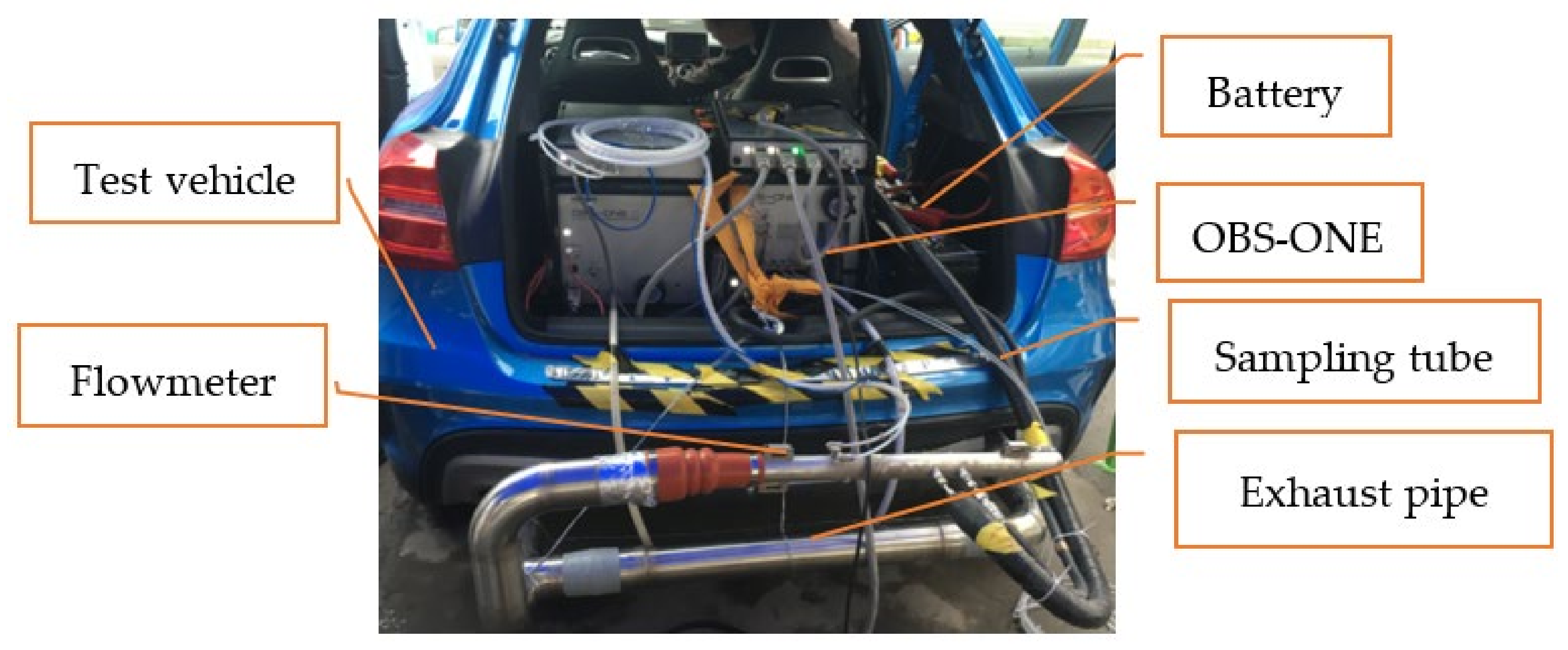
The OBS-ONE consists of three main components: a gas analysis module, a particle number (PN) analysis module, and an exhaust flow meter. There are also accessories such as a global positioning system (GPS), weather station (temperature and humidity), and OBD (on-board diagnostics) communication equipment. The gas analysis module can measure the concentration of pollutant emissions such as CO, CO2, and NOx. The particle quantity analysis module measures the quantity concentration of particulate matter. The exhaust flow meter measures the real-time flow rate of the exhaust. The GPS and weather station provide information on the speed and altitude of the test vehicle, air temperature, and humidity. The installation of PEMS equipment on a vehicle under testing is shown in Figure 1.
The OBS-ONE system requires a DC power supply of 22–28 V. Non-dispersive infra-red (NDIR) is used to determine CO and CO2 concentrations. Chemiluminescence detection (CLD) is used to determine CO2 concentration. A condensation particle counter (CPC) is used to measure PN. Table 1 summarizes the measurement principle, the analyzer range and specifications of zero gas and range gas, and the measurement error.
Table 2 shows the environmental conditions for the use of the OBS-ONE system. The specified environmental conditions are required to ensure the stable operation of the measurement equipment and measurement accuracy [36].
Figure 2 shows the schematic diagram of the OBS-ONE installation on a test vehicle before the start of the test. All test vehicles are China VI standard gasoline vehicles. The vehicles are under good maintenance. Table 3 shows the main characteristics of the test vehicles. All the vehicles tested used gasoline.
Before the RDE test, the PEMS should be warmed up. Then, the leaks should be checked and calibrated. The zero and span gas are used to calibrate the gas analyzer.
The test equipment records data before the engine starts for the first time, and the equipment records the pollutant concentration, vehicle position, and environmental conditions without interruption during the whole process [37].
The vehicle should be driven under the specified test conditions meeting the requirements of Table 4. The vehicle should be stopped after completion of the record test. To ensure data accuracy, the gas analyzer should be reinspected after stopping data recording.
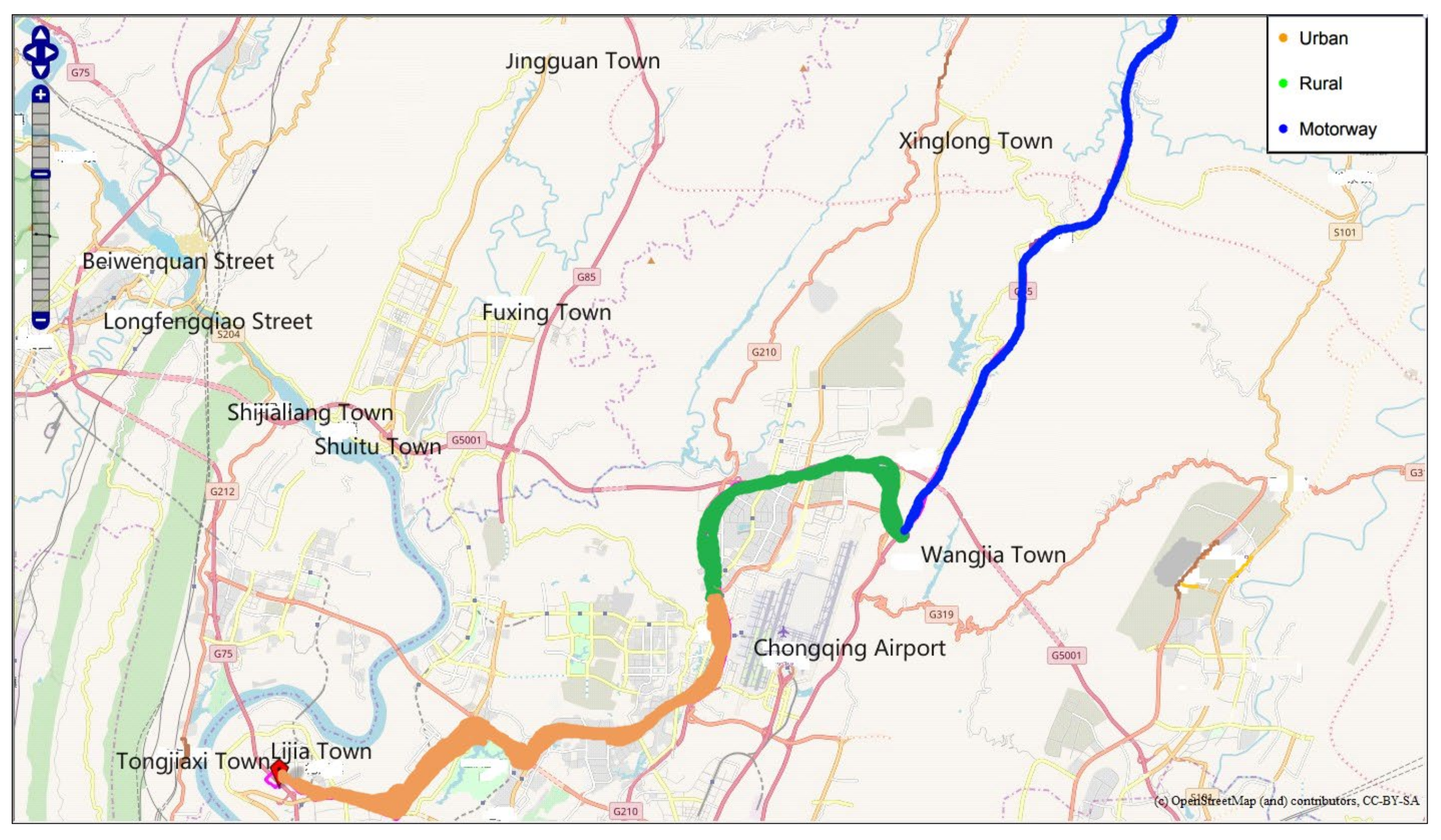
The test route is located in Chongqing, China. The total length of the route is around 79.1 km (27.8 km for urban driving; 25.7 km for rural driving; 27.2 km for motorway driving). The maximum altitude and minimum altitude are 400 m and 168 m, respectively. A map of the route is shown in Figure 3.

2.2. Experimental Data Processing

Due to the influence of the exhaust flow rate, temperature, and pressure, as well as the length of sampling pipeline, the time sequences of sample gas entering the analyzers are different, and response times of the analyzers are also different. There are timing inconsistencies between various pollutant concentration parameters recorded in the test and engine speed and vehicle speed values (which can be read via the GPS or OBD interface), so it is necessary to perform time alignment on transient data to obtain various parameters generated at the exact moment and perform pollutant mass emission calculation based on the aligned flow and concentration data. In this study, the PEMS equipment has an automatic time series correction function, and the raw data of transient mass emissions of each pollutant are the result of the correction, which can be directly used for further analysis and processing.
After the time sequence calibration, the invalid data should be eliminated, including the data generated during the PEMS equipment inspection, zero-point drift verification, and cold starting, i.e., when the coolant reaches 70 °C after engine ignition or when the coolant temperature changes less than 2 °C within 5 min.
The instantaneous pollutant emission rate m C O 2 (g/s) for gaseous pollutants could be calculated as follows:
m C O 2 = ρ C O 2 × C C O 2 × q × 10 3
In Formula (1), ρ   C O 2 (kg/m3) represents the density of CO2; C C O 2 (ppm) represents the concentration of CO2 measured using the gaseous module; q (m3/s) represents the exhaust flow rate measured using the flow meter.
The vehicle-specific power (VSP) equation is typically defined as the instantaneous power per unit vehicle mass and used to characterize the rates of emission from light-duty passenger vehicles in a real driving cycle test. The general form of VSP can be expressed by Jimenez-Palacios, 1999 [38].
                                        V S P = 1 m F a + F r + F g + F a c c v
F a = 1 2 ρ C D A v 2 , F a c c = m a
where VSP is the vehicle-specific power (kW/ton), F a   represents the aerodynamic drag force (N), m represents the vehicle mass (ton), ρ represents the air density (kg/m3), C D   represents the aerodynamic drag coefficient, A represents the vehicle frontal area (m2), v represents the instantaneous vehicle speed (m/s), F r   represents the rolling resistance (N), F g   represents the road grade resistance (N), Facc represents the inertia force (N), and a is the acceleration velocity of vehicle (m/s2), respectively.

3. Results and Discussion

3.1. Vehicle Acceleration and Acceleration Distribution

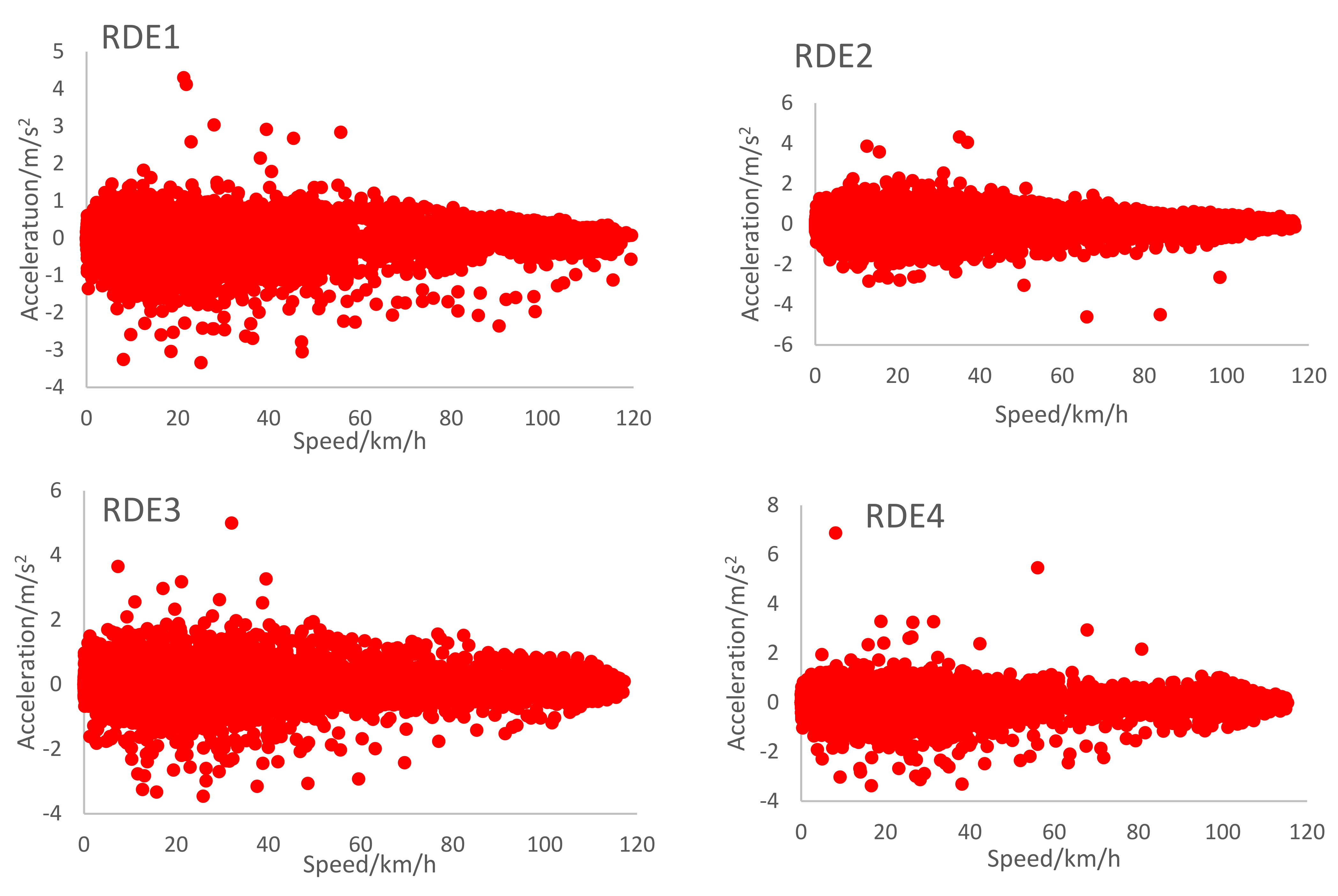
Figure 4 presents the acceleration distribution in terms of velocity for the test cycles. Compared to the other three cycles, RDE1 obtains a more concentrated distribution, with the acceleration varying from −2.5 m/s2 to 2.5 m/s2. The acceleration for RDE2 varies from around −2 m/s2 to 2 m/s2. Four RDE tests do not show a similar pattern to each other. For the RDE tests, compared to the laboratory cycle of WLTC (world light vehicle test cycle), one of the most significant characteristics is the larger deceleration. Many points are located in the area with a deceleration lower than −1.5 m/s2. Moreover, there are significant concentrations at three speed ranges: from 30 km/h to 50 km/h, from 70 km/h to 80 km/h, and from 100 km/h to 120 km/h. This concentration is associated with the speed limits of the test route (around 60 km/h for the urban part, around 90 km/h for the rural part, and around 120 km/h for the motorway) and the tendency for the coordination of speed between drivers to maintain a uniform running speed [33,34,35].
RDE experiments have more influencing factors, and too many input parameters lead to low characterization accuracy [36].

3.2. CO2 Emission Factor

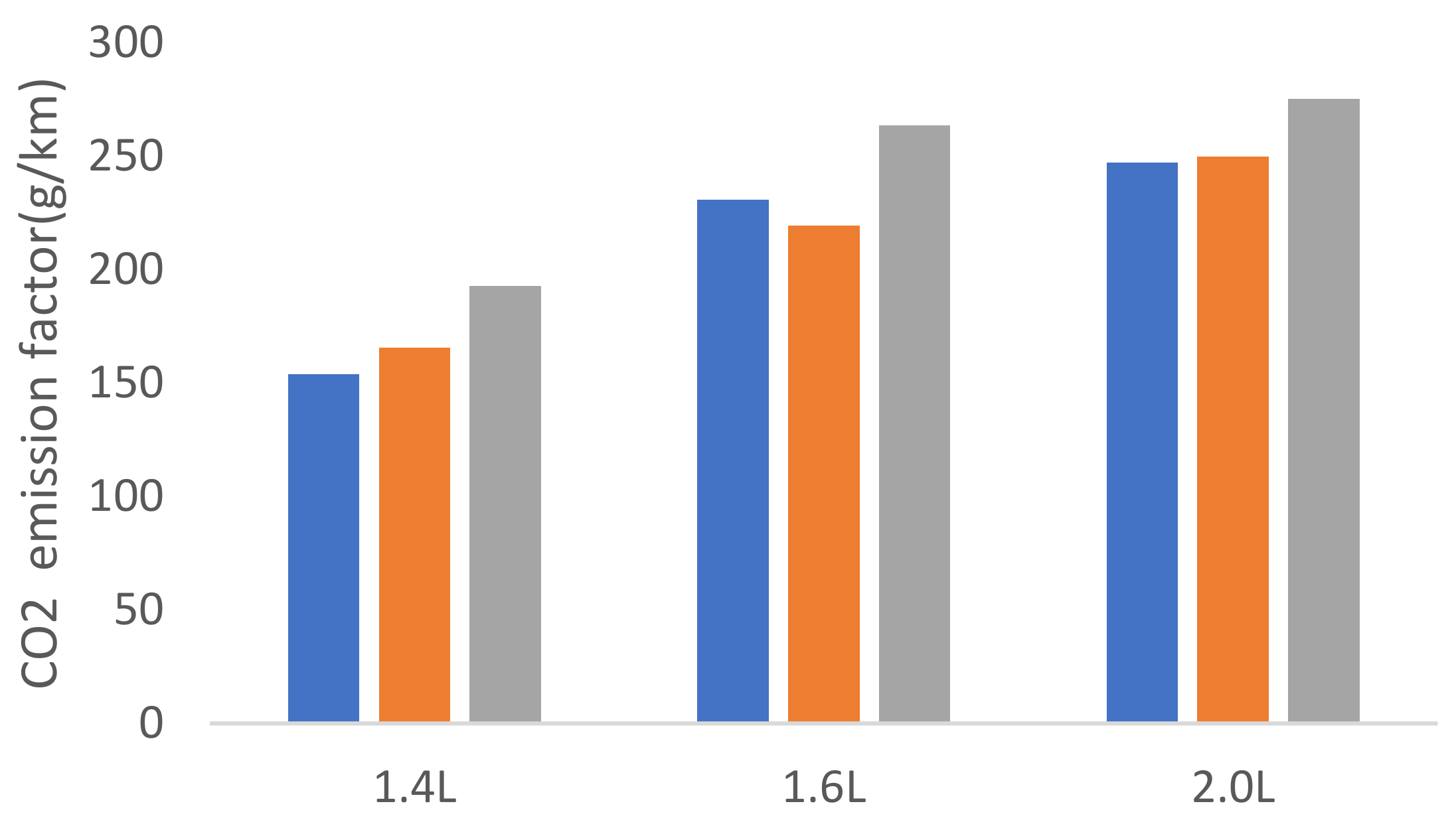
Figure 5 shows the CO2 emission factor. Each column represents the CO2 emission factor of each test vehicle, respectively. The CO2 emission factor can be calculated for different displacement vehicles under different RDE conditions, and it can be obtained that the CO2 emission factor increases with the increase in vehicle displacement.
Figure 6 shows the CO2 emission factors for different displacement vehicles. The CO2 emission factors of the vehicles increased to different levels with an increase in speed. In urban, suburban, and high-speed conditions, the CO2 emission factor increases with the increase in the average speed for different displacement models, and the CO2 emission factor is 24% higher for the 1.4 L model, 14% higher for the 1.6 L model, and 11% higher for the 2.0 L model in high-speed conditions compared with urban conditions. This indicates that the smaller displacement models emit more CO2 at highway speeds than in the city, but this trend decreases as the displacement increases. It is mainly due to the fact that the instantaneous CO2 mass emission spike occurs at high-engine-load periods, with the engine speed reaching around 5000 r/min and the instantaneous mass emission rate potentially reaching around 16 g/s. With the engine speed reaching 5000 r/min in the small displacement model, there is less time for the fuel droplets to mix and evaporate, resulting in locally rich regions and incomplete combustion. CO2 is formed during hydrocarbon combustion in these locally rich regions, resulting in high CO2 emission.
Figure 7 shows the CO2 emission rate of the tested vehicles. The CO2 emission rate of 2.0 L vehicles is higher than other models, and the maximum emission rate is more than 14 g/s, and the average emission rate is higher under urban conditions. Further, 1.4 L vehicles have a CO2 emission rate basically less than 12 g/s, and the maximum emission rate of all three models is more than 16 g/s.

3.3. CO2 Emission Based on VSP

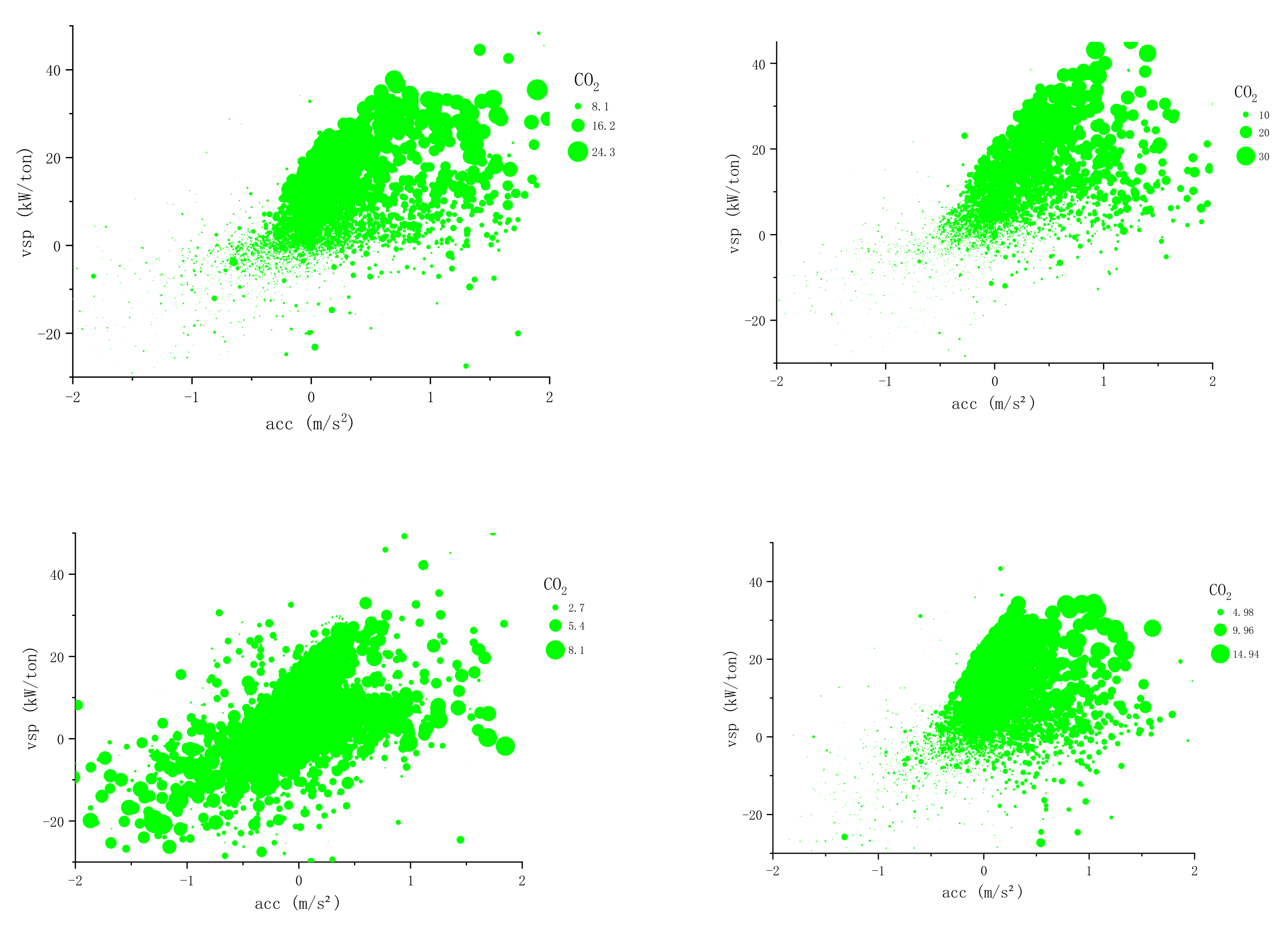
From Figure 8. It can be obtained that the CO2 emission frequencies of light-duty vehicles under an RDE cycle without altitude are mainly concentrated in the VSP range of −9 to 18 and the acceleration range of −1 to 0.8, among which the highest CO2 frequencies are found in operating conditions with a VSP range of −20 to 20 and acceleration range of −0.6 to 0.4. Comparing the distribution of CO2 emission frequency with and without altitude RDE cycles, it can be obtained that the VSP and acceleration range of the concentrated distribution of CO2 emission frequency are similar, but it is obvious that the distribution of CO2 emission frequency based on VSP is wider and more dispersed under the RDE cycle with altitude for light vehicles, so considering altitude has an obvious influence on acceleration and VSP distribution. To further investigate the relationship between VSP and carbon emissions, bubble diagrams of CO2 emissions were drawn for each vehicle under different cycle operating conditions.
The size of the bubbles in the graph represents the CO2 emission, the green bubble represents the CO2 emission rate when VSP is less than or equal to 20, and the blue bubble represents the CO2 emission rate when VSP is greater than 20. According to the plotted results, it is found that the transient emission rate of CO2 shows a regular increasing trend with the size of the power demand and specific power, while the driving acceleration has no obvious correlation. In addition, when VSP and acceleration approach zero, except for the altitude RDE cycle condition, the rest of the upper bubble images appear as short horizontal lines. According to the VSP calculation formula, it can be obtained that the vehicle speed and acceleration are zero at this time, and the vehicle is idle. The CO2 emissions of the vehicle when idling are very small. The distribution of CO2 emission rate in the RDE condition is greater when VSP is greater than 20, which indicates that the CO2 emission rate is high under intense driving conditions in the ultra-high-speed section of the vehicle. The acceleration range corresponding to the CO2 concentration emission rate in the RDE condition is similar at −0.6~1.5 m/s2.
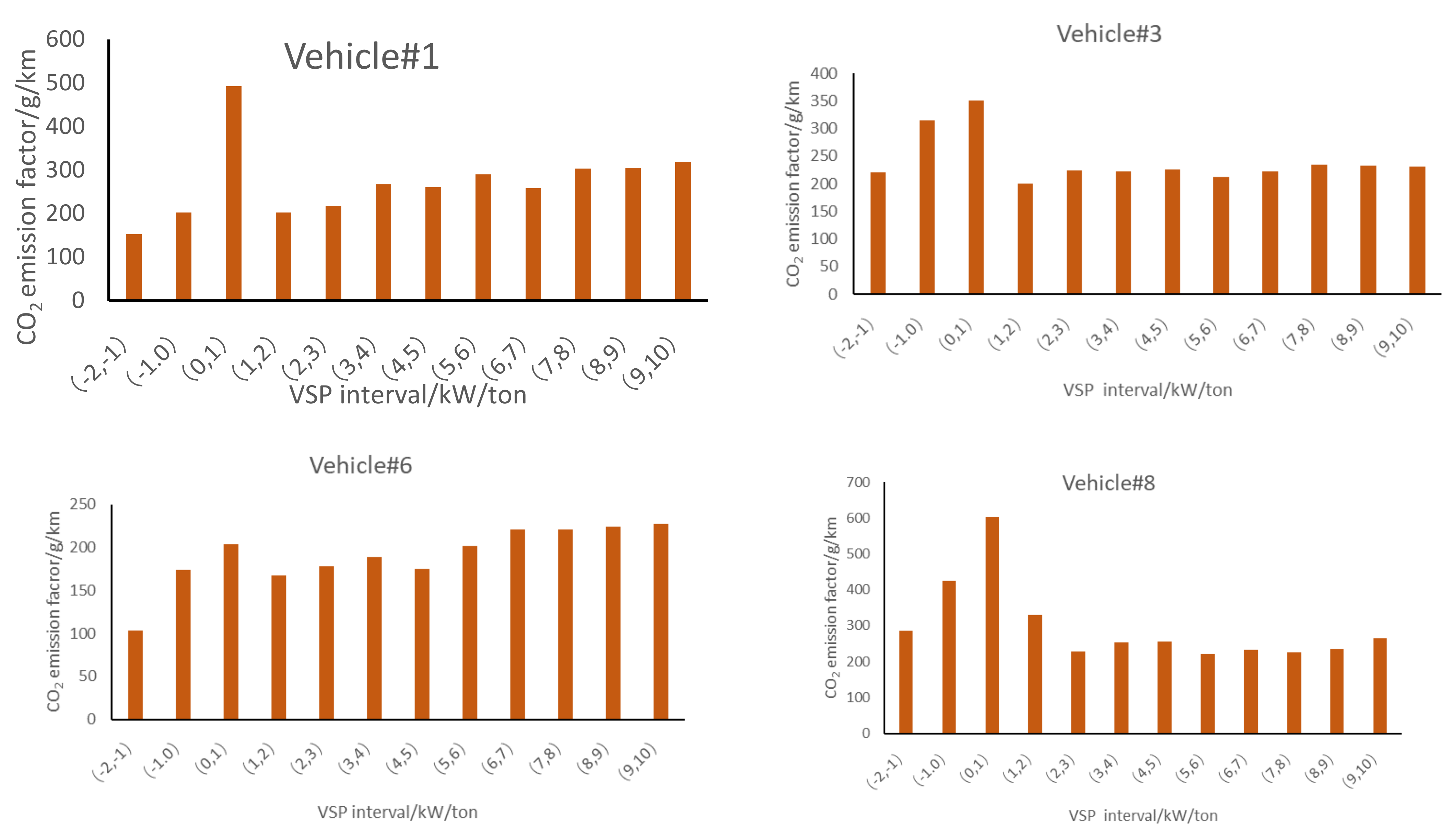
Figure 9 shows the overall CO2 emission with respect to the vehicle-specific power for the real driving of different vehicles. In particular, the lower curve showing the distribution of time for each vehicle-specific power depicts the whole range with respect to each vehicle-specific power. As shown in this figure, the amount of CO2 emissions can be reliant on the time period of vehicle-specific power. The CO2 emission mainly exhibits peaks in the positive vehicle-specific power range. The amounts of total CO2 emission in the positive region and the negative region make up 82~89% and 11~18% of the overall CO2 emission during the entire driving period, respectively.

4. Conclusions

Ten light-duty passenger vehicles with different technical parameters were successfully tested under real-world driving conditions. The CO2 emissions factor and emissions rate of each vehicle were analyzed.
The CO2 emission factor varies considerably from displacement size, up to 281 g/km, and the factor is 1.5 times higher for larger displacement vehicles than for smaller displacement vehicles.
The amounts of total CO2 emission in the positive region and the negative region make up 82~89% and 11~18% of the overall CO2 emission during the entire RDE driving period. Therefore, the control of CO2 emissions from actual roads should primarily be controlled in the positive region.
The same vehicle has a wide range of CO2 emission factors at different VSP intervals. Different RDE test conditions can lead to large differences in CO2 emissions even under the same road RDE test cycle, and the speed and acceleration distribution of different vehicles still vary greatly. So, without considering other influencing factors, the CO2 emission from the RDE test alone cannot be used to evaluate the CO2 emission level of the vehicle and must be combined with laboratory working conditions, such as WLTC and CLTC cycles.
The CO2 versus VSP histogram plot of the vehicle shows that the CO2 emission rate of the light-duty vehicle is between a certain range of values at the same VSP. This indicates that there are other factors that influence the emission rate of light-duty vehicles at the same VSP: for example, whether the air conditioner is on or not, whether there are harsh working conditions or not, etc.
Even though the VSP intervals are the same, the CO2 emission rates of light-duty vehicles vary greatly due to different operating speeds. In general, the CO2 emission rate increases to different degrees with the increase in vehicle VSP in the same speed band, among which the CO2 emission rate shows an obvious linear increase.

Author Contributions

Conceptualization, H.X. and M.L.; methodology, J.T.; software, Y.L.; validation, Y.G. and L.H.; formal analysis, X.W. All authors have read and agreed to the published version of the manuscript.

Funding

This research is supported by the China Automotive Engineering Research Institute Corporation Innovation Projects Program and National Key Research & Development Project of China [2022YFC3701802].

Conflicts of Interest

The authors declare no conflict of interest.

References

  1. Ministry of Ecology and Environment of the People’s Republic of China. China Mobile Source Environmental Management Annual Report. 2021. Available online: http://www.gov.cn/xinwen/2021-09/11/content_5636764.htm (accessed on 2 April 2023).
  2. Huang, Z.; Tang, D. Estimation of Vehicle Toxic Air Pollutant Emissions in China. Res. Environ. Sci. 2008, 21, 166–170. [Google Scholar] [CrossRef]
  3. Li, T.; Chen, X.; Yan, Z. Comparison of fine particles emissions of light-duty gasoline vehicles from chassis dynamometer tests and on-road measurements. Atmos. Environ. 2013, 68, 82–91. [Google Scholar] [CrossRef]
  4. Weiss, M.; Bonnel, P.; Hummel, R.; Provenza, A.; Manfredi, U. On-Road Emissions of Light-Duty Vehicles in Europe. Environ. Sci. Technol. 2011, 45, 8575–8581. [Google Scholar] [CrossRef] [PubMed]
  5. Weiss, M.; Bonnel, P.; Kühlwein, J.; Provenza, A.; Lambrecht, U.; Alessandrini, S.; Carriero, M.; Colombo, R.; Forni, F.; Lanappe, G. Will Euro 6 reduce the CO2 emissions of new diesel cars?–Insights from on-road tests with Portable Emissions Measurement Systems (PEMS). Atmos. Environ. 2012, 62, 657–665. [Google Scholar] [CrossRef]
  6. Carslaw, D.C.; Beevers, S.D.; Tate, J.E.; Westmoreland, E.J.; Williams, M.L. Recent evidence concerning higher CO2 emissions from passenger cars and light duty vehicles. Atmos. Environ. 2011, 45, 7053–7063. [Google Scholar] [CrossRef]
  7. Vojtisek-Lom, M.; Fenkl, M.; Dufek, M.; Mareš, J. Off-cycle, real-world emissions of modern light duty diesel vehicles. SAE Tech. Pap. 2009, 148, 22. [Google Scholar] [CrossRef]
  8. Lee, T.; Park, J.; Kwon, S.; Lee, J.; Kim, J. Variability in operation-based CO2 emission factors with different test routes, and its effects on the real-driving emissions of light diesel vehicles. Sci. Total Environ. 2013, 461, 377–385. [Google Scholar] [CrossRef] [PubMed]
  9. Pathak, S.K.; Sood, V.; Singh, Y.; Channiwala, S.A. Real world vehicle emissions: Their correlation with driving parameters. Transp. Res. D Tr. E 2016, 44, 157–176. [Google Scholar] [CrossRef]
  10. Ministry of Ecology and Environment of the People’s Republic of China. Limits and Measurement Methods for Emissions from Light-Duty Vehicles (China VI). 2020. Available online: https://www.mee.gov.cn/ywgz/fgbz/bz/bzwb/dqhjbh/dqydywrwpfbz/201612/t20161223_369476.shtml (accessed on 1 July 2020).
  11. European Commission. Testing of Emissions from Cars. 2018. Available online: https://europa.eu/rapid/press-release_MEMO-18-3646_en.html (accessed on 4 May 2018).
  12. Song, B.; Ge, Y.; Yin, H.; Yang, Z.; Wang, X.; Tan, J. A Study on the Effects of Driving Dynamics Parameters on the Results of RDE Test. Automot. Eng. 2018, 40, 389–395, 442. [Google Scholar] [CrossRef]
  13. Mei, H.; Wang, L.; Wang, M.; Zhu, R.; Wang, Y.; Li, Y.; Zhang, R.; Wang, B.; Bao, X. Characterization of Exhaust CO, HC and CO2 Emissions from Light-Duty Vehicles under Real Driving Conditions. Atmosphere 2021, 12, 1125. [Google Scholar] [CrossRef]
  14. Ge, Y.; Wang, Y.; Dong, H.; Song, B.; Yin, H.; Li, Z.; Yang, Z. The Adaptability of the RDE Window Method for Actual China Road. Trans. Beijing Inst. Technol. 2020, 40, 924–928. [Google Scholar] [CrossRef]
  15. Ge, Y.; Ding, Y.; Yin, H. Research status of real driving emission measurement system for vehicles. J. Automot. Saf. Energy 2017, 8, 111–121. [Google Scholar] [CrossRef]
  16. Ge, Y.; Wang, A.; Wang, M.; Ding, Y.; Tan, J.; Zhu, Y. Application of portable emission measurement system(PEMS)on the emission measurements of urban vehicles on-road. J. Automot. Saf. Energy 2010, 1, 141–145. [Google Scholar] [CrossRef]
  17. Guo, J.; Ge, Y.; Tan, J.; Zhang, X.; Yu, L.; Fu, M. A Research on the Real World Emission Characteristics of State-V Buses. Automot. Eng. 2015, 37, 120–124. [Google Scholar] [CrossRef]
  18. Luo, J.; Wen, Y.; Yang, Z.; Zhu, Q.; Pan, P. Comparative Study of Real Driving and Bench Test Cycle Emission for China-Ⅵ Light-Duty Vehicles. Veh. Engine 2019, 6, 64–70. [Google Scholar]
  19. Yang, Z.; Fu, B.; Yin, H.; Tan, J.; Zhou, X.; Ge, Y. A Research on the Real Driving Emission Characteristics of Light-duty Diesel Vehicles. Automot. Eng. 2017, 39, 497–502. [Google Scholar] [CrossRef]
  20. Fu, B.; Yang, Z.; Yin, H.; Zhou, X.; Tan, J.; Ge, Y. A Research on the Real Driving Emission Characteristics of Light-duty gasoline Vehicles. Automot. Eng. 2017, 39, 376–380. [Google Scholar] [CrossRef]
  21. Wang, H.Y.; Ji, C.W.; Shi, C.; Ge, Y.S.; Meng, H.; Yang, J.X.; Chang, K.; Wang, S.F. Comparison and evaluation of advanced machine learning methods for performance and emissions Characterization of a gasoline Wankel rotary engine. Energy 2022, 248, 123611. [Google Scholar] [CrossRef]
  22. Wang, H.Y.; Ji, C.W.; Shi, C.; Ge, Y.S.; Wang, S.F.; Yang, J.X. Development of cyclic variation Characterization model of the gasoline and n-butanol rotary engines with hydrogen enrichment. Fuel 2021, 299, 120891. [Google Scholar] [CrossRef]
  23. Wang, H.; Ji, C.; Yang, J.; Wang, S.; Ge, Y. Towards a comprehensive optimization of the intake characteristics for side ported Wankel rotary engines by coupling machine learning with genetic algorithm. Energy 2022, 261, 125334. [Google Scholar] [CrossRef]
  24. Zhang, R.; Wang, Y.; Pang, Y.; Zhang, B.; Wei, Y.; Wang, M.; Zhu, R. A Deep Learning Micro-Scale Model to Estimate the CO2 Emissions from Light-Duty Diesel Trucks Based on Real-World Driving. Atmosphere 2022, 13, 1466. [Google Scholar] [CrossRef]
  25. Jaikumar, R.; Nagendra, S.M.S.; Sivanandan, R. Modeling of real time exhaust emissions of passenger cars under heterogeneous traffic conditions. Atmos. Pollut. Res. 2017, 8, 80–88. [Google Scholar] [CrossRef]
  26. Hien, N.L.H.; Kor, A. Analysis and Characterization Model of Fuel Consumption and Carbon Dioxide Emissions of Light-Duty Vehicles. Appl. Sci. 2022, 12, 803. [Google Scholar] [CrossRef]
  27. Seo, J.; Yun, B.; Park, J.; Park, J.; Shin, M.; Park, S. Characterization of instantaneous real-world emissions from diesel light-duty vehicles based on an integrated artificial Principal component analysis method and vehicle dynamics model. Sci. Total Environ. 2021, 786, 147359. [Google Scholar] [CrossRef] [PubMed]
  28. Seo, J.; Yun, B.; Kim, J.; Shin, M.; Park, S. Development of a cold-start emission model for diesel vehicles using an artificial Principal component analysis method trained with real-world driving data. Sci. Total Environ. 2022, 806, 151347. [Google Scholar] [CrossRef] [PubMed]
  29. Bielaczyc, P.; Woodburn, J.; Szczotka, A. Exhaust Emissions of Gaseous and Solid Pollutants Measured over the NEDC, FTP-75 and WLTC Chassis Dynamometer Driving Cycles; SAE Technical Paper: Warrendale, PA, USA, 2016. [Google Scholar] [CrossRef]
  30. Zhou, B.; Tan, D.; Wei, D.; ShiVSP, S.; Machacon, H. Characterization of Emissions from Internal Combustion Engine Using a Principal component analysis method. Trans. Csice 2001, 19, 361. [Google Scholar] [CrossRef]
  31. Duarte, G.O.; Gonçalves, G.A.; Farias, T.L. Analysis of fuel consumption and pollutant emissions of regulated and alternative driving cycles based on real-world measurements. Transp. Res. Part D Transp. Environ. 2016, 44, 43–54. [Google Scholar] [CrossRef]
  32. Gallus, J.; Kirchner, U.; Vogt, R.; Benter, T. Impact of driving style and road grade on gaseous exhaust emissions of passenger vehicles measured by a Portable Emission Measurement System (PEMS). Transp. Res. Part D Transp. Environ. 2017, 52, 215–226. [Google Scholar] [CrossRef]
  33. Wang, Y.; Hao, C.; Ge, Y. Fuel consumption and emission performance from light-duty conventional/ hybrid-electric vehicles over different cycles and real driving tests. Fuel 2020, 278, 118340. [Google Scholar] [CrossRef]
  34. Huang, Y.; Surawski, N.C.; Organ, B.; Zhou, J.L.; Tang, O.H.H.; Chan, E.F.C. Fuel consumption and emissions performance under real driving: Comparison between hybrid and conventional vehicles. Sci. Total Environ. 2019, 659, 275–282. [Google Scholar] [CrossRef]
  35. Pavlovic, J.; Marotta, A.; Ciuffo, B. CO2 emissions and energy demands of vehicles tested under the NEDC and the new WLTP type approval test procedures. Appl. Energy 2016, 177, 661–670. [Google Scholar] [CrossRef]
  36. Li, H.; Butts, K.; Zaseck, K.; Liao-McPherson, D.; Kolmanovsky, I. Emissions Modeling of a Light-Duty Diesel Engine for Model-Based Control Design Using Multi-Layer Perceptron Principal Component Analysis Methods; SAE Technical Paper: Warrendale, PA, USA, 2017. [Google Scholar] [CrossRef]
  37. McCaffery, C.; Zhu, H.; Li, C.; Durbin, T.D.; Johnson, K.C.; Jung, H.; Brezny, R.; Geller, M.; Karavalakis, G. On-road gaseous and particulate emissions from GDI vehicles with and without gasoline particulate filters (GPFs) using portable emissions measurement systems (PEMS). Sci. Total Environ. 2020, 710, 136366. [Google Scholar] [CrossRef]
  38. Jimenez-Palacios, J. Understanding and Quantifying Motor Vehicle Emissions and Vehicle Specific Power with TILDAS Remote Sensing; MIT: Cambridge, MA, USA, 1999. [Google Scholar]
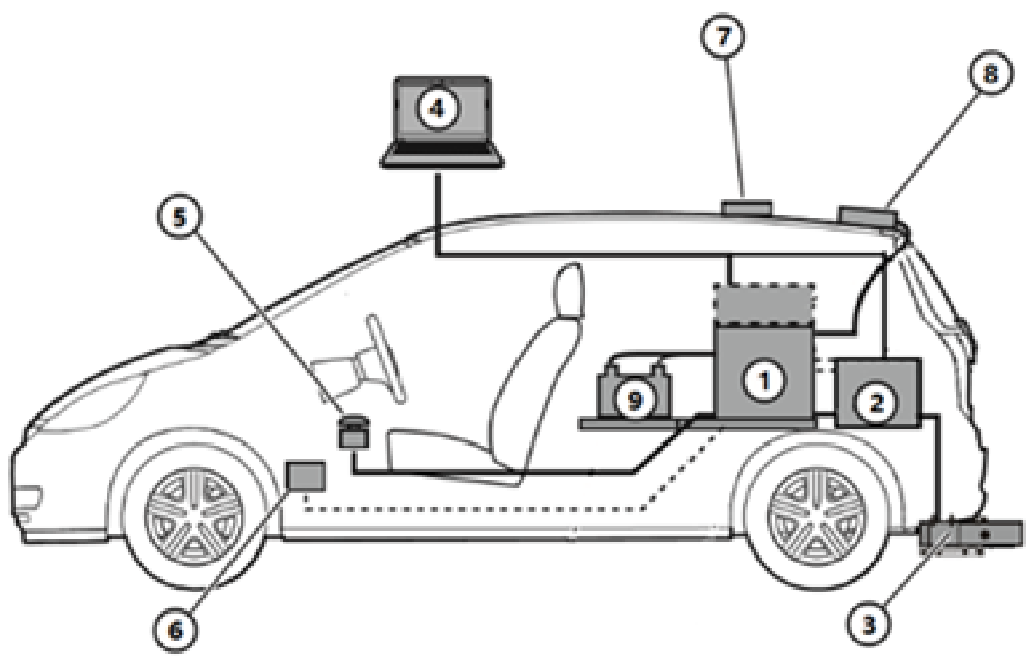
Figure 1. Schematic diagram of PEMS installation. ① PEMS analysis module. ② PN counting module. ③ Exhaust gas flow meter. ④ Control computer. ⑤ Emergency stop switch. ⑥ OBD communication connection. ⑦ GPS. ⑧ Weather station. ⑨ External battery.
Atmosphere 14 01467 g001
Figure 2. PEMS equipment on the vehicle.
Atmosphere 14 01467 g002
Figure 3. A tracing of the test route.
Atmosphere 14 01467 g003
Figure 4. Acceleration vs. velocity for test cycles.
Atmosphere 14 01467 g004
Figure 5. CO2 emission factor.
Atmosphere 14 01467 g005
Figure 6. CO2 emission factors for different displacement vehicles.
Atmosphere 14 01467 g006
Figure 7. CO2 emission rate for different displacement vehicles.
Atmosphere 14 01467 g007
Figure 8. CO2 emission frequencies of light-duty vehicles under RDE cycle.
Atmosphere 14 01467 g008
Figure 9. CO2 emission factors based on VSP interval.
Atmosphere 14 01467 g009
Table 1. OBS-ONE measurement system technical specifications.
Gaseous PollutantsMeasurement PrincipleMeasurement RangeZero GasMeasuring Distance GasZero Gas/Measurement Distance Gas PressureZero Gas/Measurement Distance Gas FlowMeasurement Error
CONDIR10 vol%Synthetic airgas mixture (CO + CO2 + C3H8 +
NO/N2) and NO2
100 kPa ± 10 kPa2.5~4.0 L/min≤0.1 ppm
CO2NDIR20 vol%
CO2CLD1600 ppm
PNCPC ≤1% F.S
Table 2. Environmental conditions for the use of OBS-ONE.
ProjectsConditions
Temperature0~40 °C
HumidityRelative humidity below 80%
Ambient NOx concentrationAmbient NOx concentration less than 1 ppm
PowerUse a dedicated power supply without any voltage/swing oscillations
VentilationThe exhaust of the system should be safely discharged to the outside environment
Maintenance spaceAmple maintenance space outside the system
Wind and RainWaterproof Indoor
Electromagnetic fieldThe system must not be placed in a strong magnetic field
Maximum payloadTest vehicle load must be greater than the test system mass (including batteries and gas cylinders)
Table 3. Main characteristics of the test vehicles.
Test IDEngine TypeDisplacement/LPower/kWTorque/NmAftertreatmentMileage/kmMass/kg
1GDI2.0167380TWC + GPF41672145
2GDI2.0167380TWC + GPF82852187
3GDI2.0171380TWC + GPF9552007
4GDI1.4118255TWC + GPF2801390
5PFI1.690152TWC + GPF30581715
6GDI1.6145275TWC + GPF35541610
7GDI1.6145275TWC + GPF30281610
8GDI1.6145275TWC + GPF30781580
9PFI1.580141TWC + GPF55741335
10PFI1.5115207TWC36101610
Table 4. RDE test conditions parameters.
ProjectsSpeed/(km·h−1)Mileage/kmOther Requirements
Urban≤60≥16The actual speed of less than 1 km/h time accounted for 6–30%
Suburban60~90≥16Suburban driving is allowed to be interrupted by urban driving
Highway90~120≥16Vehicle speed above 100 km/h should reach at least 5 min or more
Disclaimer/Publisher’s Note: The statements, opinions and data contained in all publications are solely those of the individual author(s) and contributor(s) and not of MDPI and/or the editor(s). MDPI and/or the editor(s) disclaim responsibility for any injury to people or property resulting from any ideas, methods, instructions or products referred to in the content.