Article

Particulate Matter Emission and Air Pollution Reduction by Applying Variable Systems in Tribologically Optimized Diesel Engines for Vehicles in Road Traffic

Faculty of Engineering, University of Kragujevac, Sestre Janjić 6, 34000 Kragujevac, Serbia
*
Author to whom correspondence should be addressed.
Atmosphere 2024, 15(2), 184; https://doi.org/10.3390/atmos15020184
Submission received: 28 December 2023 / Revised: 25 January 2024 / Accepted: 29 January 2024 / Published: 31 January 2024
(This article belongs to the Special Issue Engine Emissions and Air Quality Effects)

Abstract

:
Regardless of the increasingly intensive application of vehicles with electric drives, internal combustion engines are still dominant as power units of mobile systems in various sectors of the economy. In order to reduce the emission of exhaust gases and satisfy legal regulations, as a temporary solution, hybrid drives with optimized internal combustion engines and their associated systems are increasingly being used. Application of the variable compression ratio and diesel fuel injection timing, as well as the tribological optimization of parts, contribute to the reduction in fuel consumption, partly due to the reduction in mechanical losses, which, according to test results, also results in the reduction in emissions. This manuscript presents the results of diesel engine testing on a test bench in laboratory conditions at different operating modes (compression ratio, fuel injection timing, engine speed, and load), which were processed using a zero-dimensional model of the combustion process. The test results should contribute to the optimization of the combustion process from the aspect of minimal particulate matter emission. As a special contribution, the results of tribological tests of materials for strengthening the sliding surface of the aluminum alloy piston and cylinder of the internal combustion engine and air compressors, which were obtained using a tribometer, are presented. In this way, tribological optimization should also contribute to the reduction in particulate matter emissions due to the reduction in fuel consumption, and thus emissions due to the reduction in friction, as well as the recorded reduction in the wear of materials that are in sliding contact. In this way, it contributes to the reduction in harmful gases in the air.

1. Introduction

The emission of particulate matter (PM) from vehicles refers to the emission of small particles into the air that originate from the combustion of fuel or other processes in the vehicle. These PMs can be harmful to the environment and human health [1,2]. With diesel engines, the problem is that the raw combustion products in the exhaust system contain a significantly higher number of different types of particles, including soot particles. This mainly refers to fine particles whose nucleus diameters are 1–2.5 µm, the so-called PM2.5 [3,4]. These particles are very small and can be inhaled easily. When inhaled, soot particles can enter the lungs, reach the alveoli, and cause various health problems. Alveoli are tiny bubbles in the lungs that regulate the exchange of oxygen and carbon dioxide between air and blood. When particles reach the lungs, they can settle in the alveoli and interfere with the normal function of the respiratory system. This can lead to respiratory problems such as asthma, bronchitis, or even an increased risk of heart disease [5,6]. The effect of emission reduction can be evaluated through indicators [7].
The fact is that, due to increasingly strict regulations on the emission of exhaust gases, many countries and cities are introducing bans or restrictions related to diesel engines. Also, a growing number of car manufacturers are turning their attention to electric vehicles and hybrids as the future of transportation. However, this does not mean that diesel engines will disappear completely. Technology is still evolving, and manufacturers are working to optimize diesel engines to reduce emissions and increase efficiency. Also, diesel engines are still popular in some sectors, such as freight transport, where higher pulling power and operational range are required [8,9].
In the period of transition from classic to alternative and electric drives, diesel engines have a place as economical drive systems in trucks and buses with hybrid drives. In these vehicles, an electric motor and a diesel engine are combined in the drive system in order to achieve greater fuel economy and lower emissions of PM and other harmful gases. Diesel engines are mainly used in hybrid vehicles to charge the batteries of the electric motor or to provide additional power during acceleration of the vehicle. From that point of view, diesel engines are used on the open road (highways) at full load when they are the most economical, while electric drives are used in cities [10,11].
The general conclusion is that the future of diesel engine application depends on optimization and the introduction of technological innovations. To reduce PM emissions, vehicles can be equipped with emission control systems or use alternative fuels that are cleaner compared to diesel or gasoline [12].
The reduction in PM emissions from diesel engines can be achieved by so-called internal and external measures. Internal measures include the optimization of the combustion process in order to reduce raw emissions in the cylinder, while external measures include the application of modern technologies for subsequent catalytic processing of combustion products in the exhaust system.
When optimizing the combustion process, it should be kept in mind that technologies that contribute to the reduction in PM emissions increase the emission of nitrogen oxides (NOx). In the case of diesel engines, this is shown as a compromise between PM and NOx emissions or PM-NOx trade-off [13,14].
From the aspect of PM and soot emission reduction, a significant contribution was made by the application of modern technologies for diesel fuel injection systems [15,16].
Modern diesel engines are equipped with systems for electronically controlled direct injection of fuel into the cylinder under high pressure by means of injectors with multiple holes of extremely small diameter. In this way, more optimal conditions are created for a better formation of the mixture of diesel fuel and air, the combustion is more complete, and the emission of PM and fuel consumption are lower. Thanks to the application of an electronically controlled fuel injector made of piezo crystals, etc., the injection is realized in several stages, such as pilot, main, and late fuel injection. Pilot fuel injection enables the pre-mixing of fuel and air, while subsequent injection contributes to the combustion of unburned combustion products, which reduces emissions and fuel consumption. A split diesel injection strategy with pilot fuel injection enables the pre-mixing of fuel and air, while subsequent injection contributes to the combustion of unburned combustion products, which reduces emissions and fuel consumption [16,17].
The intake air swirl is a technology that makes it possible to achieve an optimal PM-NOx trade-off. The shape of the intake valve port and the combustion chamber, specifically in the piston head, etc., causes air to swirl. For example, in passenger vehicles at low loads during city driving, a more intense air swirl can contribute to a reduction in PM emissions specifically because of better mixture formation [18].
High-pressure fuel injection in combination with air swirl contributes to the reduction in PM emissions, thereby achieving the optimal trade-off between PM and NOx emissions, and, in the case of using exhaust gas recirculation (EGR), to lowering NOx emissions [19,20].
Variable systems on diesel engines are necessary due to simultaneous adaptation for working with fuel of different quality or for working with alternative fuels. From that aspect, by applying a variable compression ratio (VCR), diesel engines have the possibility of multi-fuel, which is significant for special vehicles, especially in environments with limited availability of different types of fuel [21].
The application of alternative fuels is increasingly relevant in diesel engines as an alternative to conventional diesel fuel in order to reduce emissions and save resources. Some of the most common forms of alternative fuels in diesel engines are biodiesel, synthetic diesel fuels, and compressed natural gas (CNG) [22].
Biodiesel is an alternative fuel that is produced from renewable sources such as vegetable oils or waste oils. It can be used as a replacement for conventional diesel fuel in diesel engines, with the application of additives or ethanol port injection and appropriate engine modifications with accompanying variable systems [23,24].
Synthetic diesel fuels are fuels produced from hydrocarbons obtained from natural gas, coal, or biomass. They have similar characteristics to conventional diesel fuel but can be produced in a more sustainable and ecological way [23].
Compressed natural gas (CNG) consists mainly of methane and can be used in purpose-designed dual-fuel diesel engines that have been converted to use CNG and run on both fuels simultaneously. Dual-fuel systems for diesel engines are very practical when used for the conversion of existing vehicle fleets to alternative fuels as an initial phase until the complete transition to full gas or another vehicle drive. This especially applies to vehicles in the city for the transportation of passengers by buses, utility trucks, etc. [25].
In both cases, whether it is classic diesel or dual-fuel diesel engines with an optimized combustion process, in order to reduce emissions and meet emission standards, it is additionally necessary to apply catalytic processing of raw combustion products. In vehicles with diesel engines, the catalytic conversion is realized by using oxidation catalysts that have been upgraded over time, with catalysts for NOx reduction, which have been modernized by using catalysts that work on the principle of selective catalytic reduction (SCR), as well as with catalytic PM filters with regeneration. In this way, the problems resulting from the collection of PM in the catalysts were solved because, through regeneration, i.e., combustion in the presence of oxygen or nitrogen dioxide, which is supported by the increased temperature of the exhaust gases, the PM is transformed into gaseous carbon dioxide (CO2) [26,27].
In the case of vehicles powered by natural gas, upgraded catalysts are used, which are similar to those on gasoline engines. In that case, raw exhaust gases are passed through a large number of channels made of ceramic materials, which are coated with noble metals that act as catalysts [28]. For coatings, palladium is most often used, which reacts with exhaust gases, turning the products into water, nitrogen, and CO2. With dual-fuel engines powered by diesel fuel and natural gas, the emissions of carbon monoxide (CO) and hydrocarbons (HC) are also problematic, similar to gasoline engines, which are solved by using a catalyst, as well as the emission of methane. Methane (CH4) is one of the gases that cause the greenhouse effect (it has 20 times more potential compared to CO2). The incomplete combustion of CH4 produces formaldehyde, which is classified as a carcinogenic substance. On the other hand, CH4 cannot be fully treated in the exhaust gases using noble metal catalysts because formaldehyde and other combustion products bind to the catalyst material more easily than methane and quickly saturate and block the surface. In smaller internal combustion (IC) engines that use natural gas as fuel, the combustion process takes place with a stoichiometric mixture composition. In that case, the problematic emission of CO, HC, CH4, and NOx is solved by using three-way catalysts (TWC). However, in IC engines with a larger capacity, the combustion process of natural gas is realized with a lean mixture of fuel and air in order to reduce the maximum temperature and, thus, the NOx emissions. A lean mixture contributes to the reduction in fuel consumption and, thus, the raw emissions of combustion products. A lean mixture in IC engines contributes to the reduction in fuel consumption and, thus, the raw emissions of combustion products. Compared to running exclusively on diesel fuel, the application of natural gas reduces CO2 emissions by approximately 35% [29,30].
Particulate matter emission can be reduced successfully by natural gas application as well as through the above-listed technologies. In dual-fuel diesel and dedicated natural gas IC engines, raw PM emission is lower than emission in diesel engines after catalytic treatment. The combustion process in dedicated gas engines does not produce PM emissions, where the only source of PM emission is the oil presence in combustion chamber [30].
From that aspect, the tribological optimization of the assembly, piston, piston rings, and cylinder liner in IC engines can contribute to the reduction in oil consumption from the lubrication system and, thus, PM emissions. The tribological optimization of this assembly contributes to the reduction in friction and wear, i.e., mechanical losses, which directly contributes to the reduction in fuel consumption and emissions [31,32].
As one of the possible solutions, due to its impact on reducing mass and emissions, aluminum is increasingly used in IC engines. The most common application of aluminum in IC engines is for making engine blocks, pistons, and engine heads. Also, aluminum alloys have good corrosion resistance and transfer heat more efficiently due to their higher specific thermal conductivity compared to steel alloys, which is important for maintaining optimal temperature [33]. However, it should be noted that for the production of parts of the piston and cylinder liner, connecting rod, and bearings, steels are often used due to their greater durability under high temperatures and pressures [34,35]. However, due to the targeted weight reduction, different technologies are applied to strengthen the sliding surface of the cylinder and pistons made of aluminum alloy [36]. Honing technologies, textures, and surface coatings with tribological materials, which have greater strength and resistance to friction and wear compared to aluminum alloys, are most often used [37,38].
At the same time, the optimization of peripheral devices and equipment on the IC engines, such as reciprocating air compressors in brake systems and air conditioning systems of passenger compartments, can additionally influence the reduction in mechanical losses, i.e., fuel consumption and emissions [39,40].
Due to mechanical losses resulting from friction and wear, a large amount of energy and material is lost in the transport sector during transportation processes. Apart from friction and wear, these losses can also be due to other factors, such as air and rolling resistance, vibration, improper handling and maintenance, etc. [41,42].
By applying standard procedures during the recycling process at the end of service life and disassembling motor vehicles and other mobile systems, the emission of PM and other carcinogenic substances that negatively affect the health of the human population can also be significantly reduced. It is very important that waste materials, such as used engines, transmissions, brake oils, antifreeze, freons, and other fluids from motor vehicles, are properly recycled. The use of plastic materials for the production of motor vehicle parts also contributes to the reduction in mass as well as fuel consumption and emissions of harmful gases. Therefore, almost one-third of car parts are made of plastic, which consists of various polymer materials [43,44]. From that aspect, it is very important that the recycling of plastic parts takes place properly in accordance with the standards. Otherwise, improper processing of plastic materials, as well as their burning, can cause the appearance of harmful substances in the air in the form of cancerogenic gas, vinyl chloride, and other plastic particles [45,46]. In the case of electric and hybrid vehicles, recycling also solves the problems of obtaining raw materials, such as, for example, the rare metal neodymium, which is used to make magnets for electric motors [47,48].
All the measures mentioned above, so far, are part of the possibility of reducing the emission of harmful substances in the exhaust gases of motor vehicles in traffic. In this way, the global emissions from the vehicle are maintained within the limits defined by special regulations. Our own research, the results of which are presented in this paper, also aims to increase efficiency in IC engines and vehicles in order to reduce emissions and meet increasingly strict legal regulations. The goal of the research is to show the results of applying technical solutions to reduce mechanical losses in IC engines and reciprocating compressors and, thus, the emission of PM and other harmful gasses.

2. Emission Regulations and the Proper Research Area

Emissions from motor vehicles are limited by regulations at the global level, which differ by continent and individual country. The regulations also require the application of modern technologies and cleaner fuels. In parallel, periodic technical inspections of motor vehicles in use on public roads are also defined in terms of the safety tests of the main systems and equipment, as well as controlling exhaust emission levels regarding reference levels and test conditions.
As a novelty, low-emission zones have been introduced in some European cities, for example, and there are obligatory conditions for the use of vehicles in these zones. Recommendations for the permissible exposure of an individual to certain chemical reagents have also been introduced in the domain of occupational health regulations. This is especially important for garages and workshops where maintenance vehicles have older diesel and petrol engines. The technical condition of the vehicle must be determined by applying appropriate onboard diagnostics (OBD).

2.1. EU Emission Regulations for Heavy-Duty Bus and Truck Engines

In the area of new heavy-duty (HD) vehicles and buses, six standards were introduced over time to regulate the permitted emissions (Euro I–Euro VI). The first standard for HD vehicles was introduced by Directive 88/77/EEC, with numerous amendments. The sustainability of prescribed emissions and requirements for OBD were first introduced by Directive 2005/55/EC. The current Euro VI regulation was introduced by Directive 595/2009 with the corresponding accompanying amendments, and it defines, for the first time, the limits for the permitted number of PM (PN) and introduces stricter requirements regarding OBD [49,50]. Compliance with emission standards is controlled in stationary conditions for vehicles with diesel engines or in transient conditions for vehicles powered by diesel or gas engines, natural gas (NG), and liquefied petroleum gas (LPG) (Table 1) [49,51].
According to Directive 2005.10/2006.10, manufacturers should guarantee and also demonstrate, in an appropriate way, that the emissions from the IC engine will meet the defined limits, the values of which depend on the vehicle categories. According to the Euro VI emission standard, for vehicles in categories N1 and M2, the IC engine manufacturers must guarantee that the emissions comply with limit values during service time for a period of 5 years or 160,000 km, depending on which comes first. For vehicles of categories N2, N3 (with more than 16,000 kg in gross vehicle weight (GVW)), and M3 in classes I, II, A, and B (with a total weight of less than 7500 kg), the reference period is 6 years or 300,000 km. For vehicles of categories N3 (GVW of more than 16,000 kg) and M3 and class III and class B (GVW of more than 7500 kg), emission sustainability is required for a period of 7 years or 700,000 km [49].
The Euro VI standard consists of several provisions, the introduction of which is started in several stages and phases of Euro VI (A–E), with off-cycle emission testing (OCE), in-service conformity (ISC), and in-use vehicle testing (PEMS) (Table 2) [49].

2.2. Periodic Technical Inspection of Vehicles That Are Used on Public Roads

In order to control whether the emissions from vehicles that are in use on public roads exceed the limit values, European legislation formed a series of minimum requirements that define periodic technical inspections (PTI). In this way, periodic inspections identify and exclude traffic vehicles whose exhaust gases exceed certain pollutant values. Such vehicles contribute to air pollution from traffic in urban areas. Since modern diesel engines are cleaner compared to classic ones, some of the older methods and instruments for measuring emissions are not applicable. So, for example, by measuring diesel smoke opacity with an opacimeter according to the Bosch method, it is not possible to determine the clogging and failures of the PM filter in modern diesel engines. That is why the method of measuring PN at idle was introduced in several European countries during the PTI, and it has also been accepted in several countries around the world. In this way, by applying the method of measuring PM in exhaust gases, it is possible to diagnose the state of the diesel particulate filter (DPF) and confirm the failure if one exists [51,52].
Periodic technical inspection of vehicles is also defined at the state level. By applying the method of measuring particles during PTI, also referred to as PTI-PN, the classic method of measuring the opacity of diesel engine exhaust gases was thrown out [53]. Generally, during the PTI-PN, the condition of the PM filter is controlled. Denmark was one of the first countries to introduce this test on a voluntary basis. Then, in 2019, a very strict PN limit of 250,000 cm−3 (the threshold limit value (TLV)) was established, which was later changed to 1,000,000 cm−3 in 2021. With the PTI-PN check, all vehicles with DPF are covered, specifically passenger cars and vans, vehicles of the emission standard Euro 5B and later, and trucks of the Euro VI standard. For older passenger cars and vans, suitable adaptations and installation of DPF are allowed, which entails certain repair costs, which include tests and certification [54,55]. Some of the other European countries that have introduced a mandatory PTI-PN filter check are shown in Table 2.
The adapted PTI-PN test is also used in countries outside the EU, such as Switzerland, Japan, the Republic of Korea, Mexico, Chile, Peru, and Colombia. The United Nations also recommends improving the procedure for the periodic technical inspection of motor vehicles by introducing the PTI-PN test, where appropriate certified emission measuring equipment is applied.

2.3. Occupational Health and Low-Emission Zones in the EU

One step ahead, the European Agency for Safety and Health at Work proposes to form a list of chemical agents that are carcinogenic or mutagenic and are dangerous to health, which is regulated by Directive 2004/37/EC [49]. In January 2019, exhaust gases from diesel engines were listed as carcinogenic or mutagenic for the first time. Then, with the amendments to Directive 2004/37/EC, in order to protect workers from the effects of carcinogenic or mutagenic substances, a limit value is prescribed in cases of exposure to exhaust gases from diesel engines. In this way, as of 21 February 2023, it was officially adopted that the maximum limit value of elemental carbon in the environment to which the human body may be exposed should be 0.05 mg/m3. In the case of work in tunnels below the Earth’s surface, this value will be mandatory on 21 February 2026 [56,57].
In order to protect the air from heavy pollution in big cities, information systems were formed, which are collectively called the Urban Vehicle Access Regulation (UVAR). The information system includes areas with low or zero emissions, pedestrian areas, a scheme of parking spaces, zones with limited traffic, and zones where an access fee is paid or there is tooling/congestion charges. Access to these zones depends on the category of the vehicle and its emission class, according to which the mandatory payment of tools or fees is required. In that aspect, EU Regulation 2018/1724 requires public authorities to provide users of public roads with access to information related to UAR [58,59].
Data on low-emission zones (LEZ) are available online and contain all the necessary information regarding access restrictions and access fees. Access to the route planning platform online at any time allows insight into the traffic conditions on the desired road routes, which provides information on how to avoid city traffic congestion where vehicles with IC engines consume significantly more fuel [60,61].
Access to vehicles with higher emissions is prohibited within the LEZ. For example, only Euro 4 and newer vehicles can be allowed, while Euro 3 and older vehicles cannot enter the zone. Some LEZs have different standards for petrol and diesel to account for different PM and NOx emissions. In Germany, it is Euro 1 for petrol and Euro 3 or Euro 4 for diesel. In London, the standards for 2020 are Euro 4 for petrol and Euro 6 for diesel. A Euro 3 vehicle retrofitted with DPF can be considered equivalent to a Euro 4 vehicle in the zone. Vehicles with higher emissions are charged for entering the zone, while vehicles that meet a certain minimum Euro emission standard enter for free [49].
Details of the LEZ program are available online at [60,61], while restrictions for individual regions are shown in Table 3.

2.4. Contribution to Research in the Area of Reducing PM Emissions from Diesel Engines in City Traffic

The aim of the preliminary research work in the field of IC engines with VCR was to show that by applying variable mechanisms to the engine and optimally controlling the combustion process, fuel consumption and emissions can also be regulated. The research was carried out on a single-cylinder diesel engine under conditions of VCR and fuel injection timing with classic diesel fuel and biodiesel [21,62]. The reduction in PM, as well as noise emissions, of the diesel engine was also confirmed by testing on a second smaller experimental single-cylinder IC engine [62,63].
As a further contribution, the author initiated research and a project to replace existing older buses with diesel engines in urban passenger transport with buses powered by cleaner natural gas (CNG). The implementation of the project was realized in the city of Kragujevac, where the serial production of ecological buses was launched. After the tests, except in Kragujevac, the implementation of these buses in city traffic and passenger transportation continued in other cities, specifically in Belgrade, Niš, and Novi Sad [25].
During the road tests of buses in operation, a significant reduction in exhaust gas emissions, and specifically noise emissions, was confirmed in comparisons using drives with diesel engines. In this way, by applying a natural gas propulsion system, significantly lower emissions were achieved, and the buses met strict environmental regulations [64].
Considering that the vehicle fleets are equipped mainly with diesel buses, as a transitional solution to some of the alternative drives, the application of a hybrid drive with smaller, more economical diesel engines was analyzed and proposed. The hybrid drive also solves the problem of the lack of natural gas or hydrogen filling stations during the transition period. This specifically applies to countries that are in a period of development and transition [65]. As the main goal for reducing PM emissions, the application of electric vehicles was analyzed, depending on the method of electricity production. The importance of producing electricity from alternative sources using cleaner technologies, such as water and wind power, geothermal energy, etc., was pointed out [11,66].
As part of further research, emphasis was placed on reducing mechanical losses in reciprocating machines, i.e., IC engines and reciprocating air compressors in brake systems, as peripheral devices. For this purpose, the application of aluminum in the production of both constructions was investigated. In this way, we can contribute to the reduction in fuel consumption and the emission of PM, as well as other harmful products in the exhaust gases, by using aluminum to lower the weight of the construction.
The presence of oil in the combustion chamber, i.e., in the cylinder of IC engines, is not desirable because the combustion of oil intensifies the emission of unburned PM. On the other hand, the failure of the reciprocating air compressor due to the inflow of lubricant in the cylinder and downstream into the high air pressure line can cause the failure of the brake system, which is undesirable regarding the safety of traffic and road users [67,68]. As a contribution, the tribological optimization of the cylinder liner surface of the aluminum alloy reciprocating air compressor was realized. The main goal is to increase wear resistance as well as reduce mechanical losses within the piston and the cylinder liner assembly [69,70].
The following results were obtained during the testing of the experimental IC engine with VCR and variable diesel fuel injection conditions. The results of the tribological tests of the optimized design of the aluminum cylinder of the reciprocating air compressor are also presented.
The tests were carried out at the University of Kragujevac Faculty of Engineering in the Department for Motor Vehicles and IC Engines and Department for Production Engineering and Tribology.

3. Materials and Methods

3.1. Single-Cylinder Experimental Engine Tests

The tests were carried out on a test bench with a single-cylinder diesel engine in laboratory conditions (Figure 1).
The basic characteristics of a single-cylinder engine configuration are shown in Table 4.
During the test, a compression ratio (CR) change was simulated mechanically by replacing the piston with different combustion chamber geometry in the piston head. The test was performed with four different pistons, i.e., compression ratios of 17.5, 15.2, 13.8, and 12.1:1. With a CR of 12.1:1, which is more suitable for gasoline engines, the ignition of the experimental engine was performed by heating the intake manifold, but due to strong detonations, a complete indication was not realized (Table 5).
Within the scope of the research, only the influence of the CR value and the start of diesel fuel injection (SOI) on the characteristics of the experimental engine were considered. The influence of the shape of the combustion chamber at the head of the piston and the swirl of air is the subject of other observations.
The test was carried out with classic diesel fuel, whose cetane number is 50. The specific density and kinematic viscosity of the fuel at 20 °C are 0.84 g/cm3 and 3.96 mm2/s. The sulfur content of the fuel is 0.5%. The oil grade in the experimental engine lubrication system is SAE 30.
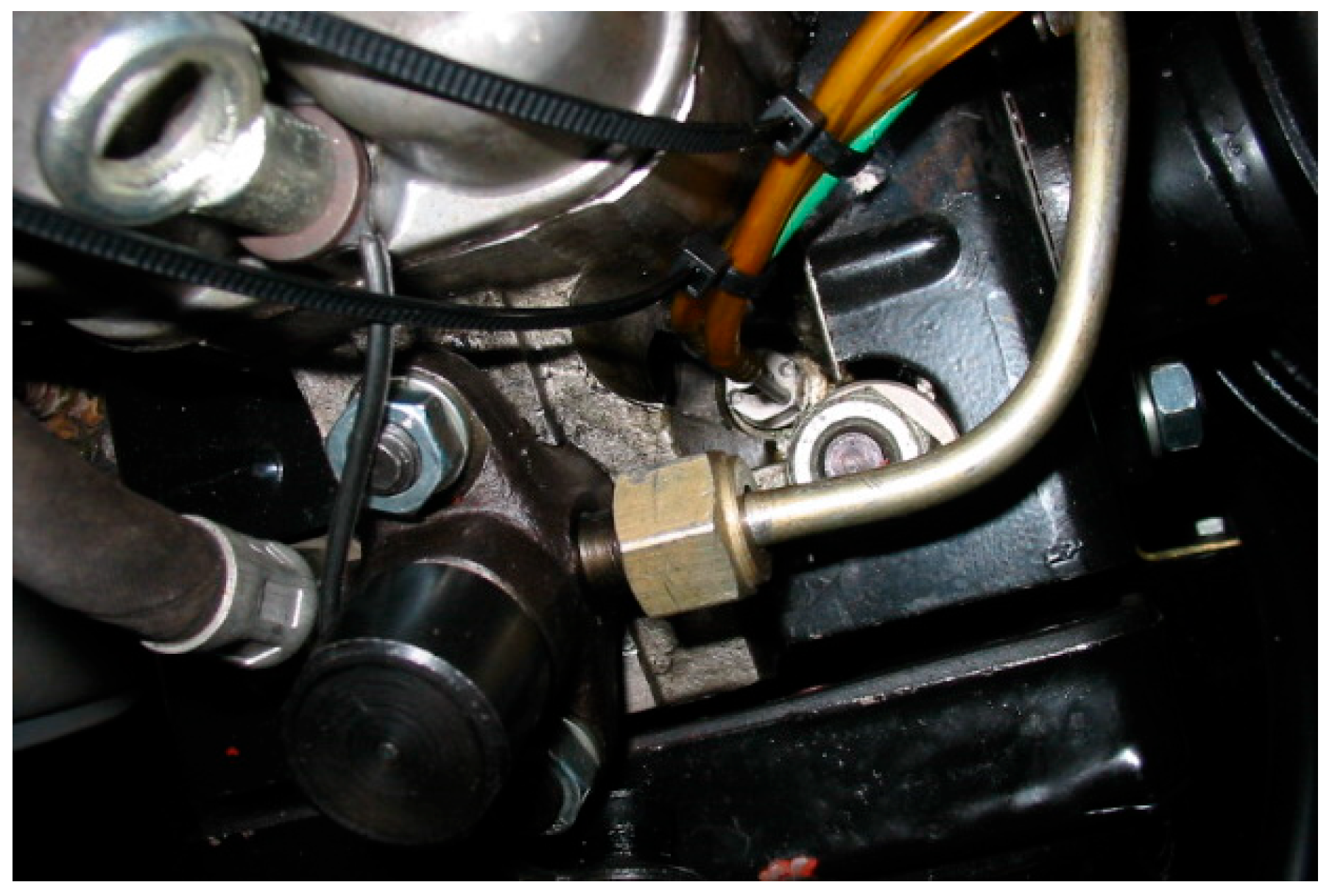
Diesel fuel injection timing is regulated by changing the SOI angle. Regulation was performed mechanically by adding washers of different thicknesses for the fuel injector in the cylinder head (Figure 2). Tests were carried out with five different SOI values: 14, 16, 18.5, 21, and 25.6 cad BTDC.

3.1.1. Test Bench with Measuring and Data Acquisition System Description

A description of the installation with equipment for pressure indication and exhaust gas analysis, as well as for data processing, is shown in Table 6.
In order to make accurate measurements and comparisons, a water-cooled cylinder pressure transmitter was used to indicate mean effective pressure (IMEP) and specific fuel consumption (ISFC) calculations. Cylinder pressure has been recorded and averaged according to the number of cycles in the cylinder and an appropriate cad resolution [21].

3.1.2. Operating Points and PM Emission Calculation

The engine test was carried out according to the conditions and regimes prescribed by the standard European Stationary Cycle (ESC). The steady operating modes selected for the test range from first mode under idle with a 15% load or 0.015 MPa brake mean effective pressure (BMEP). Indications were then realized for the other 12 modes defined by the ESC conditions at 1960, 2325, and 2690 rpm (Table 7) [71,72].
The sampled emissions were converted into mass flow [g∙h−1] in each ESC mode under standard conditions, as prescribed by the ESC standard. The density of combustion products is adopted as ρ = 1.293 kg/m3 at a temperature of 273 K (0 °C) and a pressure of 101,325 kPa.
Given that the smoke or opacity of the combustion products was measured with a smoke meter type AVL 409, for the calculation of the specific emission of PM, it was necessary to first recalculate the opacity obtained according to the BOSCH method, smoke number (SN), and filter smoke number (FSN) for all results. The recommended correlation between SN (measured with AVL 409) and FSN (measured with AVL 415) was used [73]:
FSN = SN × (0.87)−1
Considering that we used an opacimeter that does not require preheating before measurement, the old correlation curve was used for further calculation for the computational transformation of the opacity from the combustion products into the PM concentration (PM-conc) [73].
The PM-conc in [mg∙m−3] is calculated using the following equation:
PM-conc = 1 × (0.405)−1 × α × FSN × exp(β × FSN)
Equation (2), as shown above, is valid for the case FSN ≤ 8 on the old correlation curve when α = 4.95 and β = 0.38.
The mass concentration of PM (PM-mass) [g∙h−1] for normal conditions is calculated using the following equation [73]:
PM-mass = 1 × (1.293)−1 × PM-conc × G-exh
where G-exh represents raw exhaust gas mass flow [g∙h−1] or sum of fuel (m-fuel) and air (m-air) mass flow:
G-exh = m-fuel + m-air
The specific emission of PM [g∙kW−1∙h−1] is calculated using the following equation:
PM = ∑PM-mass × WFi × [∑P(n)I × WFi]−1
where WFi and P(n)i represent load factor and power in the appropriate i point or ESC mode. By applying the equations above for emission calculation of the experimental engine according to the ESC cycle, the individual, specific PM emissions in the corresponding mode (operating mode) were calculated.

3.2. Tribological Tests of the Aluminum Cylinder Sliding Surface with Steel Reinforcement

The tribological tests included damaged samples of the cylinder base material made of aluminum alloy with reinforcements of the sliding surface made of steel (Figure 3). To approximate the real conditions in the cylinder, tribological tests were carried out during the reciprocating sliding of the tribometer steel ball on the sample plate of the tested materials. Figure 3 shows a picture of the cylinder liner sample that was used in tribological research.
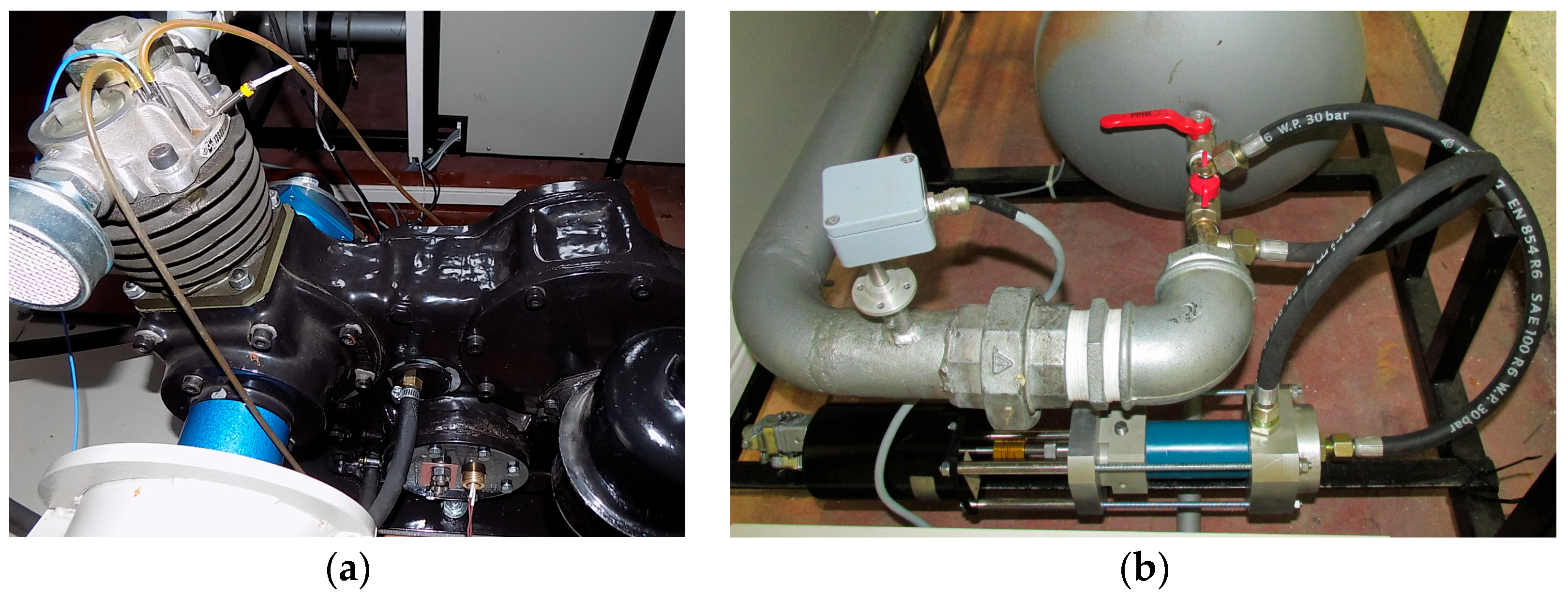
The tribologically optimized cylinder is part of a reciprocating air compressor within the test bench for recording performance characteristics in laboratory conditions [74]. The test bench for testing the performance of reciprocating air compressors was specially designed to analyze valve plate dynamics caused by stiction under oil presence on the seat and limiter inside the valve construction (Figure 4) [75,76]. In the next stage of development, the test bench is equipped with a block constructed for loading and simulating working conditions. For this purpose, an automatic servo valve is designed and integrated into the installation, which has the role of finely regulating compressed air pressure and quick establishment of the working mode. In this way, working conditions are simulated, that is, the activation of compressed air consumers on vehicles (Figure 4).
Considering that tribological research and verification of the construction of the cylinder or piston are not sufficient for the decision on eventual serial production, the test results on the test bench (Figure 4) play a key role. The test bench can also be used to record the performance of the automatic servo valve with an electrohydraulic servo system in a closed loop.

3.2.1. Applied Materials and Tribometer: Tests under Sliding Conditions

The tested base material of the reconstructed reciprocating compressor cylinder is basically an AlSi alloy (EN AlSi10Mg) with the following chemical composition: Al-9.8Si-0.48Fe-0.1Cu-0.2Mn-0.3Mg-0.08Zn-0.05Ti [wt.%]. The chemical composition of the ferrous-based reinforcements of the sliding surface of the cylinder liner is an alloy with the following chemical composition: Fe-1.2C-1.5Mn-1.3Cr-0.3Ni [wt.%] (Figure 3).
The base construction of the cylinder, before reconstruction, was made of a heavier gray cast iron alloy (SL 26), whose chemical composition is as follows: Fe-3.18C-2.17Si-0.60Mn-0.7P-0.37Cr [wt.%].
Samples of materials for testing on the tribometer were obtained by cutting the cylinder in a plane normal to the plane along the longitudinal axis of the cylinder. The dimensions of the samples are 6.35 × 15.75 × 10.16 mm (Figure 3).
The mechanical processing of the samples was first performed by sanding with SiC paper with size granules (P800 and P1200), then cleaning with ethyl alcohol in an ultrasonic bath for 30 min, and cleaning with a cotton cloth and ethyl alcohol. In this way, the purity and initial roughness of the samples Ra = 0.3 μm were ensured.
The tribometer ball, which makes sliding contact with the tested materials, is made of commercial Al2O3 and has a diameter of 1.5 mm.
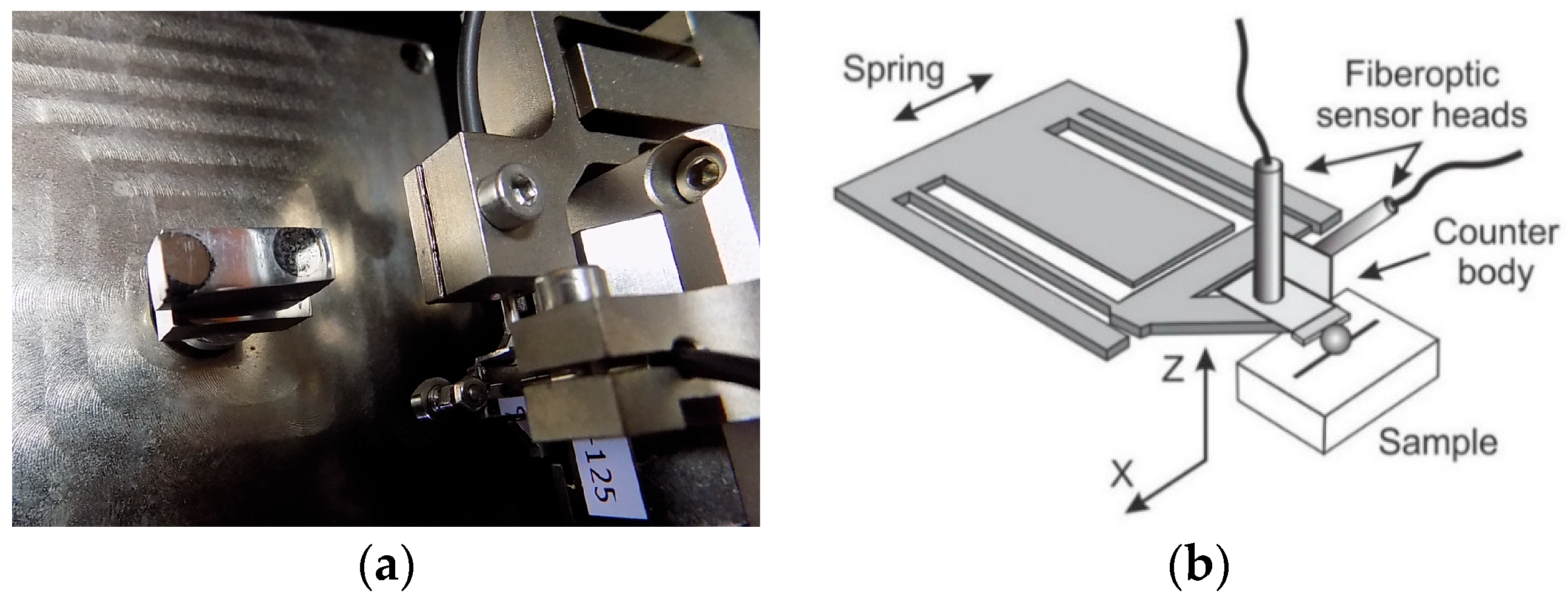
Tribological tests were performed according to the standard ASTM G133-05 method (ASTM International, West Conshohocken, PA, USA) under laboratory ambient conditions. On the tribometer, tribometer ball-type contact was made on a plate made of a sample of the tested materials in sliding conditions with and without lubricating oil. The tribometer manufactured by CSM Instruments SA, Peuseux, Switzerland, inside the Center for Tribology, was used for testing (Figure 5) [39,40].
Tribological tests were carried out by applying an appropriate force normal to the area of the tested material in the form of a plate. For this, the CSM tribometer is equipped with a module for linear reciprocating motion during sliding and a ball-shaped counter body attached to the tribometer console (Figure 5).
The tribometer is equipped with an appropriate software package with various possibilities for processing and displaying test results. The software that supports the used tribometer has a commercial name on the market TriboX version 2.9.0 (CSM Instruments SA, Peuseux, Switzerland).
A microscope was used for the tribological characterization and measurement of wear tracks on damaged surfaces, with the aim of determining the characteristic sizes of wear of the examined materials. The microscope is equipped with commercial software named SEM (scanning electron microscope), manufactured by Meiji Techno Co. Ltd., Chikumazawa, Japan.
A more complete analysis of the damaged and worn samples of the tested material in characteristic areas was performed based on micrographs and the chemical composition of their surface. The analysis was carried out using the material spectroscopy method EDS (energy-dispersive spectroscopy). This method essentially involves the exposure of certain areas on the damaged surface of the material to electromagnetic radiation. In this way, the SEM/EDS system was formed, or the Phenom ProX Desktop SEM system, with the possibility of an EDS application.

3.2.2. Applied Load and Speed Parameters during Tribological Tests

The tests were carried out in conditions with and without a lubricant, the influence of which was considered independently. During the tribological tests, the values of the friction coefficient and wear were measured for three different values of normal force of 0.3, 0.6, and 0.9 N and sliding speeds of 3, 9, and 15 mm/s. The test was performed with 500 contact cycles (lap or lap number) in each test mode (corresponding to a distance, i.e., a sliding path of 1 m), with half of the amplitude of 0.5 mm. Data acquisition was realized at a frequency of 50 Hz. During the test, the ambient temperature was maintained in the range of 21 ± 2 °C, while the air humidity was 45%.
In each mode, the acquisition software package TriboX 2.9.0 was used to record the friction coefficient value per unit of time. After testing in each mode, the sample was photographed with an optical microscope (SEM). The wear of the sliding surface of the tested material was evaluated by measuring the penetration depth and by precisely measuring the dimensions of the worn layers (photographed traces of wear) using photo processing software Infinity Analyze version 7 (Teledyne Lumenera, Ottawa, ON, Canada). The volume of wear tracks after damage and the degree of wear were calculated for each mode according to the conditions of the standard ASTM G133-05 (ASTM International, West Conshohocken, PA, USA) for the sliding distance of 1 m.
The worn volume on the surface of the sample was calculated for the maximum value of the penetration depth of the tribometer ball for each test after the sliding distance of 1 m, while the degree of wear was calculated using Equation (6). In doing so, it was assumed that the worn volume corresponds to a flat segment of the material, i.e., the worn volume is bordered by a rectangle and is divided into segments of regular geometric shape.
Ww = Vw × (Sw)−1
where the variables represent the following:
  • Ww—degre of wear (mm3∙m−1);
  • Vw—volume of worn cylinder material (mm3);
  • Sw—sliding distance (m).
During the test, it was assumed that the wear of the tribometer ball was very low and that the surface layer was worn. During the test, in every regime, the steel ball slides alternately over the base material and the reinforcing material; this is similar to the real working conditions in the cylinder.
In this way, the coefficient of friction values were recorded as a function of the number of alternating sliding cycles and the distance for all test regimes, depending on the sliding speed and load. Characteristic photos of the wear of the base material and the reinforcement were also taken.
The fact is that the presence of a lubricating oil in the cylinder due to damage to the investigated sliding surface of the cylinder (inside a reciprocating air compressor or IC engine) can cause damage to the systems on the vehicle and harmful emissions of PM due to combustion or the presence of oil from the lubrication system in the environment. For this reason, during a certain period, research was initiated into the application of materials that have self-lubricating properties, such as solid lubricants and self-lubricating composites, which are particularly interesting when used in the cylinder assembly of reciprocating machines as well as second parts [76,77].
In this connection, much research can be found that aims to apply reciprocating compressors without the direct presence or with the minimal presence of lubricating oil [78,79].
Therefore, this paper presents only the results of tribological tests of cylinder materials without the presence of lubricating oil. The test was performed in parallel with the presence of appropriate lubricating oil, but the results are the subject of other research by the author.

4. Results

4.1. Particulate Matter Emissions from the Diesel Engine on the Test Bench

The influence of CR on the change in mean maximum temperature (Tmax) and pressure (Pmax) in the cylinder was also analyzed, and the results are shown in Figure 6. The results were obtained by testing the engine at maximum load (BMEP), as well as at constant engine speed (2325 rpm) and diesel fuel SOI timings. The results indicate that with an increase in CR value as well as SOI (in this case, starting from 14–18.5 cad BTDC), the values of Pmax and Tmax in the cylinder increase in parallel. The main cause of the undesirable increase in Pmax and Tmax with increasing SOI and CR values is the lack of classical mechanical injection systems and constant CR values. Due to the injection of a larger amount of diesel fuel into the cylinder under favorable conditions for more complete combustion (higher pressures and temperatures, better mixing, and a more complete air/fuel mixture), the values of Pmax and Tmax are also higher, which is the main consequence.
Contrary to the previous one, by reducing the CR and SOI values, the conditions for more complete combustion in the cylinder are worse. In that case, due to the shorter time for mixture preparation and fuel combustion, the ignition delay period is longer, so a greater amount of heat due to the combustion process is released after TDC, which increases the temperature during the expansion process as well as the temperature of the exhaust gases.
Due to the reduction in SOI and stretching the combustion process to the expansion, i.e., afterburning, brake-specific fuel consumption (BSFC) increases, and smoke emissions are higher, which is accompanied by an increase in PM emissions (Figure 7).
One of the reasons for the reduction in Tmax in the cylinder, which results in an increase in smoke and PM emissions, is an increase in the volume of the combustion chamber at the piston bowl in order to mechanically reduce the value of CR (Table 5). In this case, due to the larger volume of the combustion chamber at the piston bowl, the swirling of air slows down, and the process of extrusion of the combustion products from the cylinder takes longer, which results in extinguishing the flame and reducing NOx emissions while also increasing smoke and PM emissions (Figure 7). Also, at the same time, the process of heat exchange between the combustion products, the walls of the combustion chamber, and the cylinder with the cooling medium and the environment takes longer. The decrease in PM emission values with increasing SOI values is connected with a parallel increase in the air–fuel ratio coefficient in the cylinder, which enables more complete combustion.
On the other hand, the diagrams in Figure 7 indicate that at full engine loads, PM and smoke emissions decrease with increasing SOI values, i.e., increase with increasing CR, at medium as well as at higher engine speeds. As already explained above, lean engine operation is the main cause of the reported decrease in PM emissions with increasing SOI values. In that case, it is assumed that better mixture preparation at lower CR values generally results in a reduction in PM emissions without necessarily increasing in-cylinder Tmax.
The general conclusion is that the emission of PM and smoke seriously depends on the temperature and pressure during the combustion process in the cylinder and increases intensively with the increase in their value.
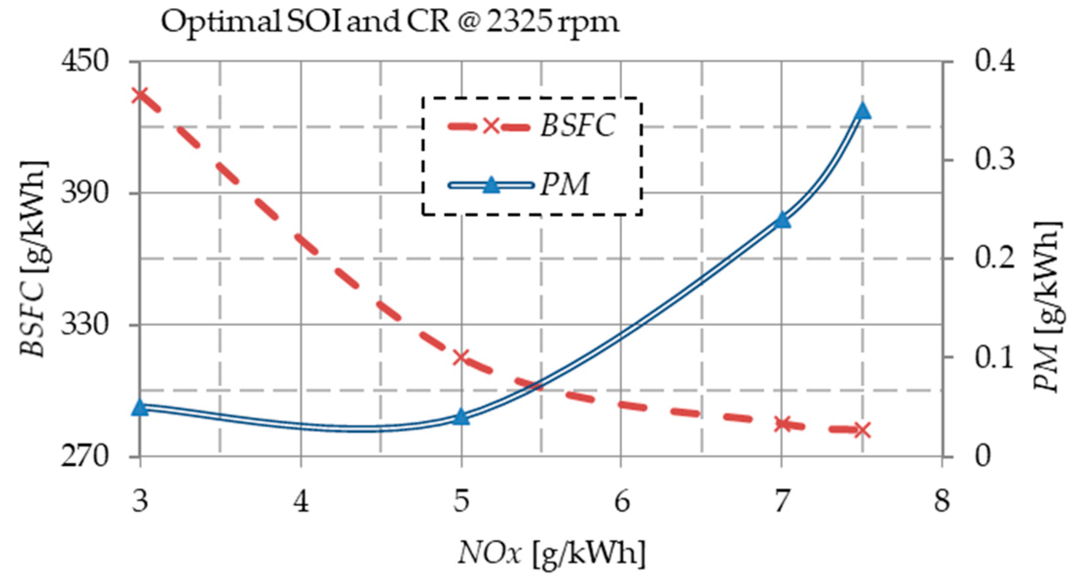
At a higher engine speed of 2325 rpm and an optimal SOI value, the minimum PM emission is achieved at a lower load of BMEP = 0.39 MPa, compared to a higher load at BMEP = 0.55 MPa, when a higher PM emission is recorded (Figure 8).
Also, it can be observed that the proposed simultaneous changes in CR and SOI values during the work process in the IC engines are necessary to reduce exhaust emissions and fuel consumption. With the application of modern and sustainable technologies, it is also practically applicable. This is indicated by recorded trade-offs between fuel consumption, PM, and NOx emissions at optimal CR and SOI values and a higher engine speed of 2325 rpm (Figure 8).
The fact is that a later SOI timing technology is also applicable from the perspective of reducing NOx emissions in relation to the smoke limit conditions and working with minimal BSFC (Figure 8).
Based on Equations (1)–(5), the emission of PM and NOx was also calculated and presented depending on CR and SOI at a constant engine speed. The conditions are defined according to the ESC cycle for the non-road and stationary engines (Figure 9).
According to the diagrams obtained by applying the conditions of the ESC emission cycle, it is also possible to confirm that the PM emission decreases with increasing SOI timing while the NOx emission increases. With an increase in the CR value, the emission of PM increases intensively, especially at a lower value of SOI = 14 cad BTDC, while in parallel, there is a slight increase in the emission of NOx (Figure 9).
The obtained results and dependences are similar to those obtained by other researchers (Figure 10) [80].
The obtained results can also be compared with the results presented in the literature [80], where the influence of smoke emissions resulting from the combustion of engine oil is also emphasized. From the second side, engine oil contaminated with PM and soot contributes to increased wear of parts and accelerates the occurrence of failures during exploitation.
In this way, the importance of tribological optimization of the piston and cylinder liner design of the IC engines and reciprocating compressors as peripheral equipment was also pointed out.

4.2. Results of a Tribological Investigation of a Cylinder Liner Sample with Reinforcements

The results of the investigation of the cylinder material sample with aluminum alloy base and cast-iron reinforcements (Figure 3) by applying SEM/EDS analysis are presented in the research [45,46]. Characteristic zones were identified on the surface of the investigated material sample, of which the transition zones between the base material and the reinforcement are particularly characteristic. The results of the research on medium and low loads of the material are partly presented in the other scientific works.

Friction Coefficient and Penetration Depth of a Worn Sample of the Aluminum Cylinder with Reinforcements at Maximum Load and Sliding Speed

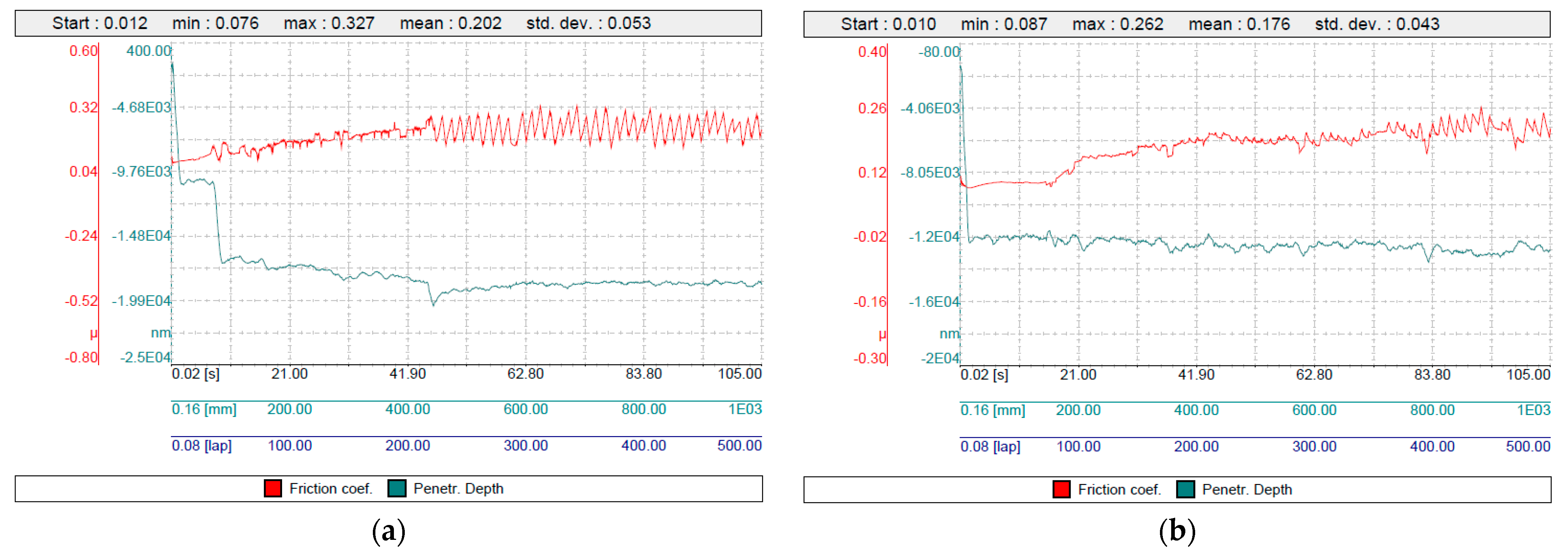
The results of the tribological investigation of the worn cylinder material sample after sliding tests regarding friction coefficient and penetration depth value changes for higher maximum loads 0.9 N and higher sliding speed 0.015 m/s are shown in Figure 11.
During maximum load and sliding speed conditions, a curve with larger oscillations relating to the penetration depth value of the tribometer ball into the cylinder base material sample was recorded. In the case of the reinforcement material, the value of the penetration depth is relatively constant during the test, with uniform oscillations around the mean value (Figure 11), which indicates less and more even wear. These are the expected results, given that the material of the base of the cylinder is less hard than the material of the reinforcement.
In the modes of maximum load and maximum sliding speed, lower maximum and mean values relating to the friction coefficient of reinforcement material (0.262 and 0.176) compared to the base cylinder material (0.327 and 0.202) were recorded (Figure 11).
By comparing the results received under the maximum sliding speed, it can be seen that the maximum and mean values relating to the friction coefficient of the cylinder base material at maximum load (0.327 and 0.202) and the reinforcement material (0.262 and 0.176) are lower compared to the comparable values recorded at the same sliding speed at medium load (0.370 and 0.226) for the base material and (0.328 and 0.227) for the reinforcement material. At the same maximum sliding speed, with a decrease in load, there was an increase in the coefficient of friction [45,46].
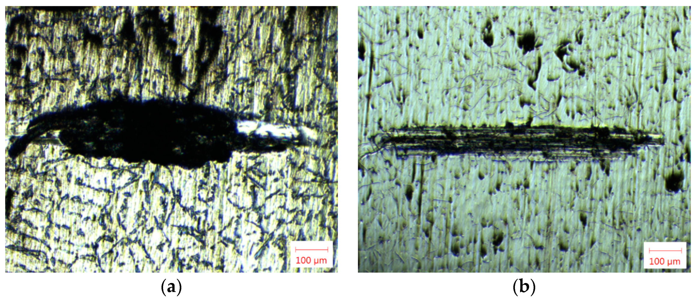
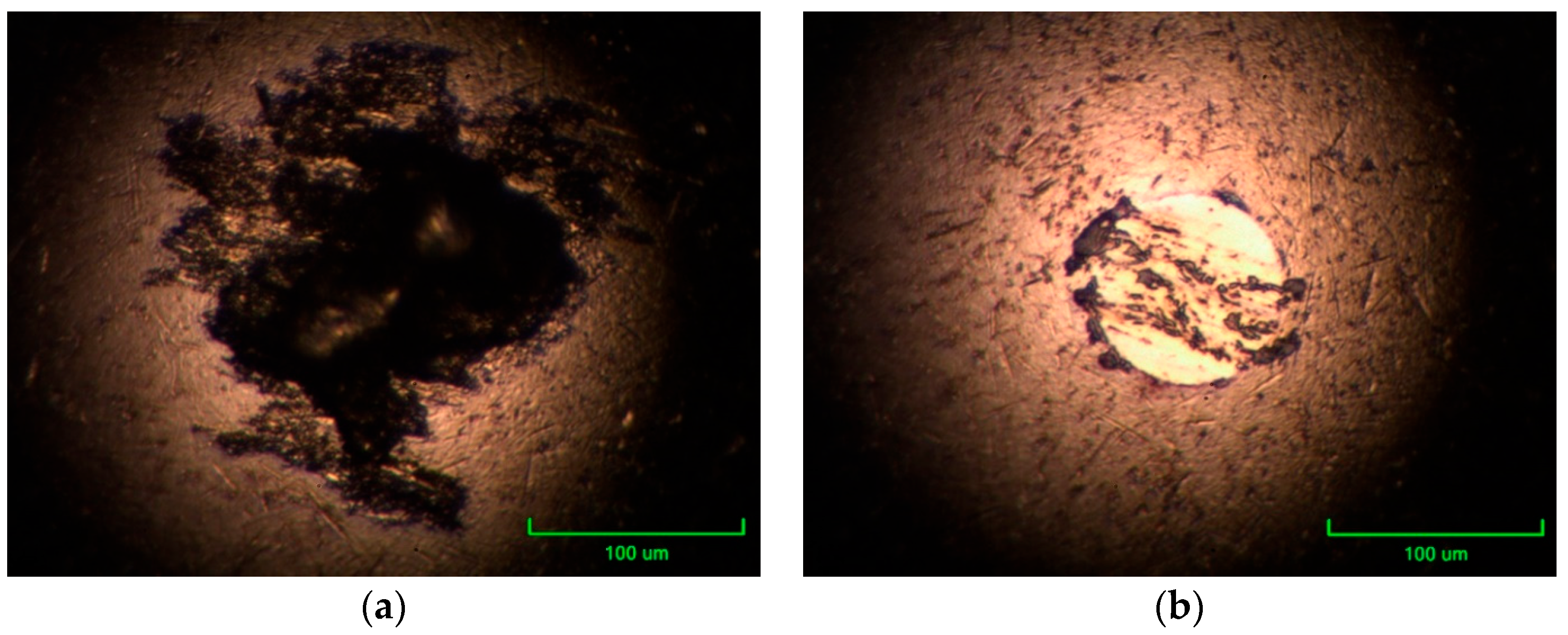
By analyzing the wear trace of the base material, it is concluded that intense adhesive wear has occurred (Figure 12). The consequence of adhesive wear is the occurrence of transfer and sticking of the base material, which is why the deposits on the tribometer ball were recorded (Figure 13). Due to the reciprocating process related to transferring and sticking materials from one surface to another in sliding contact, at a certain moment, there was contact between the same materials, which had the effect of balancing the friction coefficient value after the sliding distance of 0.45 m, as can be seen in Figure 11.
On the worn surface of the reinforcement material sample, a layer of transferred material can be observed covering the grooves that are arranged in the form of parallel lines (Figure 12) due to the consequences of abrasive wear. On the micrograph of the counter body ball, there are no signs of wear, but a thin layer of the transferred material can be seen (Figure 13).
The wear of the reinforcement material is uniform; the established values of the penetration depth were recorded without traces of abrasive wear. This fact does not apply to the tests with the base material. The base material is less hard and is subject to adhesive wear due to the sticking and transfer of material from one surface to another, which affects the course of the change in the curve of dependence of the friction coefficient and the penetration depth.
Considering the aim of the research to tribologically approve the optimization of the reciprocating compressor cylinder made of aluminum alloy with reinforcements of the sliding surface, based on the results of tribological tests, this can be achieved by applying continuously distributed reinforcements. Recorded lower values related to the friction coefficient of the reinforcement material indicate that the application of the reinforcement can also contribute to the reduction in mechanical losses, which are a direct consequence of friction in reciprocating compressors as well as IC engines.

5. Discussion

This paper includes experimental investigations of diesel engine characteristics on a test bench in laboratory conditions. For this purpose, a zero-dimensional mathematical model developed at the Faculty of Engineering, University of Kragujevac, was used, as well as the accompanying software AVL IndiCom Indicating Software version 1.2 (AVL List GmbH, Graz, Austria). For this purpose, a literature analysis with a similar research topic was previously performed. This paper pointed out the importance of occupational health and the formation of low-emission zones, following the example of large European cities, which are defined by appropriate regulations. A review of the legislation relating to exhaust gas emissions in the EU, which must be met by vehicles using IC engines as propulsion systems, was also carried out. The emphasis of the research is to approve the application of diesel engines with variable systems in order to meet emission regulations, primarily from the aspect of minimal PM emissions. For this purpose, the impact of changing CR, SOI, engine speed, and load on the combustion process and emissions was analyzed. This paper presents the results of the research within the experimental engine with descriptions related to the equipment used for testing on the test bench. Test conditions are systematized. The change in CR was realized mechanically by changing the volume of the combustion chamber or piston bowl in the piston head, while the change in SOI timings was also realized mechanically by changing the thickness of the fuel injection washer in the cylinder head. Engine emissions are measured under ESC cycle conditions. Tests of the experimental engine were carried out under the following conditions, which are illustrated in parallel on the corresponding diagrams:
  • Changes in Tmax and Pmax under a higher engine speed of 2325 rpm and a full load of 0.55 MPa depending on CR values for SOI = 14 cad BTDC and SOI = 18.5 cad BTDC;
  • Changes in smoke and PM emissions under a full load of 0.55 MPa and a middle engine speed of 1960 rpm depending on CR values for SOI = 14 cad BTDC and SOI = 18.5 cad BTDC and under a higher engine speed of 2325 rpm for SOI = 14 cad BTDC and SOI = 18.5 cad BTDC;
  • Influence of CR and load under a higher engine speed of 2325 rpm and optimal SOI on PM emission and relations between PM emission and BSFC vs. NOx emission for optimal SOI and CR values under a higher engine speed of 2325 rpm;
  • Relations between PM and NOx emissions depending on the CR value according to ESC emission cycle conditions under SOI = 14 cad BTDC and SOI = 18.5 cad BTDC.
The conclusion is that by applying variable systems to IC engines, the level of raw emissions of exhaust and harmful combustion products can be successfully regulated.
On the other hand, in parallel, this paper investigated the tribological optimization of the cylinder sliding surface made of aluminum alloy in the example of a reciprocating air compressor for brake systems in motor vehicles. The conditions of the tribological testing related to the material sample of the cylinder liner with reinforcements are systematized. The test of the material sample was performed under sliding conditions without lubrication on a ball-on-plate-type tribometer. The results presented in this paper are illustrated with appropriate diagrams and were obtained under conditions of maximum experimental load and sliding speed:
  • Friction coefficient and penetration depth change depending on the sliding time, distance, and cycles at constant maximum load and sliding speed, 0.9 N and 0.015 m/s, for the base material and for the reinforcement;
  • Optical micrographs of damaged material surfaces after the sliding test at constant load of 0.9 N and speed of 0.015 m/s conditions for the base material and the reinforcement;
  • Optical micrographs of the tribometer counter body ball surface after testing the material at a constant load of 0.9 N and speed of 0.015 m/s for the cylinder base and for reinforcement.
The results of tribological research indicate that by applying tribological reinforcements, it is possible to achieve a reduction in the friction coefficient and, thus, mechanical losses, which can contribute to a reduction in fuel consumption and PM emission. By applying reinforcement to the sliding surface of the aluminum cylinder, the wear rate was also reduced, thus confirming one of the initial hypotheses.
Due to the reduction in wear, the service life of the sliding surface of the cylinder is extended, which prevents the blow-by of oil into the combustion chamber, which contributes to the reduction in PM emissions resulting from oil combustion. Conversely, increasing the wear resistance of the cylinder sliding surface prevents contamination of the lubricating oil due to the penetration of combustion products into the crankcase, which can prevent sudden failures due to the acidity of the lubricant and increased wear of IC engine as well as reciprocating compressor parts.

6. Conclusions

In this manuscript, the effect of CR and SOI timing changes in experimental single-cylinder engine exhaust emissions is investigated.
The aim of this work is to point out the application of automatic technology, i.e., simultaneous change in the CR value, depending on the operating regime and fuel quality of the diesel engine. This paper analyzes the possibility of optimizing the combustion process in the cylinder of a diesel engine using variable CR and SOI timings, especially from the aspect of minimal PM emissions and smoke.
This paper indicated that, by applying simultaneous and automatic CR value change, it is possible to operate the diesel engine with a higher CR value during cold start and acceleration, as well as at full load with optimally lower CR values, etc.
Also, a brief review of the literature was carried out in order to point out the trend of applying modern technologies to diesel engines.
Based on the review of the relevant literature and the results of experimental research, the conclusions are as follows:
(i)
Due to their good fuel economy, diesel engines have potential as power units for hybrid vehicles. At the same time, it is necessary to reduce the emissions of NOx and PM, i.e., the smoke from diesel engines, due to their extremely negative impact on human health and the pollution of the environment with harmful exhaust gases;
(ii)
The emission of exhaust gases from diesel engines is increasingly limited over time by strict emission regulations. Therefore, modern technologies were developed and applied over time, such as direct fuel injection under high pressure, supercharging, exhaust gas recirculation, a variable valve train, homogenous charge compression ignition, lowering engine displacement, catalytic treatment of raw combustion products, particle filters, etc.;
(iii)
This paper proposes the application of an automatically variable compression ratio. The research results can be used when constructing such IC engines, which should contribute to lower emissions and fuel consumption;
(iv)
At a maximum engine speed of 2325 rpm and a full load of 0.55 MPa, a decrease in Tmax and Pmax in the cylinder can be observed with a decrease in the values of CR and SOI;
(v)
The consequence of the reduction in Tmax in the cylinder when reducing the CR and SOI values at the maximum experimental engine speed and full load is the increased emission of PM and smoke, which, on the other hand, contributes to the reduction in NOx emissions. A similar dependence was recorded at an average engine speed of 1960 rpm and a full load of 0.55 MPa;
(vi)
At the maximum engine speed of 2325 rpm under the optimum SOI value, the minimum PM emission was achieved at low engine loads;
(vii)
With later SOI timing, it is possible to achieve engine operation at the smoke limit with minimal BSFC and NOx emissions;
(viii)
The combustion of engine oil that blows into the cylinder due to the wear of the cylinder liner sliding surface is one of the important sources of PM and smoke emissions inside IC engines.
(ix)
At the maximum load of 0.9 N and maximum sliding speed of 0.015 m/s according to the experimental conditions, the mean value of the friction coefficient of the reinforcement 0.176 is lower compared to the comparative value for the cylinder base material 0.202;
(x)
At maximum load and sliding speed, the material of the reinforcement wears evenly and less intensively, so the wear curve does not have pronounced oscillations, which is not the case with the material of the cylinder base, which is made of a softer aluminum alloy;
(xi)
Analyzing the optical micrographs of the worn cylinder surface material sample, it was observed that during the investigation of the base material, there was a recorded sticking of the material, which intensified the process of adhesive wear. This is not the case with the reinforcement material, which is harder and whose surface shows traces of abrasive wear, and no material transfer, i.e., adhesive wear, was recorded;
(xii)
The tribological optimization of the cylinder indicates the further verification of the construction with reinforcements from the aspect of reducing mechanical losses, i.e., fuel consumption and emissions.

Author Contributions

Conceptualization, S.M. and J.G.; methodology, S.M.; software, S.M.; validation, J.G., S.S. and B.S.; formal analysis, S.S. and G.B.; investigation, S.M.; resources, S.M.; data curation, S.M. and G.B.; writing—original draft preparation, S.M.; writing—review and editing, S.M. and J.G.; visualization, S.M. and M.B.; supervision, B.S. and M.B.; funding acquisition, B.S. All authors have read and agreed to the published version of the manuscript.

Funding

This paper is a result of the research within the project TR35041 supported by the Ministry of Science, Technological Development and Innovation of the Republic of Serbia.

Informed Consent Statement

Not applicable.

Data Availability Statement

Data will be provided via the SCIDAR-A Digital Archive of the University of Kragujevac: https://scidar.kg.ac.rs/ (accessed on 1 December 2023).

Acknowledgments

S.M. acknowledges any support from the Ministry of Science, Technological Development and Innovation of the Republic of Serbia.

Conflicts of Interest

The authors declare no conflicts of interest.

References

  1. Ravi, S.S.; Osipov, S.; Turner, J.W.G. Impact of Modern Vehicular Technologies and Emission Regulations on Improving Global Air Quality. Atmosphere 2023, 14, 1164. [Google Scholar] [CrossRef]
  2. Vouitsis, I.; Portugal, J.; Kontses, A.; Karlsson, H.L.; Faria, M.; Elihn, K.; Juárez-Facio, A.T.; Amato, F.; Piña, B.; Samaras, Z. Transport-related airborne nanoparticles: Sources, different aerosol modes, and their toxicity. Atmos. Environ. 2023, 301, 119698. [Google Scholar] [CrossRef]
  3. Hao, Y.; Gao, C.; Deng, S.; Yuan, M.; Song, W.; Lu, Z.; Qiu, Z. Chemical characterization of PM2.5 emitted from motor vehicles powered by diesel, gasoline, natural gas and methanol fuel. Sci. Total Environ. 2019, 674, 128–139. [Google Scholar] [CrossRef]
  4. Liu, Y.; Zhang, W.; Yang, W.; Bai, Z.; Zhao, X. Chemical Compositions of PM2.5 Emitted from Diesel Trucks and Construction Equipment. Aerosol. Sci. Eng. 2018, 2, 51–60. [Google Scholar] [CrossRef]
  5. Xing, Y.; Xu, Y.; Shi, M.; Lian, Y. The impact of PM2.5 on the human respiratory system. J. Thorac. Dis. 2016, 8, E69–E74. [Google Scholar] [CrossRef] [PubMed]
  6. Garcia, A.; Santa-Helena, E.; De Falco, A.; De Paula Ribeiro, J.; Gioda, A.; Gioda, C.R. Toxicological Effects of Fine Particulate Matter (PM2.5): Health Risks and Associated Systemic Injuries—Systematic Review. Water Air Soil Pollut. 2023, 234, 346. [Google Scholar] [CrossRef] [PubMed]
  7. Gürbüz, H.; Şöhret, Y.; Ekici, S. Evaluating effects of the COVID-19 pandemic period on energy consumption and enviro-economic indicators of Turkish road transportation. Energy Sources Part A Recovery Util. Environ. Eff. 2021. [Google Scholar] [CrossRef]
  8. Reitz, R.D.; Ogawa, H.; Payri, R.; Fansler, T.; Kokjohn, S.; Moriyoshi, Y.; Agarwal, A.K.; Arcoumanis, D.; Assanis, D.; Bae, C.; et al. IJER editorial: The future of the internal combustion engine. Int. J. Engine Res. 2020, 21, 3–10. [Google Scholar] [CrossRef]
  9. Mustafi, N.N. An Overview of Hybrid Electric Vehicle Technology. In Engines and Fuels for Future Transport. Energy, Environment, and Sustainability; Kalghatgi, G., Agarwal, A.K., Leach, F., Senecal, K., Eds.; Springer: Singapore, 2022; pp. 73–102. [Google Scholar] [CrossRef]
  10. Correa, G.; Muñoz, P.M.; Rodriguez, C.R. A comparative energy and environmental analysis of a diesel, hybrid, hydrogen and electric urban bus. Energy 2019, 187, 115906. [Google Scholar] [CrossRef]
  11. Skrúcaný, T.; Kendra, M.; Stopka, O.; Milojević, S.; Figlus, T.; Csiszár, C. Impact of the Electric Mobility Implementation on the Greenhouse Gases Production in Central European Countries. Sustainability 2019, 11, 4948. [Google Scholar] [CrossRef]
  12. Eichinger, T.; Silberhorn, G.; Hofmann, S. MAN Smart Hybrid Experience. In Heavy-Duty-, On-und Off-Highway-Motoren 2021; Liebl, J., Ed.; Springer: Wiesbaden, Germany, 2022; pp. 202–218. [Google Scholar] [CrossRef]
  13. Fiebig, M.; Wiartalla, A.; Holderbaum, B.; Kiesow, S. Particulate emissions from diesel engines: Correlation between engine technology and emissions. J. Occup. Med. Toxicol. 2014, 9, 6. [Google Scholar] [CrossRef] [PubMed]
  14. Balaji, R.; Yeditha, V.S.; Premkumar, B.C.; Talari, S.; Madaka, R.M.R.; Edara, G. Controlling NOx in modified high pressure split injection single cylinder diesel engine with EGR-A mathematical approach. Int. J. Heat. Technol. 2023, 41, 679–686. [Google Scholar] [CrossRef]
  15. Zhai, C.; Chang, F.; Jin, Y.; Luo, H. Investigations on the Diesel Spray Characteristic and Tip Penetration Model of Multi-Hole Injector with Micro-Hole under Ultra-High Injection Pressure. Sustainability 2023, 15, 11114. [Google Scholar] [CrossRef]
  16. Zhang, Z.; Liu, H.; Yue, Z.; Wu, Y.; Kong, X.; Zheng, Z.; Yao, M. Effects of Multiple Injection Strategies on Heavy-Duty Diesel Energy Distributions and Emissions under High Peak Combustion Pressures. Front. Energy Res. 2022, 10, 857077. [Google Scholar] [CrossRef]
  17. Agarwal, A.; Solanki, V.; Krishnamoorthi, M. Experimental Evaluation of Pilot and Main Injection Strategies on Gasoline Compression Ignition Engine—Part 2: Performance and Emissions Characteristics. SAE Int. J. Engines 2023, 16, 833–852. [Google Scholar] [CrossRef]
  18. Chen, Y.; Li, X.; Shi, S.; Zhao, Q.; Liu, D.; Chang, J.; Liu, F. Effects of intake swirl on the fuel/air mixing and combustion performance in a lateral swirl combustion system for direct injection diesel engines. Fuel 2021, 286, 119376. [Google Scholar] [CrossRef]
  19. Sarangi, A.K.; McTaggart-Cowan, G.P.; Garner, C.P. The Impact of Fuel Injection Timing and Charge Dilution Rate on Low Temperature Combustion in a Compression Ignition Engine. Energies 2023, 16, 139. [Google Scholar] [CrossRef]
  20. Akolaş, H.İ.; Kaleli, A.; Bakirci, K. Design and implementation of an autonomous EGR cooling system using deep neural network prediction to reduce NOx emission and fuel consumption of diesel engine. Neural Comput. Appl. 2021, 33, 1655–1670. [Google Scholar] [CrossRef]
  21. Milojević, S.; Savić, S.; Marić, D.; Stopka, O.; Krstić, B.; Stojanović, B. Correlation between Emission and Combustion Characteristics with the Compression Ratio and Fuel Injection Timing in Tribologically Optimized Diesel Engine. Teh. Vjesn. 2022, 29, 1210–1219. [Google Scholar] [CrossRef]
  22. Martins, J.; Brito, F.P. Alternative Fuels for Internal Combustion Engines. Energies 2020, 13, 4086. [Google Scholar] [CrossRef]
  23. Kashyap, D.; Das, S.; Kalita, P. Influence of Oxygenated Fuel and Additives in Biofuel Run Compression Ignition Engine. In Potential and Challenges of Low Carbon Fuels for Sustainable Transport. Energy, Environment, and Sustainability; Agarwal, A.K., Valera, H., Eds.; Springer: Singapore, 2022; pp. 183–243. [Google Scholar] [CrossRef]
  24. Gürbüz, H.; Demirtürk, S.; Akçay, İ.H.; Akçay, H. Effect of port injection of ethanol on engine performance, exhaust emissions and environmental factors in a dual-fuel diesel engine. Energy Environ. 2020, 32, 784–802. [Google Scholar] [CrossRef]
  25. Milojević, S. Sustainable application of natural gas as engine fuel in city buses: Benefit and restrictions. J. Appl. Eng. Sci. 2017, 15, 81–88. [Google Scholar] [CrossRef]
  26. Yuan, X.; Liu, H.; Gao, Y. Diesel Engine SCR Control: Current Development and Future Challenges. Emiss. Control Sci. Technol. 2015, 1, 121–133. [Google Scholar] [CrossRef]
  27. Zannis, T.C.; Katsanis, J.S.; Christopoulos, G.P.; Yfantis, E.A.; Papagiannakis, R.G.; Pariotis, E.G.; Rakopoulos, D.C.; Rakopoulos, C.D.; Vallis, A.G. Marine Exhaust Gas Treatment Systems for Compliance with the IMO 2020 Global Sulfur Cap and Tier III NOx Limits: A Review. Energies 2022, 15, 3638. [Google Scholar] [CrossRef]
  28. Choi, B.; Lee, K.; Son, G. Review of Recent After-Treatment Technologies for De-NOx Process in Diesel Engines. Int. J. Automot. Technol. 2020, 21, 1597–1618. [Google Scholar] [CrossRef]
  29. Shilov, V.; Potemkin, D.; Rogozhnikov, V.; Snytnikov, P. Recent Advances in Structured Catalytic Materials Development for Conversion of Liquid Hydrocarbons into Synthesis Gas for Fuel Cell Power Generators. Materials 2023, 16, 599. [Google Scholar] [CrossRef] [PubMed]
  30. Lott, P.; Deutschmann, O. Lean-Burn Natural Gas Engines: Challenges and Concepts for an Efficient Exhaust Gas Aftertreatment System. Emiss. Control Sci. Technol. 2021, 7, 1–6. [Google Scholar] [CrossRef]
  31. Cesur, I.; Akgündüz, M.; Çelik, H.A.; Çay, Y.; Ergen, G. Tribological Analysis and Optimization of Ring-Cylinder Couple Coated with Different Materials. Arab. J. Sci. Eng. 2023, 1–12. [Google Scholar] [CrossRef]
  32. Mishra, P.C.; Roychoudhury, A.; Banerjee, A.; Saha, N.; Das, S.R.; Das, A. Coated Piston Ring Pack and Cylinder Liner Elastodynamics in Correlation to Piston Subsystem Elastohydrodynamic: Through FEA Modelling. Lubricants 2023, 11, 192. [Google Scholar] [CrossRef]
  33. Dolata, A.J.; Wieczorek, J.; Dyzia, M.; Starczewski, M. Assessment of the Tribological Properties of Aluminum Matrix Composites Intended for Cooperation with Piston Rings in Combustion Engines. Materials 2022, 15, 3806. [Google Scholar] [CrossRef]
  34. Li, C.; Chen, X.; Liu, H.; Dong, L.; Jian, H.; Wang, J.; Du, F. Tribological Performance and Scuffing Resistance of Cast-Iron Cylinder Liners and Al-Si Alloy Cylinder Liners. Coatings 2023, 13, 1951. [Google Scholar] [CrossRef]
  35. Alshwawra, A.; Abo Swerih, A.; Sakhrieh, A.; Dinkelacker, F. Structural Performance of Additively Manufactured Cylinder Liner—A Numerical Study. Energies 2022, 15, 8926. [Google Scholar] [CrossRef]
  36. Stojanović, B.Ž.; Milojević, S.T. Characterization, manufacturing and application of metal matrix composites. In Advances in Materials Science Research; Wythers, M.C., Ed.; Nova Science Publishers: New York, NY, USA, 2017; Volume 30, pp. 83–113. [Google Scholar]
  37. Pawlus, P.; Koszela, W.; Reizer, R. Surface Texturing of Cylinder Liners: A Review. Materials 2022, 15, 8629. [Google Scholar] [CrossRef]
  38. Sandra, V.; Stojanović, B.; Ivanović, L.; Miladinović, S.; Milojević, S. Application of nanocomposites in the automotive industry. Mobil. Veh. Mech. MVM 2019, 45, 51–64. [Google Scholar] [CrossRef]
  39. Milojević, S.; Džunić, D.; Marić, D.; Skrúcaný, T.; Mitrović, S.; Pešić, R. Tribological Assessment of Aluminum Cylinder Material for Piston Compressors in Trucks and Buses Brake Systems. Teh. Vjesn. 2021, 28, 1268–1276. [Google Scholar] [CrossRef]
  40. Milojević, S.; Savić, S.; Mitrović, S.; Marić, D.; Krstić, B.; Stojanović, B.; Popović, V. Solving the Problem of Friction and Wear in Auxiliary Devices of Internal Combustion Engines on the Example of Reciprocating Air Compressor for Vehicles. Teh. Vjesn. 2023, 30, 122–130. [Google Scholar] [CrossRef]
  41. Holmberg, K.; Andersson, P.; Erdemir, A. Global energy consumption due to friction in passenger cars. Tribol. Int. 2012, 47, 221–234. [Google Scholar] [CrossRef]
  42. Holmberg, K.; Andersson, P.; Nylund, N.O.; Mäkelä, K.; Erdemir, A. Global energy consumption due to friction in trucks and buses. Tribol. Int. 2014, 78, 94–114. [Google Scholar] [CrossRef]
  43. Li, Y.; Huang, S.; Liu, Y.; Ju, Y. Recycling Potential of Plastic Resources from End-of-Life Passenger Vehicles in China. Int. J. Environ. Res. Public Health 2021, 18, 10285. [Google Scholar] [CrossRef] [PubMed]
  44. Skrúcaný, T.; Semanová, S.; Milojević, S.; Asonja, A. New Technologies Improving Aerodynamic Properties of Freight Vehicles. Appl. Eng. Lett. J. Eng. Appl. Sci. 2019, 4, 48–54. [Google Scholar] [CrossRef]
  45. Elwert, T.; Goldmann, D.; Römer, F.; Buchert, M.; Merz, C.; Schueler, D.; Sutter, J. Current Developments and Challenges in the Recycling of Key Components of (Hybrid) Electric Vehicles. Recycling 2016, 1, 25–60. [Google Scholar] [CrossRef]
  46. Almeida Streitwieser, D.; Arteaga, A.; Gallo-Cordova, A.; Hidrobo, A.; Ponce, S. Chemical Recycling of Used Motor Oil by Catalytic Cracking with Metal-Doped Aluminum Silicate Catalysts. Sustainability 2023, 15, 10522. [Google Scholar] [CrossRef]
  47. Milojević, S.; Pešić, R.; Lukić, J.; Taranović, D.; Skrucany, T.; Stojanović, B. Vehicles optimization regarding to requirements of recycling Example: Bus dashboard. In Proceedings of the IOP Conference Series: Materials Science and Engineering, Kragujevac, Serbia, 5–7 September 2019. [Google Scholar] [CrossRef]
  48. Milojević, S.; Miletić, I.; Stojanović, B.; Milojević, I.; Miletić, M. Logistics of electric drive motor vehicles recycling. Mobil. Veh. Mech. MVM 2020, 46, 33–43. [Google Scholar] [CrossRef]
  49. EU: Heavy-Duty Truck and Bus Engines. Available online: https://dieselnet.com/standards/eu/hd.php (accessed on 8 November 2023).
  50. Bielaczyc, P.; Woodburn, J. Trends in Automotive Emission Legislation: Impact on LD Engine Development, Fuels, Lubricants and Test Methods: A Global View, with a Focus on WLTP and RDE Regulations. Emiss. Control Sci. Technol. 2019, 5, 86–98. [Google Scholar] [CrossRef]
  51. Tapak, P.; Kocur, M.; Rabek, M.; Matej, J. Periodical Vehicle Inspections with Smart Technology. Appl. Sci. 2023, 13, 7241. [Google Scholar] [CrossRef]
  52. Botero, M.L.; Londoño, J.; Agudelo, A.F.; Agudelo, J.R. Particle Number Emission for Periodic Technical Inspection in a Bus Rapid Transit System. Emiss. Control Sci. Technol. 2023, 9, 128–139. [Google Scholar] [CrossRef]
  53. Melas, A.; Selleri, T.; Suarez-Bertoa, R.; Giechaskiel, B. Evaluation of Solid Particle Number Sensors for Periodic Technical Inspection of Passenger Cars. Sensors 2021, 21, 8325. [Google Scholar] [CrossRef]
  54. Dziedziak, P.; Szczepański, T.; Niewczas, A.; Ślęzak, M. Car reliability analysis based on periodic technical tests. Open Eng. 2021, 11, 630–638. [Google Scholar] [CrossRef]
  55. Giechaskiel, B.; Lahde, T.; Suarez-Bertoa, R.; Clairotte, M.; Grigoratos, T.; Zardini, A.; Perujo, A.; Martini, G. Particle number measurements in the European legislation and future JRC activities. Combust. Engines 2018, 174, 3–16. [Google Scholar] [CrossRef]
  56. Shin, J.; Kim, B.; Kim, H.-R. Characteristics of Occupational Exposure to Diesel Engine Exhaust for Shipyard Transporter Signal Workers. Int. J. Environ. Res. Public Health 2020, 17, 4398. [Google Scholar] [CrossRef]
  57. Biró, N.; Kiss, P. Euro VI-d Compliant Diesel Engine’s Sub-23 nm Particle Emission. Sensors 2023, 23, 590. [Google Scholar] [CrossRef]
  58. Krais, A.M.; Essig, J.Y.; Gren, L.; Vogs, C.; Assarsson, E.; Dierschke, K.; Nielsen, J.; Strandberg, B.; Pagels, J.; Broberg, K.; et al. Biomarkers after Controlled Inhalation Exposure to Exhaust from Hydrogenated Vegetable Oil (HVO). Int. J. Environ. Res. Public Health 2021, 18, 6492. [Google Scholar] [CrossRef]
  59. Landwehr, K.R.; Larcombe, A.N.; Reid, A.; Mullins, B.J. Critical Review of Diesel Exhaust Exposure Health Impact Research Relevant to Occupational Settings: Are We Controlling the Wrong Pollutants? Exp. Health 2021, 13, 141–171. [Google Scholar] [CrossRef]
  60. EU: Urban Vehicle Access Regulations. Available online: https://transport.ec.europa.eu/transport-themes/urban-transport/urban-vehicle-access-regulations_en (accessed on 9 November 2023).
  61. EU: Urban Access Regulations in Europe. Available online: https://urbanaccessregulations.eu/ (accessed on 8 December 2023).
  62. Milojević, S.; Pešić, R. Determination of Combustion Process Model Parameters in Diesel Engine with Variable Compression Ratio. J. Combust. 2018, 2018, 5292837. [Google Scholar] [CrossRef]
  63. Narayan, S.; Milojevic, S.; Gupta, V. Combustion Monitoring in Engines Using Accelerometer Signals. J. Vibroeng. 2019, 21, 1552–1563. [Google Scholar] [CrossRef]
  64. Milojević, S.; Dragojlović, D.; Gročić, D. CNG propulsion system for reducing noise of existing city buses. J. Appl. Eng. Sci. 2016, 14, 377–382. [Google Scholar] [CrossRef]
  65. Milojević, S.; Skrucany, T.; Milošević, H.; Stanojević, D.; Pantić, M.; Stojanović, B. Alternative Drive Systems and Environmentaly Friendly Public Passengers Transport. Appl. Eng. Lett. 2018, 3, 105–113. [Google Scholar] [CrossRef]
  66. Skrúcaný, T.; Milojević, S.; Semanová, Š.; Čechovič, T.; Figlus, T.; Synák, F. The Energy Efficiency of Electric Energy as a Traction Used in Transport. Transp. Tech. Technol. 2018, 14, 9–14. [Google Scholar] [CrossRef]
  67. Stark, M.; Härtl, M.; Jaensch, M.; Preuss, A.C.; Pryymak, K.; Matz, G.; Gohl, M. Clarification of Fuel and Oil Flow Behavior around the Piston Rings of Internal Combustion Engines—Simultaneous Analysis of Oil Flow Behavior and Oil Emissions during Transient Operation; SAE Technical Paper; No. 2023-32-0045; Society of Automotive Engineers of Japan: Tokyo, Japan, 2023. [Google Scholar] [CrossRef]
  68. Pardo-García, C.; Orjuela-Abril, S.; Pabón-León, J. Investigation of Emission Characteristics and Lubrication Oil Properties in a Dual Diesel–Hydrogen Internal Combustion Engine. Lubricants 2022, 10, 59. [Google Scholar] [CrossRef]
  69. Tomanik, E.; Christinelli, W.; Souza, R.M.; Oliveira, V.L.; Ferreira, F.; Zhmud, B. Review of Graphene-Based Materials for Tribological Engineering Applications. Eng 2023, 4, 2764–2811. [Google Scholar] [CrossRef]
  70. Milojević, S.; Stojanović, B. Determination of tribological properties of aluminum cylinder by application of Taguchi method and ANN-based model. J. Braz. Soc. Mech. Sci. Eng. 2018, 40, 571. [Google Scholar] [CrossRef]
  71. Samoilenko, D.; Cho, H.M. Improvement of combustion efficiency and emission characteristics of IC diesel engine operating on ESC cycle applying Variable Geometry Turbocharger (VGT) with vaneless turbine volute. Int. J. Automot. Technol. 2013, 14, 521–528. [Google Scholar] [CrossRef]
  72. Soto, F.; Marques, G.; Izquierdo, L.S.; Torres-Jiménez, E.; Quaglia, S.; Guerrero-Villar, F.; Dorado-Vicente, R.; Abdalla, J. Performance and regulated emissions of a medium-duty diesel engine fueled with biofuels from sugarcane over the European steady cycle (ESC). Fuel 2021, 292, 120326. [Google Scholar] [CrossRef]
  73. Milojević, S. Analyzing the Impact of Variable Compression Ratio on Combustion Process in Diesel Engines. Ph.D. Thesis, University of Kragujevac, Faculty of Mechanical Engineering, Kragujevac, Serbia, 2004. [Google Scholar]
  74. Taranović, D.; Ninković, D.; Davinić, A.; Pešić, R.; Glišović, J.; Milojević, S. Valve dynamics in reciprocating compressors for motor vehicles. Teh. Vjesn. 2017, 24, 313–319. [Google Scholar] [CrossRef]
  75. Xiao, S.; Nie, A.; Zhang, Z.; Liu, S.; Song, M.; Zhang, H. Fault Diagnosis of a Reciprocating Compressor Air Valve Based on Deep Learning. Appl. Sci. 2020, 10, 6596. [Google Scholar] [CrossRef]
  76. Ouyang, J.-H.; Li, Y.-F.; Zhang, Y.-Z.; Wang, Y.-M.; Wang, Y.-J. High-Temperature Solid Lubricants and Self-Lubricating Composites: A Critical Review. Lubricants 2022, 10, 177. [Google Scholar] [CrossRef]
  77. Zhang, J.; Wang, Y.; Li, X.; Jiang, Z.; Xie, Y.; Zhu, Q. A Simulation Study on the Transient Motion of a Reciprocating Compressor Suction Valve Under Complicated Conditions. J. Fail. Anal. Prev. 2016, 16, 790–802. [Google Scholar] [CrossRef]
  78. Du, C.; Sheng, C.; Liang, X.; Rao, X.; Guo, Z. Effects of Temperature on the Tribological Properties of Cylinder-Liner Piston Ring Lubricated with Different Oils. Lubricants 2023, 11, 115. [Google Scholar] [CrossRef]
  79. Sun, J.; Li, J.; Liu, Y.; Huang, Z.; Cai, J. A Novel Oil-free Dual Piston Compressor Driven by a Moving Coil Linear Motor with Capacity Regulation Using R134a. Sustainability 2021, 13, 5029. [Google Scholar] [CrossRef]
  80. Sobotowski, R.; Porter, B.; Pilley, A. The Development of a Novel Variable Compression Ratio, Direct Injection Diesel Engine. SAE Trans. 1991, 100, 776–792. [Google Scholar]
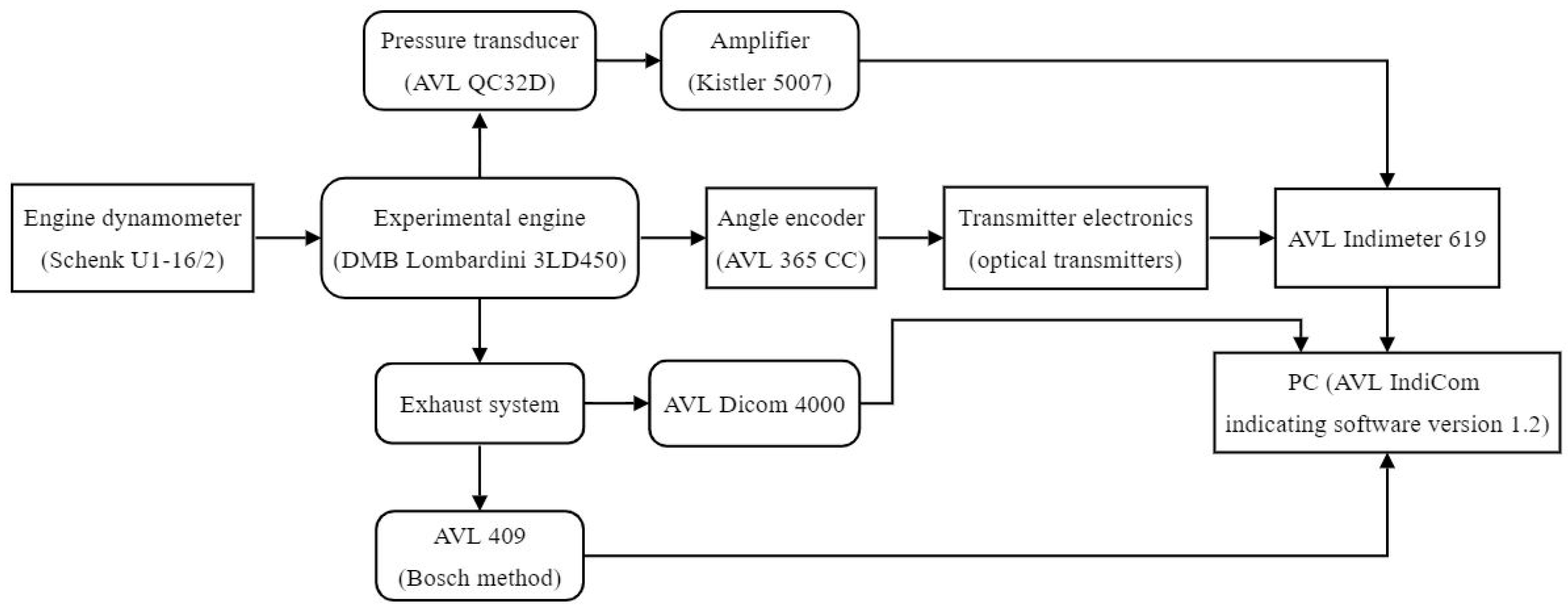
Figure 1. Single-cylinder test bench scheme—FIN KG.
Atmosphere 15 00184 g001
Figure 2. Fuel injector and a pressure transducer for measuring the cylinder pressure.
Atmosphere 15 00184 g002
Figure 3. (a) Applied aluminum cylinder and (b) cylinder liner sample used in tribology research.
Atmosphere 15 00184 g003
Figure 4. (a) Test bench with the reciprocating compressor and the mounted cylinder, which is the object of tribological research, and (b) block for simulating loads in the reciprocating compressor downstream line with the integrated automatic servo valve for automatic air pressure regulation.
Atmosphere 15 00184 g004
Figure 5. (a) Sample of the tested material on the tribometer test bench and (b) tribometer module.
Atmosphere 15 00184 g005
Figure 6. Changes in Tmax and Pmax under higher engine speed of 2325 rpm and full load of 0.55 MPa depending on CR values for (a) SOI = 14 cad BTDC and (b) SOI = 18.5 cad BTDC.
Atmosphere 15 00184 g006
Figure 7. Changes in smoke and PM emissions under full load of 0.55 MPa and middle engine speed of 1960 rpm depending on CR values for (a) SOI = 14 cad BTDC and (b) SOI = 18.5 cad BTDC and under higher engine speed of 2325 rpm for (c) SOI = 14 cad BTDC and (d) SOI = 18.5 cad BTDC.
Atmosphere 15 00184 g007
Figure 8. Relations between PM emission and BSFC vs. NOx emission for optimal SOI and CR values under a higher engine speed of 2325 rpm.
Atmosphere 15 00184 g008
Figure 9. Relations between PM and NOx emissions vs. CR value according to ESC emission cycle conditions under (a) SOI = 14 cad BTDC and (b) SOI = 18.5 cad BTDC.
Atmosphere 15 00184 g009
Figure 10. CR response under 25% load and 2325 rpm [80].
Atmosphere 15 00184 g010
Figure 11. Friction coefficient and penetration depth change depending on the sliding time, distance, and cycles at constant maximum load and sliding speed, 0.9 N and 0.015 m/s, (a) for the base material and (b) for the reinforcement.
Atmosphere 15 00184 g011
Figure 12. Optical micrographs of damaged material surfaces after the sliding test at constant load of 0.9 N and speed of 0.015 m/s conditions for (a) the base material and (b) the reinforcement.
Atmosphere 15 00184 g012
Figure 13. Optical micrographs of the tribometer counter body ball surface after testing the material at constant load of 0.9 N and speed of 0.015 m/s (a) for the cylinder base and (b) for reinforcement.
Atmosphere 15 00184 g013
Table 1. EU emission standards for HD diesel and gas engines under transient test conditions [49].
Stage/(Date)Emission Test CycleCONMHCCH4 aNOxPMPN
[gkW−1h−1][kW−1h−1]
Euro V/(2008.10)European Transient Cycle (ETC)4.00.551.12.00.03
Euro VI/(2013.01)World Harmonized Transient Cycle (WHTC)4.00.16 b0.50.460.016.0 × 1011
a Only for gas engines (Euro V for NG; Euro VI for NG and LPG). b Total hydrocarbons (THC) for diesel engines. - Nonmethane hydrocarbons (NMHC).
Table 2. PTI-PN National programs in the EU [49].
CountryEffective Date
Comments
PN TLV
(cm−3)
Applicability
Netherlands2023.01
Regulation IENW/BSK-2021/125046
1,000,000All diesel LD vehicles with wall-flow filters (Euro 3-6) and HD vehicles: Euro VI
Belgium2022.07
Agreement of the Flemish, Walloon, and Brussels regions, announced in 2021.04
1,000,000Diesel LD vehicles: Euro 5B-6
Germany2023.01
AU-Richtlinie, Verkehrsblatt nr. 8 of 2021.04. PN counter specification PTB-A 12.16
250,000Diesel vehicles: LD Euro 6 and HD Euro VI
Switzerland2023.01
Amendments to SR 741.437, announced in 2022.02
250,000 aAll diesel vehicles with wall-flow filters
a At high idle; alternative standard of 100,000 cm−3 at low idle.
Table 3. Scope of LEZ programs for individual regions [60,61].
Country of RegionLEZ Scope
BelgiumAll vehicles with four or more wheels (planned); retrofit options 1
DenmarkAll diesel-powered vehicles above 3500 kg; stickers required; retrofit options 1
GermanyAll vehicles with four wheels; stickers required; retrofit options 1
GreeceAll vehicles; vehicles over or under 2200 kg
ItalyAll vehicles, including mopeds and motorcycles
Italy/France, Mont Blanc tunnelLorries only; control at tunnel entry
NetherlandsLorries over 3500 kg-camera-enforced
SwedenAll heavy, diesel-powered trucks and buses; stickers required
UK, LondonVans and similar vehicles over 1205 kg unladen and vehicles over 3500 kg-camera-enforced; foreign vehicles need to register
UK outside LondonPublic service buses only; retrofit options 1
Czech RepublicLorries over 3500 kg or 6000 kg; stickers required
Austrian LEZsLorries over 3500 kg; stickers required; some retrofit options 1
1 Retrofit devices used in LEZs need to be certified. The certification is conducted at the country level, and most countries maintain a list of certified devices.
Table 4. Single-cylinder IC engine description.
DescriptionValues/Characteristics
Manufacturer/typeDMB Lombardini/3LD450
Engine configurationDiesel, four-stroke with air cooling and direct fuel injection
Valve trainTwo valves per cylinder, overhead camshaft (OHC)
Bore/stroke85/80 mm/mm
Cylinder volume454 cm3
Start of fuel injection18.5 cad BTDC 1
Compression ratio (-)17.5:1
Maximum power/engine speed 27.3 kW/3000 rpm
Maximum torque 328 Nm
Brake specific fuel consumption 3262
1 cad BTDC (crank angle degree before top, dead center). 2 Maximum power according to DIN 70020. 3 Values under maximum power.
Table 5. Applied pistons for the experimental engine used in this research.
Design 1Design 2Design 3Design 4
CR (-)12.1:113.8:115.2:117.5:1
Piston chamber volume (L)0.0330.0280.0240.020
Piston chamber diameter (mm)55504743
Image of pistons with combustion chamberAtmosphere 15 00184 i001
Table 6. Test bench equipment description.
MeasureReference
Cylinder pressureAVL QC32D (piezoelectric, water-cooled transducer)
Crank angle rotationAVL 365 CC (angle encoder)
Indicating pressure signal amplificationKistler 5007 (charge amplifier)
Exhaust emissionAVL Dicom 4000
SmokeAVL 409 (Bosch method)
Cylinder pressure processingAVL IndiCom Indicating Software version 1.2
(AVL List GmbH, Graz, Austria)
Data transferringAVL Indimeter 619
Load conditionsSchenk U1-16/2 (engine dynamometer)
Table 7. Experimental engine load conditions according to the ESC.
Load (%)BMEP (MPa)Fuel Mass per Cycle (mg∙Cycle−1)
150.0155
250.149
500.2812
750.4216
1000.5520
Disclaimer/Publisher’s Note: The statements, opinions and data contained in all publications are solely those of the individual author(s) and contributor(s) and not of MDPI and/or the editor(s). MDPI and/or the editor(s) disclaim responsibility for any injury to people or property resulting from any ideas, methods, instructions or products referred to in the content.