Article

3D Numerical Study of the Flow Properties in a Double-Spur Dikes Field during a Flood Process

State Key Laboratory of Hydraulics and Mountain River Engineering, Sichuan University, Chengdu 610065, China
*
Author to whom correspondence should be addressed.
Water 2018, 10(11), 1574; https://doi.org/10.3390/w10111574
Submission received: 4 October 2018 / Revised: 29 October 2018 / Accepted: 1 November 2018 / Published: 3 November 2018
(This article belongs to the Section Hydraulics and Hydrodynamics)

Abstract

:
A 3D numerical model is developed to study the flow characteristics of a double-spur dikes field on Yangtze River during a flood process, which was presented by the variation of the flow condition. The model is based on Navier–Stokes (NS) equations, the porous medium method (PMM) is employed to treat the solid structures including the river bed surface, the volume of fluid (VOF) method is applied to track the motion of the water surface during the flood process, and large eddy simulation (LES) is adopted to capture the turbulence transport and dissipation. Using this model, the target reach’s flow field before the construction of double-spur dikes is simulated first, while the numerical results are compared to the field measurements on flow velocity and water surface level, and fairly good agreements are shown. Then, the model is applied to reproduce the hydrodynamic evolution during a flood process after double-spur dikes’ constructions, while the detailed 3D flow fields are obtained under some certain states with different submergence rates of the spur dikes; finally, the potential damage positions around these spur dikes are analyzed accordingly.

1. Introduction

Spur dikes (also known as groynes) are one of the commonly used hydraulic structures in river engineering. The importance of the research on local flow field around spur dikes is significant, either to the development of fundamental hydrodynamic theory, or to the actual design and construction of river navigation, scour prevention and ecosystem preservation projects. Over the past century, groyne-related studies on some big rivers such as Mississippi River, Rhine River and Yellow River, have attracted the attention of many scholars and engineers, such as Bowles et al. [1], Shields [2], Ten Brinke et al. [3], Dong et al. [4], Jamieson et al. [5], Schloesser et al. [6], Braun et al. [7].
However, the complexity of the flow characteristics in these problems cannot be neglected. The constructions of spur dikes in navigable waterways will inevitably lead to the change of not only main flow patterns by narrowing the river width and increasing water depth, but also the local area close to the hydraulic structures, at which the flow separation and circumfluence result in strong 3D turbulence, while the pressure distribution is non-hydrostatic. Eventual balance is reached as flow and structures strongly couple with each other, which is not easy to correctly capture but essential for engineering applications. In particular, when submergence occurs during a flood process, the river stage continues increasing until the spur dikes’ tops are submerged under the water surface. The vertical flow structures as well the horizontal flow structures both contribute to the turbulence formation, and therefore the flow field becomes much more unpredictable.
All these aspects make the study of local flow fields around the spur dikes difficult and a longstanding challenge for hydraulic investigators. Therefore, the flume experiment was commonly adopted for most researchers especially in the early stages. Rajaratnam and Nwachukwu [8] conducted an experimental study on the turbulent flow near a thin-plate groyne, while some observations were also made on a groyne with a semi-cylindrical hose. Kuhnle and Alonso [9,10] did a series of flume experiments around a submerged trapezoidal spur dike with different flow conditions; the flow field and local scour were analyzed accordingly. Similar studies can also been found in other research (Duan et al., [11,12]; Kang and Ji et al., [13]; Kang and Yeo, [14]; Zhang et al., [15,16]; Uijttewaal, [17]).
Benefit from the generation of computer information technology and numerical techniques, numerical simulation has gradually become an effective way in this research area since the last decade of 20th century. For example, Tingsanchali and Matheswaran [18] used a 2D depth-averaged model which incorporated a correction factor of k-ε equations to calculate the distribution of bed-shear stress around the spur dikes. Mayerle et al. [19] used a 3D model in which the static pressure was assumed to study the relationship between the flow field and vortex behind the spur dikes. However, it can be found that most of these numerical model (Molls and Chaudhry et al., [20]; Ouillon and Dartus, [21]; Nagata and Hosoda et al., [22]) adopted Reynolds-average methods e.g., the k-ɛ turbulence model, which can be used to obtain the mean flow field but have problems in correctly reflecting the temporal fluctuations in theory, and therefore are not suitable for some dynamic equilibrium cases such as vortex shedding. In the present study, when the water level varies and the submergence may happen, this kind of model may not accurately reproduce the dynamic coupling process between the fluid and structures. Moreover, over-predictions of scour depths by these models have also been found by many investigators in the simulation of local scour around spur dikes (Peng et al., [23]; Zhang et al., [15]).
Fortunately, more and more advanced turbulence models such as the large eddy simulation (LES) model have been developed and improved in recent years, and they have achieved great success in engineering applications, which offers an alternative solution to the Reynolds-average methods’ short board. Therefore, some investigators started to introduce these models into the flow simulation around spur dikes. Yu and Tang et al. [24] adopted LES to simulate the 3D flow around a non-submerged spur dike and analysed the vortex downstream. McCoy et al. [25,26] studied the flow hydrodynamics in a straight open channel with series of spur dikes using LES and analyzed the mixing-layer eddies around the spur dike. Similar studies are also undertaken by Koken and Constantinescu [27,28,29] and Khosronejad et al. [30,31]. However, it is a pity that the majority of these works focus on simplified rectangle-shaped spur dikes cases under a single flow condition in experimental flumes, rather than the actual river cases with complex bed forms. To the best of our knowledge, no previous researchers have conducted studies on flow properties around multiple spur dikes field considering the variation of flow conditions in a real-world river, in which the spur dikes change from non-submerged to submerged.
Therefore, we illustrate an application of a 3D numerical model combined with the porous medium method (PMM) and LES scheme on an actual engineering case. This numerical platform named NEWTANK has already been successfully used on a variety of hydrodynamic cases for the past two decades (Lin and Li, [32]; Liu and Lin, [33,34]; Lin, [35]; Xue and Lin, [36]; Lin and Cheng et al., [37]). The introduction of PMM not only gives this model the capability to predict flow suction or injection through the porous bed, which is important for the model’s further development to accurately simulate the local scour, but also allows structures like spur dikes and the complex bed forms to be examined with the same numerical method as the rectangle mesh system, resulting in the procedure of model building being much more convenient.
In the present study, we introduced the model firstly, and then presented verification against field measurement of the target river reach before the double-spur dikes’ construction, afterwards, this model was applied to investigate the flow characteristics after the construction of double-spur dikes, in which the detailed 3D flow fields during their submergence processes along with the increasing water levels were obtained, while the potential damage positions around these spur dikes were analyzed accordingly for engineering purposes.

2. Numerical Methodology

2.1. Mathematical Formula

In the present model, the motion of incompressible fluid outside a porous domain is described by general Navier–Stokes (NS) equations in which turbulence is modeled by LES, while the flow motion within the porous medium is described by the modified Navier–Stokes equations, which are obtained by conducting a spatial average over a length scale larger than the typical pore size but smaller than the characteristic length scale of the physical problem (Lin and Karunarathna, [38,39]):
u ¯ i x i = 0  
1 n u ¯ i t + u ¯ j n 2 u ¯ i x j = 1 ρ p ¯ 0 x i + ν n 2 u ¯ i x j x j f ¯ i 1 n 2 u i u j ¯ x j  
where u ¯ i is the spatially averaged flow velocity in i direction, p0 is the effective pressure, ρ, ν and n are density, kinematic viscosity of fluid and effective porosity, respectively. The present model neglects the last term on the right hand side of Equation (2) with the assumption of negligible mean turbulence shear effect inside the porous medium. The force f ¯ i is caused by the presence of porous material, which includes inertia and drag forces f ¯ i = f ¯ I i + f ¯ D i . The inertia force represents the additional momentum required to accelerate water in the porous medium that is known as the added mass phenomenon, which can be obtained by summing up the contribution from each spherical particle and taking the average as Equation (3). The drag force can be derived in a similar way as Equation (4) by introducing the empirical formula of the drag coefficient for a single smooth sphere.
f ¯ I i = γ p ( 1 n ) n 2 u ¯ i t  
f ¯ D i = 3 4 C D ( 1 n ) n 3 1 d 50 u c u i ¯  
where γp is the virtual mass coefficient, and d50 is the mean diameter of particles, while u ¯ c is the characteristic velocity and CD is the drag force coefficient. More details about this method can be found in Lin and Karunarathna [38,39].
The concept of two-phase flow is introduced into this model. The three dimensional PLIC-VOF (piecewise linear interface calculation–volume of fluid) method (Gueyffier and Nadim et al., [40]) which originates from Youngs’ theory [41] is adopted to track the free surface motion. By introducing a volume of fluid function F = ( ρ ρ a ) / ( ρ w ρ a ) , the VOF transport equation can be written as:
F t + ( u i F ) x i = 0  
With the help of the VOF function, the density of fluid can be rewritten as ρ = F ρ w + ( 1 F ) ρ a . Where the subscript w and a mean water and air.
The LES is employed to capture turbulence transport and dissipation in this model. After being filtered by the spatial filter top-hat function, the sub-grid stress terms appear in the momentum equations, which can be modeled by the Smagorinsky sub-grid scale model (Smagorinsky, [42]):
τ i j 1 3 τ k k δ i j = 2 ρ ν t ( u ¯ i x j + u ¯ j x i )  
where ν t = C s Δ 2 | S ¯ | is the eddy viscosity, Cs is the Smagorinsky coefficient, Δ = Δ x Δ y Δ z 3 is the filter size calculated by control volume Δx, Δy and Δz. | S ¯ | = 2 S ¯ i j S ¯ i j is the filtered strain-rate tensor, and the expression for S ¯ i j is:
S ¯ i j = 1 2 ( u ¯ i x j + u ¯ j x i )  

2.2. Numerical Implementation

This numerical model is constructed on a non-uniform Cartesian coordinate system, while a staggered grid system is adopted. The scalars are defined at cell centers and vectors are defined at the centers of cell faces. The Navier–Stokes equations are solved by the two-step projection method (Liu and Lin, [33]). In the first step, the time derivative is discretized and an intermediate velocity is obtained, and then in the second step, the intermediate velocity field is projected onto a divergence-free plane to obtain the final velocity where the pressure is obtained by solving the Poisson equation. A combined upwind and central scheme is used to discretize the convection terms and a central difference scheme is used for the diffusion terms.
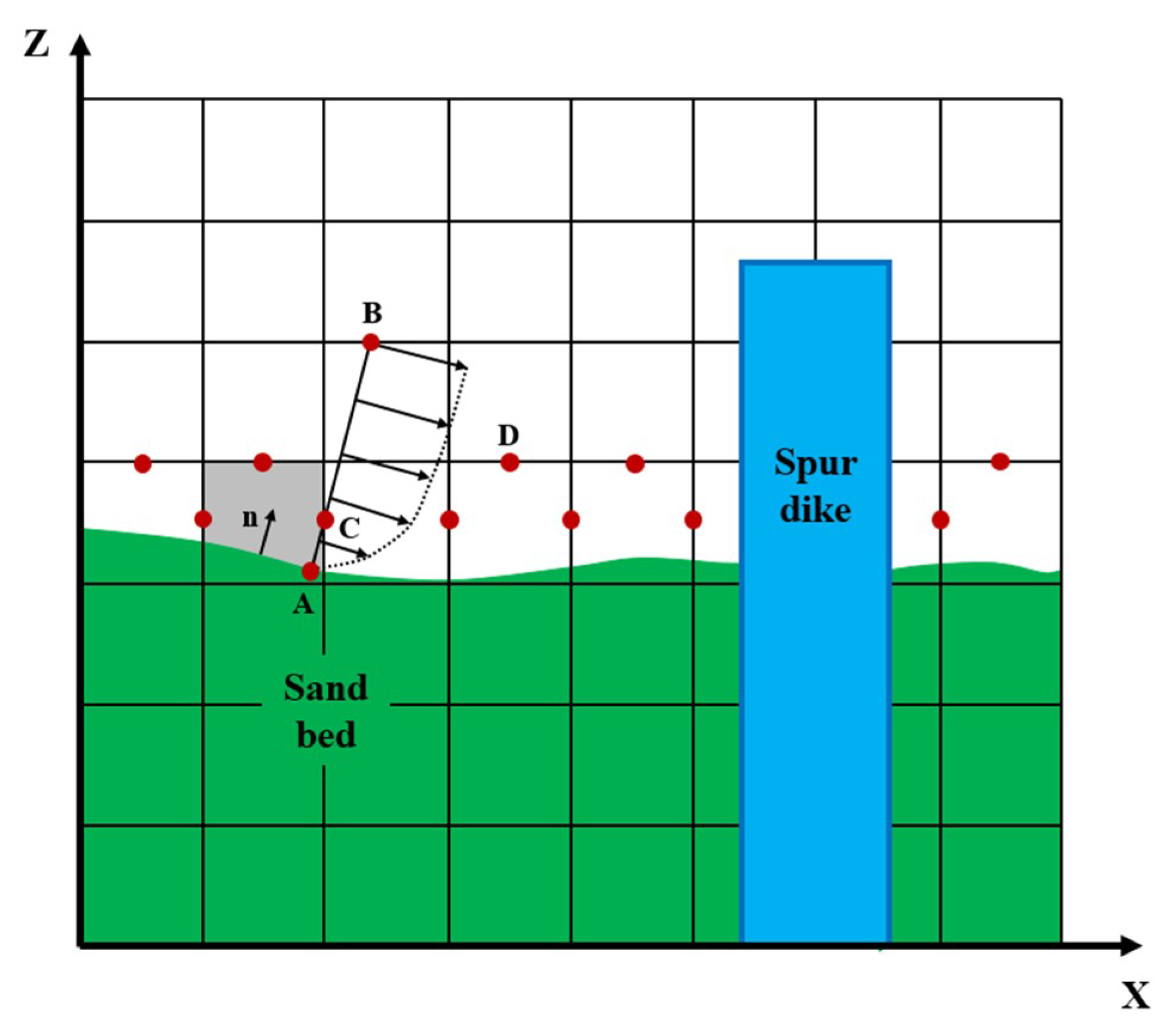
For the application of the PMM, all the cells are defined with different porosity based on what kind of medium each is (fluid nf, structure nd or river bed nb, ns, while nb defines the percentages that river bed takes in one cell and ns is the porosity of the sand bed) as Figure 1 shows:
In the computational process, the same wall function that Khosronejad et al. [30] adopted for their LES scheme model is applied to reconstruct the velocity components at the near wall nodes with the obtained velocity vector resolved by the governing equations:
u u = { y + y + y 0 + 1 κ ln ( E y + ) y + > y 0 +  
where y + = y u / ν is the non-dimensional distance from the wall boundary, y 0 + = 11.53 , and κ = 0.41 is the von Karman constant. E is roughness parameter related to the roughness Reynolds number.
Considering a cell marked in the gray color in Figure 2 and the normal vector of bed surface is n, the line paralleling with n passing through C point intersect the bed at point A point while intersecting the upper cell at point B. The velocity vector at point B tangential to the bed slope of gray cell can be obtained by distance-weighted interpolation among the nearby cells on which the flow velocity is solved by NS equations. With the help of the wall functions above, the friction velocity at point A can be calculated, then the shear stress is obtained, in the process of which, the velocity vector at point C can also be reconstructed for the momentum equations.
The model’s two stability criteria are dictated by Liu and Lin [33]. One is related to the convection process which is characterized by the Courant number (Cr) restriction, while the other stability restriction is related to the diffusion process.
Δ t min { C r × Δ x u max , C r × Δ y v max , C r × Δ z w max }  
Δ t min { ρ Δ x 2 6 ( μ + μ t ) , ρ Δ y 2 6 ( μ + μ t ) , ρ Δ z 2 6 ( μ + μ t ) }  
Therefore, the computational time step is automatically adjusted by these two criteria through whole numerical process, and the Courant number used in the present study is relatively strict 0.1. All the numerical cases are operated on a quad-core personal computer of 3.7 GHz along with 16 GB of RAM.

3. Field Measurement

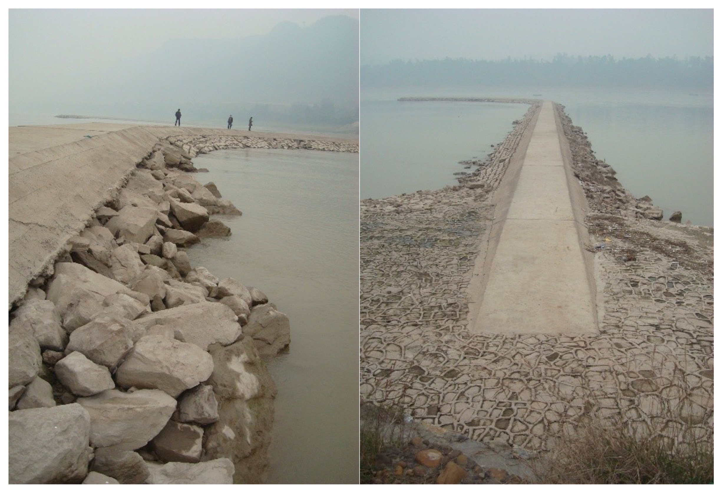
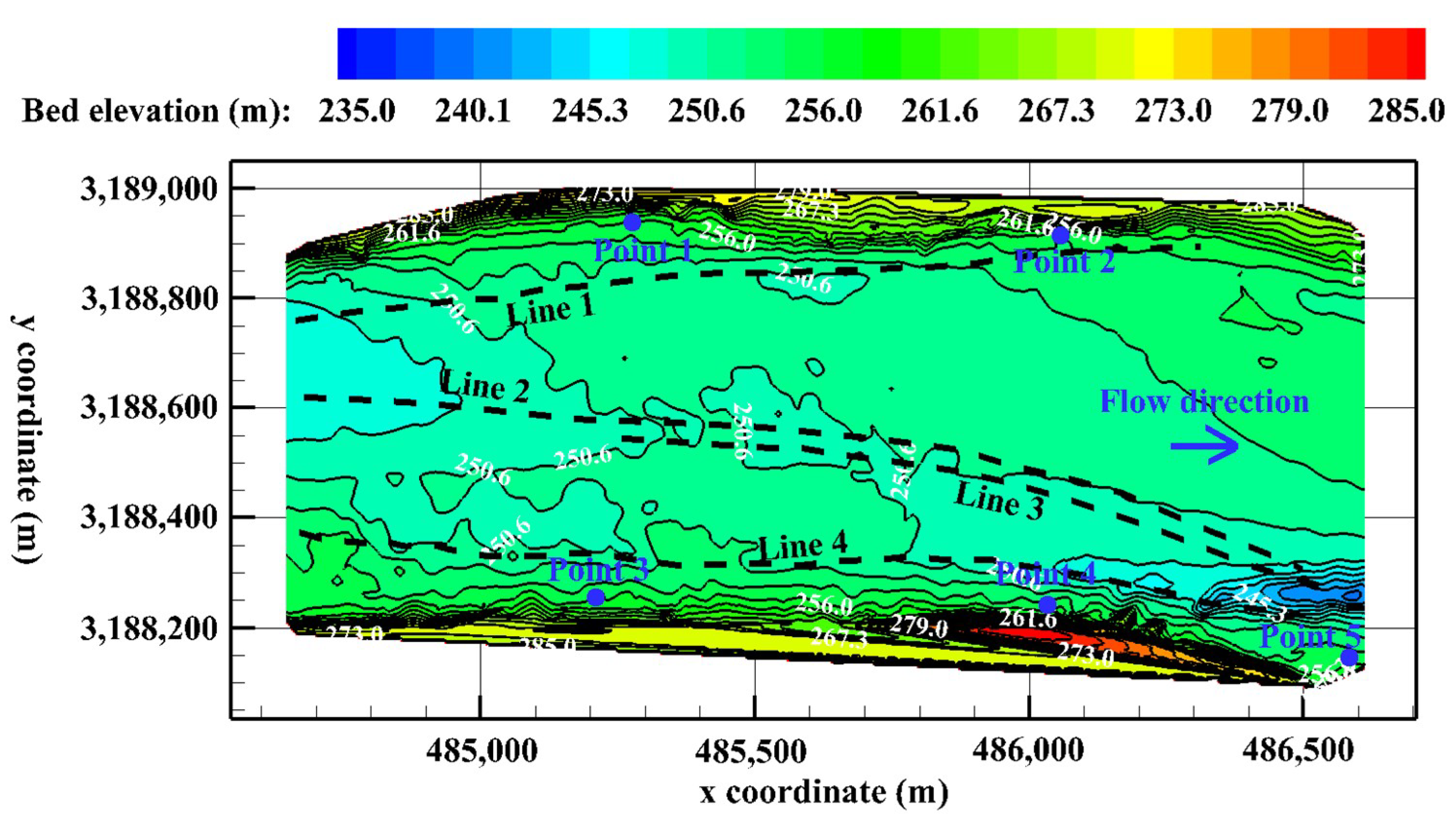
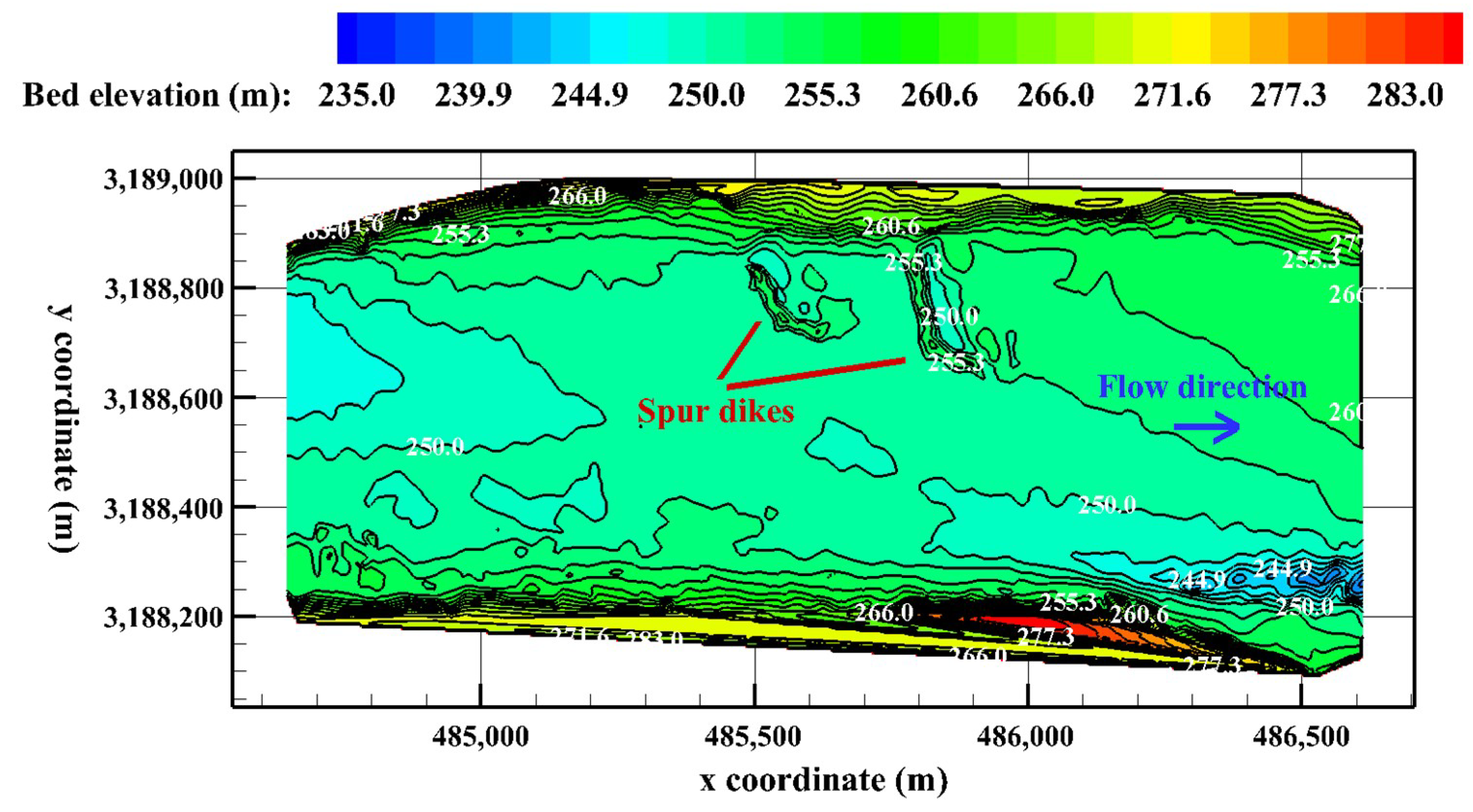
In this study, the Yangliuqi reach of the Yangtze River is selected, which is located at 1017.8 km of the navigation waterway between Hejiangmen, Yibin City and Naxi, Luzhou City. The reach is transitional shoal, and the channel bed consists of red sandstone covered by cobbles and boulders. The double spur dikes (Figure 3) were constructed on this reach in 2011, and therefore two different kinds of engineering cases are taken into consideration with the terrain contours from field measurement shown in Figure 4 and Figure 5.
One is the natural river case before the spur dikes’ construction (Case No.1), in which the surface flow velocity is measured by electronic tachometer with a float technique while the buoys move along four lines, and the water elevations are also observed at five different locations through reading water gauges. The positions of the four lines and five locations are plotted in Figure 4 with black and blue colors, respectively. In this case, the flow discharge of the reach inlet and the water levels of the reach outlet are both measured for the numerical modeling.
The other one is the double-spur dikes case about one year after the spur dikes’ construction (Case No.2), in which the flow discharge of the reach inlet and the water levels of the reach outlet are measured, as well as the terrain contours. From Figure 5, the double spur dikes built at the left bank around the middle position of the reach can be seen clearly. All the flow conditions in above two cases are summarized and listed in Table 1.

4. Model Verification

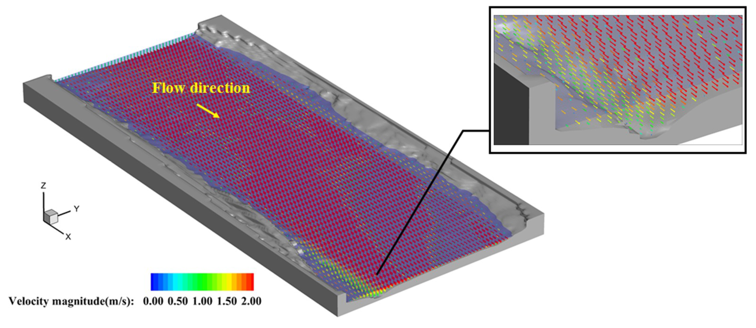
Since the flow velocity and water elevations are observed in the natural river case (Case No.1), numerical verification is conducted accordingly. The computational domain of x and y directions are totally the same as the target reach in Figure 4, while the z direction is from 235 m to 295 m. The non-uniform grid system is used, while the cell numbers in three directions are 500, 150 and 220 respectively. In the x and y directions, the mesh is refined at the vicinity of spur dikes and stretch to the channel inlet and outlet, resulting in minimum grid sizes of 0.8 m and 1.2 m in these two directions. The domain in the z direction is divided into two regions separated by z = 252 m, from which the grid spacing stretches to the domain top and bottom, resulting in a minimum grid size of 2 cm. The unit-width flow discharge of the reach inlet and the water elevation of the reach outlet interpolated from the field measurement are taken as the boundary conditions for the numerical run. Total computational time is 5000 s and the time step is automatically adjusted according to the stability criteria mentioned before. The flow field of the target reach in the dynamic equilibrium state is shown in Figure 6. The blue translucent contour represents the water surface and the gray non-transparent contour is the bed surface, while the vectors show flow velocity and their colors depend on the velocity magnitude.
To check grid dependence, another numerical case of a more refined mesh system with cell numbers being 600, 200 and 250 is also conducted, using a similar mesh scheme, resulting in a minimum grid size of 1.5 cm in the z direction. Using a personal computer, the numerical cases with coarse mesh and refined mesh require 4 days and 9 days respectively.
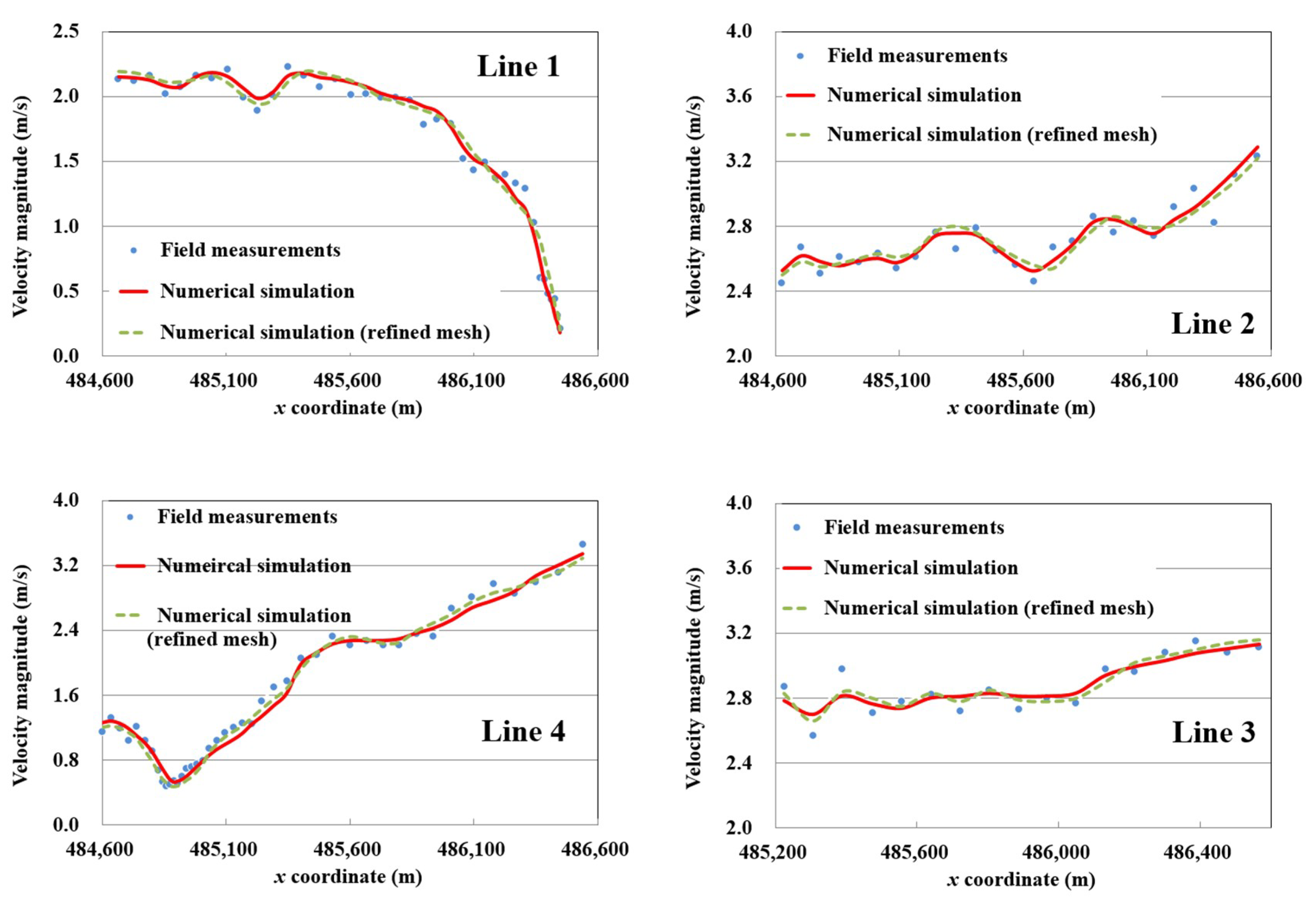
After the dynamic equilibrium state is obtained, 200 s time-average windows were conducted for the numerical results; then, the velocity magnitudes along four lines and water elevations at five selected points are compared to the measurement data in Figure 7 and Table 2. From this it can be concluded that the performance of this model is essentially invariant under the two different mesh systems, suggesting this model can accurately reproduce the flow field and the variation of water surface under the specified flow condition, and that good agreement can be obtained in comparison with field measurement, while the relative errors of the flow velocity and water elevation are less than 9.6% and 9.9% for the coarse mesh, and 9.9% and 11.7% for the refined mesh, respectively (dimensionless by water depth).

5. Results and Discussion

Being validated by the above natural river case (Case No.1), this model is applied to the double-spur dikes case (Case No.2) after their construction with the previous coarse mesh system. The terrain contours in Figure 5 is employed, while the computational domain is totally the same as the natural river case, as well as the cell numbers in three directions. The computational time is 10,800 s and the time step is also automatically adjusted.
The flow discharge and water elevation of Case No.2 in Table 1 are taken as the initial flood conditions. After obtaining the equilibrium state under this condition, the flow field of the target reach is shown in Figure 8 and Figure 9. It can be found that the flow velocity of the main flow is much larger than that of the circumfluence zone behind the spur dikes, which is mainly due to the shelter effect of the structures. The double-spur dikes narrowed the river flow width and induced water to move along the main navigation channel, which makes the reach more navigable. Under this flood condition, the double-spur dikes’ tops are still above the water level, and therefore this is called the “non-submerged condition”.
As the flow depth increases during a whole flood process, these two spur dikes will be submerged underwater, in which condition the flow fields around the structures change a lot and the flow structure is very different from the non-submerged case mentioned above. This process is implemented by gradually increasing the water level and flow discharge until they obtain the same value as the Case No.1 in Table 1 (flow discharge equals 6270 m3/s and the mean value of water level equals 256.2 m). After achieving this flow condition with a larger flow discharge and higher water level, both of the spur dikes are totally submerged under the water surface, which is defined as “submerged condition” or “totally submerged condition”.
During the process from the “non-submerged condition” getting to the “submerged condition”, there is a certain state when portions of the spur dikes are submerged to a shallow degree under the water surface while other portions are still above the water, which is defined as the “shallow submerged condition”.
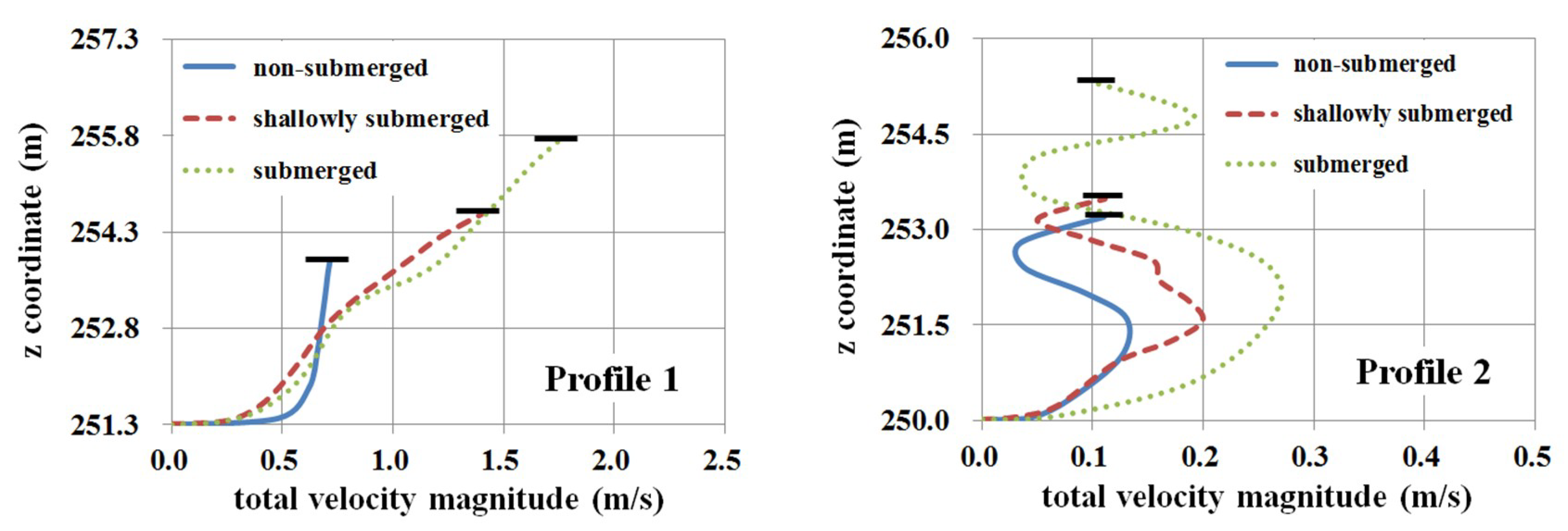
To better understand the local flow characteristics around the spur dikes during the whole flood process, six spots are selected (Figure 9), on which the vertical velocity profiles of these three conditions are extracted from flow field data and plotted in Figure 10. Differences can be found between these velocity profiles temporally and spatially, which proves again the flow separation and circumfluence result in strong 3D turbulence around these spur dikes. Compared to the vertical velocity profiles in “non-submerged condition”, the overtopping flow in “shallow submerged condition” makes the vertical velocity profiles begin to show the shape of double crests, which can be seen clearly in Profile 1, Profile 4 and Profile 5. When the “submerged condition” is obtained, we can find that at the locations of Profile 2 and Profile 5, which are very close to these spur dikes, the velocity magnitudes at the upper region of the whole flow depth have already achieved relatively large values due to the overtopping flow, and their values are comparable to or even larger than those of the bottom region caused by the circumfluence vortex.
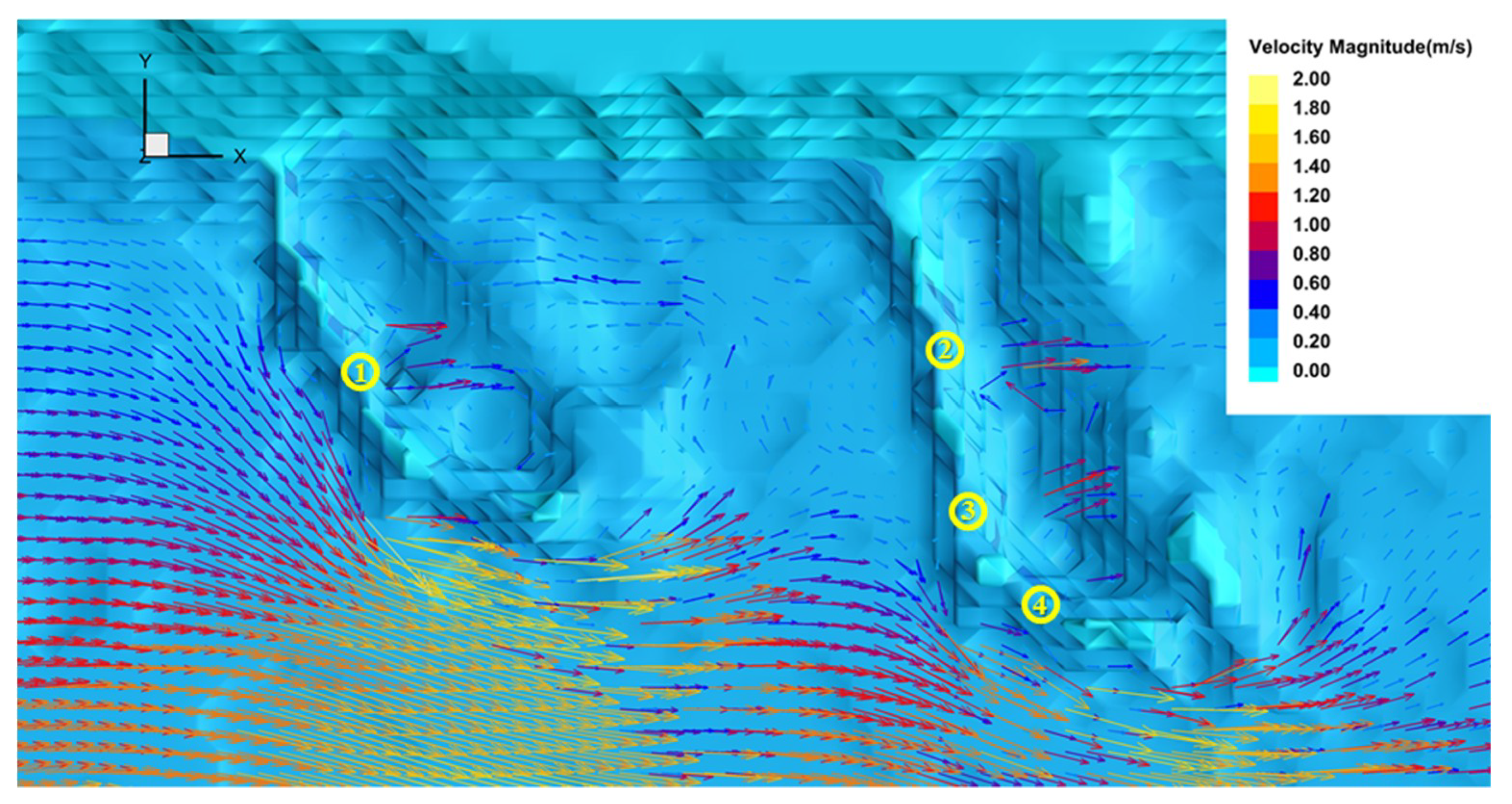
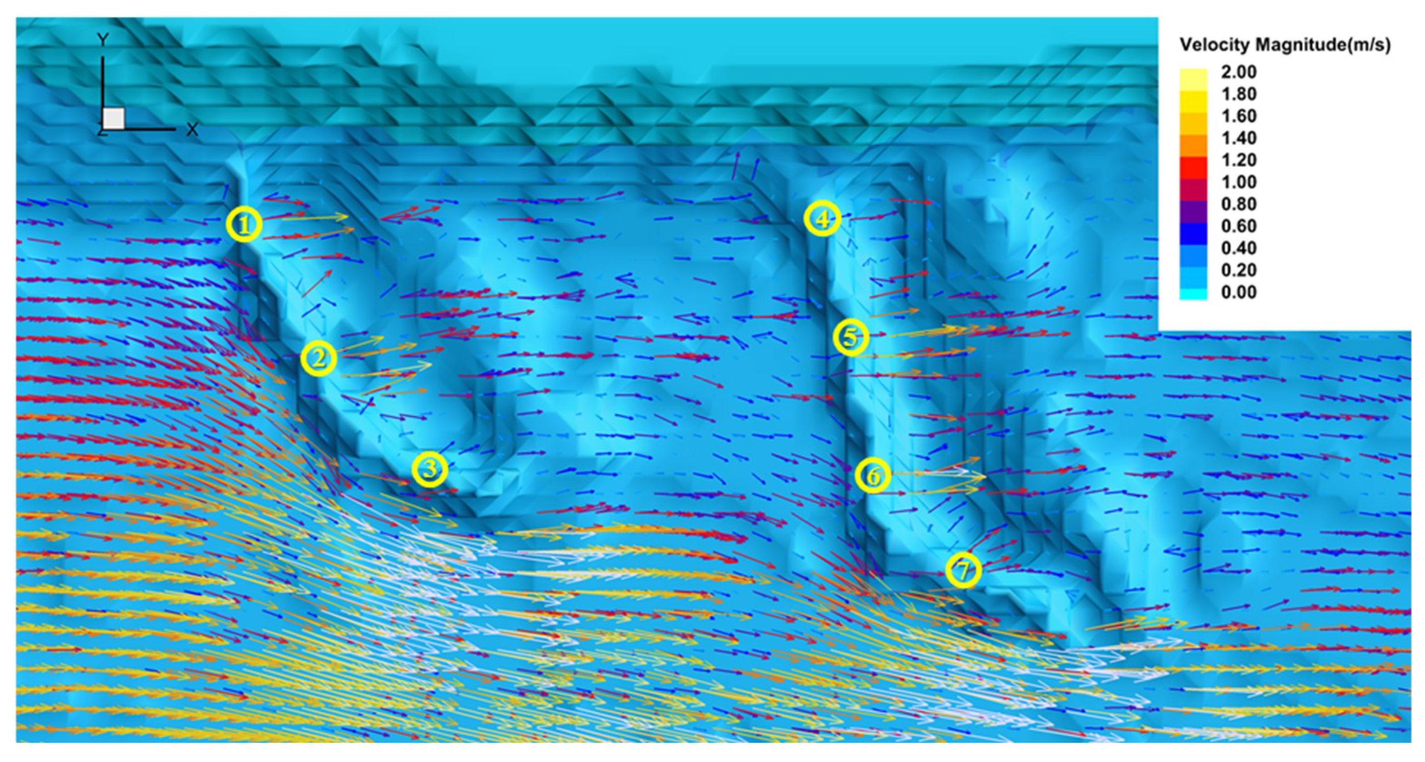
According to the field observation and corresponding flume test of the target reach (Jia and She et al., [43]), the double-spur dikes are vulnerable in the “shallow submerged condition” and “submerged condition”, and the phenomena of collapse always show, which are directly caused by the intensive overtopping flow. To find the potential damage positions and offer guidance for engineering reinforcement, the 3D flow fields of these two conditions are plotted in Figure 11 and Figure 12, and the depth-averaged velocity magnitude of the overtopping flow is calculated. The positions with relatively large values in these two figures are highlighted with numbered yellow circles, which are also listed with their velocity magnitudes in Table 3 and Table 4.
In Figure 11 and Table 3, the overtopping velocity magnitudes at the four locations are 0.85 m/s, 0.96 m/s, 0.92 m/s and 0.73 m/s respectively, while continued scouring starting from small sediment particles with relatively low threshold velocity may occur and cause damage to the solid structures; therefore, extra engineering reinforcement should be conducted. When the “submerged condition” is obtained, the double spur dikes are both submerged totally under the water. In Figure 12 and Table 4, the overtopping flow has relatively large value at more positions. The seven yellow circles point out the positions that structural damage may occur easily.

6. Conclusions

In this study, a three-dimensional numerical model based on Navier–Stokes equations which can predict flow motion accurately is developed and applied to the simulation of a local flow field under a flood process around double-spur dikes constructed on an actual river. The employment of a LES turbulence model makes it have the capability to capture the variation of flow field as the flow depth changes and submergence occurs, which can provide lots of useful information for the design and construction of hydraulic structures, as well as damage protection in engineering applications. The adoption of the porous medium method (PMM) enables this model to be conducted on a Cartesian coordinate system, resulting in a relatively easy modeling process. The good agreement of the verification case implies that this model can be applied to further engineering practices on structure–fluid interaction.
The simulation of the double-spur dikes case indicates that before submergence happens, the flow velocity of the main flow is much larger than the local area of the spur dike due to the shelter effect of the structures, while the spur dikes’ constructions narrow the river flow width and induce the water to move along the main navigation channel, making the river reach more navigable. As the flood stage increases, submergence should be taken into consideration, at the state that portions of the spur dikes are submerged to a shallow degree under the water surface while other portions are still above it; the overtopping flow may start to cause scouring and damage to the solid structures. Then, while the spur dikes are totally submerged, more positions around the double-spur dike field face danger to their engineering application. The locations that need extra engineering reinforcement in different submergence states vary a lot in terms of space.

Author Contributions

Conceptualization, P.L.; Methodology, P.L., X.H.; Validation, X.H.; Data Curation, X.H.; Writing-Original Draft Preparation, X.H.; Visualization, X.H.; Supervision, P.L.; Funding Acquisition, P.L.

Funding

This research was funded by the Chongqing Waterway Bureau of Yangtze River (Grant number: No. 10H1305).

Conflicts of Interest

The authors declare no conflict of interest.

References

  1. Bowles, R.E.; Pennington, C.H.; Howell, F.G. Macroinvertebrate drift associated with a dike field in the lower Mississippi River. Am. Zool. 1983, 23, 1003. [Google Scholar]
  2. Shields, F.D. Fate of lower Mississippi River habitats associated with river training dikes. Aquat. Conserv. 1995, 5, 97–108. [Google Scholar] [CrossRef]
  3. Ten Brinke, W.B.M.; Schulze, F.H.; van der Veer, P. Sand exchange between groyne-field beaches and the navigation channel of the Dutch Rhine: The impact of navigation versus river flow. River Res. Appl. 2004, 20, 899–928. [Google Scholar] [CrossRef]
  4. Dong, N.H.; Zhao, X.J.; Liu, Y. Experimental study on characteristics of sediment scouring and deposition in dike-narrowed river channel of Lower Yellow River. J. Hydraul. Eng. 2009, 40, 688–695. (In Chinese) [Google Scholar]
  5. Jamieson, E.C.; Rennie, C.D. 3-D flow and scour near a submerged wing dike: ADCP measurements on the Missouri River. Water Resour. Res. 2011, 47, W07544. [Google Scholar] [CrossRef]
  6. Schloesser, J.T.; Paukert, C.P.; Doyle, W.J. Fish assemblages at engineered and natural channel structures in the lower Missouri River: Implications for modified dike structures. River Res. Appl. 2012, 28, 1695–1707. [Google Scholar] [CrossRef]
  7. Braun, A.P.; Sobotka, M.J.; Phelps, Q.E. Fish Associations among Un-notched, Notched and L-head Dikes in the Middle Mississippi River. River Res. Appl. 2016, 32, 804–811. [Google Scholar] [CrossRef]
  8. Rajaratnam, N.; Nwachukwu, B.A. Flow near groin-like structures. J. Hydraul. Eng. 1983, 109, 463–480. [Google Scholar] [CrossRef]
  9. Kuhnle, R.A.; Alonso, C.V.; Shields, F.D., Jr. Geometry of scour holes associated with 90° spur dikes. J. Hydraul. Eng. 1999, 125, 972–978. [Google Scholar] [CrossRef]
  10. Kuhnle, R.; Jia, Y.; Shields, F.D., Jr. Local Scour Associated with Angled Spur Dikes. J. Hydraul. Eng. 2002, 128, 1087–1093. [Google Scholar] [CrossRef]
  11. Duan, J.G. Mean flow and turbulence around a laboratory spur dike. J. Hydraul. Eng. 2009, 135, 803–811. [Google Scholar] [CrossRef]
  12. Duan, J.G.; He, L.; Wang, G.Q.; Fu, X.D. Mean flow and turbulence around experimental spur dike. Adv. Water Resour. 2009, 32, 1717–1725. [Google Scholar] [CrossRef]
  13. Kang, J.G.; Yeo, H.K.; Kim, S.J.; Ji, U. Permeability effects of single groin on flow characteristics. J. Hydraul. Res. 2011, 49, 728–735. [Google Scholar] [CrossRef]
  14. Kang, J.G.; Yeo, H.K. Experimental study on the flow characteristics of L-type groyne. Engineering 2011, 3, 1002–1011. [Google Scholar] [CrossRef]
  15. Zhang, H. Study on Flow and Bed Evolution in Channels with Spur Dykes. Ph.D. Thesis, Kyoto University, Kyoto, Japan, 2005. [Google Scholar]
  16. Zhang, H.; Nakagawa, H.; Mizutani, H. Bed morphology and grain size characteristics around a spur dyke. Int. J. Sediment Res. 2012, 27, 141–157. [Google Scholar] [CrossRef]
  17. Uijttewaal, W.S.J. Effects of groyne layout on the flow in groyne fields: Laboratory experiments. J. Hydraul. Eng. 2005, 131, 782–791. [Google Scholar] [CrossRef]
  18. Tingsanchali, T.; Maheswaran, S. 2-D depth-average flow computation near groyne. J. Hydraul. Eng. 1990, 116, 71–86. [Google Scholar] [CrossRef]
  19. Mayerle, R.; Toro, F.M.; Wang, S.S.Y. Verification of a three-dimensional numerical model simulation of the flow in the vicinity of spur dikes. J. Hydraul. Res. 1995, 33, 243–256. [Google Scholar] [CrossRef]
  20. Molls, T.; Chaudhry, M.H.; Khan, K.W. Numerical simulation of two–dimensional flow near a spur dike. Adv. Water Resour. 1995, 118, 227–236. [Google Scholar] [CrossRef]
  21. Ouillon, S.; Dartus, D. Three-dimensional computation of flow around groyne. J. Hydraul. Eng. 1997, 123, 962–970. [Google Scholar] [CrossRef]
  22. Nagata, N.; Hosoda, T.; Nakato, T.; Muramoto, Y. Three-dimensional numerical model for flow and bed deformation around river hydraulic structures. J. Hydraul. Eng. 2005, 131, 1074–1087. [Google Scholar] [CrossRef]
  23. Peng, J. Three-Dimensional Flow Structure and Local Scour Around Spur Dikes. Ph.D. Thesis, University of Tokyo, Tokyo, Japan, 1998. [Google Scholar]
  24. Yu, X.; Tang, X.L.; Wang, W.C.; Wang, F.J.; Chen, Z.C.; Shi, X.Y. A lattice Boltzmann model coupled with a Large Eddy Simulation model for flows around a groyne. Int. J. Sediment Res. 2010, 25, 271–282. [Google Scholar] [CrossRef]
  25. McCoy, A.; Constantinescu, S.G.; Weber, L. A numerical investigation of the dynamics of coherent structures and mass exchange processes in a channel flow with two lateral submerged groynes. Water Resour. Res. 2007, 43, W05445. [Google Scholar] [CrossRef]
  26. McCoy, A.; Constantinescu, S.G.; Weber, L. Numerical investigation of flow hydrodynamics in a channel with series of groynes. J. Hydraul. Eng. 2008, 134, 157–172. [Google Scholar] [CrossRef]
  27. Koken, M.; Constantinescu, G. An investigation of the flow and scour mechanisms around isolated spur dikes in a shallow open channel: 1. Conditions corresponding to the initiation of the erosion and deposition process. Water Resour. Res. 2008, 44, W08406. [Google Scholar] [CrossRef]
  28. Koken, M.; Constantinescu, G. An investigation of the flow and scour mechanisms around isolated spur dikes in a shallow open channel: 2. Conditions corresponding to the final stages of the erosion and deposition process. Water Resour. Res. 2008, 44, W08407. [Google Scholar] [CrossRef]
  29. Koken, M.; Constantinescu, G. Flow and turbulence structure around a spur dike in a channel with a large scour hole. Water Resour. Res. 2011, 47, W12511. [Google Scholar] [CrossRef]
  30. Khosronejad, A.; Hill, C.; Kang, S.; Sotiropoulos, F. Computational and experimental investigation of scour past laboratory models of stream restoration rock structures. Adv. Water Resour. 2013, 1, 191–207. [Google Scholar] [CrossRef]
  31. Khosronejad, A.; Kozarek, J.L.; Palmsten, M.L.; Sotiropoulos, F. Numerical simulation of large dunes in meandering streams and rivers with in-stream rock structures. Adv. Water Resour. 2014, 9, 309–332. [Google Scholar] [CrossRef]
  32. Lin, P.; Li, C.W. Wave-current interaction with a vertical square cylinder. Ocean. Eng. 2003, 30, 55–76. [Google Scholar] [CrossRef]
  33. Liu, D.; Lin, P. A numerical study of three-dimensional liquid sloshing in tanks. J. Comput. Phys. 2008, 227, 3921–3939. [Google Scholar] [CrossRef]
  34. Liu, D.; Lin, P. Three-dimensional liquid sloshing in a tank with baffles. Ocean. Eng. 2009, 36, 202–212. [Google Scholar] [CrossRef]
  35. Lin, P. Numerical Modeling of Water Waves, 1st ed.; Taylor &Francis: London, UK; New York, NY, USA, 2008. [Google Scholar]
  36. Xue, M.; Lin, P. Numerical study of ring baffle effects on reducing violent liquid sloshing. Comput. Fluids 2011, 52, 116–129. [Google Scholar] [CrossRef]
  37. Lin, P.; Cheng, L.; Liu, D. A two-phase flow model for wave–structure interaction using a virtual boundary force method. Comput. Fluids 2016, 129, 101–110. [Google Scholar] [CrossRef]
  38. Karunarathna, S.A.S.A.; Lin, P. Numerical simulation of wave damping over porous Seabeds. Coast. Eng. 2006, 53, 845–855. [Google Scholar] [CrossRef]
  39. Lin, P.; Karunarathna, S.A.S.A. Numerical study of solitary wave interaction with porous breakwaters. J. Waterw. Port C 2007, 133, 352–363. [Google Scholar] [CrossRef]
  40. Gueyffier, D.; Li, J.; Nadim, A.; Scardovelli, R.; Zaleski, S. Volume-of-fluid interface tracking with smoothed surface stress methods for three-dimensional flows. J. Comput. Phys. 1999, 152, 423–456. [Google Scholar] [CrossRef]
  41. Youngs, D.L. Time-dependent multi-material flow with large fluid distortion. Numer. Methods Fluid Dyn. 1982, 24, 273–285. [Google Scholar]
  42. Smagorinsky, J.S. General circulation experiments with the primitive equations—1, the basic experiment. Mon. Weather Rev. 1963, 91, 99–164. [Google Scholar] [CrossRef]
  43. Jia, G.; She, J.; Wang, T.; Zhang, G. PIV measurement of flow structure behind submerged spur dike. Int. J. Hydroelectr. Energy 2012, 30, 84–86. (In Chinese) [Google Scholar]
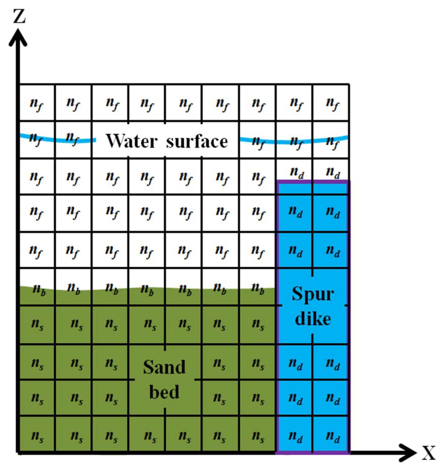
Figure 1. Porosity definition in the computational domain.
Water 10 01574 g001
Figure 2. Implement of the wall functions in this model.
Water 10 01574 g002
Figure 3. The double-spur dikes constructed on the target reach.
Water 10 01574 g003
Figure 4. Terrain contours of the target reach before the spur dikes’ construction (the datum is the sea level, and gray dashed lines and blue dots show the locations of flow velocity and water elevations being observed).
Water 10 01574 g004
Figure 5. Terrain contours of the target reach after the spur dikes’ construction (the datum is the sea level, and the double spur dikes were built at the left bank around the middle position of the reach).
Water 10 01574 g005
Figure 6. The numerical results on 3D flow field of the target reach in Case No.1.
Water 10 01574 g006
Figure 7. Comparison on the flow surface velocity in Case No.1.
Water 10 01574 g007
Figure 8. The numerical results on 3D flow field of the double-spur dikes case under non-submerged flood conditions (figure at bottom right shows the local flow field around the spur dikes with top view).
Water 10 01574 g008
Figure 9. Locations of the selected velocity profiles.
Water 10 01574 g009
Figure 10. Vertical velocity profiles of the six selected locations for three different flood stages around the double-spur dikes.
Water 10 01574 g010aWater 10 01574 g010b
Figure 11. Potential damage positions around the double spur dikes in shallow submerged condition (top view with 3D flow field).
Water 10 01574 g011
Figure 12. Potential damage positions around the double-spur dikes in totally submerged condition (top view with 3D flow field).
Water 10 01574 g012
Table 1. Flow conditions observed in field measurement for the two cases.
Case No.Total Flow Discharge (m3/s)Mean Water Elevation of Reach Outlet (m)
No.16270256.2
No.23120253.6
Table 2. Comparison on the water elevations in Case No.1.
Point No.Field Measurement
(m)
Numerical Results with Coarse Mesh
(m)
Numerical Results with Fine Mesh
(m)
Bed Elevation
(m)
Relative Error with Coarse MeshRelative Error with Refined Mesh
1256.76256.88256.82255.509.5%4.8%
2256.48256.54256.55255.606.8%8.0%
3256.80256.72256.70255.808.0%10.0%
4256.31256.20256.18255.209.9%11.7%
5255.86255.95255.91254.808.5%4.7%
Table 3. Flow velocity at the potential damage positions in shallow submerged condition.
Location No.Depth-Averaged Flow Velocity (m/s)Positions (x, y)
10.85485,531 m, 3,188,792 m
20.96485,808 m, 3,188,806 m
30.92485,820 m, 3,188,733 m
40.73485,853 m, 3,188,681 m
Table 4. Flow velocity at the potential damage positions in totally submerged condition.
Location No.Depth-Averaged Flow Velocity (m/s)Positions (x, y)
11.42485,496 m, 3,188,865 m
21.23485,534 m, 3,188,796 m
30.78485,587 m, 3,188,743 m
41.09485,792 m, 3,188,864 m
51.65485,807 m, 3,188,804 m
61.82485,817 m, 3,188,731 m
71.12485,859 m, 3,188,697 m