Article

Tsunami Intrusion and River Ice Movement

1
Ocean College, Zhejiang University, Hangzhou 310058, China
2
Department of Civil and Environmental Engineering, Clarkson University; Potsdam, NY 13699, USA
*
Author to whom correspondence should be addressed.
Water 2019, 11(6), 1290; https://doi.org/10.3390/w11061290
Submission received: 28 May 2019 / Revised: 12 June 2019 / Accepted: 17 June 2019 / Published: 20 June 2019
(This article belongs to the Section Hydraulics and Hydrodynamics)

Abstract

:
A two-dimensional wave model coupled with ice dynamics is developed to evaluate ice effects on shallow water wave propagation on a beach and in a channel. The nonlinear Boussinesq equations with ice effects are derived and solved by the hybrid technique of the Godunov-type finite volume method and finite difference method with the third-order Runge–Kutta method for time integration. The shock capturing method enables the model to simulate complex flows over irregular topography. The model is capable of simulating wave propagations accurately, including non-hydrostatic water pressure and wave dispersions. The ice dynamic module utilizes a Lagrangian discrete parcel method, based on smoothed particle hydrodynamics. The Boussinesq wave model is validated with an analytical solution of water surface oscillation in a parabolic container, an analytical solitary wave propagation in a flat channel, and experimental data on tsunami wave propagations. The validated model is then applied to investigate the interaction between ice and tsunami wave propagation, in terms of ice attenuation on tsunami wave propagations over a beach, ice deposition on the beach driven by the tsunami wave, and ice jam formation and release in a coastal channel with the intrusion of the tsunami wave. The simulated results demonstrated the interactions between tsunami waves and surface ice, including the maximum run up, ice movement along the beach, and ice jamming in a channel.

1. Introduction

Nonlinear shallow water wave equations are commonly used in global tsunami wave simulations and forecasting. However, they only account for nonlinear properties of the wave and neglect dispersions, which are essential in wave transformation in shallow water. Boussinesq-type equations (BE) considering non-hydrostatic water pressure and wave dispersions are commonly used by coastal engineers.
The classical, standard BE applies for weakly nonlinear and weakly dispersive waves, which was derived in terms of integrated horizontal velocities with linear dispersions. It is restricted to shallow waters with k H < 0.75 , where k is the wavenumber and H is the water depth [1]. By including higher order terms and more accurate vertical velocity distributions, the BE has been improved so that the linear dispersion can be extended to deep water conditions [2,3,4,5,6,7,8,9,10]. Recently, new forms of BE have been developed with higher-order accuracy, which extends the applicability ranging from shallow to deep waters [11,12]. BE is usually modified by adding dissipation terms or the artificial viscosity in momentum equations to account for energy dissipation of wave breaking in the surf zone [13].
The extreme weather might significantly affect wave patterns, flow conditions, sediment transport, and bathymetric changes in coastal region-related climate changes [14,15,16]. The tsunami wave, as an example, was found to interact with sea ice flexure and trigger the Sulzberger Ice Shelf calving in the Honshu earthquake that occurred on 11 March 2011 [17]. The Honshu tsunami wave produced wave run-up heights of 5 m and structure damages from the floating sea ice with thickness of about 0.3 m in the Kuril Islands were observed [18]. Although a tsunami accompanied by floating ice is destructive, the interaction between tsunami wave propagation and floating ice movement has not been quantitatively studied. However, significant progress has been made in ice dynamic studies, especially in terms of mathematical modeling. Shen et al. [19] developed a one-dimensional river ice model to examine the leading-edge propagation for ice jam and potential flooding risks. Later, the two-dimensional ice dynamic model was developed to explore the interactions between unsteady flows and ice movement [20,21,22,23]. Such techniques contributed to the understanding of ice jamming formation and release, and ice cover breakup [20,21,22,23].
In the literature, the BE is rarely applied to investigate wave propagations with ice effects, while the ice dynamic models have not been coupled with the tsunami wave. The main objective of this study is to investigate the interaction between surface ice transport and tsunami wave propagation. This paper first proposes a two-dimensional Boussinesq wave model that is coupled with ice dynamics. Then, the model is validated with analytical solutions for oscillatory flows, theoretical solitary wave, and an experimental tsunami wave. The model is finally applied to simulate tsunami wave propagation with ice, including surface ice transport over a beach, ice deposition on the beach, and ice jam in a coastal channel. Model results showed that surface ice can significantly affect wave propagations along the beach and tsunami waves and vice versa.

2. Model Formulation

A two-dimensional Boussinesq wave model is coupled with the ice dynamic model to study the interactions between ice movement and tsunami wave propagation. The wave model is solved first with given surface ice thickness, areal ice concentration, and ice velocity, based on the extended Boussinesq equations considering ice mass and ice frictions on the flow dynamic. At each coupling time (every 10 min, for example), hydrodynamic parameters, including flow velocity fields, and water surface elevations solved from the wave model are passed to the ice dynamic model. Then, the ice model calculates the ice movement in the coupling time with the given flow velocity and water surface level. Afterward, the calculated ice thickness, concentration, and ice velocity are fed back to the wave model to consider ice influence on mass and momentum conservations. Such processes are repeated until the simulation is completed. Since the smoothed particle hydrodynamic is used to solve the ice dynamics, the ice properties in the Lagrangian field is interpolated to the Eulerian flow field, using the inverse distance weighted method. The coupling processes are the same as the two-dimensional river ice model [20].

2.1. Hydrodynamics Equations

Based on the two-dimensional extended Boussinesq equations from Madsen and Sørensen [24] and the consideration of ice effects on continuity and momentum equations proposed by Shen et al. [20], the conservative form of Boussinesq equations can be expressed as:
U t + F x + G y = S
With U denoting vector variable, F and G components of fluxes, and S the source vector, as detailed in the following:
U = ( H P Q ) ;   F = ( q t x q t x 2 H t + g 2 ( z s 2 2 z s z b ) q t x q t y / H t ) ;   G = ( q t y q t x q t y / H t q t y 2 H t + g 2 ( z s 2 2 z s z b ) )
In Equation (2), P ,   Q are the reconstructed flow discharge components, following the technique from Tonelli and Petti [25]:
P = q t x ( 1 3 + B ) H 2 ( 2 q t x x 2 + 2 q t y x y ) H H x ( 1 3 q t x x + 1 6 q t y y ) 1 6 H H y q t x x
Q = q t y ( 1 3 + B ) H 2 ( 2 q t y y 2 + 2 q t x x y ) H H y ( 1 3 q t y y + 1 6 q t x x ) 1 6 H H x q t y y
The source term S is given as:
S = ( t ( N t i ) 1 ρ [ T x x x + T y x y + τ s x τ b x ] g z s z b x + B g H 3 ( 3 η x 3 + 3 η x y 2 ) + H H x ( 2 B g H 2 η x x + B g H 2 η y y ) + B g H 2 H y   2 η x y 1 ρ [ T y y y + T x y x + τ s y τ b y ] g z s z b y + B g H 3 ( 3 η y 3 + 3 η y x 2 ) + H H y ( 2 B g H 2 η y y + B g H 2 η x x ) + B g H 2 H x   2 η x y )
Figure 1 shows a sketch of the wave domain with the floating ice and ice thickness as t i . As indicated by the figure and the above equations, H = h + η , total water depth; η = water depth above the reference level; h = water depth below the reference level; z b = bed elevation; z s = water surface elevation; q t x ,   q t y = components of total unit width water discharge; t ,   x ,   y = temporal and spatial coordinates; N = areal ice concentration; t i = equivalent submerged ice thickness; H t = an equivalent water depth for the total unit water discharge, q t ; ρ = water density; B = dispersion coefficient and 1/15 is suggested by Madsen and Sørensen [24]; T i j = ε i j ( q i x j + q j x i ) is the viscous stress; ε i j = eddy viscosity coefficients; τ s x ,   τ s y = components of surface shear stress, including wind stress and ice shear stress; τ b x ,   τ b y = components of bed shear stress; and g = gravitational acceleration. The bed shear stress components are calculated through the empirical equations related to Manning’s coefficient.
Equations (1) to (5) return to the shallow water equations with ice effects when wave dispersion terms are ignored, and they become the BE proposed by Tonelli et al. [25] by ignoring the ice effects. The flux gradient term and source terms are reformulated in a well-balanced form to avoid difficulties in applying to steep topography [26]. In comparison to the version of Boussinesq equations proposed by Tonelli and Petti [25], the main modifications presented in Equation (1) lie in the source terms that consider flow viscosity T i j , ice effects on mass conservation N t i , and ice friction effects on momentum changes τ s x ,   τ s y .

2.2. Numerical Method

A structured, rectangular grid was implemented for the hydrodynamics, using the hybrid technique combining finite volume method and finite difference method [27]. As suggested by Toro [28] for the Godunov-type scheme, two main steps were involved in estimating advection fluxes: (1) Implementation of a high-order reconstruction method to evaluate variables at cell interfaces through interpolations, and (2) application of approximate Riemann solutions to estimate numerical fluxes through interfaces. The fluxes or convective terms were evaluated by the fourth order MUSCL-TVD scheme [29]. The remaining terms in Equation (2) were discretized using central differences or the fourth-order difference method [12,29]. Unlike the classical advection term and pressure gradient term, Equations (1) to (5) are revised to automatically satisfy flux balance in complicated topography. Based on the sketch in Figure 1, there is z s 2 2 z s z b + z b 2 z b 2 = H 2 z b 2 and the splitting surface gradient is balanced in the advection term and source term proven in Equations (6) and (7).
g 2 x ( z s 2 2 z s z b ) + g z s z b x = x ( g 2 H 2 ) + g H z b x
g 2 y ( z s 2 2 z s z b ) + g z s z b y = y ( g 2 H 2 ) + g H z b y
Following Liang et al. [26] wet and dry front treatment, the free water surface at the dry nodes equals that of the nearby wetted nodes, while the numerical solver is well-balanced, even at the wet-dry fronts. A critical flow depth of 0.001 m is used to distinguish wet and dry mesh nodes. Combining the finite volume method for the advection term and the finite difference method for other derivatives, Equation (1) was integrated over a small time-step, utilizing the third-order Runge–Kutta scheme [12]. The Runge–Kutta is an explicit scheme, in which the time step Δ t should satisfy the CFL conditions for numerical stability.
Δ t = C min ( Δ x | u | + g H t ,   Δ y | v | + g H t )
where Δ x ,   Δ y = spatial steps in a longitudinal and transverse direction, respectively; u ,   v = velocity components in the x and y direction, respectively; and C = the courant number assigned as 0.45 for the following simulations. That aside, there is no special treatment for the reflective boundaries and this study mainly focuses on the dispersion effects of a tsunami wave without considering breaking waves. Since a tsunami wave is a long wave, most simulations are completed before the wave is reflected back.

2.3. Ice Dynamic Model

The ice thickness, ice concentration, and ice frictions are first calculated from the ice dynamic model and then applied to the hydrodynamic model in the previous section. The governing equations of the ice model include the ice mass conservation, ice area conservation, and the momentum equations. The ice thickness and surface ice concentration are solved by the ice continuum equations. Detailed equations and numerical solutions are documented in Shen et al. [20] and Shen [30]. The momentum equation for ice dynamics is [20]:
M d V d t = R + F a + F w + G
where M = ρ i N t i = ice mass per unit area; ρ i = ice density; V = u i i + v i j ice velocity; D / D t = material derivative; F a = wind drag at the air–ice interface; F w = water drag at the ice–water interface; G = gravitational force due to the water surface slope; and R = internal ice resistance = i [ x ( σ x x N t i ) + y ( σ x y N t i ) ] + j [ x ( σ y x N t i ) + y ( σ y y N t i ) ] . with σ x x ,   σ x y ,   σ y x and σ y y for ice internal stresses at different directions. A viscoelastic-plastic (VEP) model [31] is used to calculate the internal stresses. The ice dynamics are simulated with the Lagrangian discrete-parcel method, based on smoothed particle hydrodynamics (SPH) [22,23,30], capable of modeling surface ice runs, ice jam accumulation, and release processes. The ice dynamic model has been validated with field observations and applied to many rivers worldwide [20,30].

3. Model Validations

The two-dimensional wave model is verified for three test cases: (1) The sloshing of water in a parabolic container is simulated and compared with an analytical solution to test the model capability in handling complex wet and dry boundary changes; (2) the analytical solitary wave is used to validate the model accuracy in mass and wave energy conservation; and (3) experimental tsunami wave propagation cases are used to validate the model accuracy in simulating a tsunami wave in a flume channel.

3.1. Case I: Oscillation in a Parabolic Container

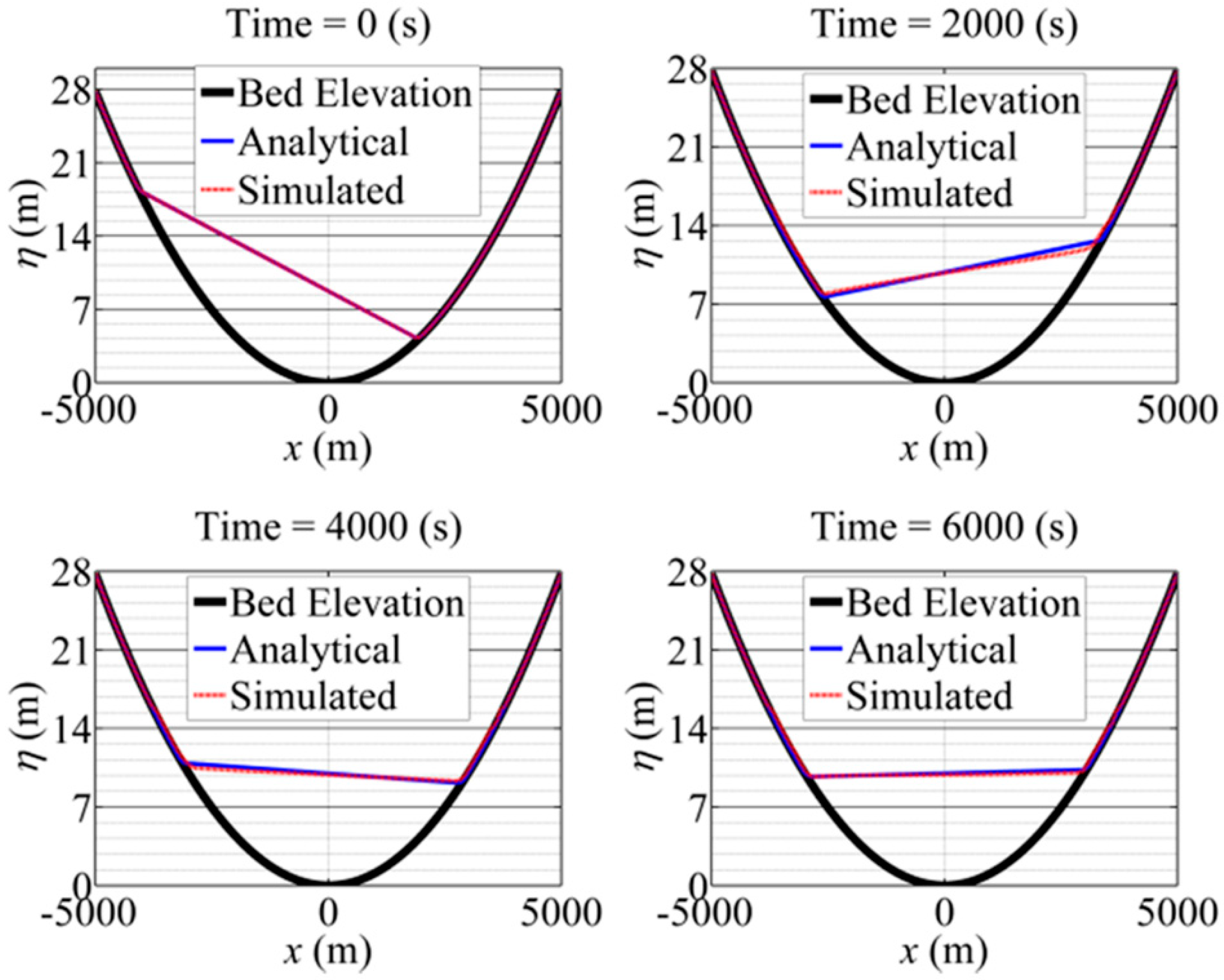
The Boussinesq model is first validated with analytical solutions for water sloshing in a frictional parabolic container to validate the model’s mass conservations. The oscillating water surface in the container is damped by the bed friction as a function of the flow depth and local velocity. The parabolic bed elevation and analytical water surface is the same as in Liang and Borthwick’s study [26]. The numerical domain is 10,000 m long and 1000 m wide. The spatial step is 20 m and the total simulation time was 6000 s. The simulated water surface compared with the analytical solution is shown in Figure 2. The initial water surface difference is more than 10 m between the left and right walls. This difference and oscillatory flow is damped gradually at 2000 s, 4000 s, and 6000 s. The strong agreement between simulated and analytical solutions verifies the capability of the model in dealing with complex topography and wet and dry boundaries. The conservation of water mass during the whole simulation is also confirmed.

3.2. Case II: Conservation of Solitary Wave Propagation

The stability and conservative properties of the Boussinesq wave model is tested by the simulation of solitary wave propagation in a flat, frictionless channel, as in Orszaghova et al. [32]. The channel length is 500 m and width is 80 m. The uniform grid resolution is 5 m. The solitary wave with an amplitude of 0.01 m is assumed at x = 100 m in the otherwise still water channel with a depth of 1 m. The total simulation time is 80 s. The simulation stopped before the wave could reach the downstream boundary, and there is no special treatment for the reflective boundary. Since the bed is frictionless, the initial solitary wave is expected to propagate downstream with the same profile. Simulated results in Figure 3 show that the wave form is preserved during its propagations at different times of 0, 20, 40, 60, and 80 s. This confirms the accuracy of the model.

3.3. Case III: Tsunami Wave in a Laboratory Flume

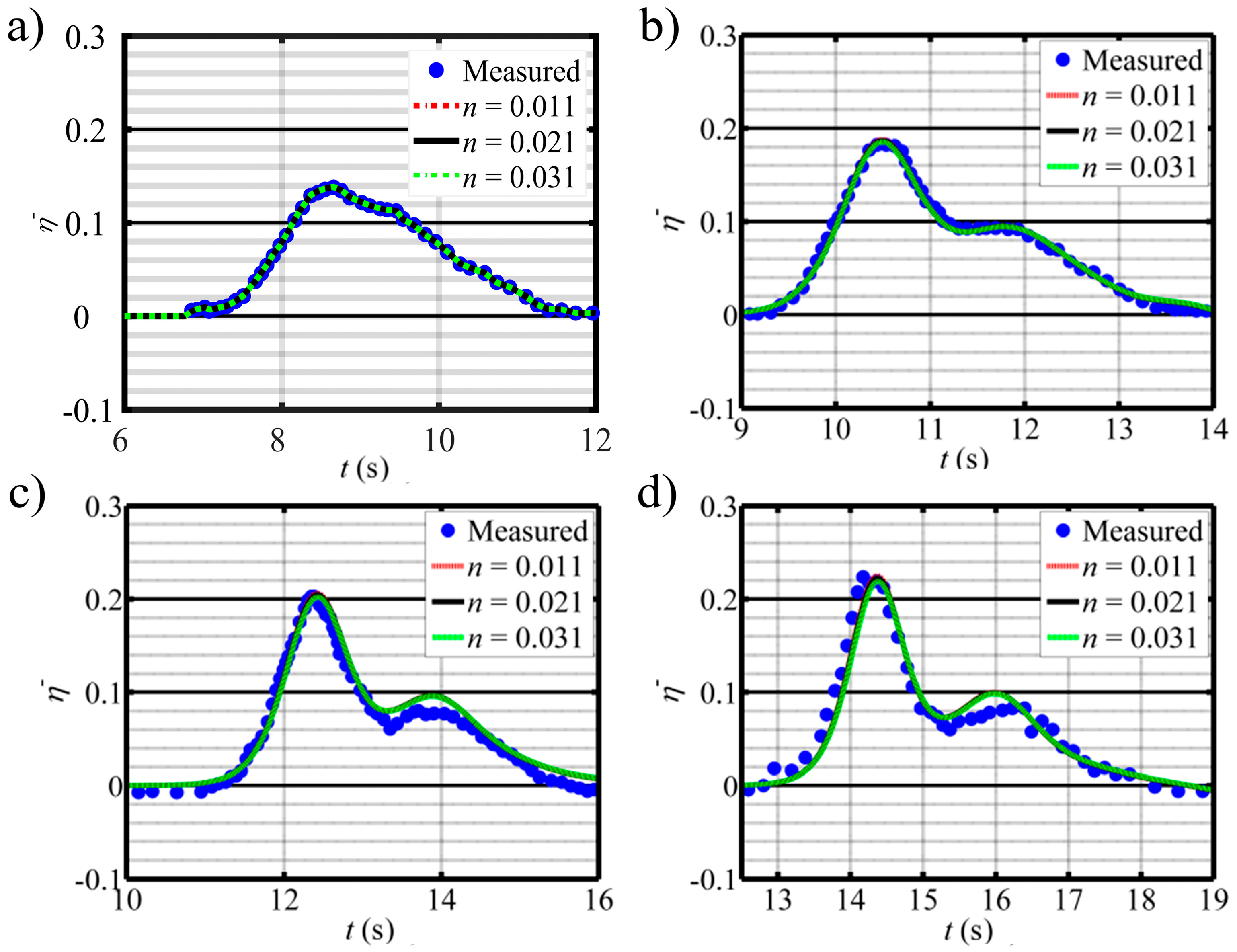
Yasuda [33] conducted a set of experiments on tsunami wave propagation in a laboratory flume. The channel was 34 m long and 5 m wide. The bed slope of the last 28 m was 1/250 and the first 6 m was flat, where a target wave height of 0.05 m and period of 5 s was generated by the wave paddle. The still water level was 0.4 m and the wave elevation was recorded at x = 10   m , 14 m, 18 m, and 22 m. Yasuda’s experimental run 9 is used to validate the model capability in simulating wave transformations during the propagation. Based on the experimental setup, the downstream boundary is a constant discharge of 0.0 with zero input velocities there. The measured elevation at 10 m is used as the upstream boundary condition and a reflective boundary condition is used at the downstream. The longitudinal grid resolution ranges from 0.02 to 0.1 m and the transverse grid resolution is 0.1 m. The total simulation time is 20 s. Figure 4 shows simulated wave forms under varying channel roughness in comparison with measured data at different gauging points, where the dimensionless wave height η ¯ is the wave height divided by the still water depth. Both the simulated and measured wave propagations show that the wave height increases as it climbs up to the shallower water channel. That is because of wave shoaling. The simulation reproduces the experimental wave propagation over a sloping channel. The single-peak wave splits into two peaks when it climbs up the sloping channel due to wave dispersion. The simulated results agree well with the measured tsunami wave at different times and different locations. It further validates the capability and accuracy of the Boussinesq wave model. That aside, sensitivity analysis is conducted with the model on the Manning’s roughness coefficient n ranging from 0.011, 0.021, to 0.03. The simulated results show that the model is not sensitive to the roughness coefficient in simulating tsunami wave propagations in the flume.

4. Model Applications

Due to the limited data on tsunami waves, the Boussinesq wave model has not been applied to natural tsunami wave studies. More field observations are needed for understanding tsunami wave propagations in the coastal region. With the preceding model validations, the two-dimensional Boussinesq wave model is further applied to investigate ice attenuations on tsunami wave propagations over a beach, ice deposition on the beach driven by the tsunami wave, and ice jamming and release caused by the tsunami wave in a coastal channel. They aim to illustrate the interactions between tsunami wave propagation and ice movement. In the future, flume experiments might be conducted to investigate the solitary wave propagations along a sloping beach with the influence of the ice. Such experiments will provide useful data for understanding the interaction between wave propagation and ice movement, and calibrating or validating numerical models.

4.1. Ice Effect on Tsunami Wave Propagations over a Beach

A 1500 m long beach with a constant slope of 0.002 is used to show the interaction between the tsunami wave and ice. A 2 m still water level is assumed to be the initial sea water level without wave. A surge increasing from 2 m to 2.7 m within 4 h and remaining at 2.7 m afterward is used as the upstream boundary at x = 1500 m. The flow velocities at upstream nodes are calculated from the flow equations. The bed roughness coefficient is 0.025. With the same flow boundary, four separated simulation runs are conducted to show the effect of ice concentration. Along with the incoming surge, surface ice with a thickness of 0.1 m and a concentration (N) of 0.0, 0.2, 0.4, and 0.6, respectively, is issued at the upstream boundary. The downstream boundary at x = 0   m is supposed to be the discharge, but these boundaries nodes are dry and zero velocities are assigned in the dry beach nodes. The downstream boundary is a dry beach and is reflective. No wave-breaking is considered. The spatial grid resolution is 5 m, and the width of the domain is 100 m. The ice roughness increases linearly with its thickness from 0.02 to 0.06. The uniform grid resolution is 1 m and the total simulation time is 5 h. The simulated final stages are shown in Figure 5, which illustrates wave propagation along the beach for various incoming ice concentrations. When the ice concentration increases, the wave moves slower and its run-up distance is shorter. The ice attenuates the wave, as wave energy dissipates faster with the increasing ice concentration. In addition, ice climbs higher on the beach when the ice concentration is lower. That means the wave energy is stronger in pushing ice up on the beach, in terms of lower ice concentration. The existence of a large amount of ice causes more energy loss, due to interactions between waves and ice.

4.2. Ice Deposition on the Beach

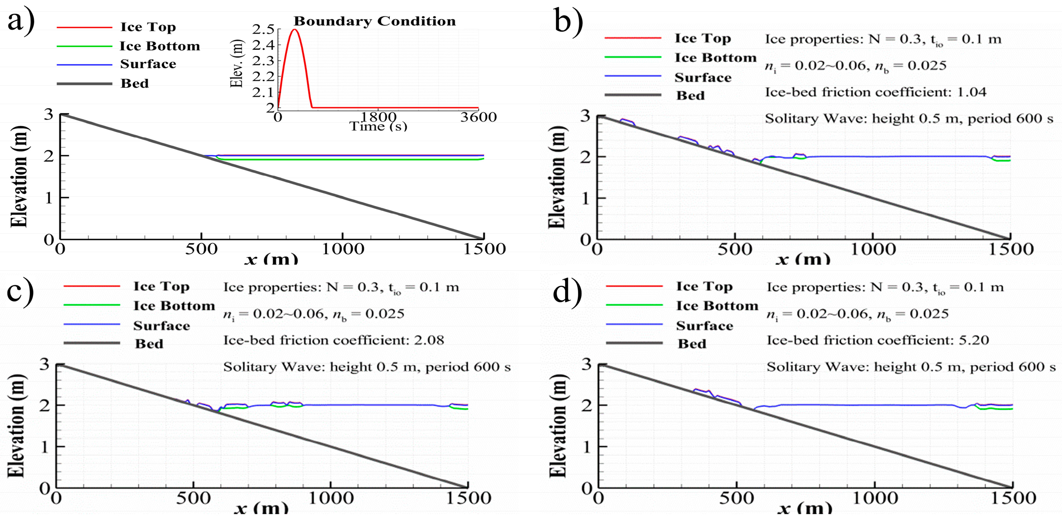
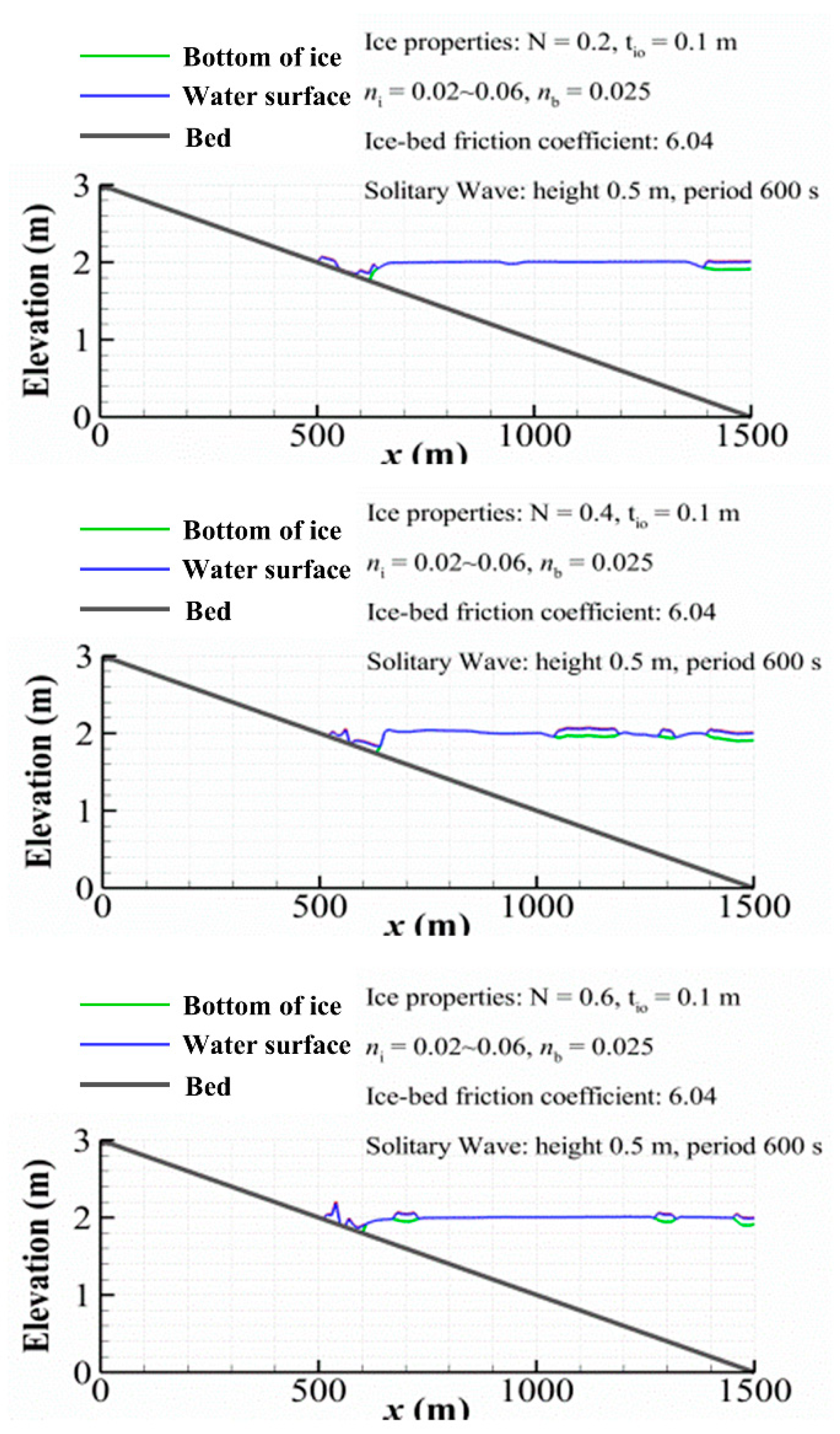
Ice deposition on the beach is examined in this case. The upstream boundary conditions are provided at x = 1500   m by a solitary wave increasing from 2.0 m to 2.5 m with a period of 600 s, as shown in the insert of Figure 6. Since the downstream boundary is the dry beach, the wave is reflected back there without considering wave breaking processes, the same as that in Section 4.1. The single solitary wave is used to represent the tsunami wave. Initially, the water is at rest and the velocity is zero in the whole domain. The water surface is covered by ice with an initial concentration of 0.3 and thickness of 0.1 m. Three simulation runs are conducted for ice deposition on the beach affected by different ice-bed frictions, respectively. Three ice-bed friction coefficients (defined as f i b = tan ϕ i b and ϕ i b is the ice-bed friction angle), 1.04, 2.08, and 5.20, are examined and their corresponding ice-bed friction angles are 46°, 64°, 79°. The friction force between ice and the beach increases with the growing ice-bed friction coefficient. When the ice-bed friction is larger, ice deposition on the beach is larger but the ice run-up is smaller. For a given ice-bed friction coefficient of 6.04 or ϕ i b = 81°, the water surface is initially covered by ice parcels with three ice concentrations, 0.2, 0.4, and 0.6. Using the same solitary wave, the final ice depositions on the beach are shown in Figure 7 for simulated results at 3600 s. The ice top indicates the top elevation of the floating ice, and its bottom location is represented by ice bottom with “Surface”, indicating water surface level in all following figures. When ice concentration increases, the ice deposition area decreases, but the maximum accumulated ice thickness increases. The tsunami wave driven ice deposition is sensitive to the ice-bed friction coefficient and the initial ice concentration.

4.3. Ice jamming in River Channel with Incoming Tsunami Wave

The ice jam dynamics in a rectangular channel of 15 km long and 600 m wide with the intrusion of a tsunami wave is simulated by the model. The bed slope of the first 5 km is 0.003, and the remaining 10 km is 0.0003. The bed roughness coefficient is 0.03. The grid resolutions are 30 m in the longitudinal direction and 40 m in the transverse direction. The upstream boundary conditions are a constant water discharge of 2000 m3/s with surface ice thickness of 0.4 m and concentration of 0.6. The velocities at upstream cross-section nodes are calculated based on the inflow discharge and simulated water depth. The downstream boundary condition is a solitary wave with 4 m height and a 900 s period. No special treatment is used for the reflective boundary as the wave dies out before it reflects back. The initial flow condition and longitudinal ice profiles are shown in Figure 8. The total simulation time is 3600 s.
The ice thickness distribution, velocity profiles, longitudinal water surface, and ice profiles are shown at simulation times of 7.5, 12, 13, 14.3, 18, and 22.5 min in Figure 9. The top plots show the ice thickness accumulations in color from the ice jam and water velocity vectors in the two-dimensional domain. The longitudinal water level, bed elevation, and ice thickness profiles are shown in the lower plots with enlarged plots for the area in the green box. The downstream boundary is shown in the middle right plot with a red line for the intruding wave and green points for wave height at current simulating time. When the intruding wave propagates and meeting flow and ice blocks from upstream, ice thickening appears at the wave front and gradually grows into an ice jam at 12 min. The maximum thickness of the ice jam exceeds 6.5 m and the jam bottom reaches the channel bed. After that, ice jams are partially released and then reformed upstream, due to accumulations of ice with decreasing wave height from 13 to 22.5 min. The ice jam moves further upstream as the wave propagates upstream. During the propagation, the wave attenuates and the size of the ice jam decreases. Finally, the wave dies out and the ice jam is released.

5. Conclusions

A Boussinesq-type wave model coupled with ice dynamics was developed for studying ice effects on tsunami wave propagation on beaches and in channels. The model was first validated with analytical solutions and flume data. It was then used to study the interaction between tsunami waves and surface ice. The study showed that floating ice will slow down the wave propagation and shorten the run-up distance. Ice deposition on the beach is dominated by the ice-bed friction and the availability of ice. Depositions are more likely to occur with higher ice-bed friction. Ice deposition area decreases with the increase in ice concentration, but its maximum thickness increases with ice concentration. When a tsunami wave propagates into a channel with floating ice, an ice jam may develop. A preliminary study was conducted on simulating interactions between surface ice movement and tsunami wave propagations. More quantitative comparisons with field observations and experimental data are needed in the future.

Author Contributions

H.S. conceived and designed the research with J.P.; J.P. developed the code and performed the model simulations; J.P. and H.S. wrote the manuscript.

Funding

The first author appreciates the financial support of National Key Research and Development Program of China (No. 2017YFC0405502) and Natural Science Foundation of Zhejiang Province (No. R16E090002).

Acknowledgments

The work was initiated during the writers visit at NEWRI, Nanyang Technological University. The first author appreciated the financial support from Zhejiang province.

Conflicts of Interest

The authors declare no conflict of interest.

References

  1. Peregrine, D. Long waves on a beach. J. Fluid Mech. 1967, 27, 815–827. [Google Scholar] [CrossRef]
  2. Madsen, P.A.; Murray, R.; Sørensen, O.R. A new form of the Boussinesq equations with improved linear dispersion characteristics. Coast. Eng. 1991, 15, 371–388. [Google Scholar] [CrossRef]
  3. Nwogu, O. Alternative form of Boussinesq equations for nearshore wave propagation. J. Waterwy. Port Coast. Ocean. Eng. 1993, 119, 618–638. [Google Scholar] [CrossRef]
  4. Wei, G.; Kirby, J.T. Time-dependent numerical code for extended Boussinesq equations. J. Waterway. Port Coast. Ocean. Eng. 1995, 121, 251–261. [Google Scholar] [CrossRef]
  5. Madsen, P.A.; Schäffer, H.A. Higher–order Boussinesq–type equations for surface gravity waves: Derivation and analysis. Philos. Trans. R. Soc. Lond. Ser. A Math. Phys. Eng. Sci. 1998, 356, 3123–3181. [Google Scholar] [CrossRef]
  6. Agnon, Y.; Madsen, P.A.; Schäffer, H. A new approach to high-order Boussinesq models. J. Fluid Mech. 1999, 399, 319–333. [Google Scholar] [CrossRef]
  7. Zou, Z.L. Higher order Boussinesq equations. Ocean. Eng. 1999, 26, 767–792. [Google Scholar] [CrossRef]
  8. Gobbi, M.F.; Kirby, J.T.; Wei, G.E. A fully nonlinear Boussinesq model for surface waves. Part 2. Extension to O(kh)4. J. Fluid Mech. 2000, 405, 181–210. [Google Scholar] [CrossRef]
  9. Madsen, P.A.; Fuhrman, D.R. High-order Boussinesq-type modelling of nonlinear wave phenomena in deep and shallow water. In Advances in Numerical Simulation of Nonlinear Water Waves; World Scientific: Singapore, 2010; Volume 11, pp. 245–285. [Google Scholar]
  10. Shi, F.; Kirby, J.T.; Harris, J.C.; Geiman, J.D.; Grilli, S.T. A high-order adaptive time-stepping TVD solver for Boussinesq modeling of breaking waves and coastal inundation. Ocean. Model. 2012, 43, 36–51. [Google Scholar] [CrossRef]
  11. Debsarma, S.; Das, K.P.; Kirby, J.T. Fully nonlinear higher-order model equations for long internal waves in a two-fluid system. J. Fluid Mech. 2010, 654, 281–303. [Google Scholar] [CrossRef] [Green Version]
  12. Fang, K.; Zou, Z.; Dong, P.; Liu, Z.; Gui, Q.; Yin, J. An efficient shock capturing algorithm to the extended Boussinesq wave equations. Appl. Ocean. Res. 2013, 43, 11–20. [Google Scholar] [CrossRef]
  13. Yao, Y.; Huang, Z.; Monismith, S.G.; Lo, E.Y.M. 1DH Boussinesq modeling of wave transformation over fringing reefs. Ocean. Eng. 2012, 47, 30–42. [Google Scholar] [CrossRef]
  14. Gaeta, M.; Bonaldo, D.; Samaras, A.; Carniel, S.; Archetti, R. Coupled wave-2D hydrodynamics modeling at the Reno River Mouth (Italy) under climate change scenarios. Water 2018, 10, 1380. [Google Scholar] [CrossRef]
  15. Petti, M.; Bosa, S.; Pascolo, S. Lagoon sediment dynamics: A coupled model to study a medium-term silting of tidal channels. Water 2018, 10, 569. [Google Scholar] [CrossRef]
  16. Li, Y.; Song, Z.; Peng, G.; Fang, X.; Li, R.; Chen, P.; Hong, H. Modeling hydro-dynamics in a Harbor Area in the Daishan Island, China. Water 2019, 11, 192. [Google Scholar] [CrossRef]
  17. Brunt, K.M.; Okal, E.A.; MacAyeal, D.R. Antarctic ice-shelf calving triggered by the Honshu (Japan) earthquake and tsunami, March 2011. J. Glaciol. 2011, 57, 785–788. [Google Scholar] [CrossRef] [Green Version]
  18. Kaistrenko, V.; Razjigaeva, N.; Kharlamov, A.; Shishkin, A. Manifestation of the 2011 Great Tohoku Tsunami on the coast of the Kuril Islands: A tsunami with Ice. Pure Appl. Geophys. 2013, 170, 1103–1114. [Google Scholar] [CrossRef]
  19. Shen, H.T.; Wang, D.S.; Lal, A.W. Numerical simulation of river ice processes. J. Cold Reg. Eng. 1995, 9, 107–118. [Google Scholar] [CrossRef]
  20. Shen, H.T.; Su, J.; Liu, L. SPH simulation of river ice dynamics. J. Comput. Phys. 2000, 165, 752–770. [Google Scholar] [CrossRef]
  21. Knack, I.M.; Shen, H.T. A numerical model study on Saint John River ice breakup. Can. J. Civ. Eng. 2016, 45, 817–826. [Google Scholar] [CrossRef]
  22. Shen, H.T.; Liu, L. Shokotsu River ice jam formation. Cold Reg. Sci. Technol. 2003, 37, 35–49. [Google Scholar] [CrossRef]
  23. Kolerski, T.; Shen, H.T. Possible effects of the 1984 St. Clair River ice jam on bed changes. Can. J. Civ. Eng. 2015, 42, 696–703. [Google Scholar] [CrossRef]
  24. Madsen, P.A.; Sørensen, O.R. A new form of the Boussinesq equations with improved linear dispersion characteristics. Part 2. A slowly-varying bathymetry. Coast. Eng. 1992, 18, 183–204. [Google Scholar] [CrossRef]
  25. Tonelli, M.; Petti, M. Shock-capturing Boussinesq model for irregular wave propagation. Coast. Eng. 2012, 61, 8–19. [Google Scholar] [CrossRef]
  26. Liang, Q.; Borthwick, A.G.L. Adaptive quadtree simulation of shallow flows with wet-dry fronts over complex topography. Comput. Fluids 2009, 38, 221–234. [Google Scholar] [CrossRef]
  27. Tonelli, M.; Petti, M. Numerical simulation of wave overtopping at coastal dikes and low-crested structures by means of a shock-capturing Boussinesq model. Coast. Eng. 2013, 79, 75–88. [Google Scholar] [CrossRef]
  28. Toro, E.F. Riemann Solvers and Numerical Methods for Fluid Dynamics: A Practical Introduction; Springer: Berlin/Heidelberg, Germany, 2009; Volume 16, p. 724. [Google Scholar]
  29. Erduran, K.; Ilic, S.; Kutija, V. Hybrid finite-volume finite-difference scheme for the solution of Boussinesq equations. Int. J. Numer. Methods Fluids 2005, 49, 1213–1232. [Google Scholar] [CrossRef]
  30. Shen, H.T. Mathematical modeling of river ice processes. Cold Reg. Sci. Technol. 2010, 62, 3–13. [Google Scholar] [CrossRef]
  31. Ji, S.-Y.; Shen, H.T.; Wang, Z.-L.; Shen, H.H.; Yue, Q. A viscoelastic-plastic constitutive model with Mohr-Coulomb yielding criterion for sea ice dynamics. Acta Oceanol. Sin. Engl. Ed. 2005, 24, 54. [Google Scholar]
  32. Orszaghova, J.; Borthwick, A.G.; Taylor, P.H. From the paddle to the beach—A Boussinesq shallow water numerical wave tank based on Madsen and Sørensen’s equations. J. Comput. Phys. 2012, 231, 328–344. [Google Scholar] [CrossRef]
  33. Yasuda, H. One-dimensional study on propagation of tsunami wave in river channels. J. Hydraul. Eng. 2010, 136, 93–105. [Google Scholar] [CrossRef]
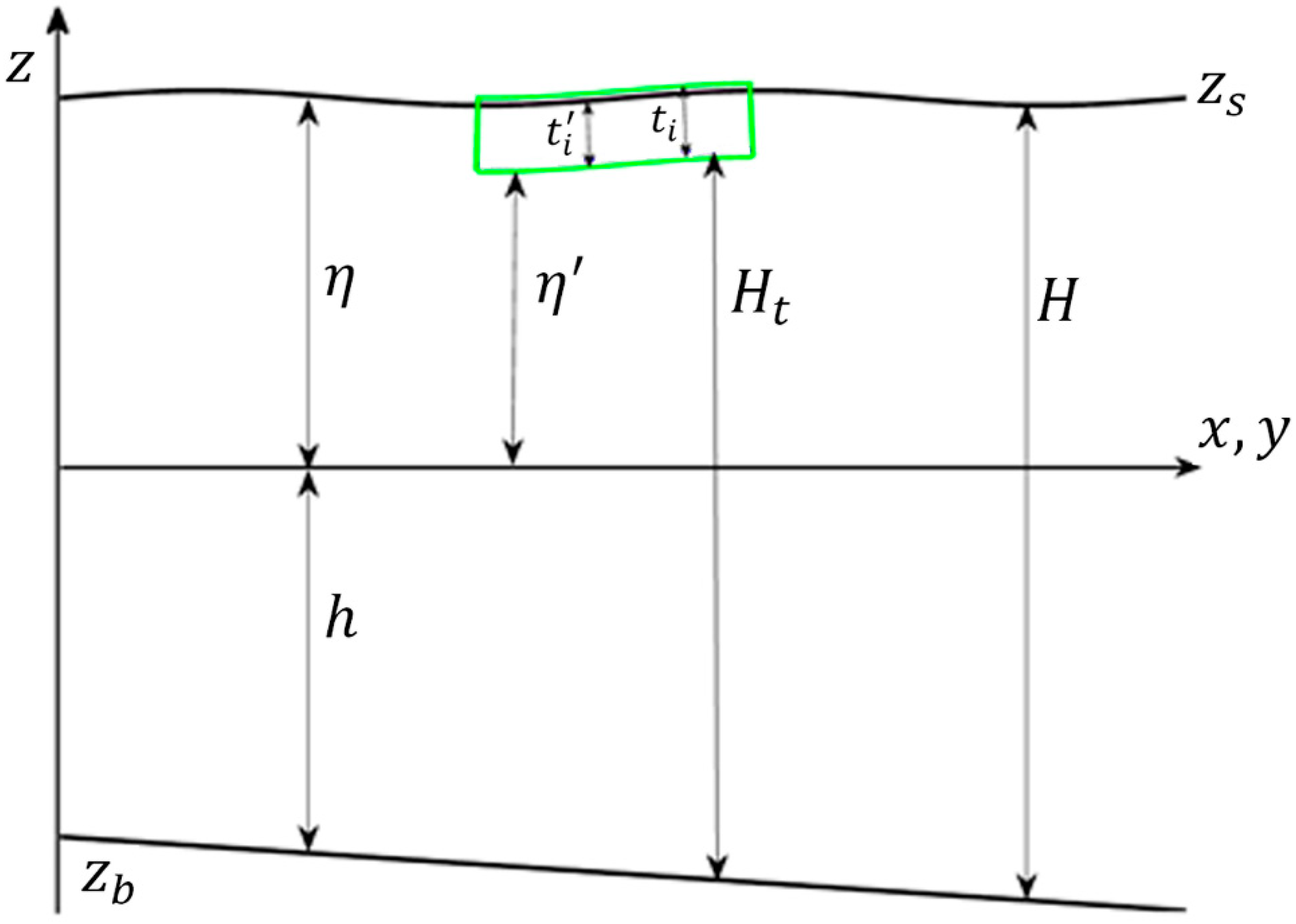
Figure 1. Sketch of the hydrodynamic domain with the floating ice indicated by the color box.
Water 11 01290 g001
Figure 2. Simulated water surface elevations over a parabolic topography at time = 0 s, 2000 s, 4000 s, and 6000 s.
Water 11 01290 g002
Figure 3. Simulated solitary wave in a frictionless channel.
Water 11 01290 g003
Figure 4. Comparison between measured and simulated waveforms with different Manning roughness at x = (a) 10 m, (b) 14 m, (c) 18 m, and (d) 22 m.
Water 11 01290 g004
Figure 5. Effect of ice concentrations on the surge run-up in the beach at times: 0 s, 8640 s, and 17,280 s.
Water 11 01290 g005
Figure 6. Simulated ice depositions on the beach under a tsunami wave with different ice-bed friction coefficients: (a) Initial water surface, ice bottom and top elevations, and the tsunami wave boundary conditions; simulated water surface and ice depositions on the beach with the ice-bed friction coefficient of (b) 1.04, (c) 2.08, and (d) 5.20. The red line in the subfigure is the upstream water level boundary.
Water 11 01290 g006
Figure 7. Effect of ice concentration on ice deposition on the beach.
Water 11 01290 g007
Figure 8. Initial flow and ice conditions in a slope-varying channel.
Water 11 01290 g008
Figure 9. Scenarios of ice jam profiles produced by intrusion of tsunami wave. The colored contour plots indicate ice thickness distribution with two-dimensional velocity vectors.
Water 11 01290 g009