Supplied Sediment Tracking for Bridge Collapse with Large-Scale Channel Migration


Abstract
:1. Introduction
2. Study Site
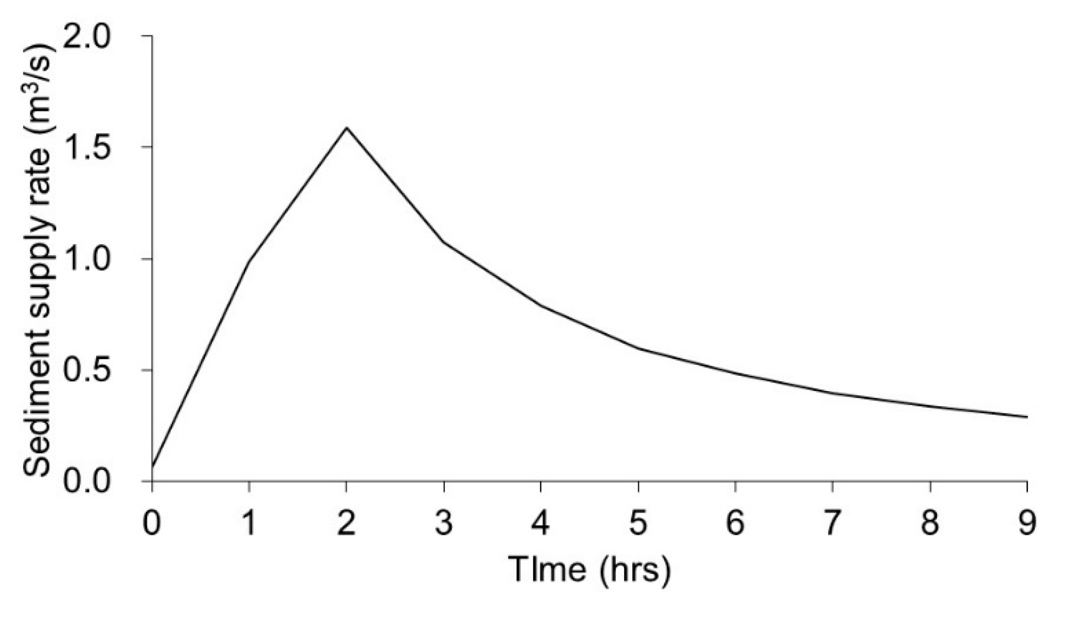
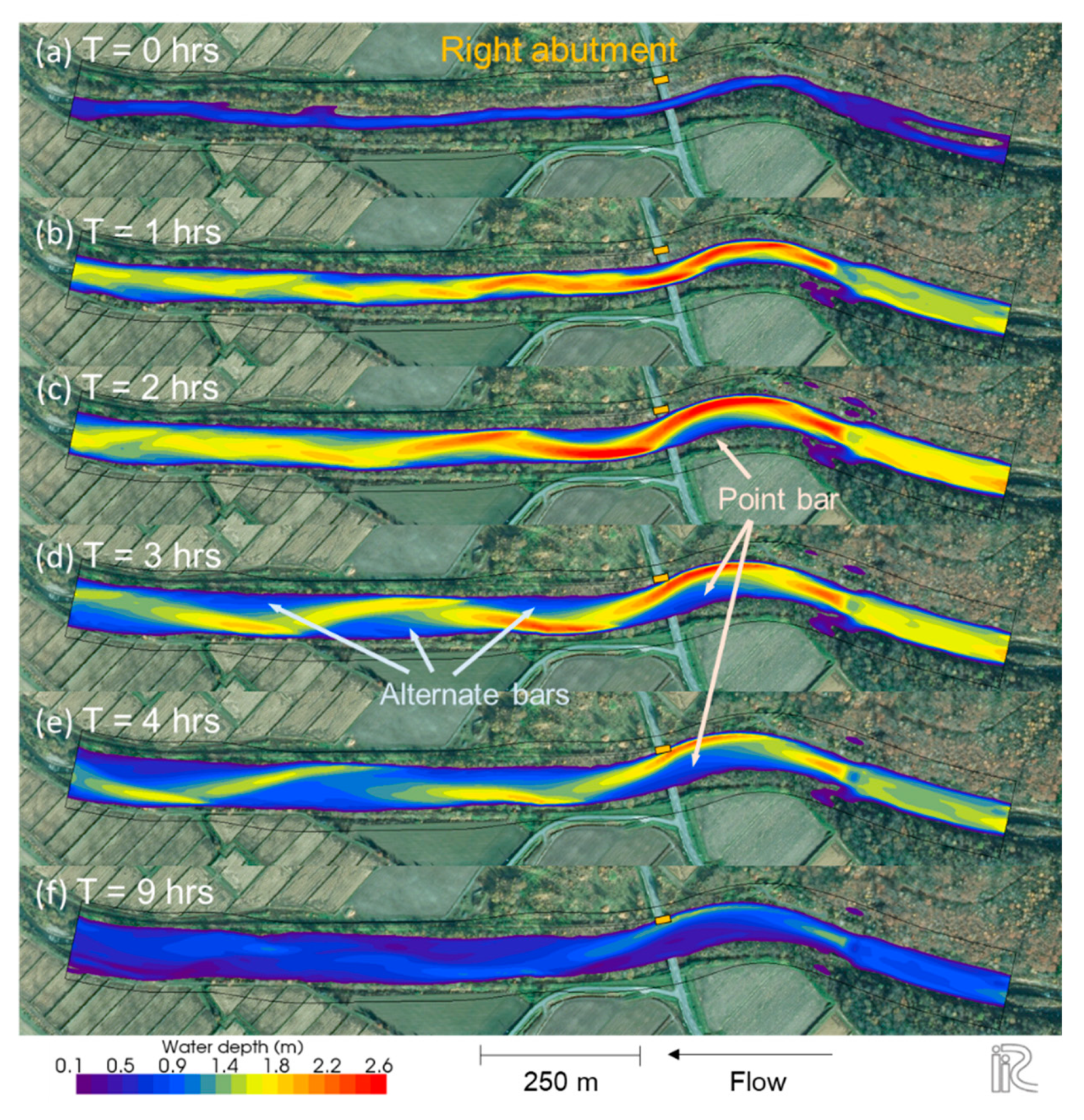
3. Methods
4. Results
5. Discussion
6. Conclusions
Author Contributions
Funding
Acknowledgments
Conflicts of Interest
References
- Pizarro, A.; Manfreda, S.; Tubaldi, E. The Science behind Scour at Bridge Foundations: A Review. Water 2020, 12, 374. [Google Scholar] [CrossRef] [Green Version]
- Johnson, P.A.; Whittington, R.M. Vulnerability-Based Risk Assessment for Stream Instability at Bridges. J. Hydraul. Eng. 2011, 137, 1248–1256. [Google Scholar] [CrossRef]
- Johnson, P.A. Preliminary Assessment and Rating of Stream Channel Stability near Bridges. J. Hydraul. Eng. 2005, 131, 845–852. [Google Scholar] [CrossRef] [Green Version]
- Aoki, T.; Inoue, T. Research on measures to stabilize abutment backfills against river channel migration. Adv. River Eng. JSCE 2020, 26. in press. (In Japanese) [Google Scholar]
- Wohl, E. Legacy effects on sediments in river corridors. Earth-Sci. Rev. 2015, 147, 30–53. [Google Scholar] [CrossRef]
- Papanicolaou, A.; Wilson, C.; Dermisis, D.; Elhakeem, M. The effects of headcut and knickpoint propagation on bridges in Iowa. Final Rep. Submitt. Iowa Dep. Transp. Highw. Div. Iowa Highw. Res. Board 2008, 1–57. Available online: http://publications.iowa.gov/20055/ (accessed on 29 May 2020).
- Parker, G.; Izumi, N. Purely erosional cyclic and solitary stepscreated by flow over a cohesive bed. J. Fluid Mech. 2000, 419, 203–238. [Google Scholar] [CrossRef]
- Sumner, T.; Inoue, T.; Shimizu, Y. The influence of bed slope change on erosional morphology. J. JSCE 2019, 7, 15–21. [Google Scholar] [CrossRef] [Green Version]
- Nelson, P.A.; Venditti, J.G.; Dietrich, W.E.; Kirchner, J.W.; Ikeda, H.; Iseya, F.; Sklar, L.S. Response of bed surface patchiness to reductions in sediment supply. J. Geophys. Res. 2009, 114, F02005. [Google Scholar] [CrossRef] [Green Version]
- Venditti, J.G.; Nelson, P.A.; Minear, J.T.; Wooster, J.; Dietrich, W.E. Alternate bar response to sediment supply termination. J. Geophys. Res. 2012, 117, F02039. [Google Scholar] [CrossRef]
- Inoue, T.; Nelson, J.M. An experimental study of longitudinal incisional grooves in a mixed bedrock–alluvial channel. Water Resour. Res. 2020, 56, e2019WR025410. [Google Scholar] [CrossRef]
- Gilbert, G.K. Report on the Geology of the Henry Mountains: Geographical and Geological Survey of the Rocky Mountain Region; U.S. Government Publishing Office: Washington, DC, USA, 1877; p. 160. [CrossRef] [Green Version]
- Inoue, T.; Parker, G.; Stark, C.P. Morphodynamics of a bedrock-alluvial meander bend that incises as it migrates outward: Approximate solution of permanent form. Earth Surf. Process. Landf. 2017, 42, 1342–1354. [Google Scholar] [CrossRef]
- Mishra, J.; Inoue, T.; Shimizu, Y.; Sumner, T.; Nelson, J.M. Consequences of abrading bed load on vertical and lateral bedrock erosion in a curved experimental channel. J. Geophys. Res. Earth Surf. 2018, 123, 3147–3161. [Google Scholar] [CrossRef]
- Ashworth, P.J.; Best, J.L.; Jones, M. Relationship between sediment supply and avulsion frequency in braided rivers. Geology 2004, 32, 21–24. [Google Scholar] [CrossRef]
- Davies, T.R.H.; Korup, O. Persistent alluvial fanhead trenching resulting fromlarge, infrequent sediment inputs. Earth Surf. Process. Landf. 2007, 32, 725–742. [Google Scholar] [CrossRef]
- Croissant, T.; Lague, D.; Davy, P.; Davies, T.; Steer, P. A precipiton-based approach to model hydro-sedimentary hazards induced by large sediment supplies in alluvial fans. Earth Surf. Process. Landf. 2017, 42, 2054–2067. [Google Scholar] [CrossRef]
- Church, M. Bed material transport and the morphology of alluvial river channels. Annu. Rev. Earth Planet. Sci. 2006, 4, 325–354. [Google Scholar] [CrossRef]
- Blondeaux, P.; Seminara, G. A unified bar-bend theory of river meanders. J. Fluid Mech. 1985, 157, 449–470. [Google Scholar] [CrossRef]
- Ikeda, S.; Parker, G.; Sawai, K. Bend theory of river meanders. Part 1. Linear development. J. Fluid Mech. 1981, 112, 363–377. [Google Scholar] [CrossRef]
- Johannesson, H.; Parker, G. Secondary flow in mildly sinuous channel. J. Fluid Mech. 1989, 115, 289–308. [Google Scholar] [CrossRef]
- Braudricka, C.A.; Dietrich, W.E.; Leverich, G.T.; Sklar, L.S. Experimental evidence for the conditions necessary to sustain meandering in coarse-bedded rivers. Proc. Natl. Acad. Sci. USA 2009, 106, 16936–16941. [Google Scholar] [CrossRef] [Green Version]
- Darby, S.E.; Alabyan, A.M.; Van de Wiel, M.J. Numerical simulation of bank erosion and channel migration in meandering rivers. Water Resour. Res. 2002, 38, 1163. [Google Scholar] [CrossRef]
- Duan, J.G.; Julien, P.Y. Numerical simulation of the inception of channel meandering. Earth Surf. Process. Landf. 2005, 30, 1093–1110. [Google Scholar] [CrossRef]
- Olsen, N.R.B. Three-dimensional CFD modelling of selfforming meandering channel. J. Hydraul. Eng. 2003, 129, 366–372. [Google Scholar] [CrossRef]
- Jang, C.L.; Shimizu, Y. Numerical simulation of relatively wide, shallow channels with erodible banks. J. Hydraul. Eng. 2005, 131, 565–575. [Google Scholar] [CrossRef] [Green Version]
- Asahi, K.; Shimizu, Y.; Nelson, J.; Parker, G. Numerical simulation of river meandering with self-evolving banks. J. Geophys. Res. Earth Surf. 2013, 118, 2208–2229. [Google Scholar] [CrossRef]
- Nicholas, A.P. Modelling the continuum of river channel patterns. Earth Surf. Process. Landf. 2013, 38, 1187–1196. [Google Scholar] [CrossRef]
- Eke, E.; Parker, G.; Shimizu, Y. Numerical modeling of erosional and depositional bank processes in migrating river bends with self-formed width: Morphodynamics of bar push and bank pull. J. Geophys. Res. Earth Surf. 2014, 119, 1455–1483. [Google Scholar] [CrossRef]
- Nagata, T.; Watanabe, Y.; Shimizu, Y.; Inoue, T.; Funaki, J. Study on dynamics of river channel and vegetation in gravel bed river. J. JSCE. Ser. B1 2016, 72, 1081–1086. (In Japanese) [Google Scholar] [CrossRef] [Green Version]
- Oorschot, M.; Kleinhans, M.; Geerling, G.; Middelkoop, H. Distinct patterns of interaction between vegetation and morphodynamics. Earth Surf. Process. Landf. 2016, 41, 791–808. [Google Scholar] [CrossRef]
- Kim, Y.G.; Kimura, I.; Shimizu, Y. Experiment and Computation of Morphological Response to a Vegetation Patch in Open-Channel Flows with Erodible Banks. Water 2019, 11, 2255. [Google Scholar] [CrossRef] [Green Version]
- Lai, Y.G.; Thomas, R.E.; Ozeren, Y.; Simon, A.; Greimann, B.P.; Wu, K. Modeling of multilayer cohesive bank erosion with a coupled bank stability and mobile-bed model. Geomorphology 2015, 243, 116–129. [Google Scholar] [CrossRef] [Green Version]
- Arnez Ferrel, K.R.; Patsinghasanee, S.; Kimura, I.; Shimizu, Y. Coupled Model of Bank Erosion and Meander Evolution for Cohesive Riverbanks. Geosciences 2018, 8, 359. [Google Scholar] [CrossRef] [Green Version]
- Sayre, W.; Hubbell, D. Transport and dispersion of labeled bed material, North Loup River, Nebraska, U.S. Geol. Surv. Prof. Pap. 1965, 433-C, 1–48. [Google Scholar]
- Hoey, T.B. Sediment dispersion and duration of storage in a model braided river. J. Hydrol. N. Z. 1996, 35, 213–237. [Google Scholar]
- Olinde, L.; Johnson, J.P.L. Using RFID and accelerometer-embedded tracers to measure probabilities of bed load transport, step lengths, and rest times in a mountain stream. Water Resour. Res. 2015, 51, 7572–7589. [Google Scholar] [CrossRef] [Green Version]
- Iwasaki, T.; Nelson, J.; Shimizu, Y.; Parker, G. Numerical simulation of large-scale bed load particle tracer advection-dispersion in rivers with free bars. J. Geophys. Res. Earth Surf. 2017, 122, 847–874. [Google Scholar] [CrossRef]
- Hirano, M. River bed degradation with armoring. Proc. Jpn. Soc. Civ. Eng. 1971, 195, 55–65. (In Japanese) [Google Scholar] [CrossRef] [Green Version]
- Ashida, K.; Egashira, S.; Liu, B. Numerical Method on Sediment Sorting and Bed Variation in Meander Channels. Proc. Hydraul. Eng. 1991, 35, 383–390. [Google Scholar] [CrossRef]
- Water information system. Ministry of Land, Infrastructure, Transport and Tourism, Japan. Available online: http://www1.river.go.jp/ (accessed on 21 June 2020). (In Japanese).
- Shimizu, Y.; Takebayashi, H.; Inoue, T.; Hamaki, M.; Iwasaki, T.; Nabi, M. Nays2DH solver manual. 2014. Available online: http://i-ric.org/en (accessed on 29 May 2020).
- Meyer-Peter, E.; Müller, R. Formulas for bed load transport. In Proceedings of the 2nd Meeting of the International Association for Hydraulic Structures Research, Delft, The Netherlands, 7 June 1948; pp. 39–64. [Google Scholar]
- Hasegawa, K. Universal bank erosion coefficient for meandering rivers. J. Hydraul. Eng. 1989, 115, 744–765. [Google Scholar] [CrossRef]
- Buffington, J.M.; Montgomery, D.R. A systematic analysis of 690 eight decades of incipient motion studies, with special reference to 691 gravel-bedded rivers. Water Resour. Res. 1997, 33, 1993–2029. [Google Scholar] [CrossRef] [Green Version]
- Berenbrock, C.; Tranmer, A.W. Simulation of flow, sediment transport, and sediment mobility of the Lower Coeur d’Alene River, Idaho. In U.S. Geological Survey Scientific Investigations Report 2008-5093; US Geological Survey: Reston, VA, USA, 2008; pp. 1–164. [Google Scholar]
- Engelund, F. Flow and bed topography in channel bends. J. Hydraul. Div. Asce 1974, 100. [Google Scholar]
- Crosato, A.; Mosselman, E. An Integrated Review of River Bars for Engineering, Management and Transdisciplinary Research. Water 2020, 12, 596. [Google Scholar] [CrossRef] [Green Version]
- Guzzetti, F.; Peruccacci, S.; Rossi, M.; Stark, C.P. The rainfall intensity-duration control of shallow landslides and debris flows: An update. Landslides 2008, 5, 3–17. [Google Scholar] [CrossRef]
- Lisle, T.E. The evolution of sediment waves influenced by varying transportcapacity in heterogeneous rivers. Gravel-Bed Rivers VI Process Underst. River Restor. 2008, 11, 443–469. [Google Scholar] [CrossRef]
- James, L.A. Secular sediment waves, channel bed waves, and legacy sediment. Geogr. Compass 2010, 4, 576–598. [Google Scholar] [CrossRef]
- Gran, K.B.; Czuba, J.A. Sediment pulse evolution and the role of network structure. Geomorphology 2017, 277, 17–30. [Google Scholar] [CrossRef]
- Bryant, M.; Falk, P.; Paola, C. Experimental study of avulsion frequency and rate of deposition. Geology 1995, 23, 365–368. [Google Scholar] [CrossRef]


© 2020 by the authors. Licensee MDPI, Basel, Switzerland. This article is an open access article distributed under the terms and conditions of the Creative Commons Attribution (CC BY) license (http://creativecommons.org/licenses/by/4.0/).
Share and Cite
Inoue, T.; Mishra, J.; Kato, K.; Sumner, T.; Shimizu, Y. Supplied Sediment Tracking for Bridge Collapse with Large-Scale Channel Migration. Water 2020, 12, 1881. https://doi.org/10.3390/w12071881
Inoue T, Mishra J, Kato K, Sumner T, Shimizu Y. Supplied Sediment Tracking for Bridge Collapse with Large-Scale Channel Migration. Water. 2020; 12(7):1881. https://doi.org/10.3390/w12071881
Chicago/Turabian StyleInoue, Takuya, Jagriti Mishra, Kazuo Kato, Tamaki Sumner, and Yasuyuki Shimizu. 2020. "Supplied Sediment Tracking for Bridge Collapse with Large-Scale Channel Migration" Water 12, no. 7: 1881. https://doi.org/10.3390/w12071881