Article

Exergy Optimization of a Solar Collector in Flat Plate Shape Equipped with Elliptical Pipes Filled with Turbulent Nanofluid Flow: A Study for Thermal Management

by
Sara Rostami
1,2,
Mohammad Sepehrirad
3,
Amin Dezfulizadeh
3,
Ahmed Kadhim Hussein
4,
Aysan Shahsavar Goldanlou
5,6,* and
Mostafa Safdari Shadloo
7
1
Laboratory of Magnetism and Magnetic Materials, Advanced Institute of Materials Science, Ton Duc Thang University, Ho Chi Minh City, Vietnam
2
Faculty of Applied Sciences, Ton Duc Thang University, Ho Chi Minh City, Vietnam
3
Department of Mechanical Engineering, Arak Branch, Islamic Azad University, Arak P.O. BOX 38135/567, Iran
4
College of Engineering—Mechanical Engineering Department, University of Babylon, Babylon City, Hilla 51002, Iraq
5
Institute of Research and Development, Duy Tan University, Da Nang 550000, Vietnam
6
Faculty of Electrical—Electronic Engineering, Duy Tan University, Da Nang 550000, Vietnam
7
CORIA-UMR 6614, CNRS-University, INSA of Rouen and Normandie University, 76000 Rouen, France
*
Author to whom correspondence should be addressed.
Water 2020, 12(8), 2294; https://doi.org/10.3390/w12082294
Submission received: 10 July 2020 / Revised: 4 August 2020 / Accepted: 7 August 2020 / Published: 14 August 2020
(This article belongs to the Special Issue Pipeline Fluid Mechanics 2020)

Abstract

:
In this paper, forced convection of a multiwalled carbon nanotube (MWCNT)–water nanofluid (NF) in a new flat plate solar collector (FPSC) equipped with elliptical pipes instead of circular ones is investigated. The three-dimensional conservation equations were solved in the domain with the finite volume method (FVM) based on the semi-implicit method for pressure linked equations (SIMPLE) algorithm. The laminar-turbulent range of the Reynolds number (Re) and the volume fraction of the NF (ϕ) were 50–12,000 and 0–0.1, respectively. The optimization process was accomplished through the comparison of diverse parameters to attain the optimal case with the highest exergy efficiency. In this study, it was concluded that, in the case of using elliptical pipes instead of circular tubes, the time that the fluid was inside the FPSC increased, which led to an increase in the outlet temperature, while the exergy efficiency of the FPSC increased. Additionally, it was observed that using elliptical pipes enhanced the outlet fluid temperature, energy efficiency, and exergy efficiency. Generally, while the trend of exergy efficiency variation with effective parameters was rising, applying elliptical pipes caused the efficiency to increase. In addition, the exergy efficiency variation decreased when these parameters were changed. The highest value of exergy efficiency was 7.1%. On the other hand, for each specific FPSC, there was a unique mass flow rate at which the exergy efficiency reached its maximum value, and for higher mass flow rates, the efficiency was slightly diminished and then remained unchanged. Finally, the highest exergy efficiency was achieved for ϕ = 0.10%.

1. Introduction

The use of solar energy offers numerous advantages, especially in Iran, where levels of radiation from the sun are much higher than average and where many provinces lack any centralized infrastructure to support a national energy supply. As the demand for energy is rapidly rising in Iran, using the necessary technology to convert energy from the sun’s rays into useful energy is very important for the vast majority of the population. Solar energy possesses a significantly higher potential in comparison with other renewable energies, such as wind, biomass, ocean, hydro, and geothermal sources. There are many sorts of systems that employ solar energy collectors as an input energy source in order to drive a process. Within all of these systems, the flat plate solar collector (FPSC) has a simple design and low costs of construction compared with other collector types. In addition to direct solar radiation absorption, they can also absorb diffuse radiation. The results of numerical and empirical research show that FPSC performance is dependent on a lot of factors, including pipe diameter, wind velocity, solar radiation, FPSC material, flow rate, and channel depth. However, one suitable solution to promote the efficiency of FPSCs is utilizing a heat sink below the absorber plate instead of pipes. It can augment the wetted surface between the fluid and absorber and also intensify the outlet temperature of the fluid. Furthermore, employing mixers in heat exchangers is not only one way to remove the laminar sub-layer but also a means of improving heat transfer by creating local turbulence [1,2,3,4,5,6]. The aim of this work is to examine the impact of using a heat sink and mixer on the energetic and exergetic performance of FPSCs. Another method is increasing the transmission of heat between the fluid and solar absorbing plate. One way to achieve this is through the use of nanofluids (NFs) in FPSCs. Many researchers have reported the application of NFs in thermal systems [7,8,9,10,11,12,13]. In this regard, Baniamerian et al. [14] employed computational fluid dynamics (CFD) to determine the aerodynamic coefficients of parabolic trough collectors. They realized that for the solar farm to operate properly, the impact of the vortices formed around the collectors by the wind must be taken into account. In another numerical investigation, Ziapour and Rahimi [15] investigated the natural convection of transmission of heat in a horizontal absorber FPSC. Their results show that as the cosine wave amplitude is enhanced, the collector enclosure irreversibility declines. Ajay and Kundan [16] conducted research on the performance assessment of NF-based parabolic solar collectors.
Previous research on FPSCs with serpentine pipes has shown that their exergy efficiency is a function of temperature and flow rate [17]. The energy efficiency relationship of FPSCs does not include these parameters. A correlation was developed by Shojaeizadeh and Veysi [18] for the exergy efficiency optimization of an H2O-alumina NF collector. Said et al. [19] carried out an energetic and exergetic assessment of an FPSC filled with an aqueous aluminum oxide NF. In recent years, new studies have been conducted in similar fields [20,21,22,23,24,25,26,27,28,29,30,31,32,33,34,35]. Although the usage of NFs for the increased efficiency of FPSCs has been assessed, there is no study investigating the impacts of using elliptical tubes and aqueous, multiwalled carbon nanotube (MWCNT) NF-based heat sink solar collectors on the efficiency of exergy of solar collectors. Therefore, this study is expected to fill the research gap on the usage of elliptical tubes in NF-based FPSCs. The other objective of this survey is to numerically examine the impacts of ϕ on the energetic and exergetic performances of NF-cooled FPSCs using the finite volume method (FVM).

2. Methodology

2.1. Physical Model

The 3D schematic of a simulated FPSC equipped with elliptical tubes is presented in Figure 1. In addition, Table 1 shows the diverse specifications of the FPSC. For modeling, the useful energy gained by the FPSC was computed using analytical equations. Then, the useful energy received by the coolant, the leaving temperature of the coolant, and exergy efficiency were computed. The turbulent flow of the NF was assumed to be steady and incompressible. The inlet and outlet boundary conditions were uniform velocity and zero relative pressure, respectively. The Al-made absorber plate was painted black matte and exposed to a heat flux that was calculated from the empirical findings of Reference [36] for a reference FPSC (Table 2). Because the influences of overall heat loss are considered in calculating useful energy received by the FPSC, the other walls of the heat sink are assumed to be an insulator [37].

2.2. Conservation Equations

The conservation equations used in this study are as follows:
x i ( ρ u i ) = 0
x j ( ρ u i u j ) = P x j + x j [ μ ( u i x j + u j x i ) ] + x j ( ρ u i u j ¯ )
x i ( ρ u i T ) = x j [ μ ( μ P r + μ t P r t ) T x j ]
where ρ, ui, μ, ú, and uj respectively stand for the density, velocity, viscosity, fluctuated velocity, and axial velocity. In addition,   ρ u i u j ¯ denotes the turbulent shear stress, which is obtained as
ρ u i u j ¯ = μ t ( u i x j + u j x i )
in which μt denotes the turbulent viscosity, which is computed as
μ t = ρ C μ k 2 ε
where k is the turbulent kinetic energy, which is determined as
x i [ ρ k u i ] = x j [ ( μ + μ t σ k ) k x j ] + G k ρ ε
ε is the dissipation, which is computed as
x i [ ρ ε u i ] = x j [ ( μ + μ t σ ε ) ε x j ] + C 1 ε ε k G k + C 1 ε ρ ε 2 k
where Gk is given as
G k = ρ u i u j ¯ u j x i
where Cμ = 0.09, C1ε = 1.44, C2ε = 1.92, σk = 1.00, σε = 1.30, and Prt = 0.90 [38]. For all variables, 10−6 was considered to be the convergence criterion. The considered NF is Newtonian, and its properties are temperature dependent [39]:
ρ ( T ) = 5.3738 × 10 10 T 5 9.59976 × 10 7 T 4 + 6.93809 × 10 4 T 3 0.255822 T 2 + 47.8074 T 2584.53
C P ( T ) = 4.51782 × 10 8 T 5 + 7.61613 × 10 5 T 4 5.12699 × 10 2 T 3 + 17.2363 T 2 2894.85 T + 198532
k ( T ) = 5.15307 × 10 11 T 5 8.15212 × 10 8 T 4 + 5.138 × 10 5 T 3 1.61344 × 10 2 T 2 + 2.52691 T 157.532
μ ( T ) = 4.37087 × 10 13 T 5 + 7.38482 × 10 10 T 4 4.99292 × 10 7 T 3 + 1.68946 × 10 4 T 2 2.86313 × 10 2 T + 1.94641
The equation of spectral radiative transfer follows Equation (9) [40].
d I v ( r , s ) d s = ( K a v + K s v ) I v ( r , s ) + K a v I b ( v , T ) + K s v 4 π 4 π d I v ( r , s ) φ ( s , s ) d Ω + S
where Iv is spectral radiation intensity, which is computed as [41]
I v ( r , s ) = ε v ( r w ) I b ( v , T ) + ρ w ( r w ) π n . s < 0 I v ( r , s ) . | n . s | d Ω

2.3. First Law Modeling

The useful energy gained by the coolant of the FPSC is determined as [40]
Q ˙ u , f = m ˙ f c p ( T o u t T i n )
where f is the mass flow rate, cp is specific heat capacity, and Tin and Tout are entering and leaving fluid temperatures.
The useful energy gained by the FPSC is determined as
Q ˙ u , f = A c [ S U L ( T p m T a ) ]
where Ac, Ta, and Tpm are respectively the absorber area, ambient temperature, and the average temperature of the absorber plate. In Equation (16), S is the absorbed solar radiation by the plate:
S = η 0 I T
where η0 is the optical efficiency of the FPSC:
η 0 = ( τ α ) = 1.01 τ α
In addition, IT can be determined as
I T = I b R b + I d [ 1 + c o s β 2 ] + I ρ g r [ 1 c o s β 2 ]
where Id, Ib, and I are diffuse radiation, beam radiation, and solar radiation on the horizontal surface, respectively. In addition, R b is the beam radiation tilt factor, which can be computed as follows:
R b = c o s ( φ β ) cos ( δ ) c o s ( ω ) + s i n ( φ β ) s i n ( δ ) c o s ( φ ) c o s ( δ ) c o s ( ω ) + s i n ( φ ) s i n ( δ )
where δ is the declination angle, ω is the hour angle, and φ is latitude.
UL is the overall heat loss coefficient, which is obtained as
U L = U t + U b + U e
where Ub, Ut, and Ue are the back loss coefficient, top loss coefficient, and edge loss coefficient, respectively. Ut is calculated with Equations (22)–(26) [40]:
U t = ( N C T p m [ T p m T a N + f ] e + 1 h w ) 1 + σ ( T p m + T a ) ( T p m 2 + T a 2 ) 1 ε P + .0059 N h w + 2 N + f 1 + 0.133 ε P ε g N
f = ( 1 + 0.089 h w 0.1166 h w ε P ) ( 1 + 0.07866 N )
C = 520 ( 1 0.000051 β 2 )
e = 0.43 ( 1 100 T p m )
h w = 2.8 + 3 V w
where hw and Vw are the convection coefficient of wind and wind velocity, respectively. N is the number of glass covers, and σ is the Stefan–Boltzmann constant.
In addition, Ub can be expressed as follows:
U b = k L
The energy efficiency of the FPSC, η, is calculated as
η = Q ˙ u , f = m ˙ f c p ( T o u t T i n ) P p u m p I T A c
where pump is pumping power and is defined as follows [42]:
P p u m p = P f l o w η p u m p η m o t o r
where ηpump and ηmotor are the efficiency of the pump and motor, respectively. Additionally, Pflow is the dynamic pressure drop of the fluid and is calculated as follows:
P f l o w = m ˙ f Δ P ρ

2.4. Second Law Modeling

Exergy is the energy that is available for use. The rate of the exergy equation is defined as follows [42]:
E ˙ i n E ˙ o u t E ˙ l o s s E ˙ d e s = E ˙ s
where ĖS is the rate of storage exergy, with the assumption that the FPSC operates at a steady state equal to zero. Ėin is the inlet exergy rate and includes the rate of inlet exergy by the inlet fluid to the FPSC (Ėin,f) and the rate of inlet exergy of absorbed solar radiation (Ėin,Q).
The rate of inlet exergy by the inlet fluid to the FPSC is defined as follows [36]:
E ˙ i n , f = m ˙ c p ( T i n T a T a l n ( T i n T a ) ) + m ˙ Δ P i n ρ
where ΔPin is the difference between the pressure of the inlet fluid and ambient. The rate of inlet exergy of absorbed solar radiation is defined as follows [36]:
E ˙ i n , Q = η 0 I T A c ( 1 T a T s )
With the assumption that the sun is a black body, T = 5777 K. According to the influence of the atmosphere on the depletion of solar radiation, Ts is the apparent temperature of the sun, which is about 0.75 of the sun’s temperature and is approximately equal to 4333 K [43].
Ėout is the rate of outlet exergy and includes the rate of outlet exergy by the exiting fluid of the FPSC (Ėout,f) [36].
E ˙ o u t , f = m ˙ c p ( T o u t T a T a l n ( T o u t T a ) ) + m ˙ Δ P o u t ρ
where ΔPout is the difference between the pressure of the outlet fluid and ambient pressure. Ėloss is the rate of exhausted exergy and includes the rate of exergy exhausted from the plate to ambient (Ėi,p) and exhausted optical exergy (ĖL,optical).
The rate of exhausted exergy from the plate to ambient is defined [36]:
E ˙ l , p = U L A c ( T p m T a ) ( 1 T a T p m )
Because of the optical properties of the plate, a part of the solar radiation is not absorbed. The exhausted optical exergy of the FPSC is calculated [44,45]:
E ˙ L , o p t i c a l = ( 1 η 0 ) E ˙ i n , r E ˙ i n , r = 1 η 0
Ėdes is the rate of destroyed exergy due to temperature gradients between the plate and sun (ĖdTp-s), temperature gradients between the plate and fluid (ĖdTf), pressure drop from the inlet to outlet caused by the viscosity of the fluid, and the effects of walls of the heat sink (ĖdP). These parameters are calculated as follows, respectively [36]:
E ˙ d , Δ T p s = η 0 I T A c T a ( 1 T p 1 T s )
E ˙ d , Δ T p s = m ˙ c p T a l n ( T o u t T a ) m ˙ c p T a T o u t T i n T p
E ˙ d , Δ T p s = m ˙ Δ p T a l n ( T o u t T i n ) ρ ( T o u t T i n )
The exergy efficiency of the FPSC is defined as the ratio of exergy increase of the fluid in the FPSC to the exergy of the solar radiation entering the FPSC, and it is calculated as follows [46,47]:
ψ = E ˙ o u t , f E ˙ i n , f I T A c ( 1 T a T s )
By combining Equations (27)–(36), the exergy efficiency of water-based FPSCs equipped with elliptical tubes is achieved.

2.5. Nanofluid

The thermophysical properties of an NF are defined by the following relations [48]:
ρ n f = ( 1 φ ) ρ f + φ ρ n p
( c p ) n f = ( 1 φ ) ( ρ c p ) f + φ ( ρ c p ) n p ρ n f
The Patel et al. [49] model is supposed to be a general tool to predict the thermal conductivity of MWCNT-NFs. However, the model is not able to appropriately predict higher temperatures of NFs.
k n f = k f ( 1 + k n p φ d f k f ( 1 φ ) d n p )
The viscosity of the MWCNTs–water correlation [49,50] is defined as follows:
μ n f = μ f ( 1 0.50437 φ + 1.744 φ 2 )

2.6. Verification and Grid Independence

A mesh study was conducted for the FPSC to evaluate the changes in the results versus grid size. As Table 3 illustrates, four sets of mesh were generated and employed to obtain the outlet temperature of the coolant. The outcomes show that a grid size of 3,728,623 nodes is suitable to perform the required simulations.
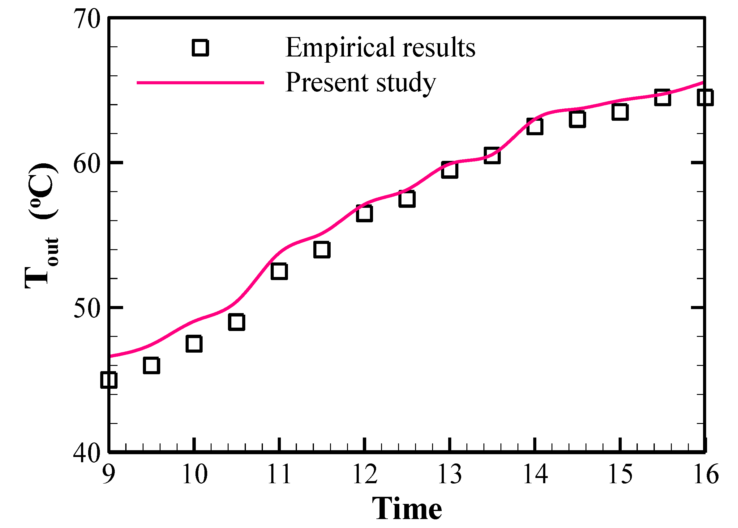
Computer software validation was performed using the method of Khorasanizadeh et al. [36]. In their study, the properties of an FPSC were evaluated by empirical measurements. Based on Figure 2, it is clear that there is a remarkable coincidence between the empirical [36] and numerical results in terms of the outlet temperature of the fluid. The maximum error between empirical and numerical results in Figure 2 is about 12.5% at 9 a.m.

3. Results

In this section, first, the FPSC exergy analysis is presented in two different conditions, and then the optimization case is investigated.

3.1. Energy and Exergy Analysis

The total heat loss coefficient, mean temperature of the absorber plate, FPSC outlet temperature, and energy and exergy efficiencies of a simple FPSC (with circular tubes) and of a novel FPSC equipped with elliptical tubes at different hours of the day are reported in Table 4 and Table 5, respectively. All of these values are based on numerical results and analytical correlation.
It is clear that the energy and exergy efficiencies of the novel FPSC increase by about 30% and 60%, respectively, compared with the reference FPSC, owing to the more wetted surface between the plate and fluid. Furthermore, the mean temperature of the plate and the outlet temperature of the FPSC continuously increase during the day because of the FPSC inlet temperature of the fluid that is taken from the reservoir and which is constantly increasing due to FPSC performance in a closed loop and due to the heat retained in the reservoir. Furthermore, in all conditions, the inlet radiation flux rate rises from morning to midday hours and then diminishes. The energy efficiency has the same trend. However, the reason for the decreasing energy efficiency after the afternoon hours is the increasing inlet fluid temperature and also the increasing temperature of the absorber plate as time passes, which intensifies the losses.
It is clear from Table 4 and Table 5 that the change in UL in different hours is significant, so in the condition of the FPSC with a simple heat sink, the relative difference between UL at 10:00 and that at 16:00 is about 9%. This difference is greater than that in other cases. This fact shows that the assumption of constant UL, as some researchers have considered, is not valid [12], and it is necessary to apply its changes in measurements. Therefore, it is clear that the usage of the novel FPSC with elliptical tubes may lead to more energy and exergy efficiencies. Hence, in the next sections, the employment of an NF in a novel FPSC is analyzed.

3.2. Using a Nanofluid and Exergetic Optimization

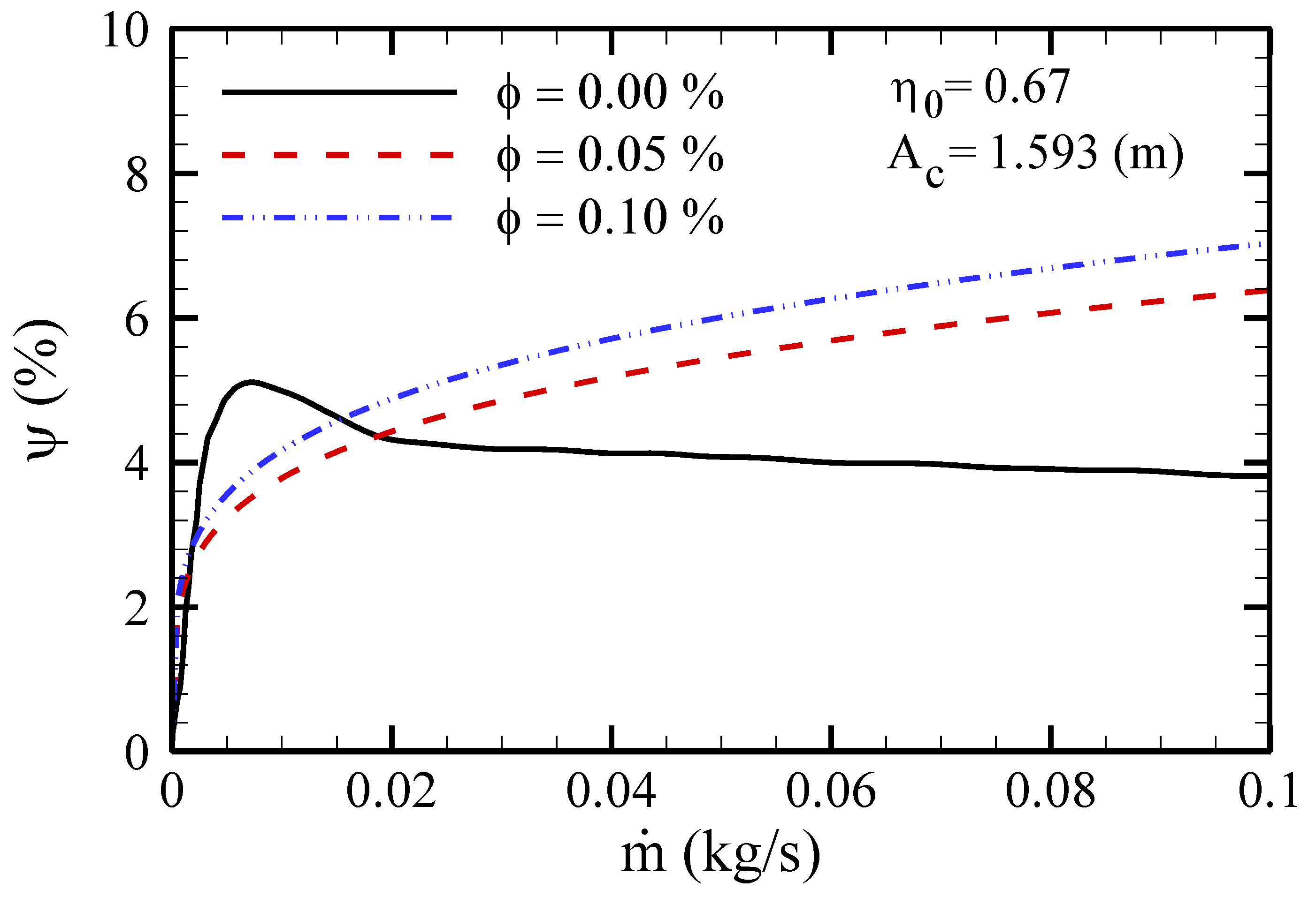
For both conditions in which the FPSC is used, the lowest exergy and energy values are observed at 9 a.m., and both energy efficiency and exergy efficiency are dependent on the IT and radiation angle. At 9 a.m., the IT is less, and the angle between the direct sun radiation horizon and the vertical to the FPSC surface is high. Hence, the sun radiation absorption is less. In addition, the FPSC performance, due to the change in IT and radiation angle, and the change in temperature of the FPSC inlet water are always transient. These conditions are of high importance in the early hours of the day and are factors that decrease efficiency. The effect of changing Ta, IT, Tin, η0, and parameters on exergy efficiency in different φ for the optimal condition (novel FPSC) at this time was studied to optimize the FPSC from the exergy viewpoint. Therefore, when different values were considered for one parameter, the value at 9 a.m. was assigned to other parameters. The results related to the influence of changing various parameters on the exergy analysis are shown in Figure 3, Figure 4, Figure 5, Figure 6 and Figure 7.
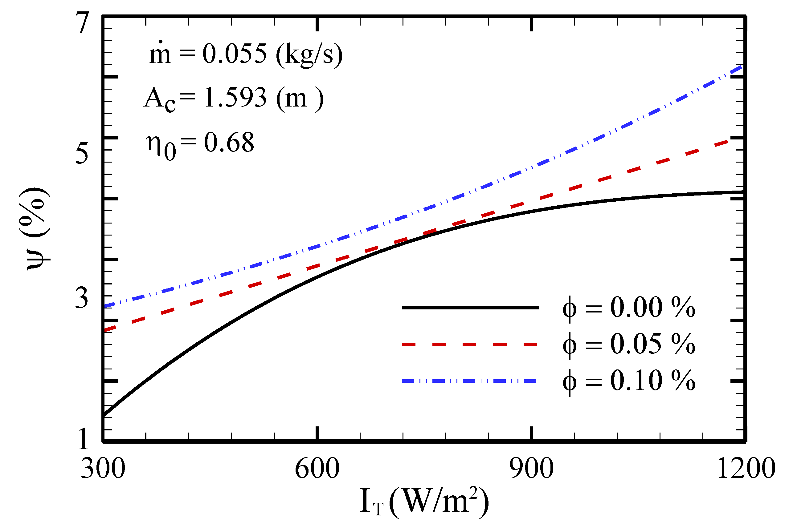
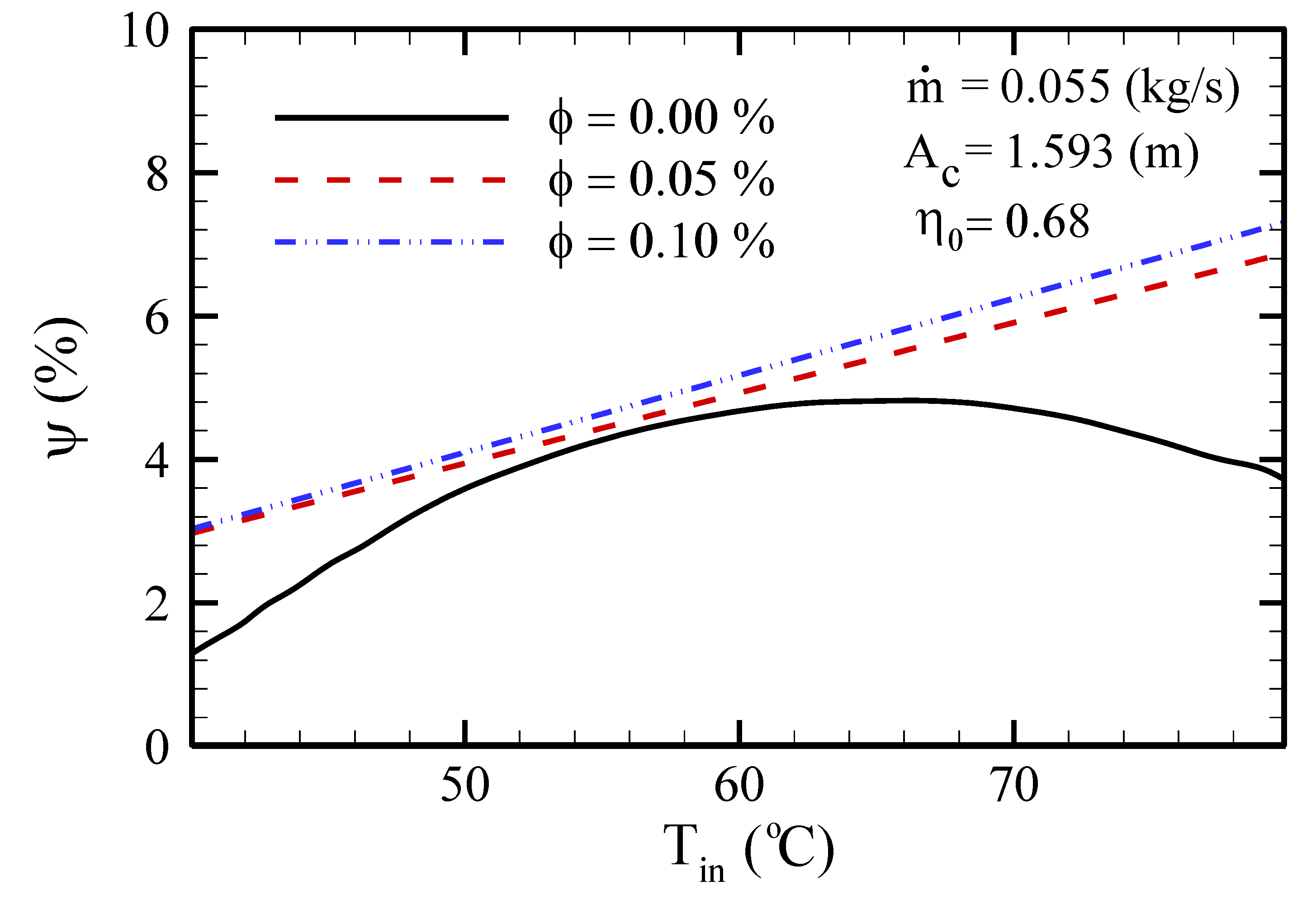
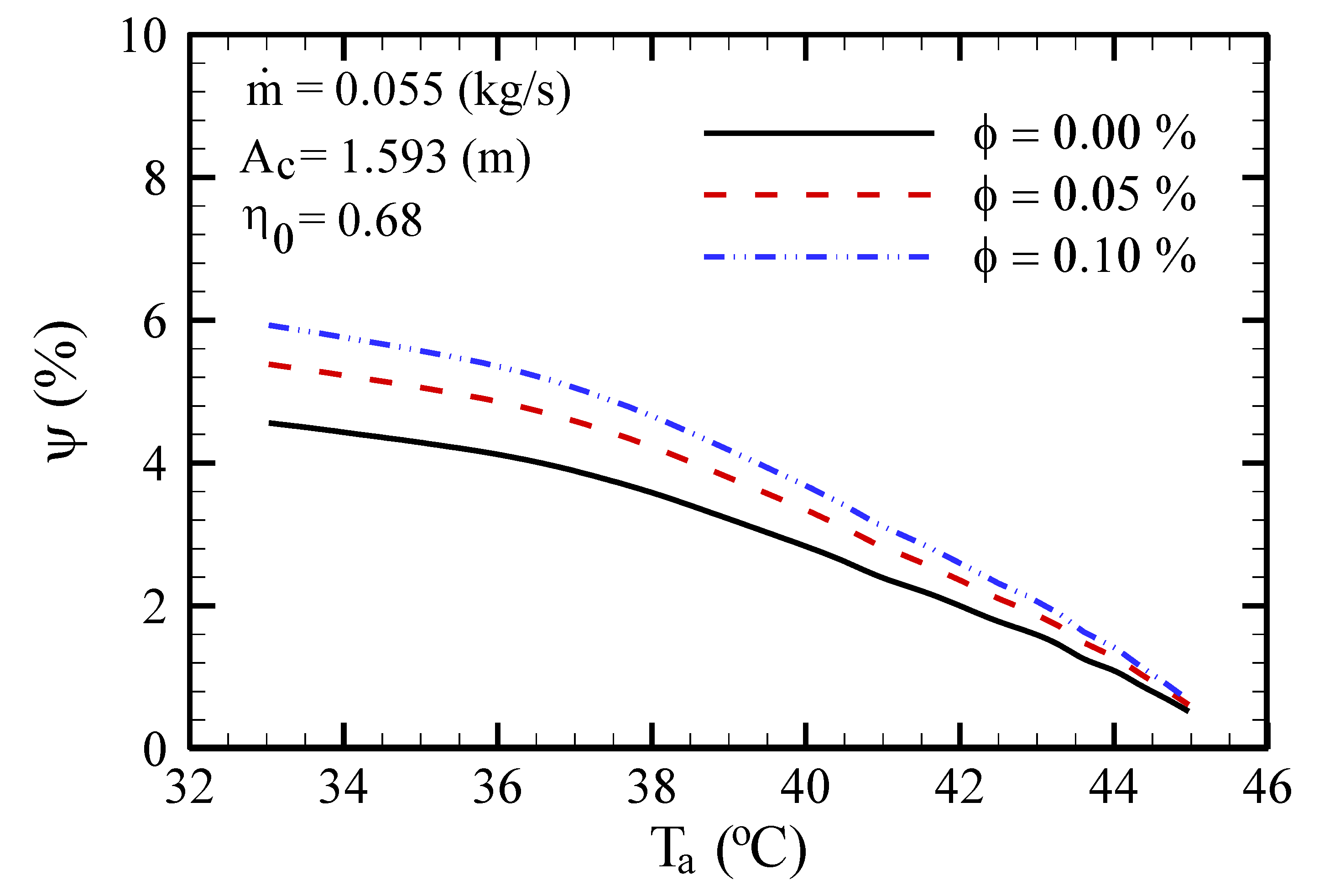
In Figure 3, the exergy efficiency variation with sun radiation flux for different ϕ is shown. In the period of changing radiation flux, from 300 to 1200 W/m2, for all conditions, an increasing trend for the exergy value is observed. With increasing radiation of the sun, the temperature of FPSC outlet fluid rises, and this increase leads to an exergy efficiency increase. The exergy efficiency variation with FPSC inlet fluid temperature for different ϕ is demonstrated in Figure 4. For base fluid conditions, the exergy efficiency first increases until the temperature reaches 65–70 °C, and then it decreases. On the one hand, with Tin intensification, the outlet temperature rises, which leads to an exergy efficiency increase. On the other hand, Tin intensification means that the fluid temperature inside the FPSC increases, which raises the thermal loss. Therefore, there is one optimum Tin, and above this temperature, the effect of exergy efficiency reduction due to higher thermal loss is greater than its increase because of the increased fluid outlet temperature. However, for NF conditions, the exergy efficiency rises in response to the increased inlet temperature. The variation in exergy efficiency with ambient temperature for different ϕ is shown in Figure 5. For all three conditions, exergy efficiency decreases as ambient temperature increases. In this figure, the effect of using mixers on increasing exergy efficiency due to the heat transfer rate between the fluid and FPSC is perfectly clear. In Figure 6, the influence of increasing optical efficiency on exergy efficiency for different ϕ is demonstrated. By increasing optical efficiency for all three FPSC conditions, radiation absorption by the absorber plate is enhanced, which causes the fluid temperature inside the FPSC to rise, and therefore, the exergy efficiency rises. In Figure 7, the effect of changing the fluid mass flow rate passing through the FPSC is shown for different mass flow rates from 0.0 to 0.1 kg/s. The applied mass flow rate for three conditions was about 0.055 kg/s. From the results presented in Figure 7, it is understood that in the simulation conditions, parameters such as ambient temperature, inlet fluid temperature, optical efficiency, radiate flux, and FPSC cross-section have the same values as those in Table 4 and Table 5, which are observed at 9:00 a.m. For the FPSC with the base fluid, the optimum mass flow rate that causes the maximum exergy efficiency should be 10 times lower, i.e., 0.005 kg/s. Consequently, the exergy efficiency is 5.3% instead of 4%. Nevertheless, for the condition in which the NF is used, the maximum exergy efficiency occurs with the highest mass flow rate of 0.1 kg/s.
Finally, the novel FPSC equipped with elliptical tubes and filled with the water-based NF (φ = 0.10%) is suggested as the optimum case, with maximum exergy efficiencies in almost all ranges of flow velocities in the present investigation.
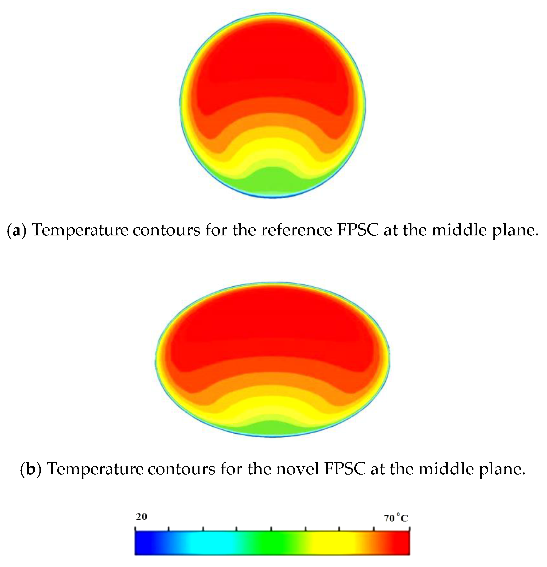
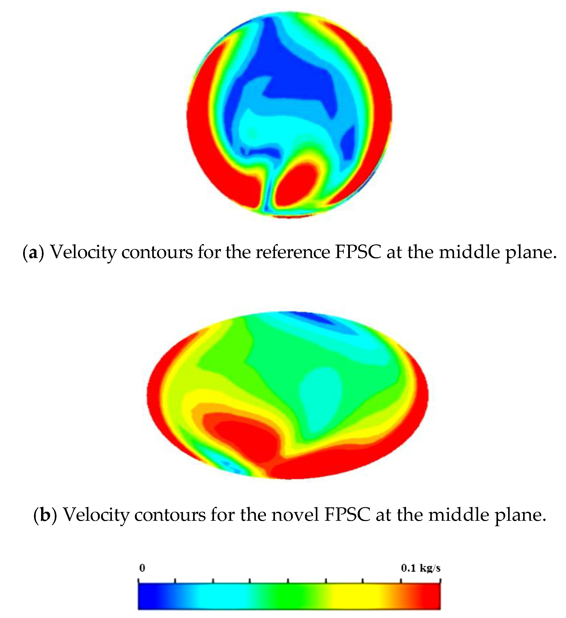
Figure 8 illustrates temperature contours for the reference and novel FPSC filled with the NF at the middle plane. As observed in this figure, in the case of using elliptical tubes, the heat diffusion in the pipes is clearly increased. Furthermore, Figure 9 shows velocity contours for the reference and novel FPSC filled with the NF at the middle plane.

4. Conclusions

In this contribution, we studied the optimization of a novel FPSC equipped with elliptical tubes in a closed circuit for three conditions from the viewpoint of exergy analysis by assuming that UL is the only variable parameter and that the fluid temperature is not equal to ambient temperature. The effects of using elliptical tubes instead of circular ones and of using an NF through a fluid passage were studied, and the following results were obtained:
  • An increase in solar radiation flux and optical efficiency entails an exergy efficiency increase for all conditions.
  • The exergy efficacy diminishes as ambient temperature increases, but by increasing the FPSC inlet fluid temperature, the exergy efficacy rises to a certain temperature and then declines.
  • With the use of an NF, the exergy efficiency always intensifies with a boost of inlet temperature.
  • For higher mass flow rates of the base fluid, the efficiency first slightly declines and then remains unchanged. However, by using an NF, the maximum exergy efficiency occurs with the highest mass flow rate.
  • Generally, using elliptical tubes and an NF enhances the exergy efficiency. In fact, while the trend of exergy efficiency variation with effective parameters is increasing, applying the elliptical tubes causes the efficiency to increase.
  • The temperature increase entails an exergy efficiency increase to a certain point, and then this efficiency is diminished for higher values.

Author Contributions

Conceptualization, S.R. and A.S.G.; methodology, M.S.; software, A.D. and A.K.H.; validation, A.K.H.; formal analysis, A.S.G.; investigation, S.R.; resources, A.K.H.; data curation, M.S.; writing—original draft preparation, S.R. and A.S.G.; writing—review and editing, S.R. and A.S.G.; visualization, A.D.; supervision, A.S.G. and M.S.S.; All authors have read and agreed to the published version of the manuscript.

Funding

This research received no external funding.

Conflicts of Interest

There is no conflict of interest.

Nomenclature

Aarea (m2)
cpspecific heat capacity (J kg−1 K−1)
Ėrate of exergy (W)
hwwind convection coefficient (W m−2)
Isolar intensity (W m−2)
Ibbeam radiation (W m−2)
Iddiffuse radiation (W m−2)
ITdaily average hourly (W m−2)
Ivspectral radiation intensity (W m−2)
Kthermal conductivity (W m−1 K−1)
Mmass flow rate (kg s−1)
Nnumber of glass covers
Ppressure (Pa)
Ppumppumping power (W)
Ssection of solar radiation (W m−2)
Ttemperature (K)
Taambient temperature (K)
Tpmmean temperature of absorber plate
Uvelocity (m s−1)
u’fluctuated velocity (m s−1)
Utotal loss coefficient (W m−2 K−1)
Vwwind speed (m s−1)
Greek symbol
αabsorption coefficient
εemission coefficient or dissipation
ηEfficiency
η0optical efficiency of collector
µviscosity (kg m−1 s−1)
μtturbulent viscosity (kg m−1 s−1)
ρdensity (kg m−3)
σStefan–Boltzmann constant (W m−2 K−4)
φlatitude angle
Ωhour angle
Subscripts
aambient
ccollector
ffluid
ininlet
outoutlet
pabsorbent plate

References

  1. Tian, M.-W.; Ebadi, A.G.; Jermsittiparsert, K.; Kadyrov, M.; Ponomarev, A.; Javanshir, N.; Nojavan, S. Risk-based stochastic scheduling of energy hub system in the presence of heating network and thermal energy management. Appl. Therm. Eng. 2019, 159, 113825. [Google Scholar] [CrossRef]
  2. Tian, M.-W.; Yuen, H.-C.; Yan, S.-R.; Huang, W.-L. The multiple selections of fostering applications of hydrogen energy by integrating economic and industrial evaluation of different regions. Int. J. Hydrog. Energy 2019, 44, 29390–29398. [Google Scholar] [CrossRef]
  3. Shenoy, D.V.; Shadloo, M.S.; Hadjadj, A.; Peixinho, J. Direct numerical simulations of laminar and transitional flows in diverging pipes. Int. J. Numer. Methods Heat Fluid Flow 2019, 30. [Google Scholar] [CrossRef]
  4. Tian, M.-W.; Yan, S.-R.; Tian, X.-X.; Kazemi, M.; Nojavan, S.; Jermsittiparsert, K. Risk-involved stochastic scheduling of plug-in electric vehicles aggregator in day-ahead and reserve markets using downside risk constraints method. Sustain. Cities Soc. 2020, 55, 102051. [Google Scholar] [CrossRef]
  5. Tian, M.-W.; Parikhani, T.; Jermsittiparsert, K.; Ashraf, M.A. Exergoeconomic optimization of a new double-flash geothermal-based combined cooling and power (CCP) system at two different cooling temperatures assisted by boosters. J. Clean. Prod. 2020, 261, 120921. [Google Scholar] [CrossRef]
  6. Tian, M.-W.; Wang, L.; Yan, S.-R.; Tian, X.-X.; Liu, Z.-Q.; Rodrigues, J.J.P.C. Research on Financial Technology Innovation and Application Based on 5G Network. IEEE Access 2019, 7. [Google Scholar] [CrossRef]
  7. Tian, M.; Yan, S.; Tian, X. Discrete approximate iterative method for fuzzy investment portfolio based on transaction cost threshold constraint. Open Phys. 2019, 17, 41–47. [Google Scholar] [CrossRef]
  8. Li, Z.; Shahsavar, A.; Niazi, K.; Al-Rashed, A.A.A.A.; Rostami, S. Numerical assessment on the hydrothermal behavior and irreversibility of MgO-Ag/water hybrid nanofluid flow through a sinusoidal hairpin heat-exchanger. Int. Commun. Heat Mass Transf. 2020, 115, 104628. [Google Scholar] [CrossRef]
  9. Pordanjani, A.H.; Aghakhani, S.; Afrand, M.; Mahmoudi, B.; Mahian, O.; Wongwises, S. An updated review on application of nanofluids in heat exchangers for saving energy. Energy Convers. Manag. 2019, 198, 111886. [Google Scholar] [CrossRef]
  10. Ghalandari, M.; Maleki, A.; Haghighi, A.; Shadloo, M.S.; Nazari, M.A.; Tlili, I. Applications of nanofluids containing carbon nanotubes in solar energy systems: A review. J. Mol. Liq. 2020, 313, 113476. [Google Scholar] [CrossRef]
  11. Shahsavar, A.; Khanmohammadi, S.; Afrand, M.; Shahsavar, A.; Rostami, S. On evaluation of magnetic field effect on the formation of nanoparticles clusters inside aqueous magnetite nanofluid: An experimental study and comprehensive modeling. J. Mol. Liq. 2020, 312, 113378. [Google Scholar] [CrossRef]
  12. Rostami, S.; Shahsavar, A.; Kefayati, G.R.; Goldanlou, S.A. Energy and Exergy Analysis of Using Turbulator in a Parabolic Trough Solar Collector Filled with Mesoporous Silica Modified with Copper Nanoparticles Hybrid Nanofluid. Energies 2020, 13, 2946. [Google Scholar] [CrossRef]
  13. Tian, Z.; Shahsavar, A.; Al-Rashed, A.A.A.A.; Rostami, S. Numerical simulation of nanofluid convective heat transfer in an oblique cavity with conductive edges equipped with a constant temperature heat source: Entropy production analysis. Comput. Math. Appl. 2019, in press. [Google Scholar] [CrossRef]
  14. Baniamerian, Z.; Mehdipour, R.; Kargar, F. A numerical investigation on aerodynamic coefficients of solar troughs considering terrain effects and vortex shedding. Int. J. Eng. Trans. C Asp. 2015, 28, 940–948. [Google Scholar]
  15. Ziapour, B.M.; Rahimi, F. Numerical study of natural convection heat transfer in a horizontal wavy absorber solar collector based on the second law analysis. Int. J. Eng. Trans. A Basics 2016, 29, 109–117. [Google Scholar]
  16. Ajay, K.; Kundan, L. Performance evaluation of nanofluid (Al2O3/H2O-C2H6O2) based parabolic solar collector using both experimental and CFD techniques. Int. J. Eng. Trans. A Basics 2016, 29, 572–580. [Google Scholar]
  17. Luminosu, I.; Fara, L. Determination of the optimal operation mode of a flat solar collector by exergetic analysis and numerical simulation. Energy 2005, 30, 731–747. [Google Scholar] [CrossRef]
  18. Shojaeizadeh, E.; Veysi, F. Development of a correlation for parameter controlling using exergy efficiency optimization of an Al2O3/water nanofluid based flat-plate solar collector. Appl. Therm. Eng. 2016, 98, 1116–1129. [Google Scholar] [CrossRef]
  19. Said, Z.; Saidur, R.; Rahim, N.A. Energy and exergy analysis of a flat plate solar collector using different sizes of aluminium oxide based nanofluid. J. Clean. Prod. 2016, 133, 518–530. [Google Scholar] [CrossRef]
  20. Hussein, A.K.; Kolsi, L.; Almeshaal, M.A.; Li, D.; Ali, H.M.; Ahmed, I.S. Mixed Convection in a Cubical Cavity with Active Lateral Walls and Filled with Hybrid Graphene–Platinum Nanofluid. J. Therm. Sci. Eng. Appl. 2019, 11, 041007. [Google Scholar] [CrossRef]
  21. RazaShah, T.; Ali, H.M. Applications of hybrid nanofluids in solar energy, practical limitations and challenges: A critical review. Sol. Energy 2019, 183, 173–203. [Google Scholar]
  22. UsmanSajid, M.; Ali, H.M. Recent advances in application of nanofluids in heat transfer devices: A critical review. Renew. Sustain. Energy Rev. 2019, 103, 556–592. [Google Scholar]
  23. Ali, H.M. Recent advancements in PV cooling and efficiency enhancement integrating phase change materials based systems—A comprehensive review. Sol. Energy 2020, 197, 163–198. [Google Scholar] [CrossRef]
  24. Shadloo, M.S. Numerical Simulation of Compressible Flows by Lattice Boltzmann Method. Numer. Heat Transf. Part A 2019, 75, 167–182. [Google Scholar] [CrossRef]
  25. Kassem, Y.; Çamur, H.; Aateg, R.A.F. Exploring Solar and Wind Energy as a Power Generation Source for Solving the Electricity Crisis in Libya. Energies 2020, 13, 3708. [Google Scholar] [CrossRef]
  26. Ahmed, S.; Muhammad Adil, H.M.; Ahmad, I.; Azeem, M.K.; e Huma, Z.; Abbas Khan, S. Supertwisting Sliding Mode Algorithm Based Nonlinear MPPT Control for a Solar PV System with Artificial Neural Networks Based Reference Generation. Energies 2020, 13, 3695. [Google Scholar] [CrossRef]
  27. Lee, Y.; Kim, B.; Hwang, H. Which Institutional Conditions Lead to a Successful Local Energy Transition? Applying Fuzzy-Set Qualitative Comparative Analysis to Solar PV Cases in South Korea. Energies 2020, 13, 3696. [Google Scholar] [CrossRef]
  28. Shaaban, M.F.; Alarif, A.; Mokhtar, M.; Tariq, U.; Osman, A.H.; Al-Ali, A.R. A New Data-Based Dust Estimation Unit for PV Panels. Energies 2020, 13, 3601. [Google Scholar] [CrossRef]
  29. Araújo, A. Thermo-Hydraulic Performance of Solar Air Collectors with Artificially Roughened Absorbers: A Comparative Review of Semi-Empirical Models. Energies 2020, 13, 3536. [Google Scholar] [CrossRef]
  30. Dijvejin, Z.A.; Ghaffarkhah, A.; Sadeghnejad, S.; Sefti, V. Effect of silica nanoparticle size on the mechanical strength and wellbore plugging performance of SPAM/chromium (III) acetate nanocomposite gels. Polym. J. 2019, 51, 693–707. [Google Scholar] [CrossRef]
  31. Ghaffarkhah, A.; Afrand, M.; Talebkeikhah, M.; Sehat, A.A.; Moraveji, M.K.; Talebkeikhah, F.; Arjmand, M. On evaluation of thermophysical properties of transformer oil-based nanofluids: A comprehensive modeling and experimental study. J. Mol. Liq. 2020, 300, 112249. [Google Scholar] [CrossRef]
  32. Parsa, S.M.; Davoud, J.Y.; Rahbar, A.; Majidniya, M.; Aberoumand, S.; Amidpour, Y.; Amidpour, M. Experimental assessment on passive solar distillation system on Mount Tochal at the height of 3964 m: Study at high altitude. Desalination 2019, 466, 77–88. [Google Scholar] [CrossRef]
  33. Parsa, S.M.; Davoud, J.Y.; Rahbar, A.; Majidniya, M.; Aberoumand, S.; Amidpour, Y.; Amidpour, M. Experimental investigation at a summit above 13,000 ft on active solar still water purification powered by photovoltaic: A comparative study. Desalination 2020, 476, 114146. [Google Scholar] [CrossRef]
  34. Parsa, S.M.; Rahbar, A.; Davoud, J.Y.; Koleini, M.H.; Afrand, M.; Amidpour, M. Energy-matrices, exergy, economic, environmental, exergoeconomic, enviroeconomic, and heat transfer (6E/HT) analysis of two passive/active solar still water desalination nearly 4000m: Altitude concept. J. Clean. Prod. 2020, 261, 121243. [Google Scholar] [CrossRef]
  35. Parsa, S.M.; Rahbar, A.; Koleini, M.H.; Aberoum, S.; Afrand, M.; Amidpour, M. Desalination, A renewable energy-driven thermoelectric-utilized solar still with external condenser loaded by silver/nanofluid for simultaneously water disinfection and desalination. Desalination 2020, 480, 114354. [Google Scholar] [CrossRef]
  36. Khorasanizadeh, H.; Aghaie, A. Determination of the monthly, seasonal, semi-yearly and yearly optimum tilted angles of flat plate solar collectors in Kashan. J. Energy Eng. Manag. 2014, 3, 38–49. [Google Scholar]
  37. Sadeghi, R.; Shadloo, M.S.; Hooman, K. Numerical Investigation of Natural Convection Film Boiling Around Elliptical Tubes. Numer. Heat Transf. Part A Appl. 2016, 70, 707–722. [Google Scholar] [CrossRef]
  38. Vanaki, S.M.; Mohammed, H.A.; Abdollahi, A.; Wahid, M.A. Effect of nanoparticle shapes on the heat transfer enhancement in a wavy channel with different phase shifts. J. Mol. Liq. 2014, 196, 32–42. [Google Scholar] [CrossRef]
  39. Gray, D.D.; Giorgini, A. The validity of the Boussinesq approximation for liquids and gases. Int. J. Heat Mass Transf. 1976, 19, 545–551. [Google Scholar] [CrossRef]
  40. ANSYS Fluent-Solver Theory Guide; Release 14.0; ANSYS Inc.: Canonsburg, PA, USA, 2011; pp. 351–353.
  41. Bejan, A. Convection Heat Transfer; Wiley-Interscience: Hoboken, NJ, USA, 1984. [Google Scholar]
  42. Duffie, J.A.; Beckman, W.A. Solar Engineering of Thermal Processes; John Wiley & Son: New York, NY, USA, 2006. [Google Scholar]
  43. Mechanical Agitator Power Requirements for Liquid. Available online: www.pdhonline.com/courses/k103/k103content.pdf (accessed on 12 August 2020).
  44. Suzuki, A. General theory of exergy balance analysis and application to solar collectors. Energy 1988, 13, 123–160. [Google Scholar] [CrossRef]
  45. Bejan, A.; Keary, D.W.; Kreith, F. Second law analysis and synthesis of solar collector systems. J. Sol. Energy Eng. 1981, 103, 23–28. [Google Scholar] [CrossRef]
  46. Bejan, A. Advanced Engineering Thermo-Dynamics; Wiley Inter science: New York, NY, USA, 1988. [Google Scholar]
  47. Dutta Gupta, K.K.; Saha, S. Energy analysis of solar thermal collectors. Renew. Energy Environ. 1990, 33, 283–287. [Google Scholar]
  48. Kahrobaian, A.; Malekmohammadi, H. Exergy optimization applied to linear parabolic solar collectors. J. Fac. Eng. 2008, 42, 131–144. [Google Scholar]
  49. Farahat, S.; Sarhaddi, F.; Ajam, H. Exergetic Optimization of Flat Plate Solar Collectors. Renew. Energy 2009, 34, 1169–1174. [Google Scholar] [CrossRef]
  50. Patel, H.E.; Anoop, K.B.; Sundararajan, T.; Das, S. Model for thermal conductivity of CNT-nanofluids. Bull. Mater. Sci. 2008, 31, 387–390. [Google Scholar] [CrossRef]
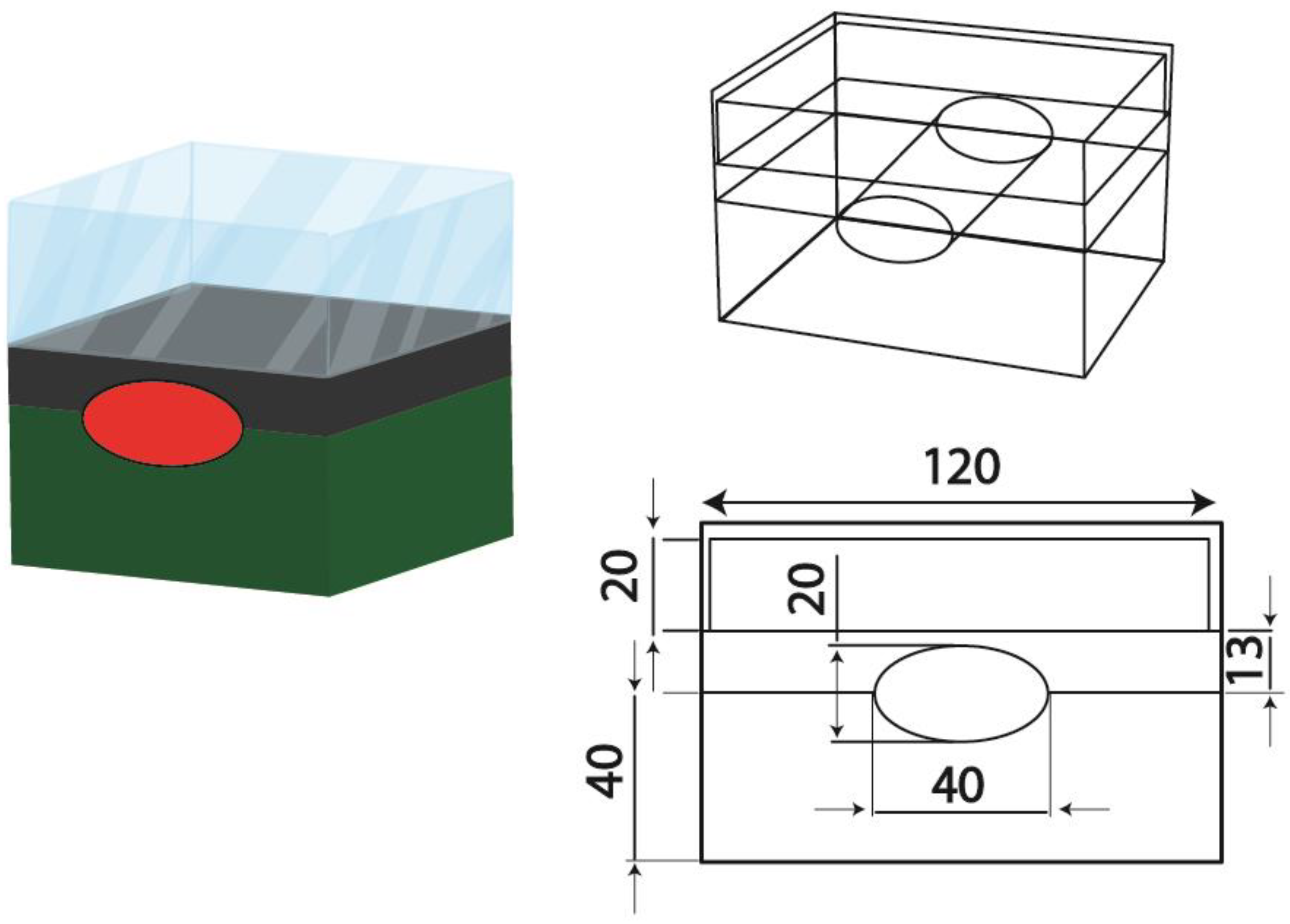
Figure 1. Schematic of the problem.
Water 12 02294 g001
Figure 2. Comparison between the results of this study with the empirical results of Khorasanizadeh et al. [36] in terms of outlet fluid temperature.
Water 12 02294 g002
Figure 3. Variation in exergy efficiency of the novel FPSC with solar radiation in terms of ϕ.
Water 12 02294 g003
Figure 4. Variation in exergy efficiency of the novel FPSC with Tin in terms of φ.
Water 12 02294 g004
Figure 5. Variation in exergy efficiency of the novel FPSC using a nanofluid (NF) with ambient temperature in terms of φ.
Water 12 02294 g005
Figure 6. Variation in exergy efficiency of the novel FPSC with optical efficiency versus ϕ.
Water 12 02294 g006
Figure 7. Variation in exergy efficiency of the novel FPSC with mass flow rate in terms of φ.
Water 12 02294 g007
Figure 8. Temperature contours for the FPSC filled with the NF at the middle plane.
Water 12 02294 g008
Figure 9. Velocity contours for the FPSC filled with the NF at the middle plane.
Water 12 02294 g009
Table 1. Properties of the flat plate solar collector (FPSC) simulated in this paper.
PropertiesSymbolQuantity
Dimensions of FPSCLc × Wc (mm)200 × 92.5
Slop of FPSCβ35°
Number of glass coversN1
Emissivity of glass coversεg0.85
Thickness of plateδp (mm)0.1
Emissivity of plateεp0.9
Conductivity of platekp (W·m−1·K−1)211
Optical efficiencyη00.68
Thickness of insulatorsδi (mm)2.0
Conductivity of insulatorski (W·m−1·K−1)0.05
Table 2. Empirical results of Khorasanizadeh et al. [36] for the reference FPSC.
TimeIT (W·m−2)Ta (°C)Tin (°C)Vw (m·s−1)
09:005603344.56
09:3063033456
10:0075034465
10:3083035476
11:0092536506
11:3099237515
12:00100638535
12:30102038.5546
13:0097840.5566
13:3091440.5575
14:0083441605
14:3078041614
15:0073439.5625
15:3062641636
16:0060741646
Table 3. Grid independence test.
NodesTout (°C)Error (%)
3,243,98366.67822.22
3,599,00770.51341.05
3,728,62370.78110.02
3,954,13170.7834-
Table 4. Results of reference solar FPSC.
TimeUL (W/m2·K)Tpm (°C)Tout (°C)η (%)ψ (%)
09:007.3348.1158.5954.293.34
09:307.3749.0659.6157.483.53
10:007.3251.3261.0457.783.95
10:307.4952.4162.6164.404.21
11:007.5654.2565.8263.004.35
11:307.5257.0767.0763.684.58
12:007.5658.4269.2361.914.60
12:307.7759.3170.2661.544.55
13:007.7660.4672.0461.484.54
13:307.4060.5772.6160.164.68
14:007.7363.2275.1358.644.67
14:307.5563.4775.7757.574.56
15:007.7763.8976.4156.914.41
15:307.9464.0976.9156.284.21
16:007.9765.1177.8255.624.15
Table 5. Results of novel FPSC.
TimeUL (W/m2·K)Tpm (°C)Tout (°C)η (%)ψ (%)
09:007.1547.0853.2364.046.34
09:307.2148.0254.2467.836.88
10:007.0850.2755.5168.187.77
10:307.2551.3357.4975.988.34
11:007.3253.2159.6174.348.71
11:307.3556.0062.2976.449.21
12:007.3457.3263.7174.289.98
12:307.5158.1464.4073.818.75
13:007.5659.3265.8773.788.62
13:307.3059.5266.0172.788.93
14:007.6062.1368.8269.148.87
14:307.3862.4268.9969.088.81
15:007.5962.6469.1166.588.51
15:307.6763.0169.2565.848.01
16:007.6964.1269.3465.637.88