Article

The Effects of Exchange Flow on the Karst Spring Hydrograph under the Different Flow Regimes: A Synthetic Modeling Approach

1
Department of Earth Sciences, Faculty of Sciences, Shiraz University, Shiraz 7146713565, Iran
2
HydroSciences Montpellier (HSM), Université de Montpellier, CNRS, IRD, 34090 Montpellier, France
3
Géosciences Environnement, Université Toulouse, Toulouse-CNRS-UPS-IRD, 31400 Toulouse, France
*
Author to whom correspondence should be addressed.
Water 2021, 13(9), 1189; https://doi.org/10.3390/w13091189
Submission received: 22 March 2021 / Revised: 15 April 2021 / Accepted: 21 April 2021 / Published: 25 April 2021
(This article belongs to the Special Issue Methods and Tools for Assessment of Groundwater)

Abstract

:
In this study, a synthetic modeling approach is proposed to quantify the effect of the amount and direction of the exchange flow on the karstic spring discharge fluctuations under different hydrologic conditions corresponding to high and low flow conditions. We hypothesis that the spring discharge fluctuations constitute a valuable proxy to understand the internal processes of the karst system. An ensemble of spring hydrographs was synthetically produced to highlight the effect of exchange flow by exploring the plausible range of variability of coefficients of exchange flow, conduit diameter, and matrix hydraulic conductivity. Moreover, the change of the rate of point recharge through the karst conduit allows for the quantifying of the sensibility of the spring hydrograph to the directions of exchange flow. We show that increasing the point recharge lies to a remarkable linear recession coefficient (β) as an indication of the conduit flow regime. However, a reduction in and/or lack of the point recharge caused the recession coefficient to change to exponential (α) due to the dominant effect of the matrix restrained flow regime and/or conduit-influenced flow regime. The simulations highlight that the exchange flow process from the conduit to the matrix occurred in a short period and over a restricted part of the conduit flow regime (CFR). Conversely, the exchange flow dumped from the matrix to the conduit occurs as a long-term process. A conceptual model is introduced to compare spring hydrographs’ characteristics (i.e., the peak discharge, the volume of baseflow, and the slope of the recession curve) under the various flow conditions with the directions of the exchange flow between the conduit and the matrix.

1. Introduction

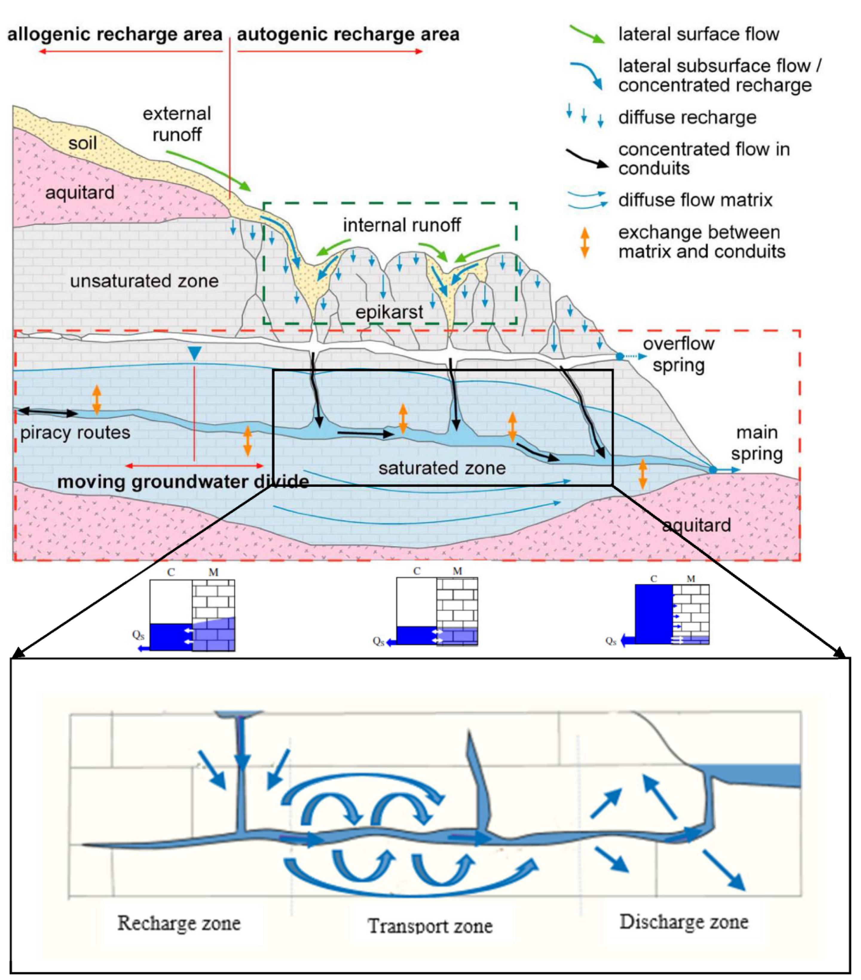
Karst aquifers can be considered as a “dual-porosity” or “dual-permeability” media (Figure 1) that include (1) matrix porosity comprising intergranular pores and the small joints with high storage capacity and low velocity, and (2) conduit porosity comprising enlarged, dissolved, and unclogged fractures with low storage capacity and high flow velocity [1]. Karst aquifers are characterized by a strong physical heterogeneity and may present strong anisotropy in terms of hydrodynamic properties such as hydraulic conductivity and specific storage due to a complex and three-dimensional dissolution development [2].
These conditions imply an inherent duality in all processes governing the hydrological response of the karst system, including (1) the infiltration and recharge processes which range from diffusive and slow recharge into the matrix to rapid and concentrated recharge into the conduit through features such as sinkholes, sinking streams, and ponor caves, (2) the flow regime changes between the two endpoints with slow velocity in the matrix and fast flow velocity in the karst conduits, and (3) mechanism of discharge that ranges from low and continuous discharge during dry periods (dominant matrix flow) to high and rapid discharge with high temporal variability during the rainfall events (conduit flow regime) [3].
Generally, the hydraulic gradient between the matrix and conduit leads to an exchange flow between the matrix and the karst conduit network [4]. The matrix may be alternatively recharged or drained by conduits depending on the occurrence of recharge events and the respective flow dynamics in the conduit and matrix. This process is known as the hydraulic gradient inversion [5]. The rate of this exchange flow depends on the hydraulic gradient between the matrix and the conduit. Moreover, due to the inherent heterogeneity and anisotropy of karst aquifers, the exchange flow is often variable in both temporal and spatial spaces [6].
The behavior of exchange flow and governing equations have previously been studied from different points of views including (1) the theoretical formulation of the exchange coefficient and the exchange flow [7,8,9,10], (2) the investigation of steady and unsteady exchange flows as a result of the temporal changes in the pressure gradient between matrix and conduit [11,12], (3) the calibration and optimization of the exchange coefficient [13], (4) the estimation of the volume of exchange flow and infiltration into the matrix [14], (5) the investigation of the influence of the exchange flow direction on the karstification process [15] and the different flow regimes in karst aquifers [16], (6) the investigation of the spatial changes of the exchange flow throughout conduits [17], and finally, (7) the investigation of the dependence of exchange flow on the geometry of the conduit network and its effect on the discharge and the shape of karst springs hydrograph [18,19]. Moreover, the exchange flow is generally considered as the interaction between the matrix and the conduit through karst modeling studies for different purposes [20,21,22,23,24,25].
Several researchers highlighted the impact of the exchange flow and its direction in various hydrogeological issues. Bailly-Comte et al. [16] highlighted a rapid transport of pollutants to the spring outlet without significant dilution if the exchange flow is limited while a low level of pollutants is expected considering dilution and sorption of pollutants as well as the active exchange flow. These concerns are very important in coastal aquifers. For example, Peterson et al. [26] showed along the western coast of the Big Island of Hawaii, where groundwater is the only link between land and the ocean and often focused as point-source discharges [27], that any contamination could affect local coastal ecologies including coral reefs. Frank et al. [28] studied a complex gypsum carbonate karst system and showed that the direction of exchange flow changed during high-flow and low-flow conditions by determining the origin and chemical composition of the spring water. They concluded that the direction of the exchange flow is from conduits toward the matrix due to the high contribution of carbonate layers in the spring water during recharge events. However, the direction of the exchange flow reversed during the low-flow conditions because the spring water is supplied by the matrix of gypsum. Interestingly, the development of the dissolution conduits may be accelerated by the exchange flow. Since water in conduits is potentially aggressive, the exchange flow from conduits to the matrix can facilitate the dissolution processes and development of karst. However, when the exchange flow is from the matrix to the conduit, exchange water is often saturated concerning calcite, therefore, no significant dissolution occurs [15]. Duran et al. [29], by studying the Norville karst system located in Normandy (France), showed that the electrical Conductivity (EC) of the karst spring varies between 500 and 300 μS/cm. The exchange flow from the matrix to the conduit and EC show similar variations and increases in the absence of rainfall events. However, during rainfall events, the volume of exchange flow from the conduit to the matrix increases, and the EC decreases.
Hill [30] compared the performance of different models concerning the importance of exchange flow in the modeling processes of the karst aquifer at a test-site near Weeki Wachee, Florida, in the dual permeability Upper Floridian aquifer. Based on their results, the dual-permeability model using the MODFLOW-2005 CFP Mode 1 due to the importance of exchange flow in its modeling process displayed improved matches ranging from 12 to 40% between simulated and observed discharges relative to the laminar and laminar/turbulent equivalent continuum models. Moreover, Joodi et al. [31] used the analysis of dye tracer test results to compare two models of Darcy-Darcy and the Darcy-Brinkman in the karst aquifer located in Val d’Orléans (France). Their results showed that the best agreement between the calculated and measured BTC that corresponds to the use of the Darcy-Brinkman model because the Darcy-Darcy model reduces the importance of the interaction between the fractures and conduits.
The importance of exchange flow on the development of conduits and leakage from hydraulic structures has been also demonstrated by the study of Sohi et al. [32] and Assari and Mohammadi [25]. They investigated the effect of faults on the groundwater leakage through the matrix from the Karun 4 dam in a karst aquifer with dual porosity in Iran. They simulated exchange groundwater flow between faults and the matrix by MODFLOW-2005 CFPM1 to investigate the issue of water escape from dams, in this study, faults were represented as pipes with a certain diameter around the dam.
The purpose of this study is to investigate the effect of exchange flow on the behavior of a karst aquifer in terms of spring discharge variations and volume of storage in the matrix in different flow regimes of conduit and/or matrix. For this purpose, the karst spring hydrograph is considered as a valuable proxy to study the effect of the amount and direction of exchange flow on the two mechanisms of discharge and storage of karst aquifers. In particular, the objectives of this study included the characterization of the spring hydrograph considering the effect of (1) the amount of exchange flow by assigning different values to the exchange coefficient, conduit diameter, and hydraulic conductivity of the matrix, (2) the direction of exchange flow and flow regimes (i.e., matrix restrained flow regime and/or conduit-influenced flow regime and conduit flow regime) by increasing the rate of point recharge through conduits, and (3) introducing a conceptual model to explain the shape of spring hydrograph considering exchange flow and different flow regimes.
The study of the effect of exchange flow on the spring hydrograph is distinguished from other studies by considering scenarios with different amounts of point recharge, as well as introducing a conceptual model for highlighting the hydrograph shape as an indirect tool for a better understanding of the internal exchange process within the karst aquifer. The present study focuses on the assessment of the effect of flow properties on the spring hydrograph in a conceptual karst system dominated by a single straight conduit but does not assess the effect of conduit network geometry.
Figure 1. Conceptual model of flow in the karst aquifer with the dual-porosity (modified from Bailly-Comte et al. [16], Hartmann et al. [3], Binet et al. [33]).
Water 13 01189 g001

2. Materials and Methods

2.1. Review of the Exchange Flow and Related Parameters

2.1.1. Theoretical Background

To quantify the exchange flow temporal fluctuations, the linear Darcy flow equation was conventionally applied. Barenblatt et al. [7] considered two assumptions for a linear, slow, and steady exchange flow between pores and fissures: (1) the inertialess flow under Darcy’s law through fissures with small size and velocity, and (2) the stationary flow with the smooth changes of hydraulic gradient between pores and fissures.
Supplementary Table S1 summarizes a list of different approaches that have been used to quantify the exchange flow. The conventional equation for calculating the exchange flow in the karst aquifers is described by Bauer et al. [15]:
Qex = αex (hFhC)
where Qex is the exchange flow rate ( L 3 T 1 ), αex is the lumped exchange coefficient ( L 2 T 1 ), hc and hF are the hydraulic head in the conduit and fissured matrix (L), respectively. Although Equation (1) was suggested for the steady-state condition, the hydraulic head difference between the matrix and the conduit can be considered as time-dependent ([16,24,34]) and spatially distributed [17]. The exchange flow tends to be negligible if the head difference between the matrix and conduits tends to zero [33].
The amount of the exchange flow depends on the exchange coefficient and the difference of hydraulic head between the matrix and the conduit (Equation (1)). Estimating the exchange coefficient between two compartments with different hydraulic properties constitutes a challenge, even if the hydraulic head can be measured in both compartments. The exchange coefficient constitutes the conceptual representation of the lumped hydraulic and geometrical properties of the karst system including the conduit and matrix [15,21,23]. Equation (2) constitutes a classical approach to calculate the exchange coefficient [15]:
α e x = σ A F K F
σ = 1 Δ L
where ΔL is the distance traveled by flow (L), σ is a parameter that depends on conduit geometry and defines as inverse fissure spacing ( L 1 ), A F is the exchange surface between the conduit and the fissured matrix ( L 2 ), and K F is the hydraulic conductivity of the fissured matrix (L T 1 ).
The first parameter on the right-hand side of Equation (2), σ, can be considered as a criterion of the specific surface of the fissures, (i.e., the surface of the fissures per unit of volume of the rock [7]. The second parameter, AF, represents the surface of the interaction between the matrix and conduit. AF was more specifically defined by Shoemaker et al. [35] and Peterson and Wicks [14]. In another study, Reimann et al. [20] used an exchange perimeter (L) instead of the exchange surface. The third parameter, K F , represents the matrix hydraulic conductivity which linearly influences the exchange flow [5]. A wide range of the matrix hydraulic conductivity of 10−4 to 10−7 m/s has been used to model karst aquifers hydrological response [19,20,33,36,37].
Moreover, Bauer et al. [15] estimated a lumped parameter, α e x , instead of estimating each of the parameters on the right-hand side of Equation (2) (i.e., σ AFKF), reducing the uncertainty of Equation (2) because of the unknown geometry of the block or the fracture. They concluded a constant exchange coefficient of 1 × 10⁻⁷ m2/s for the simulation of the synthetic karst aquifer by sensitivity analysis. Malenica et al. [38] calibrated values of 0.18 and 0.23 m2/s for the exchange coefficient based on the different experimental setups and the change of properties of conduits such as position, saturation percentage, roughness coefficient, and hydraulic head in the upstream and downstream. The influence of the conduit geometry and network on the exchange flow was examined by Saller et al. [21] via sensitivity analysis methods. A wide range from 1 × 10⁻⁸ [36] to 25 m2/s [13,37] has been proposed for the lumped exchange coefficient. However, Dufoyer et al. [19] assigned a narrow range of 0.1 to 1.5 (unitless) to the exchange coefficient for simulating a karst aquifer based on the numerical double porosity model called MARTHE. Moreover, De Rooij [39] suggested a well-index in the DisCo model instead of the lumped exchange coefficient that is defined in the MODFLOW-2005 CFPM1 code. The dependence of the well-index on the spatial discretization constitutes the main difference with the lumped exchange coefficient.

2.1.2. Temporal and Spatial Variations of the Exchange Flow

According to Equation (1), the direction and amount of the exchange flow are controlled by the hydraulic gradient between the conduit and the matrix [40]. Since the hydraulic gradient between the matrix and conduit is variable over time due to recharge events and/or at different zones of karst aquifers (i.e., spatial heterogeneity), many researchers have considered the exchange flow as time and space dependent.
Zhang et al. [17] used a conceptual model to simulate bi-directional exchange flow and solute transport between the matrix and the conduit network in the karst catchment with an area of 73.5 km2 in southwest China. This conceptual model combines the dual reservoir runoff model with the ARMA model (Auto-Regressive and Moving Average Model). They concluded that during the dry season, as the water level decreases in conduits more rapidly than that in the matrix, the storage water in the matrix mostly drains into conduits as the baseflow which is indicated by high values of EC. In contrast, in the wet season, especially during periods of recharge, conduits are rapidly recharged by the infiltrated water as well as the drop of the EC values is observed in the karst spring. As a result, the water level in the conduits is higher than the water level in the matrix. In this case, the water is temporarily stored in the conduits and then gradually transferred to the matrix. Zhang et al. [17] suggested that the spatial variation of characteristics of karst aquifers, such as hydraulic gradient between the matrix and conduits, the storage capacity, and the contact area from the upstream to downstream, lead to spatial variations in the exchange flow.
In a comprehensive study, the spatial distribution of the exchange flow from the recharge zone to the discharge zone in a karst aquifer with the allogeneic recharge was investigated by Binet et al. [33] in Val d’Orléans, France (Figure 1).
They found three zones for the spatial distribution of exchange flow in the studied karst aquifer: (1) recharge zone in the upstream, where the direction of the exchange flow is from the matrix to the conduit, (2) the intermediate zone, where there is no exchange flow, and (3) the discharge zone in the downstream, where the exchange flow comes from the conduit to the matrix. A similar distinction was performed to study the spatial distribution of exchange flow in the unsaturated zone by Soglio et al. [41]. Moreover, the spatial and temporal variations of the exchange flow can be affected by the location and type of wells (pumping or injection) [42].

2.1.3. The Effect of the Exchange Flow and Its Direction on the Spring Hydrograph

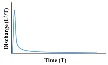
A spring hydrograph illustrates the temporal variations of the spring discharge reflecting the hydraulic processes in a karst aquifer [43]. Typically, a spring hydrograph is characterized by the peak discharge, the rising and the falling limbs, and two inflection points (Figure 2). The inflection points of the rising limb and the falling limb represent the maximum infiltration state [44] and the end of an infiltration event [43], respectively. The inflection point of the falling limb (i.e., the recession limb) is determined as the intersection of the early steep slope segment (i.e., flood recession) and the late smooth slope segment (i.e., baseflow recession).
Under various hydrological conditions, three flow regimes may influence the falling limb including (1) matrix restrained flow regime (MRFR), when conduit network is as fix-head boundary conditions, and the drainage process is controlled by the matrix alone, (2) conduit-influenced flow regime (CIFR), when the hydraulic gradient in the conduits is not negligible during the recession process and the recession process depends on the hydraulic parameters matrix and conduit network [37,45], and (3) conduit flow regime (CFR), when the hydraulic head in the conduit is greater than the hydraulic head in the matrix [16]. Generally, the flow regime in the karst aquifers is influenced by the point and diffuse recharge events and the contribution of the matrix and/or conduits through-flow system. In particular, the recession limb of the spring hydrograph constitutes a linear and non-linear form in response to large and small recharge events, respectively [46]. Bailly-Comte et al. [16] showed that a linear decrease in the karst spring’s discharge can be assigned to the conduit flow regime (CFR) characterized by the low permeability of the matrix and concentrated recharge to the karst conduit’s network. The slope of the recession curve in the conduit flow regime is denoted by β and can be calculated based on Equation (4) [16]:
QCFR (t) = Qmaxβ × t
where QCFR (t) is the discharge at time t ( L 3 T 1 ), Qmax is the maximum discharge ( L 3 T 1 ), and β ( L 3 T 2 ) is the linear decrease in the recession curve slope.
Considering concentrated recharge events, the inflection point of the falling limb has been introduced as an indication of the completion of the infiltration and recharge processes and the CFR [16,43]. However, considering diffuse recharge events, the conduit network constitutes fixed-head boundary conditions and flow conditions correspond to a matrix flow regime, with the inflection point of the falling limb only indicating the fulfillment of the recharge and infiltration processes. After completion of the recharge (i.e., beyond the inflection point of the falling limb), the baseflow exponentially decreases over time and can be calculated based on Equation (5) [47]:
Q(t) = Q0eαt
where Q0 and Q(t) are the discharges at the initial time and time t ( L 3 T 1 ), respectively, and α ( T 1 ) is the recession coefficient.
Since the baseflow of the recession curve (beyond the inflection point of the falling limb) is less influenced by the recharge events, it can be considered as representative of the general characteristics of karst aquifers. Therefore, the baseflow recession can be influenced by MRFR or CIFR [43,45].
Although the recession curve of a homogeneous matrix can be decomposed into several exponential components (α), these components should not be considered as discharge from different parts of the aquifer with different hydraulic conductivity due to the complexity of diffuse flow through the matrix [43]. Fiorillo [48] showed that the variation of the recession coefficient can be explained by the variation of the discharge area without any change in permeability of the material. High values of α can be associated by a small catchment area or by drainage of water-filled shafts.
Moreover, the direction of the exchange flow can temporally vary due to the establishment of the MRFR/CIFR or CFR conditions [16]. Although, the general direction of the exchange flow is from the matrix to conduits (i.e., the exponential slope of the recession curve), a high-pressure head in conduits is necessary to establish an exchange flow from conduits to the matrix (i.e., the linear slope of the recession curve). This high-pressure head in conduits has been simulated by increasing the concentrated recharge through conduits as suggested by Malenica et al. [38].
In addition to the direction of exchange flow, the different values of the exchange coefficient, as well as the amount of exchange flow, influence the characteristics of the hydrograph. The larger exchange coefficient allows for the easy transfer of a significant amount of water from conduits to the matrix in response to a significant rainfall event. Also, the slope of the recession curve reduces and the baseflow becomes more important when reversion of the exchange flow direction occurs from the matrix to the conduits during a baseflow period [5,18]. Therefore, the small exchange coefficients in comparison to the large exchange coefficients produce a larger peak discharge and a steeper slope of the recession segment under point recharge conditions [18,19]. The effect of the exchange flow on the discharge volume of the spring depends on the matrix hydraulic conductivity. The large matrix hydraulic conductivity allows the point recharged water to flow easily from the conduit toward the matrix. Accordingly, the quick-flow tends to decrease. In contrast, in karst aquifers with low matrix hydraulic conductivity, the quick-flow volume is affected by the characteristics of the conduits [16]. Peterson and Wicks [14] estimated that the volume of exchange flow in the Devil’s Icebox–Connor’s Cave System (central Missouri, USA) changed from 0.34 to 6.85 × 10⁻⁵ m3 if the matrix hydraulic conductivity decreased from 8.54 × 10⁻⁶ to 1 × 10⁻¹¹ m/s, respectively.
The transition from pressurized to free-surface flow or vice versa in the conduits caused the changes in spring discharge. Although the exchange flow rate from the conduit to the matrix increased as a result of a quick increase in the water pressure in the filled conduits than partly filled conduits during rainfall, the spring discharge is less affected by the exchange flow in conduits with the free-surface flow [20].

2.2. Methodology

We hypothesize that the matrix-conduit exchange flow rate depends on the lumped exchange coefficient and the hydraulic head difference between the matrix and the conduit (Equation (1)). This study attempted to evaluate the effects of these parameters on the rate and direction of the exchange flow in a karst system using a synthetic modeling approach with MODFLOW-2005 Conduit Flow Process (CFP) developed by Shoemaker et al. [35]. The CFP package [35] allows groundwater flow simulation in the matrix based on Darcy’s law and flow simulation in the conduit based on the linear and nonlinear flow regime developed by the U.S. Geological Survey, (USGS) [30].
The proposed methodology consists of (1) building a synthetic karst aquifer to simulate spring hydrographs for a physical realist range of values for the exchange coefficient, the matrix hydraulic conductivity, and the conduit diameter, and (2) assessing the effect of variations in the parameter of interest on the exchange flow in terms of rate and flow direction.
The characteristics of the spring hydrographs, including peak discharge, peak time, the slope of the recession limb, and volume of baseflow (the volume of spring discharge from inflection point to the end of simulation time) were calculated and interpreted based on the rate and direction of the exchange flow.
Three-dimensional laminar flow in the matrix is solved based on Equation (6) [35]:
X ( K x x   h X ) + y ( K y y   h y ) + z ( K z z   h z ) ± W = S s   ( h t )
where K x x , K y y , K z z   are the hydraulic conductivity values in the x, y, z directions, respectively (L T 1 ), h is the hydraulic head [L], W is the volumetric flux per unit volume ( T 1 ), Ss is the specific storage ( L 1 ), and t is time (T).
The conduit network within the matrix porous media is defined as pipes characterized by elevation, diameter, roughness, and exchange coefficient. The two ends of the pipes are connected to the nodes at the center of each matrix cell [35]. Depending on the Reynolds number, the flow in the pipes can be either turbulent or laminar flow.
Both laminar and turbulent pipe flow can be approximated with the Hagen-Poiseuille (Equation (7)) and the Darcy-Weisbach equations (Equation (8)), respectively [35]:
Q = π d 4 ρ g Δ h 128 μ Δ l τ   or   Q = A   ρ g d 2 Δ h 32 μ Δ l τ
where d   is the pipe diameter (L), Δ h Δ l is the hydraulic head gradient along the pipe (unitless), ρ is the density of the water (ML−3), μ is the viscosity of the water (M L 1 T 1 ), g is the gravitational acceleration constant (L T 2 ), and τ is tortuosity (unitless).
Q = A   2 Δ h d g f Δ l
where Q is the volumetric flow rate ( L 3 T 1 ), Δh is the hydraulic head losses along the pipe (L), A is the cross-sectional area perpendicular to flow ( L 2 ), f is the friction factor (unitless) and is quantified based on the empirical Colebrook-White formula [49,50] in CFPM1.
1 f   = 2 log [       k c       3.71 d + 2.51 R e f ]
where k c (L) represents the mean roughness height of the conduit wall micro-topography. R e is Reynolds number (unitless) and d is the pipe diameter (L).
Using the CFPM1 package, the equation to estimate discharge in the conduit is solved independently of the matrix equation [35]. However, the relationship between the matrix and the pipe network is shown by the influence of exchange flow as an inflow or outflow component in the water balance as well as the distribution of the hydraulic head in each of the matrix and pipe networks. For any pipe nodes, conservation volumetric flow is calculated according to Kirchhoff’s law (Equation (10)).
i = 1 n p Q i p Q e x + Q R   ± Q s = 0
where Q i p , Q e x , Q R , and Q s represent pipe flows, exchange flow, direct recharge, and changes in storage, respectively [35].
Briefly, the volumetric exchanges ( Q e x ) are defined as the total volumetric exchange Q t e x ( L 3 T 1 ) as follows:
Q t e x = i n = 1 m x n o d e i p = 1 n p Q e x  
where i n is an integer subscript for each node, m x n o d e is the maximum number of nodes in the model, i p is an integer subscript for each pipe that connects to node i n , n p is the number of pipes connected to node i n . Individual volumetric exchanges ( Q e x ) are computed using the Darcy formulation assuming that exchange flow is not turbulent.
Q e x = α e x ( j , i , k )   ( h i n h j , i , k )
where α e x ( j , i , k )   is the exchange coefficient ( L 2 T 1 ), h i n is the head (L) at node i n computed by the CFP, h j , i , k is the head (L) in the encompassing matrix cell [35]. The exchange coefficient can be determined by two options in CFP. The first option allows the user to assign the exchange coefficient for each node in the pipe network. The second option estimates the exchange coefficient using pipe geometry and conduit wall permeability (Equation (13)).
α e x ( j , i , k ) = i p = 1 n p K j , i , k   π d i p   1 / 2 ( Δ l i p τ i p )   r i p
where K j , i , k is the conduit wall permeability term (L T 1 ) in the matrix cell j,i,k, π is the mathematical constant pi (unitless),   d i p is the diameter (L) of pipe i p connected to node i n , Δ l i p is the straight-line length between nodes (L) of pipe i p connected to node i n , τ i p is the tortuosity (unitless) of pipe i p connected to node i n , r i p is the radius of the pipe (L). Therefore, α e x is a lumped geometrical and hydraulic property (diameter of the conduit, tortuosity, and the conduit wall permeability) of the karst system [19].

3. The Conceptual Model and Scenarios

3.1. The Geometry of the Conceptual Model

To examine the effect of the exchange flow on the spring hydrograph, a synthetic karst aquifer is proposed. The dimensions and geometry of the synthetic model are analogous to the characteristics of hypothetical models used in previous research [15,19,20,37].
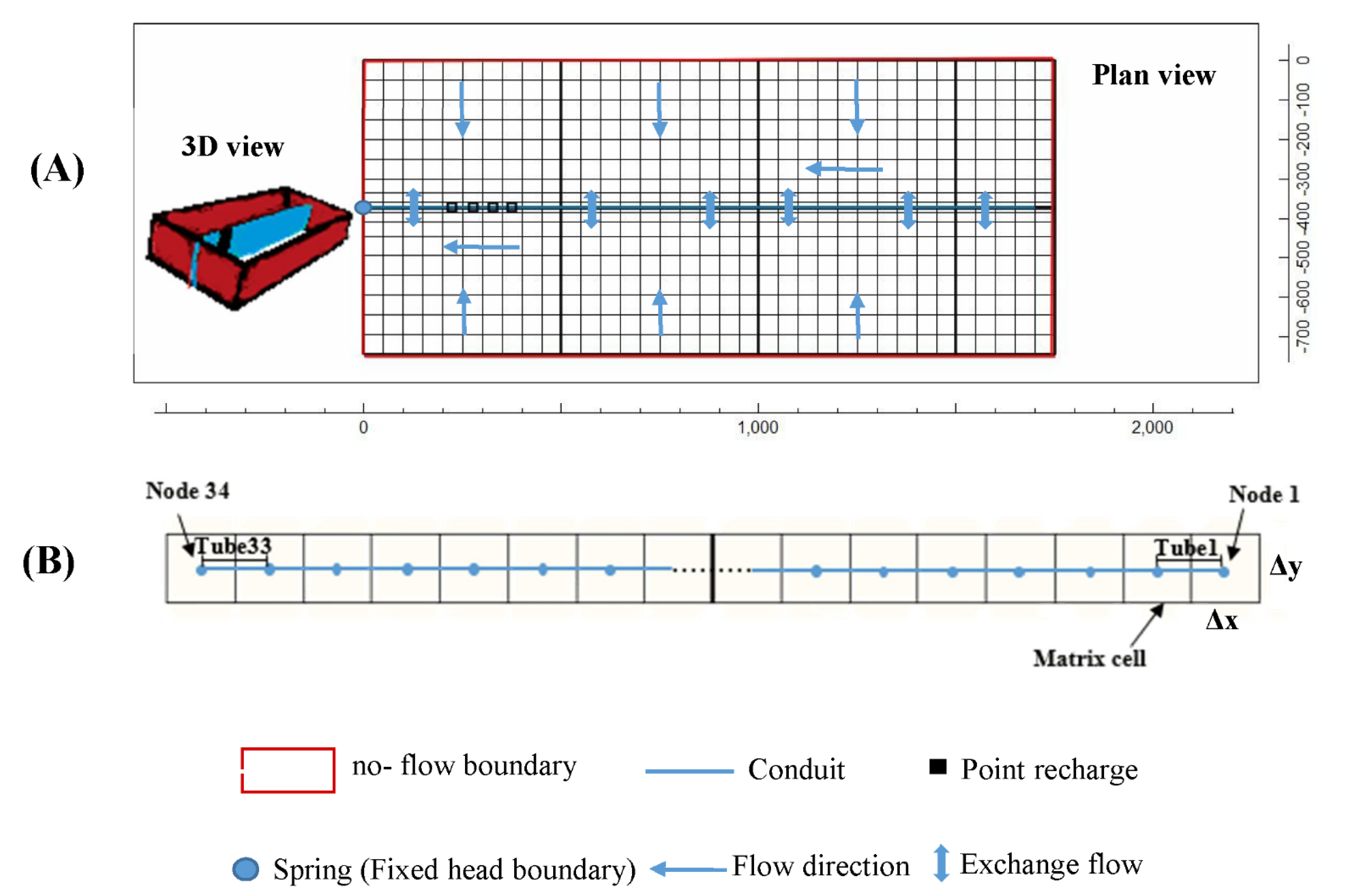
The synthetic model consists of a single conduit with a length of 1700 m which is located in a two-dimensional matrix with a length and width of 1750 and 745 m, respectively (Figure 3). The model domain is divided into 665 cells. The width of both the columns Δx and the rows Δy was set to 50 m except for seven rows adjacent to the conduit where the width of rows decreases from 50 to 35, 25, 10, and 5 m, respectively (Figure 3).
The aquifer is considered to be an unconfined layer with a thickness of 100 m. A value of 5 × 10⁻³ is assigned to the specific yield. The bottom of the aquifer is considered to be at zero elevation. An initial value of 1 × 10⁻⁵ m/s is assigned to the hydraulic conductivity.
Neumann type (no flow) boundary is defined for the boundaries of the model. The karst conduit is located in the middle of the matrix (10th row) with an elevation of 10 m and discretized in 33 successive pipes with a length of 50 m. A fixed head of 20 m is defined in node 34 at the end of the conduit as the discharge point of the model (Figure 3).
The general flow direction is from the right to the left of the model. The karst conduit is saturated and under pressure in all time steps. The initial hydraulic head is set to 20 m and the water temperature is set at 20 . The total simulation period of the model is 50,000 min and each step is set to 5 min [37]. The model is initiated in a steady-state at time step 1 (i.e., t = 0).

3.2. Types of Recharge

Net recharge (diffuse or concentrated) is considered only from the top of the aquifer. The diffuse recharge is only assigned to the matrix cells. The Gaussian formula is used to generate rainfall events with an interval of 5 min as follows:
f ( t ) = b 2 π δ 2 e ( t m a ) 2 2 δ 2
where f ( t ) is the cumulative rainfall at each time step ( t ) (mm), m ,   δ 2 , a , and b are the constants of 90, 1.5, 20, and 0.12, respectively [37]. m is determinative of the location of the center of the peak, δ 2 together with a determine the extent of kurtosis or flattening, and b is the intensity of rainfall. The rainfall period is assumed from 35 to 210 min from the initial time of the model run.

3.3. Discharge Point of the Synthetic Model

Spring is generally considered as the discharge point of the conceptual model. In the designed synthetic model, the spring is directly supplied by the conduit [37,51]. If the spring discharge is mainly supplied by the point recharge (i.e., quick-flow) and the recession curve follows a linear slope (β), the flow regime is dominantly the CFR. However, the flow regime corresponds to the CIFR and/or the MRFR when the spring discharge is mainly supported by the exchange flow from the matrix to the conduit (as the baseflow), consequently, the recession curve follows an exponential slope (α).

3.4. Definition of the Scenarios

The direction of the exchange flow between the matrix and the conduit depends on the direction of the hydraulic head difference between the matrix and conduit. Two sets of scenarios including group A, where QMC+ discharge (the direction of the exchange flow from the matrix to the conduit) was established during all time steps, and group B, where QMC− discharge (the direction of the exchange flow from the conduit to the matrix) is in early time steps during a rainfall event and QMC+ discharge is in the next time steps. The characteristics of the scenarios are presented in Table 1.
The first (i.e., A1 and B1), second (i.e., A2 and B2), and third (i.e., A3 and B3) scenarios were designed to examine the effect of the exchange coefficient, the conduit diameter, and the matrix hydraulic conductivity on the shape of the spring hydrograph, respectively.
Although the different values of 10−2, 10−3, 10−4, and 10−5 m2/s have been assigned to the exchange coefficient in the A1 and B1 scenarios, the conduit diameter and the matrix hydraulic conductivity remained constant with a value of 0.5 m and 10−5 m/s, respectively. Moreover, scenarios A2 and B2 were executed by assigning the different conduit diameters (0.1, 0.2, 0.3, 0.4, 0.5 m). The matrix hydraulic conductivity was assumed to be variable (10−3, 10−4, 10−5, 10−6 m/s) in the third scenarios A3 and B3. In the second and third scenarios, the exchange coefficient was assumed to be constant as 10−3 m2/s.
Based on the direction of exchange flow in scenarios, the flow regime is divided into two groups including (1) CFR, where the direction of exchange flow is from the conduit to the matrix during a restricted part of CFR and it is reversed for the rest of the time and (2) CIFR and/or the MRFR, where the direction of exchange flow is from the matrix to the conduit.
The CRCH Package in CFP is used to define the point recharge (i.e., concentrated recharge) in the two sets of scenarios. The point recharge in nodes 27, 28, 29, and 30, (Figure 3) is equal to the rate of the matrix diffuse recharge in one set (Set A in Table 1) while it is 500 times larger in another set of scenarios (Set B in Table 1).

4. Results and Discussion

4.1. The Effect of the Exchange Coefficient on the Karst Spring Hydrograph

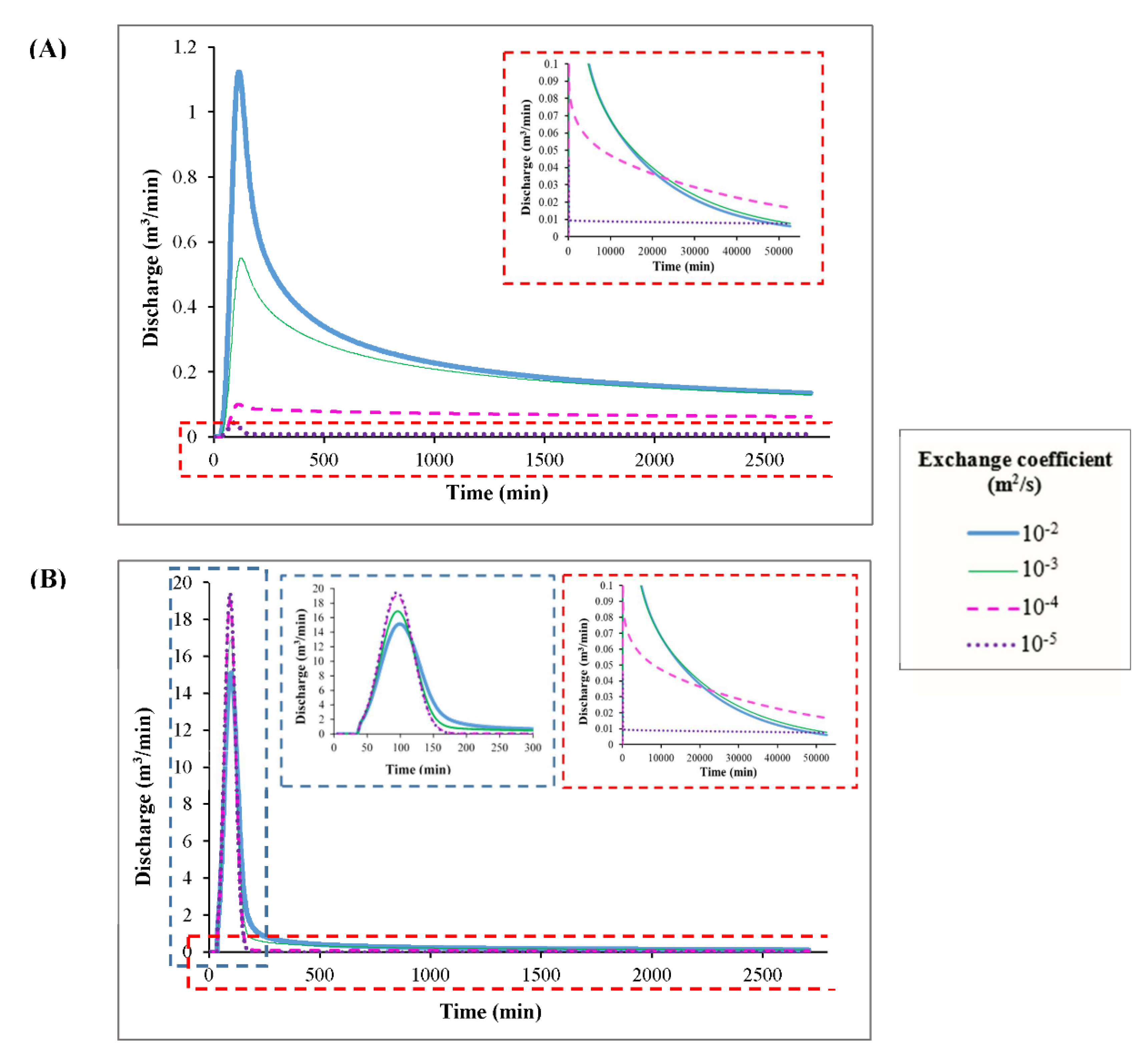
The results of scenarios A1 and B1 are presented in Figure 4, Supplementary Tables S2 and S3, respectively. Considering scenario A1, the flow regime is mainly controlled by the CIFR and/or the MRFR, as well as by the direction of the exchange flow being from the matrix to the conduit (QMC+ discharge). Accordingly, the hydrograph recession curve follows an exponential slope (Figure 4A). However, assuming exchange coefficient value of 10−5 m2/s, the rate of QMC+ discharge becomes less than the point recharge (Supplementary Table S2). Therefore, the CFR is established during the earlier time of the recession curve until 130 min. As a result, the slope of the recession curve follows the linear and exponential slopes (both show QMC+ discharge) for the 90 to 130 min period and 130 min to the end of the simulation time, respectively (Figure 4A and Supplementary Table S2). As the exchange coefficient increases, the recession curve illustrates segments with steeper slopes (α) as well as a wider range of variations. For example, due to the assigning of 10−2 m2/s to the exchange coefficient, four segments with α of 6.9 × 10⁻³, 1.3 × 10⁻³, 3.0 × 10⁻⁴, and 5.6 × 10⁻⁵ min−1 were distinguished. However, considering lower values for the exchange coefficient such as 10−5 m2/s, two segments with α values of 7.1 × 10⁻³ and 3.6 × 10⁻⁶ min−1 were extracted (Figure 4A). The results revealed that the decrease in the exchange coefficient from 10−2 to 10−5 m2/s caused the decrease in the volume of QMC+ discharge (i.e., the baseflow volume) for the same period from the second inflection point to 50,000 min from 2299.20 to 436.08 m3 as well as Qp from 1.12 to 0.044 m3/min.
Considering scenario B1, the exchange flow from the conduit to the matrix (QMC− discharge) was only established in part of the CFR time during rainfall in the karst aquifer (Figure 4B and Supplementary Table S3). The duration of the period corresponds to the time interval where QMC− discharge depends on the exchange coefficient. Water flux intensity from the conduit to the matrix decreased with the decrease in the exchange coefficient. Moreover, the hydraulic head in the matrix and the conduit are not rapidly balanced with the decrease in the exchange flow. Therefore, the duration of QMC− discharge becomes longer under CFR conditions. When the exchange coefficient decreased from 10−2 to 10−5 m2/s, the value of the linear slope of β increased from 0.23 to 0.32 m3/min2, and the peak discharge increased from 15.14 to 19.49 m3/min. However, following scenario A1, the discharge volume of the baseflow for the same period decreased from 2431.00 to 450.34 m3 and also the number of sub-segments with different slopes, or in other words, the variation range of α (slope of recession curve in the baseflow segment), decreased. In general, the range of variation of α in scenario B1 is higher than the range of variation observed considering scenario A1. In scenario B1, the slope of α was computed to be 2.4 × 10⁻², 3.9 × 10⁻³, 1.1 × 10⁻³, 3.3 × 10⁻⁴, and 5.6 × 10⁻⁵ min−1 by assuming exchange coefficient value of 10−2 m2/s (Figure 4B) as well as 2.3 × 10⁻² and 3.6 × 10⁻⁶ min−1 for exchange coefficient value of 10−5 m2/s (Figure 4B). Considering both A1 and B1 scenarios, there is no evidence to support that peak time depends on the exchange coefficient.
Since the water level in the conduits increases due to the heavy point recharge of conduits, QMC− discharge can potentially increase in the early time of the recession curve. The contribution of QMC− discharge in the recession curve is evidenced by the CFR and the linear slope in the recession curve. The results revealed that QMC− discharge is not a long-term process and the direction of exchange flow is reversed in response to the decreasing of the water level in the conduit, although, the flow regime remains as the CFR. After completion of the CFR, the flow is controlled by the CIFR and/or the MRFR and the recession curve follows an exponential slope. Figure 5 is an example of QMC− discharge that contributes only in the early time of the recession curve in the spring hydrograph assuming the exchange coefficient of 10−3 m2/s. The short-term effect of other phenomena on the spring hydrograph resulting from a temporary increase in the water level in the conduit is investigated by Chang et al. [37]. They showed the turbulent conduit could also strongly influence the early time of the spring hydrograph from the point recharge and may also disappear at the late time of the spring hydrograph.
Based on the results of scenarios A1 and B1, when one observes the occurrence of a QMC− discharge event during a restricted part of the recession curve, the peak discharge increases when the exchange coefficient decreases. However, the volume of baseflow (from the second inflection point to 50,000 min) decreased. This function can be explained by the fact that during the flow condition where QMC− discharge occurs, a part of the point recharge is transferred to the matrix. This volume of water is drained back to the conduit when the exchange flow goes from the matrix to the conduit (QMC+ discharge). Therefore, with the decrease in the exchange coefficient, the intensity of QMC− discharge decreases, and most of the conduit flow is transferred to the spring as quick-flow.
In contrast, when the flow condition is dominated by the QMC+ discharge over the whole recession curve, the spring discharge is supplied by the mixture of the QMC+ discharge and the point recharge to the conduits. Therefore, spring discharge increases as the exchange coefficients increase. Due to the extra recharge of the matrix under the condition of the QMC− discharge, the volume of the baseflow in scenario B1 is larger than that in scenario A1 where the QMC+ discharge is preponderant over the whole recession curve.

4.2. The Influence of the Conduit Diameter on the Karst Spring Hydrograph

The results of scenarios A2 and B2 (constant value of 10−3 m2/s for the exchange coefficient and assigning different values of 0.1, 0.2, 0.3, 0.4, 0.5 m to the conduit diameter) are briefly presented in Supplementary Tables S4 and S5.
The results of scenario A2 (i.e., the CIFR and/or the MRFR and QMC+ discharge) revealed that the decrease in the conduit diameter value from 0.5 to 0.1 m caused a decrease in the peak discharge from 0.55 to 0.098 m3/min. However, for the same period from the second inflection point to 50,000 min, the baseflow volume increased from 2312.65 to 2325.97 m3 as the conduit diameter decreased from 0.5 to 0.2 m (Figure 6A and Supplementary Table S4). Also, these results are observed in the study by Chang et al. [37] in the karst aquifer influenced by the diffuse recharge. Moreover, α also decreased in response to conduit diameter decrease. However, with the change in the conduit diameter from 0.5 to 0.1 m, the time of peak discharge remains constant.
The results showed both QMC− discharge (only in the early time of the recession segment) and QMC+ discharge established in the scenario B2 (Figure 6B and Supplementary Table S5). Based on the results, when the conduit diameter decreased from 0.5 to 0.1 m, the peak discharge decreased from 16.90 to 0.62 m3/min. However, for the same period from the second inflection point to 50,000 min, the baseflow increased from 2411.30 to 2813.99 m3 as the conduit diameter decreased from 0.5 to 0.1 m.
The duration of the occurrence of QMC− discharge became longer for the smaller conduit diameters so that for a conduit diameter of 0.1 m, QMC− discharge was dominant for the entire time of the CFR. When conduit diameter decreased from 0.5 to 0.1 m, the slope of the recession curve in the CFR (β) decreased from 0.29 to 0.003 m3/min2 and α also decreased in response to a conduit diameter decrease. The time of the peak discharge increased from 95 to 105 min for the conduit diameters of 0.5 and 0.1 m, respectively.
A smaller conduit diameter can create a larger volume of baseflow. This is due to the larger exchange flow as a result of the more important difference of the hydraulic head between the matrix and conduit (Equation (1)). Also, due to the extra recharge of the matrix under the condition of the QMC− discharge, the volume of the baseflow in scenario B2 is larger than that in scenario A2 where the QMC+ discharge is preponderant over the whole recession curve.

4.3. The Influence of the Matrix Hydraulic Conductivity on the Karst Spring Hydrograph

The scenarios A3 and B3 consisted of a set of cases with a constant value of the exchange coefficient (10−3 m2/s) and conduit diameter (0.5 m), and different values of the matrix hydraulic conductivity (10−3, 10−4, 10−5, 10−6 m/s).
The results of scenario A3 are presented in Figure 7A and Supplementary Table S6. Based on the results, when the matrix hydraulic conductivity decreased from 10−3 to 10−6 m/s, the peak discharge, the volume of baseflow for the same period from the second inflection point to 50,000 min and the peak discharge time changed from 0.87 to 0.33 m3/min, from 2424.35 to 940.250 m3, and from 150 to 110 min, respectively. Also, the number of non-linear segments with different slopes of the recession curve increased if a smaller value was assigned to the matrix hydraulic conductivity. As an example, a single α value of 3.5 × 10⁻⁴ and four α values of 7.7 × 10⁻³, 1.3 × 10⁻³, 2.8 × 10⁻⁴, and 1.3 × 10⁻⁵ min−1 were computed by assigning 10−3 and 10−6 m/s to the matrix hydraulic conductivity, respectively.
The results of scenario B3 (including both flow conditions: QMC− and QMC+) are presented in Figure 7B and Supplementary Table S7. The QMC− discharge was only established in the early time of the CFR (i.e., the beginning segments of the recession curve). Based on the results, when the matrix hydraulic conductivity decreased from 10−3 to 10−6 m/s, the duration of occurrence of QMC− discharge was estimated shorter, the peak discharge increased from 16.27 to 17.54 m3/min, and β increased from 0.27 to 0.29 m3/min2. However, the volume of baseflow for the same period from the second inflection point to 50,000 min decreased from 2600.20 to 980.55 m3. The rate of the exponential slope (α) in the segments with the CIFR and/or the MRFR increased in response to assigning a smaller value to matrix hydraulic conductivity. For example, the exponential slope (α) values of 2.6 × 10⁻², 4.8 × 10⁻⁴, and 3.5 × 10⁻⁴ min−1 and 5.3 × 10⁻², 3.9 × 10⁻³, 1.2 × 10⁻³, 2.8 × 10⁻⁴, and 1.2 × 10⁻⁵ min−1 were estimated when the matrix hydraulic conductivity considered to be 10−3 and 10−6 m/s, respectively. In scenario B3, the time of the peak discharge time remained constant when the matrix hydraulic conductivity changed.
Based on the results of scenarios A3 and B3, the movement of the water entering the matrix due to QMC− discharge is slow if the small values are assigned to the matrix hydraulic conductivity. As a result, the water head is locally increased in short distances around the conduit. Under such a condition (i.e., assigning a small value to the matrix hydraulic conductivity), the larger volume of the point recharge to the conduit is quickly transferred to the spring and causes the volume of the quick flow and β to increase. On the other hand, the volume of the baseflow decreases for the same period from the second inflection point to 50,000 min.

4.4. Generalization of the Effect of Exchange Flow on the Spring Hydrograph

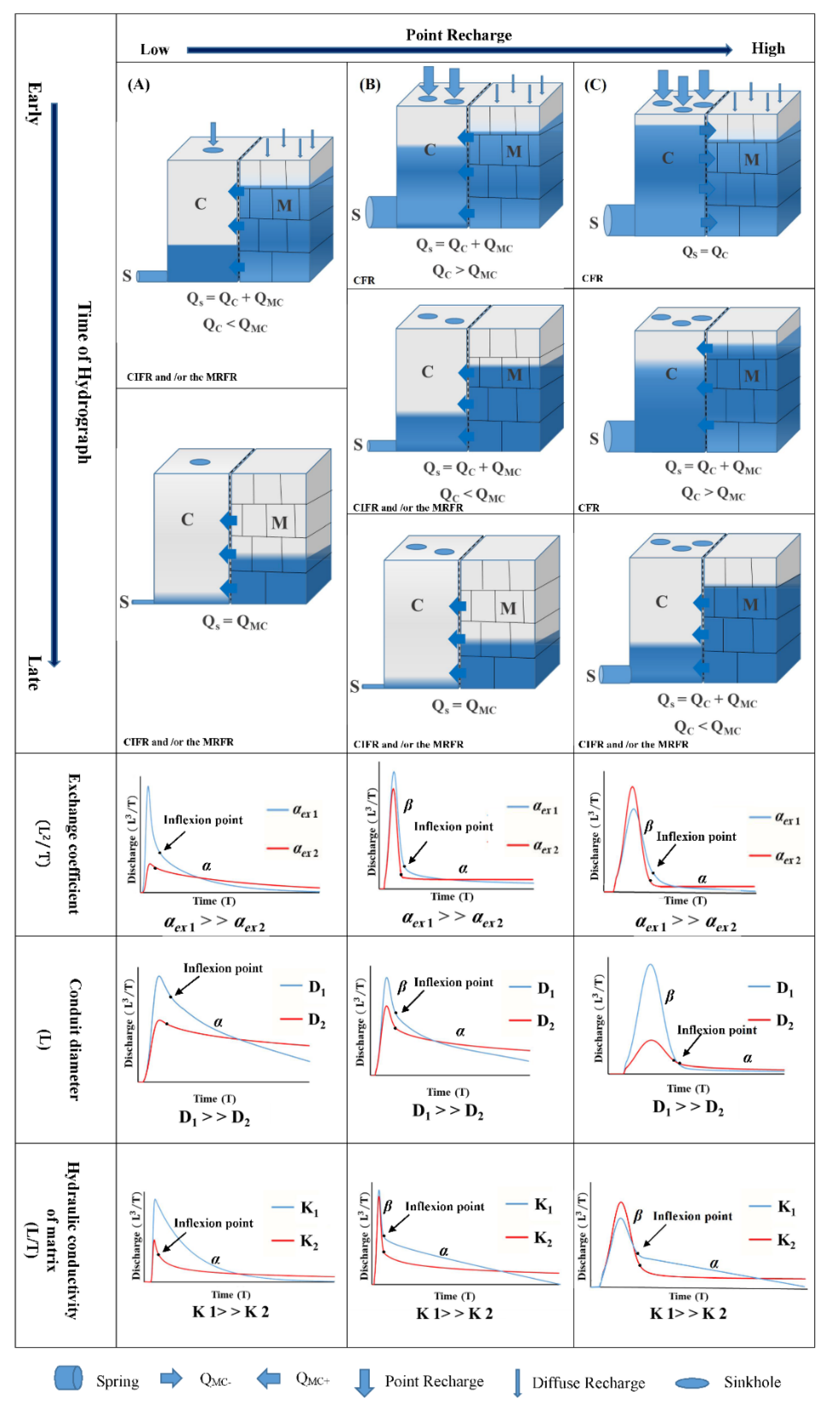
The results of the scenarios (Section 4) are used to develop a conceptual model of the behavior of the exchange flow in the karst spring hydrograph (Figure 8). To explain the systematic variation of the spring hydrograph in response to the variation of the exchange flow, two types of recharge are assumed in Figure 8: the diffuse and point recharge that infiltrates slowly and quickly into the matrix and the conduit, respectively. The difference in type and rate of the recharge causes QMC and/or QMC+ discharge due to the difference in the hydraulic head between the matrix and conduit. The change of QMC+ to QMC discharge is influenced by the flow regime (i.e., CIFR and/or the MRFR and CFR) and the rate of point recharge. In this conceptual model (Figure 8), the rate of point recharge changes from low to high while the diffuse recharge is assumed to be at a constant rate. Moreover, the recharge event takes place during the early time and the spring discharge starts to increase in response to the recharge event.
Based on the history of recharge and exchange flow, it can be expected that the different values of exchange coefficient, conduit diameter, and matrix hydraulic conductivity play different roles in creating hydrographs with different characteristics such as peak discharge and baseflow volume (Figure 8). In this comparison, with the change of each of the parameters of interest (exchange coefficient, conduit diameter, and matrix hydraulic conductivity), other parameters of the karst aquifer are assumed constant.
In column A, there is no CFR due to small amounts of point recharge in the karst aquifer. Under such conditions, the spring hydrograph is influenced by CIFR and/or the MRFR and the direction of the exchange flow is from the matrix to the conduit (QMC+ discharge). In the CIFR and/or the MRFR, the recession curve follows an exponential (α) equation. Under these conditions, the simulated hydrographs present greater peak discharge assigning a large value to each of the parameters of interest (the exchange coefficient, the conduit diameter, and the hydraulic conductivity of the matrix). The number of segments of the recession curve with different slopes increase when the exchange coefficient is large. However, they decrease when the hydraulic conductivity of the matrix is large.
Also, the inflection point in the recession curve indicates the end of the infiltration and recharge process. In column B, although the CFR can be established in the early time steps of hydrograph by increasing the amount of point recharge, exchange flow direction may still be from the matrix to the conduit (QMC+ discharge). In the CFR, the recession curve follows a linear relationship with the β-slope. Under these conditions, the inflection point in the recession curve indicates the end of the CFR as well as the end of the infiltration and recharge processes. Similar to column A, under these conditions, the higher values of each of the parameters of interest (the exchange coefficient, the conduit diameter, and the hydraulic conductivity of the matrix) make the larger peak discharge. Finally, in column C, the direction of the exchange flow changes from the conduit to the matrix (QMC discharge) when the point recharge increases significantly. In this case, the spring hydrograph experiences three modes including (1) CFR and QMC− discharge in the early times of the hydrograph, (2) the CFR and QMC+ discharge, and (3) the CIFR and/or the MRFR and QMC+ discharge in the rest of the time. In modes of 1 and 2, the recession curve follows a linear relationship with the β-slope, and in the mode of 3, the recession curve follows an exponential relationship with the α-slope. Then, the QMC discharge and conduit flow regime consist of short-term processes. Over time, the flow regime changes to CIFR and/or the MRFR, as well as the exchange flow direction, which changes from the matrix to the conduit because the drop of the hydraulic head in the conduit is faster than that in the matrix. Under the conditions indicated in column C, where the karst system experiences QMC discharge in the part of CFR due to a large point recharge, the response of the spring hydrograph to the exchange coefficient, the conduit diameter, and the hydraulic conductivity of the matrix is different from that in columns A and B. Therefore, the simulated hydrographs present greater peak discharge when the exchange coefficient is small. As a result, the small volume of water is stored in the matrix due to the exchange flow and the majority of water enters into a conduit network that is drained by the spring. Moreover, under the condition that constitutes QMC discharge (column C), the volume of baseflow will be larger than the condition when the karst system has only experienced QMC+ discharge (columns A and B) for a specific exchange coefficient. This phenomenon is evidenced by a flow pipe as spring outflow volume (the higher the volume of the discharge caused by the larger value of the pipe diameter). Based on the results of a conceptual modeling approach, the influence of matrix hydraulic conductivity on the spring hydrograph is the same as the role of the exchange coefficient in different flow regimes and directions of exchange flow. However, regardless of the exchange flow direction (from the matrix to the conduit or conversely) that occurs in the karst aquifer, larger conduit diameters produce hydrographs with larger discharge peaks. However, a smaller conduit diameter can create a larger volume of baseflow. This is due to the larger exchange flow as a result of the more important difference in the hydraulic head between the matrix and conduit.
To classify spring hydrographs and conclude for possible internal characteristics of a karst aquifer, a systematic approach is proposed based on the reliable concluding points obtained from the analysis of the shape of the synthetic spring hydrographs that resulted from scenarios A and B (Table 2). Based on the defined scenarios, the amount of the conduit flow in scenario B is more important than that in scenario A, although, the rate of recharge into the matrix is the same in both scenarios. The matrix properties such as the specific yield and the aquifer thickness are constant in both scenarios for the aquifer with the no-flow boundaries where the outflow of the matrix is through the exchange flow from the matrix to the conduit and then spring.
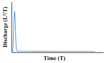
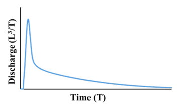
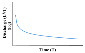
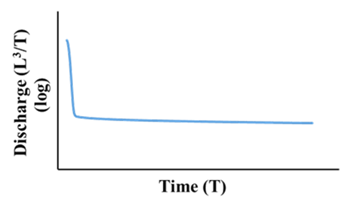
Given a spring hydrograph, following the proposed approach in Table 2 helps to assess preliminary knowledge about the exchange flow as well as the internal karst structure. Firstly, the logarithmic recession curve should be derived based on the original spring hydrograph (Table 2). The visual and clear existence or lack of inflection point on the recession curve is a decision point. If the inflection point is visually clear, its position should be identified. Under this condition, 3 modes can be imagined.
In mode I, the inflection point is located before an arc region. This condition is observed in scenarios A and B by assigning large values to the exchange coefficient and small values to the transmissivity of the matrix.
In modes I and III, the inflection point is located before a non-arc region that represents a rapid transition from the flood recession to the baseflow recession. Mode II is observed in scenarios A and B by assigning small values to the exchange coefficient and different large and small values to the transmissivity of the matrix. Under these conditions, the conduit flow is more important than that in mode I.
The inflection point is not distinguishable in model IV (Table 2). By assigning large values to the exchange coefficient and the transmissivity of the matrix, the obtained hydrographs were similar to mode III in the scenario B and mode IV in scenario A and the inflection point on the logarithmic curve of the recession was not observed (Table 2). A real field example of this condition is found in the Santa Fe River Rise, studied by Bailly-Comte et al. [16].
Based on the result of the modeling for the synthetic karst aquifer, when the exchange coefficient is large enough, the slope of the recession curve under the condition of the baseflow is higher than when the exchange coefficient is small (the modes of I, III, and IV). Also, by assigning small values to the exchange coefficient (mode II), the difference of the hydraulic head between the conduit and the matrix is more important than when large values are assigned to the exchange coefficient.
Despite extensive attempts in this research including the running of a lot of simulations under the different characteristics of the synthetic karst aquifer such as the matrix with different dimensions, saturation thickness, different rate of recharge, and effective porosity, it is unlikely to introduce a global value for the large/small values of the exchange coefficient and the difference of the hydraulic head between the conduit and the matrix in karst aquifers. It seems that the large/small values of the exchange flow depend on the conditions of each karst aquifer. Therefore, a definite value cannot be proposed as the large/small values for all aquifers. This topic requires more detailed research and can be suggested as an open question for further research.

5. Conclusions

The main focus of the study was to investigate the effect of the matrix–conduit exchange flow (amount and direction) on the karst spring hydrograph. Assuming different values of the exchange coefficient and the hydraulic head difference between the matrix and the conduit allow for the investigation of the effect of matrix–conduit exchange flow magnitude on a spring hydrograph. The difference of hydraulic head between the matrix and the conduit influences the direction of exchange that in turn depends on the amount and type of recharge (point recharge or diffuse recharge). In most cases, fluxes go from the matrix to the conduit. Increasing the point recharge leads to a gradient inversion between matrix and conduit, as well as the directions of the exchange flow. After a rainfall event, the water entering the matrix under a short-term process of the QMC discharge returns to the conduit as baseflow. Under this condition, depending on the gradient and the magnitude of the exchange flow, the volume of baseflow increases and becomes greater than the scenario where there is only QMC+ discharge during recharge and recession events (as seen in scenario A). The shape of the spring hydrograph can be influenced by the direction of the exchange flow during the recharge and recession events. Hence, if the direction of exchange flow is from the conduit to the matrix, even during a restricted part of the conduit flow regime, the simulated hydrographs present greater peak discharge when each of the parameters of interest (the exchange coefficient or the hydraulic conductivity of the matrix) are small.
According to the different scenarios, it appears that the amount of exchange flow may strongly influence the spring discharge of the karst aquifers accordingly in the karst system conceptualization. However, there is a challenge to estimate the matrix–conduit interaction since it is difficult and quite impossible to quantify in the field.
Assessing the matrix–conduit dynamics can be used for a wide range of applications in real karst systems. The following issues can be investigated concerning the matrix–conduit dynamics:
Is aquifer vulnerability to contaminants influenced by matrix–conduit dynamics based on both the short-term and long-term?
Can a punctual infiltration of contaminant deteriorate the capacitive function of an aquifer?
May the groundwater abstraction influence the dynamics of the quick and slow flow? Hence, deteriorating the local water resource? In particular, in the coastal aquifers under pumping, it can be one of the major environmental concerns. Geng and Michael [52] and Kreyns et al. [53] showed the importance of conduits and preferential flow paths on the complexity of the saltwater intrusion distribution pattern and mixing dynamics between saline and fresh groundwater.
This can also lead to better constrain the karst structure (i.e., conduit geometry). This kind of research may also be considered together with solute transport modeling. Therefore, the correct estimation of the exchange flow (amount and direction) is of prior importance when dealing with the above-mentioned issues in a real case study.

Supplementary Materials

The following are available online at https://www.mdpi.com/article/10.3390/w13091189/s1: Table S1. Reviews of list of introduced formulas for computing the exchange flow. Table S2. The characteristics of the spring hydrograph in the scenario A1. Table S3. The characteristics of the spring hydrograph in scenario B1. Table S4. The characteristics of spring hydrograph in response to changes of conduit diameter in scenario A2. Table S5. The characteristics of spring hydrograph in response to changes in conduit diameter in scenario B2. Table S6. The spring hydrograph changes influenced by matrix hydraulic conductivity changes in scenario A3. Table S7. The spring hydrograph changes influenced by matrix hydraulic conductivity changes in scenario B3.

Author Contributions

Conceptualization, M.S. and Z.M.; methodology, M.S. and V.S.; software, M.S.; validation, Z.M., V.S. and D.L.; formal analysis, M.S.; investigation, M.S.; resources, Z.M.; data curation, M.S.; writing—original draft preparation, M.S.; writing—review and editing, Z.M., V.S. and D.L.; visualization, M.S.; supervision, Z.M.; project administration, Z.M.; funding acquisition, Z.M., V.S. and D.L. All authors have read and agreed to the published version of the manuscript.

Funding

This research received no external funding.

Institutional Review Board Statement

Not applicable.

Informed Consent Statement

Not applicable.

Data Availability Statement

Not applicable.

Acknowledgments

The authors gratefully thank the associate editor and three anonymous reviewers for their constructive comments and suggestions which made major improvements to the manuscript through several rounds of review. The first and second authors would thank the Shiraz University for permanent support during this research.

Conflicts of Interest

The authors declare no conflict of interest.

References

  1. Goldscheider, N.; Drew, D. Methods in Karst Hydrogeology; Taylor & Francis: London, UK, 2007; 264p. [Google Scholar]
  2. Oehlmann, S.; Geyer, T.; Licha, T.; Birk, S. Influence of aquifer heterogeneity on karst hydraulics and catchment delineation employing distributive modeling approaches. Hydrol. Earth Syst. Sci. 2013, 17, 4729–4742. [Google Scholar] [CrossRef] [Green Version]
  3. Hartmann, A.; Goldscheider, N.; Wagener, T.; Lange, J.; Weiler, M. Karst water resources in a changing world: Review of hydrological modeling approaches. Rev. Geophys. 2014, 52, 218–242. [Google Scholar] [CrossRef]
  4. White, W.B. Conceptual models for karstic aquifers. Speleogenesis 2003, 1, 1–6. [Google Scholar]
  5. De Rooij, R. Toward improved Numerical Modeling of Karst aquIFERS: COUPLING Trubulent Conduit Flow and Laminar Matrix Flow under Variably Saturated Conditions. Ph.D. Thesis, University of Neuchâtel, Neuchâtel, Switzerland, 2008. [Google Scholar]
  6. Berglund, J.L. Karst Aquifer Recharge and Conduit Flow Dynamics from High-Resolution Monitoring and Transport Modeling in Central Pennsylvania Springs. Ph.D. Thesis, Temple University, Philadelphia, PA, USA, 2019. [Google Scholar]
  7. Barenblatt, G.; Zheltov, I.; Kochina, I. Basic concepts in the theory of seepage of homogeneous liquids in fissured rocks [strata]. J. Appl. Math. Mech. 1960, 24, 1286–1303. [Google Scholar] [CrossRef]
  8. Warren, J.; Root, P. The Behavior of Naturally Fractured Reservoirs. Soc. Pet. Eng. J. 1963, 3, 245–255. [Google Scholar] [CrossRef] [Green Version]
  9. Narasimhan, T.N. Multidimensional numerical simulation of fluid flow in fractured porous media. Water Resour. Res. 1982, 18, 1235–1247. [Google Scholar] [CrossRef] [Green Version]
  10. Wang, X. On the coupled continuum pipe flow model (CCPF) for flows in karst aquifer. Discret. Contin. Dyn. Syst. B 2010, 13, 489–501. [Google Scholar] [CrossRef]
  11. Kazemi, H.; Seth, M.S.; Thomas, G.W. The interpretation of interference tests in naturally fractured reservoirs with uniform fracture distribution. Trans. Soc. Pet. Eng. 1969, 9, 463–472. [Google Scholar] [CrossRef]
  12. Moench, A.F. Double-Porosity Models for a Fissured Groundwater Reservoir With Fracture Skin. Water Resour. Res. 1984, 20, 831–846. [Google Scholar] [CrossRef]
  13. Chen, N.; Gunzburger, M.; Hu, B.; Wang, X.; Woodruff, C. Calibrating the exchange coefficient in the modified coupled continuum pipe-flow model for flows in karst aquifers. J. Hydrol. 2012, 414-415, 294–301. [Google Scholar] [CrossRef]
  14. Peterson, E.W.; Wicks, C.M. Fluid and Solute Transport from a Conduit to the Matrix in a Carbonate Aquifer System. Math. Geol. 2005, 37, 851–867. [Google Scholar] [CrossRef]
  15. Bauer, S.; Liedl, R.; Sauter, M. Modeling of karst aquifer genesis: Influence of exchange flow. Water Resour. Res. 2003, 39, 1–12. [Google Scholar] [CrossRef]
  16. Bailly-Comte, V.; Martin, J.B.; Jourde, H.; Screaton, E.J.; Pistre, S.; Langston, A. Water exchange and pressure transfer between conduits and matrix and their influence on hydrodynamics of two karst aquifers with sinking streams. J. Hydrol. 2010, 386, 55–66. [Google Scholar] [CrossRef]
  17. Zhang, Z.; Chen, X.; Soulsby, C. Catchment-scale conceptual modelling of water and solute transport in the dual flow system of the karst critical zone. Hydrol. Process. 2017, 31, 3421–3436. [Google Scholar] [CrossRef]
  18. Cornaton, F.; Perrochet, P. Analytical 1D dual-porosity equivalent solutions to 3D discrete single-continuum models. Application to karstic spring hydrograph modelling. J. Hydrol. 2002, 262, 165–176. [Google Scholar] [CrossRef] [Green Version]
  19. Dufoyer, A.; Massei, N.; Lecoq, N.; Marechal, J.-C.; Thiery, D.; Pennequin, D.; David, P.-Y. Links between karst hydrogeological properties and statistical characteristics of spring discharge time series: A theoretical study. Environ. Earth Sci. 2019, 78, 1–13. [Google Scholar] [CrossRef] [Green Version]
  20. Reimann, T.; Geyer, T.; Shoemaker, W.B.; Liedl, R.; Sauter, M. Effects of dynamically variable saturation and matrix-conduit coupling of flow in karst aquifers. Water Resour. Res. 2011, 47, 1–19. [Google Scholar] [CrossRef]
  21. Saller, S.P.; Ronayne, M.J.; Long, A.J. Comparison of a karst groundwater model with and without discrete conduit flow. Hydrogeol. J. 2013, 21, 1555–1566. [Google Scholar] [CrossRef]
  22. Xu, Z.; Hu, B.X.; Davis, H.; Cao, J. Simulating long term nitrate-N contamination processes in the Woodville Karst Plain using CFPv2 with UMT3D. J. Hydrol. 2015, 524, 72–88. [Google Scholar] [CrossRef]
  23. Giese, M.; Reimann, T.; Liedl, R.; Maréchal, J.-C.; Sauter, M. Application of the flow dimension concept for numerical drawdown data analyses in mixed-flow karst systems. Hydrogeol. J. 2017, 25, 799–811. [Google Scholar] [CrossRef]
  24. Basha, H.A.; Zoghbi, C.A. Simplified Physically Based Models for Pressurized Flow in Karst Systems. Water Resour. Res. 2018, 54, 7198–7215. [Google Scholar] [CrossRef]
  25. Mohammadi, Z.; Illman, W.A.; Karimi, M. Optimization of the hydrodynamic characteristics of a karst conduit with CFPv2 coupled to OSTRICH. J. Hydrol. 2018, 567, 564–578. [Google Scholar] [CrossRef]
  26. Peterson, R.N.; Burnett, W.C.; Glenn, C.R.; Johnson, A.G. Quantification of point-source groundwater discharges to the ocean from the shoreline of the Big Island, Hawaii. Limnol. Oceanogr. 2009, 54, 890–904. [Google Scholar] [CrossRef]
  27. Johnson, A.G.; Glenn, C.R.; Burnett, W.C.; Peterson, R.N.; Lucey, P.G. Aerial infrared imaging reveals large nutrient-rich groundwater inputs to the ocean. Geophys. Res. Lett. 2008, 35. [Google Scholar] [CrossRef] [Green Version]
  28. Frank, S.; Goeppert, N.; Ohmer, M.; Goldscheider, N. Sulfate variations as a natural tracer for conduit-matrix interaction in a complex karst aquifer. Hydrol. Process. 2019, 33, 1292–1303. [Google Scholar] [CrossRef]
  29. Duran, L.; Massei, N.; Lecoq, N.; Fournier, M.; Labat, D. Analyzing multi-scale hydrodynamic processes in karst with a coupled conceptual modeling and signal decomposition approach. J. Hydrol. 2020, 583, 124625. [Google Scholar] [CrossRef]
  30. Hill, M.E. An Evaluation of Conduit Conceptualizations and Model Performance. Ph.D. Thesis, Department of Geology, University of South Florida, Tampa, FL, USA, 2008. [Google Scholar]
  31. Joodi, A.S.; Sizaret, S.; Binet, S.; Bruand, A.; Alberic, P.; Lepiller, M. Development of a Darcy-Brinkman model to simulate water flow and tracer transport in a heterogeneous karstic aquifer (Val d’Orléans, France). Hydrogeol. J. 2009, 18, 295–309. [Google Scholar] [CrossRef] [Green Version]
  32. Sohi, M.H.; Koch, M.; Ashjari, J. Numerical Simulation of Ground Water Flow in Dual Porous Media of the Karun 4 Dam (Iran) Foundation and Abutments. Ph.D. Thesis, University of Kassel, Kassel, Germany, 2018. [Google Scholar]
  33. Binet, S.; Joigneaux, E.; Pauwels, H.; Albéric, P.; Fléhoc, C.; Bruand, A. Water exchange, mixing and transient storage between a saturated karstic conduit and the surrounding aquifer: Groundwater flow modeling and inputs from stable water isotopes. J. Hydrol. 2017, 544, 278–289. [Google Scholar] [CrossRef] [Green Version]
  34. Sivelle, V.; Labat, D.; Mazzilli, N.; Massei, N.; Jourde, H. Dynamics of the Flow Exchanges between Matrix and Conduits in Karstified Watersheds at Multiple Temporal Scales. Water 2019, 11, 569. [Google Scholar] [CrossRef] [Green Version]
  35. Shoemaker, W.B.; Kuniansky, E.L.; Birk, S.; Bauer, S.; Swain, E.D. Documentation of a Conduit Flow Process (CFP) for MODFLOW-2005. Tech. Methods 2007. [Google Scholar] [CrossRef] [Green Version]
  36. Bauer, S.; Liedl, R.; Sauter, M. Modelling of karst development considering conduit-matrix exchange flow. Calibration and Reliability in Groundwater Modelling. In Proceedings of the ModelCARE 99 Conference held at Zurich, Zurich, Switzerland, September 1999; IAHS 265, 2000. pp. 10–15. [Google Scholar]
  37. Chang, Y.; Wu, J.; Liu, L. Effects of the conduit network on the spring hydrograph of the karst aquifer. J. Hydrol. 2015, 527, 517–530. [Google Scholar] [CrossRef]
  38. Malenica, L.; Gotovac, H.; Kamber, G.; Simunovic, S.; Allu, S.; Divic, V. Groundwater Flow Modeling in Karst Aquifers: Coupling 3D Matrix and 1D Conduit Flow via Control Volume Isogeometric Analysis—Experimental Verification with a 3D Physical Model. Water 2018, 10, 1787. [Google Scholar] [CrossRef] [Green Version]
  39. De Rooij, R. Improving accuracy and efficiency in discrete-continuum karst models. Environ. Earth Sci. 2019, 78, 115. [Google Scholar] [CrossRef]
  40. Zhang, Z.; Chen, X.; Cheng, Q.; Soulsby, C. Storage dynamics, hydrological connectivity and flux ages in a karst catchment: Conceptual modelling using stable isotopes. Hydrol. Earth Syst. Sci. 2019, 23, 51–71. [Google Scholar] [CrossRef] [Green Version]
  41. Soglio, L.D.; Danquigny, C.; Mazzilli, N.; Emblanch, C. Modeling the Matrix-Conduit Exchanges in Both the Epikarst and the Transmission Zone of Karst Systems. Water 2020, 12, 3219. [Google Scholar] [CrossRef]
  42. Wu, P.; Shu, L.; Li, F.; Chen, H.; Xu, Y.; Zou, Z.; Mabedi, E.C. Impacts of Artificial Regulation on Karst Spring Hydrograph in Northern China: Laboratory Study and Numerical Simulations. Water 2019, 11, 755. [Google Scholar] [CrossRef] [Green Version]
  43. Kovács, A.; Perrochet, P. A quantitative approach to spring hydrograph decomposition. J. Hydrol. 2008, 352, 16–29. [Google Scholar] [CrossRef]
  44. Király, L. Introduction al’hydrogéologie des roches fissurées et karstiques, Bases théoriques al’intention des hydrogéologues; Manuscrit; Université de Neuchâtel: Neuchâtel, Switzerland, 1998. [Google Scholar]
  45. Kovács, A.; Perrochet, P.; Király, L.; Jeannin, P.-Y. A quantitative method for the characterisation of karst aquifers based on spring hydrograph analysis. J. Hydrol. 2005, 303, 152–164. [Google Scholar] [CrossRef] [Green Version]
  46. Schmidt, S.; Geyer, T.; Guttman, J.; Marei, A.; Ries, F.; Sauter, M. Characterisation and modelling of conduit restricted karst aquifers—Example of the Auja spring, Jordan Valley. J. Hydrol. 2014, 511, 750–763. [Google Scholar] [CrossRef]
  47. Maillet, E. Essais d’Hydraulique Souterraine et Fluviale; Hermann: Paris, France, 1905. [Google Scholar]
  48. Fiorillo, F. Tank-reservoir drainage as a simulation of the recession limb of karst spring hydrographs. Hydrogeol. J. 2011, 19, 1009–1019. [Google Scholar] [CrossRef]
  49. Colebrook, C.F.; White, C.M. The reduction of carrying capacity of pipes with age. J. Inst. Civ. Eng. 1937, 7, 99–118. [Google Scholar] [CrossRef]
  50. Dreybrodt, W. Processes in Karst Systems-Physics, Chemistry, and Geology; Springer: Berlin/Heidelberg, Germany, 1988; 288p. [Google Scholar] [CrossRef]
  51. Kavousi, A.; Reimann, T.; Liedl, R.; Raeisi, E. Karst aquifer characterization by inverse application of MODFLOW-2005 CFPv2 discrete-continuum flow and transport model. J. Hydrol. 2020, 587, 124922. [Google Scholar] [CrossRef]
  52. Geng, X.; Michael, H.A. Preferential Flow Enhances Pumping-Induced Saltwater Intrusion in Volcanic Aquifers. Water Resour. Res. 2020, 56, 026390. [Google Scholar] [CrossRef]
  53. Kreyns, P.; Geng, X.; Michael, H.A. The influence of connected heterogeneity on groundwater flow and salinity distributions in coastal volcanic aquifers. J. Hydrol. 2020, 586, 124863. [Google Scholar] [CrossRef]
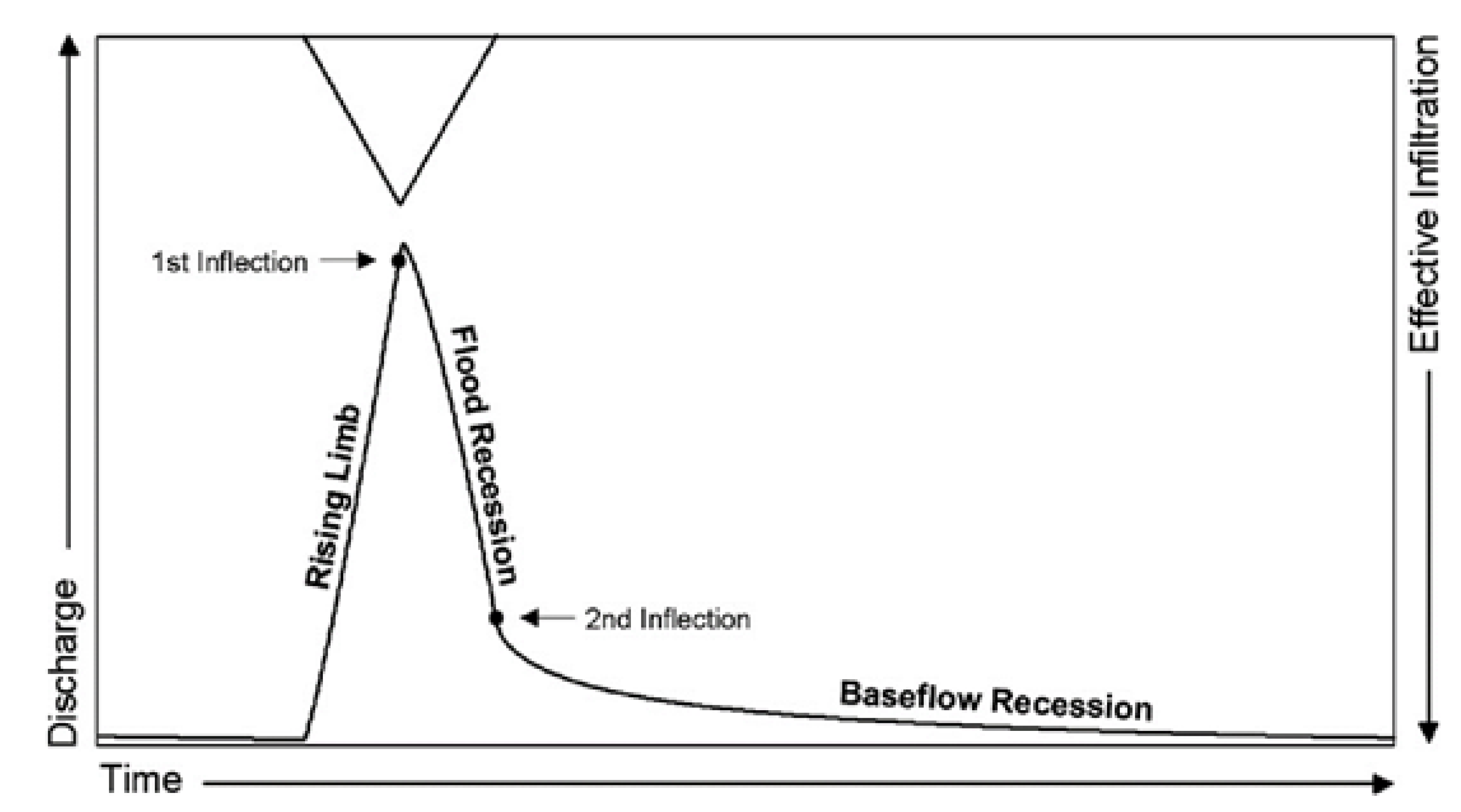
Figure 2. Schematic representation of a spring hydrograph (modified from Kovács and Perrochet [43]).
Water 13 01189 g002
Figure 3. (A) The conceptual model with the plan and 3D view used for the simulation. (B) The plan view of the number of nodes and tubes in the conduit.
Water 13 01189 g003
Figure 4. Spring hydrograph variability in the relation to the exchange coefficient changes in scenarios A1 (A) and B1 (B).
Water 13 01189 g004
Figure 5. Temporal changes of the direction of the exchange flow. The QMC− discharge dominates only in part of the CFR time during rainfall in the karst aquifer and then the QMC+ discharge dominates in a situation with the exchange coefficient of 10−3 m2/s and conduit diameter of 0.5 m.
Water 13 01189 g005
Figure 6. Spring hydrograph variability in relation to conduit diameter changes in scenarios A2 (A) and B2 (B).
Water 13 01189 g006
Figure 7. Spring hydrograph variability in relation to matrix hydraulic conductivity changes in scenarios A3 (A) and B3 (B).
Water 13 01189 g007
Figure 8. Investigation of the response of the spring hydrograph to the changing of values of exchange coefficient, conduit diameter, and matrix hydraulic conductivity for different scenarios of the history of exchange flow direction and different flow regimes as a result the different values of recharge: column (A), CIFR and/or the MRFR with exchange flow QMC+ as a result of low point recharge. Column (B), conduit flow regime in the early time of hydrograph and CIFR and/or the MRFR in the rest of hydrograph time as a result medium point recharge with exchange flow QMC+. Column (C), conduit flow regime with exchange flow QMC− and QMC+ in the early time of the hydrograph and CIFR and/or the MRFR in the rest of time hydrograph as a result of large point recharge.
Water 13 01189 g008
Table 1. The detailed specifications of the scenarios (K is the hydraulic conductivity of the matrix, d is conduit diameter,   k c is roughness, Sy is specific yield, SS is specific storage, and h initial is the initial hydraulic head in the matrix).
Number of Run ModelsVariable ParameterConstant ParametersType of Scenario
A
(QMC+)
(A1)K (10−5 m/s) α e x
(10−2–10−5)
4
d (0.5 m)
    k c   (10−2)
Sy (5 × 10⁻³)
SS (10−7)
hinitial (20 m)
(A2)K (10−5 m/s) d
(0.1–0.5 m)
5
α e x (10−3 m2/s)
k c (10−2)
Sy (5 × 10⁻³)
SS (10−7)
hinitial (20 m)
(A3) d (0.5 m)K
(10−3–10−6)
4
α e x (10−3 m2/s)
    k c   (10−2)
Sy (5 × 10⁻³)
SS(10−7)
hinitial (20 m)
B
(QMC− and QMC+)
(B1)K (10−5 m/s) α e x
(10−2–10−5)
4
d (0.5 m)
k c (10−2)
Sy (5 × 10⁻³)
SS (10−7)
hinitial (20 m)
(B2)K (10−5 m/s) d
(0.1–0.5 m)
5
α e x (10−3 m2/s)
  k c (10−2)
Sy (5 × 10⁻³)
SS (10−7)
hinitial (20 m)
(B3) d (0.5 m)K
(10−3–10−6)
4
α e x (10−3 m2/s)
k c (10−2)
Sy (5 × 10⁻³)
SS (10−7)
hinitial (20 m)
Table 2. Classification of spring hydrographs based on the mechanism of exchange flow.
StateIIIIIIIV
Spring hydrograph Water 13 01189 i001 Water 13 01189 i002 Water 13 01189 i003 Water 13 01189 i004
Recession curve Water 13 01189 i005 Water 13 01189 i006 Water 13 01189 i007 Water 13 01189 i008
Inflection pointClearClearClearUnclear
The position of inflection pointBefore an arc regionBefore a non-arc regionBefore a non-arc region-
ααI, αIII, αIV > αII
Characteristics of the internal structureαexLargeSmallLargeLarge
TSmallSmall or LargeLargeLarge
ΔhΔhI, ΔhIII, ΔhIV < ΔhII
Potential Scenario in the synthetic forward modelingScenario A and BScenario A and BScenario BScenario A
Characteristics of
Scenarios A and B
RCH in Scenario A = RCH in Scenario B
CRCH in Scenario A << CRCH in Scenario B
Aquifer thickness in Scenario A = Aquifer thickness in Scenario B
The effective porosity of the matrix in Scenario A = The effective porosity of the matrix in Scenario B
αex: Exchange coefficient
T: Transmissivity
α: The slope of recession curve under the condition of baseflow
Δh: The difference of the hydraulic head between the matrix and the conduit
RCH: Diffuse recharge to the matrix
CRCH: Concentrated recharge to conduits
Publisher’s Note: MDPI stays neutral with regard to jurisdictional claims in published maps and institutional affiliations.