Article

A Simulation of Salt Transport in NaCl-Laden Soil Barrier to Control Subterranean Termites in an Earth Embankment

1
College of Geomatics and Municipal Engineering, Zhejiang University of Water Resources and Electric Power, Hangzhou 310018, China
2
Zhejiang Institute of Hydraulics and Estuary, Hangzhou 310012, China
*
Author to whom correspondence should be addressed.
Water 2021, 13(9), 1204; https://doi.org/10.3390/w13091204
Submission received: 27 March 2021 / Revised: 22 April 2021 / Accepted: 23 April 2021 / Published: 27 April 2021

Abstract

:
Subterranean termite activity can increase the hydraulic conductivity and water infiltration of filling soil, and therefore affects the stability of an earth embankment and subsequent safety. As a physical barrier for sustainable termite management, NaCl-laden soil barrier (NLSB) is a promising alternative for subterranean termite control in earth embankments. This novel technology can prevent tunneling and penetration of subterranean termites into the interior of an embankment and has been widely employed for more than 20 years in Zhejiang Province, China. The efficacy and longevity of NLSB depend on the long-term presence of NaCl concentration in soil barriers. The aim of this study is to develop an understanding of water flow and salt transport in NLSB based on the two-dimensional Richards’ equation and convection dispersion equation using the HYDRUS software package. Conceptual and numerical models of NLSB are modeled using scenario analysis according to water level fluctuations, saturated hydraulic conductivity, and rainfall infiltration conditions. Furthermore, the center and spread variance of a solute mass over a 100-year period are quantified using moment analysis. As flood frequency, saturated hydraulic conductivity, and rainfall infiltration flux increase, salt desalination in NLSB significantly increases. When the rainfall infiltration flux is 1% of the annual average rainfall, the total amount of salt transport and leaching can increase by 55%. Moreover, these results facilitate better long-term sustainable management of existing sites and optimal design of future NLSBs.

1. Introduction

Termites are among the oldest social insects on Earth [1], with a history of over 250 million years. Currently, there are over 3000 termite species that have been reported in the world [2,3]. As structural or agricultural pests, 476 species of termites are classified into four families and 44 living or fossil genera in China [4]. Among them, termite species that cause serious damage include Coptotermes formosanus Shiraki, Odontotermes formosanus Shiraki, Macrotermes barneyi Light, Reticulitermes flaviceps Oshima, and Reticulitermes chinensis Snyder [5]. They are a serious menace to crops, forests, and various wooden structures [6,7,8] and the most problematic pest that threatens the earth embankments of rivers and reservoirs [9,10,11]. The direct economic losses from termites for Malaysia, India, Australia, China, Japan, and the United States have been reported to be USD 10, 35, 100, 375, 800, and 1000 million a year, respectively [6,12]. In 2010, the impact of termites on the global economy was estimated to be approximately USD 40 billion [13], with subterranean termites accounting for 80% of this number [14].
Subterranean termites are the most widespread and destructive termite group affecting embankment engineering in China. When subterranean termites construct their nests, they dig long, curved tunnels and large internal cavities that can increase the hydraulic conductivity and water infiltration of the filling soil and adversely affect the service life of earth embankments [12,15,16,17]. The most serious structural pest within this group that is capable of causing serious damage to earth embankments is Odontotermes formosanus Shiraki [18,19,20]. Subterranean termites are often not readily noticed because their activities are hidden beneath the ground and they do not cause significant damage over a short period of time. Therefore, it takes a long time before one discovers a colony of termites that has invaded and visibly harmed a structure; termites generally require several years to tunnel and burrow before causing significant damage, which can result in economic losses or major accidents [10,12,21].
Current practices for effectively controlling subterranean termites include the following two major approaches: the barrier technique and the population-control method [22]. The barrier technique prevents termites from having access to feeding and oviposition sites. Various materials and techniques have been used as barriers, including soil termiticide barriers with insecticide, physical barriers with particles (sand, granite, Polynite, glass splinters or globules, marble chips, and volcanic debris), and insecticide-impregnated polymer barriers [6,23,24,25]. The population-control method is predominantly used for termite baiting and has two objectives, i.e., to use a small amount of an active ingredient and to eliminate termite infestations in a large area [26]. Termite bait products for subterranean termite control are generally of two types, i.e., in-ground and above-ground bait systems [27]. Baiting has been the most successful using chitin synthesis inhibitors for controlling subterranean termites and achieving colony elimination. Conventional chemical pesticides that are extensively used cause resistance in termites, toxicity to plants and the environment, and health risk to humans [28]. Su and Scheffrahn [29] proposed a conceptual framework for integrated pest management of termites using baiting as the core technology. Later, it was further developed as sustainable termite management to achieve a socially sustainable potential [14,30].
Table salt, which predominantly contains NaCl, is both toxic and lethal to termites, and therefore has been traditionally used to control the spread of termites [31,32,33,34]. As an alternative to chemical pesticides, table salt for termite control can reduce or eliminate termiticide treatment to a certain extent. Table salt is nonvolatile and robust; hence, it does not evaporate, degrade, or produce odor. This is of paramount importance as it saves cost and reduces the environmental risk of employing strong chemicals against termites. In Zhejiang province of China, NaCl-laden soil barrier (NLSB) against subterranean termites is a popularly used barrier technique for treating earth embankments. The NLSB arrangement with NaCl-laden soils at a NaCl/soil ratio of 0.8% [31] is shown in Figure 1. The use of NLSB to prevent termites from invading embankments is advantageous in that it does not pollute the environment, does not influence the safety of drinking water, and is economic, practical, and simple to implement. This method is easy to set up and execute, and the effectiveness of the termite control period can reach at least 20 years [35].
To discover a scientific explanation for table salt treatment to protect structures from subterranean termite infestation, various tests have been conducted to investigate the effects of NaCl, and certain other chloride and sodium salts on certain important enzymes produced by termites [32,36,37,38,39,40]. Fagbohunka et al. [32,37,38] observed greater inhibitory effect of chloride salt on cellulolytic enzymes than other enzymes. Regarding inhibition of the enzyme activity in the presence of certain metal chloride salts, chloride salts could be employed for preparing a pesticide for termite control [39]. Hu et al. [40] performed a series of experiments to investigate retarding, lethal, and anti-penetrating effects of different types and concentrations of NaCl-laden soil on termites and found that a NaCl/soil ratio of 0.4% mixed soil had good lethal and anti-penetrating effects on termites.
As a novel treatment technology, NLSB has an excellent reputation for safety and performance; however, previous studies about the long residual life of NLSB based on long-term measured data lack complete knowledge and understanding. This restricts the comprehensive promotion of this technology. The efficacy and longevity of NLSB depend on the long-term presence of NaCl concentration in soil barriers. The objective of this study was to determine groundwater and salt transport rules of NLSB in embankments. Hence, HYDRUS was selected for its ability to simulate groundwater and salt transport in porous media of an unsaturated zone. HYDRUS is a software package capable of simulating water, solute, and the heat flow process in variable saturated porous media [41,42,43]. In addition, two-dimensional (2D) Richards and convection dispersion equations were used in HYDRUS-2D for describing groundwater and solute migration. By using scenario analyses based on water level fluctuations, saturated hydraulic conductivity, and rainfall infiltration conditions, along with the moment analysis method, we investigated the change in the characteristics of NaCl concentration in soil barriers. This study contributes to the understanding of salt transport in NLSB for controlling subterranean termites in an earth embankment and optimally to design future NLSB in engineering practice.

2. Materials and Methods

2.1. Structure of NaCl-Laden Soil Barrier (NLSB)

The basis of NLSB technology is to control a termite invasion by adding NaCl in soil (silt loam) to satisfy the specifications of the physical and chemical indices of soil used for filling the embankment [31]. According to the mechanical test of NaCl-laden soil, when NaCl concentration in soil is less than 3%, the physical properties of soil change slightly, which then satisfy the relevant specifications [44]. A nest built by subterranean termites in an earth embankment is generally located 1.0 m below the surface and above the phreatic line of the earth embankment [45]. Figure 2 schematically depicts the NLSB structure in an earth embankment.
In this study, each of the simulations used a 9 m high earth embankment with upstream and downstream slope ratios of 1:3 and 1:2, respectively. The initial low, normal, and high water levels were 2.5, 5.5, and 8.5 m, respectively. NLSB is located 1.0 m below the embankment outline and 1.0 m above the initial phreatic line.
The most common soluble salts (minerals) in soil are calcium, magnesium, sodium, chloride, sulfate, and bicarbonate. The general method to determine the concentration of soluble salt in soil is to measure the electrical conductivity of a soil solution or soil-water extract. This method was used to measure the content of water-soluble salts in the undisturbed soil samples and the results were generally less than 0.1% in situ. The concentration of NaCl in the solid phase of NLSB was 8 g/kg at the beginning of the simulation. Under this concentration, soluble salt has little harmful effect on plant growth. In the laboratory test, in NaCl-laden soil with a concentration of 8 g/kg, all individuals of Coptotermes formosanus Shiraki and Odontotermes formosanus Shiraki died within 22.67 and 5.33 days, respectively [40]. Furthermore, the transport of minerals in soil composition was not considered in the simulation study.

2.2. Numerical Methods

2.2.1. Governing Equations

By considering the isothermal homogeneous Darcy flow in variable saturated rigid porous media and neglecting the effect of gas phase in a liquid flow process, the modified Richards equation is used to describe the water flow [46] as follows:
θ t = × ( K h + K z ) S ,
where t is time (T); h is the pressure head of water (L); θ is the volumetric water content (L3L−3); K(θ) is the unsaturated hydraulic conductivity function (LT−1); ∇ is a vector differential operator (L−1); z is the Cartesian coordinate (L); and S is the general sink term (L3L−3T−1), which is not considered in the calculation.
The water retention properties and hydraulic conductivity of the soil can be estimated using the van Genuchten [47] formulations as follows:
θ ( h ) = { θ r + θ s θ r [ 1 + | α h | n ] m ; h < 0 θ s ; h 0 } ,
K ( θ ) = K s × S e l [ 1 ( 1 S e 1 / m ) m ] 2 ,
where θs and θr are the saturated and residual water contents (L3L−3), respectively; Ks is the saturated hydraulic conductivity (LT−1); Se = (θ − θr)/(θr − θs) is the effective saturation; α (L−1) and n are the empirical constants that are related to inverse air-entry pressure value and pore-size distribution, respectively; and l and m are empirical parameters. Furthermore, we assumed that l = 0.5 and m = 1 − 1/n (n > 1) in the calculation.
As a conservative and nonreactive solute (NaCl), salt transport can be described by the advective-dispersive equation as follows:
θ c t = × ( q c θ D c ) S c ,
where c is the solute concentration (ML−3); q is the volumetric water flux density vector (L3L−2T−1); D is the dispersion tensor (L2T−1); and Sc is the sink term, which is not considered in the calculation. The components of D have been given by Bear [48] as:
θ D = θ D i j = D T | q | δ i j + ( D L D T ) q i q j | q | + θ D d τ δ i j ,
where Dij is the component of the dispersion tensor (L2T−1); DL and DT are longitudinal and transversal dispersivities (L), respectively; Dd is the molecular diffusion coefficient in free water (L2T−1); qk (k = i, j) is the k-component of q (L3L−2T−1); τ is the tortuosity factor; and δij is the Kronecker delta function.
Salt transport in an earth embankment with NLSB is truly a three-dimensional (3D) problem. Therefore, it would be much better to establish a 3D numerical model so that the analysis is closer to reality. However, this might not always be possible because of practical limitations. Numerical two-dimensional (2D) modeling is less complex as compared with 3D modeling and is also less time-consuming. In this study, we used the HYDRUS-2D software package to solve the aforementioned equations. The HYDRUS-2D is based on the Galerkin-type linear finite element program for solving the 2D Richards and convection-dispersion equations.

2.2.2. Model Domain, Initial Hydraulic, and Boundary Conditions

The model domain has a trapezoidal geometry, as illustrated by the cross section AEFIA in Figure 3, demonstrating the physical conditions. AB, AC, and AD depict the upstream area during the dry, normal, and rainy seasons, respectively; AI represents the impervious foundation; EF, GH, and HI represent the embankment crest, seepage face, and tail water area, respectively; and the NLSB area is enclosed in orange. By using the Meshgen tool in the HYDRUS software package, the region was discretized into 2D triangular elements. Each mesh contained approximately 7200 nodes and 14,000 triangular elements. The finite element mesh and boundary conditions of the earth embankment with NLSB are shown in Figure 3.
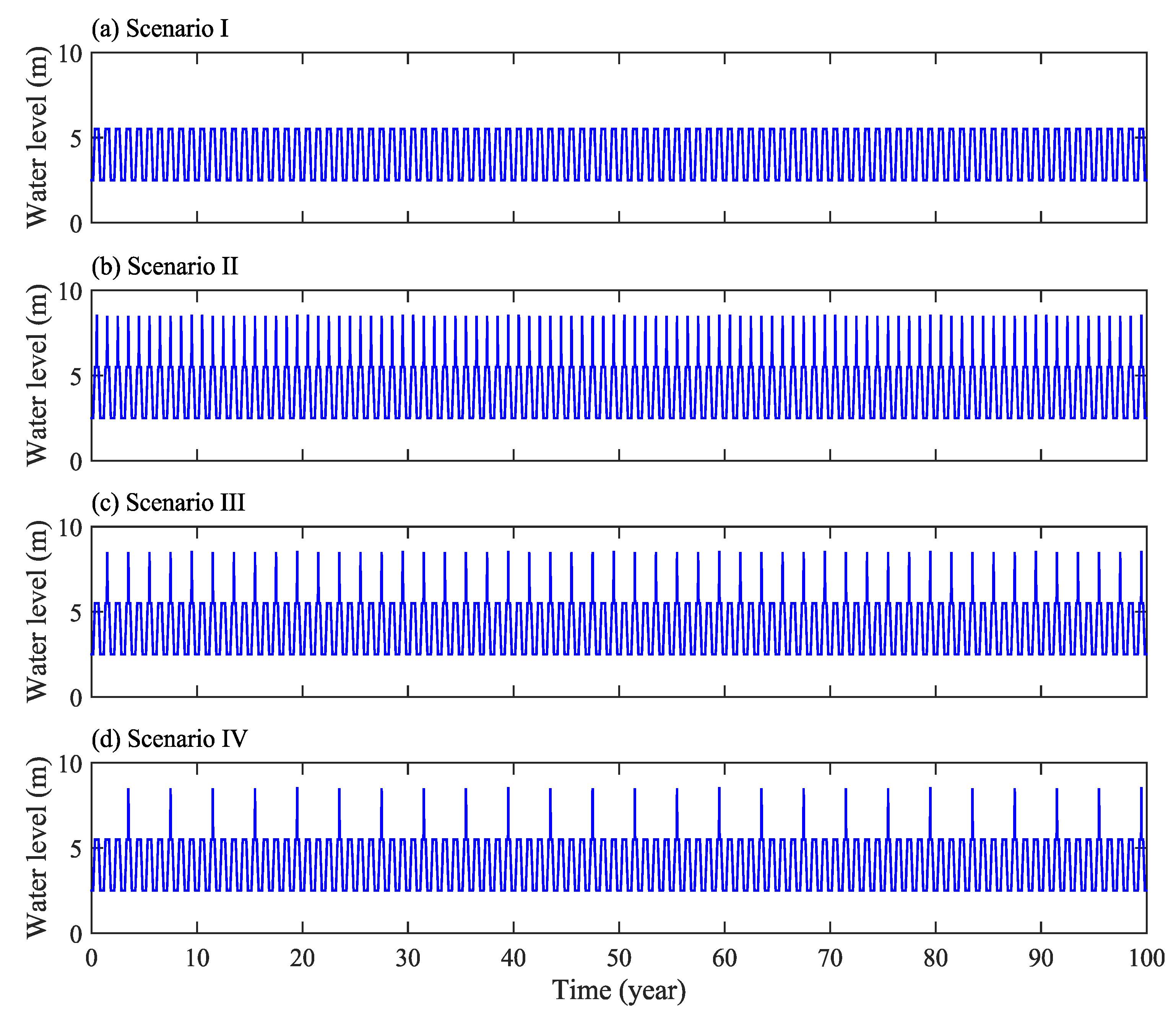
The natural change of water level in the study area is mainly affected by rainfall. The study was conducted in the region of the Qiantang River Basin, Zhejiang Province, China, where the climate is subtropical and humid. This area has an average annual rainfall of approximately 1200 mm. According to the distribution within one year, the rainfall is relatively less from September to December and more from April to July. However, the maximum rainfall usually occurs during the typhoon period in July, and the extremely high water level lasts for 3–5 days. Four scenarios were considered, according to the water level fluctuations on the upstream slope (Figure 3). Scenario I, which corresponds to the normal water year, is set as follows:
h ( t ) = { 2.5 m , 0 t < 60 days , 305 days t 365 days 0.05 t 0.5 m , 60 days t < 120 days 5.5 m , 120 days t < 245 days 17.75 0.05 t m , 245 days t < 305 days
The water level fluctuations in Scenario I are shown in Figure 4a, assuming that there are 100 variable water level cycles, and the total simulation period is 100 years.
Scenario II, which corresponds to the wet year, is set as:
h ( t ) = { 2.5 mm 0 t < 60 days , 305 days t 365 days 0.05 t 0.5 m , 60 days t < 120 days 5.5 m , 120 days t < 170 days , 195 days t < 245 days 0.3 t 45.5 m , 170 days t < 180 days 8.5 m , 180 days t < 185 days 64 0.3 t m , 185 days t < 195 days 17.75 0.05 t m ,   245 days t < 305 days
The water level fluctuations in Scenario II are shown in Figure 4b, assuming 100 variable water level cycles over a total simulation period of 100 years.
The water level fluctuations in Scenario III are shown in Figure 4c, which displays one normal year followed by one wet year, with 50 cycles and a total simulation period of 100 years. The water level fluctuations in Scenario IV are shown in Figure 4d, which presents three normal years followed by one wet year, with 25 cycles and a total simulation period of 100 years.

2.2.3. Parameter Values

Li et al. [45] used the HYDRUS software package and a numerical model based on a 2D Richards equation to analyze the relationship of groundwater flow with the stability of an earth embankment. In the present study, we used the same soil and water characteristic parameters (Table 1) as reported in [45]. The parameter values used in Table 1 were set to reflect the field conditions at the study site in Zhejiang Province, China. The soil matrix (sand 19%, silt 61%, and clay 20%) of earth embankments was specified as silt loam [49]. We used Rosetta, a pedotransfer function package in HYDRUS, to estimate hydraulic conductivity of unsaturated soils in the van Genuchten [47] formulation.
In the scenario analyses, we mainly considered the change of saturated hydraulic conductivity of soil matrix. In the simulation of solute transport, the interaction and adsorption of solutes were not considered, and the hydrodynamic dispersion coefficient was determined using the molecular diffusion coefficient (Dd) in free water and the longitudinal and transverse dispersivities (DL and DT) of solutes. The diffusion coefficient (Dd) of sodium ion in water at 25 °C is 8.99 × 10⁻⁵ m2/days [50]. According to Gelhar’s rule-of-thumb [51], the longitudinal dispersivity is related to the research scale or length of seepage path. Schulze–Makuch [52] established the relationship between the longitudinal dispersivity of solute and the characteristic length of seepage path through a large number of literature reviews on statistical analyses as:
D L = 0.085 L s 0.81 ,
where Ls is the characteristic length of the seepage path. Bear [48] reported that transverse dispersivity (DT) is one tenth of the longitudinal dispersivity (DL) as follows:
D T = 0.1 D L .
In this study, the selected solute longitudinal and transverse dispersivities are DL = 0.45 m and DT = 0.045 m, respectively.

2.3. Moment Analysis

To provide a more quantitative analysis of salt transport in NLSB under various simulation conditions, the moment analysis method is introduced [53] as follows:
M i j ( t ) = Ω θ ( x , z , t ) c ( x , z , t ) x i z j d x d z ,
where Mij is the moment of order with i, j between 0 and 2; Ω is the integration domain of interest; and dx and dz are the changes in the x and z directions, respectively.
The zeroth moment, M00 (M), represents the total solute mass in the system as:
M 00 ( t ) = Ω θ ( x , z , t ) c ( x , z , t ) d x d z .
The first moment is normalized with respect to mass, and xc and zc define the center of solute mass in the x and z directions, respectively, as:
x c ( t ) = Ω θ ( x , z , t ) c ( x , z , t ) x d x d z M 00 ( t ) ,
z c ( t ) = Ω θ ( x , z , t ) c ( x , z , t ) z d x d z M 00 ( t ) .
The second moments corresponding to the spread around the center of mass are normalized with respect to mass, and σxx and σzz define the spread variance of mass in the x and z directions, respectively, as:
σ x x ( t ) = Ω θ ( x , z , t ) c ( x , z , t ) ( x x c ) 2 d x d z M 00 ( t ) ,
σ z z ( t ) = Ω θ ( x , z , t ) c ( x , z , t ) ( z z c ) 2 d x d z M 00 ( t ) .

3. Results

3.1. Scenario Analysis with Respect to Different Water Levels

A no flow boundary was selected along FG (in Figure 3) during simulations for scenarios I–IV. Nine observational positions of flowing particles were set in the calculation domain of NLSB, as shown in Figure 2. Among them, observation Points 1–3 were on the boundary line of NLSB near the upstream slope, observation Points 5–7 were positioned on the boundary line of NLSB near the downstream slope, and observation Points 4, 9, and 8 were positioned on the axis with distance = 0 m. The particle-tracking method was used to calculate the trajectories of moving particles with time. Figure 5 depicts the trajectories of flowing particles under different water levels.
The frequency of floods is mainly considered in the setting of water-level-change scenario at the upstream slope. Figure 5 shows that during floods (Scenarios II, III, and IV) the trajectories of the flowing particles at each observation point deflect toward the downstream slope. An increase in the number of floods increases the deflection angle and movement distance of particles in the specified time. At Point 1, which is nearest to the normal water level of the upstream slope, the particle movement distance of flowing particles in the calculation time domain is the longest, and it can reach the seepage surface of the downstream slope. The deflection angle is the largest, and the maximum deflection angle is 59°.
The cumulative flux of solute in the study area under different water levels is shown in Figure 6. The results indicate that the total amount of solute outside of the NLSB first increases and then decreases with time (Figure 6a), whereas the total amount of solute inside the NLSB decreases gradually (Figure 6b). In addition, the total amount of solute in the cross section of the dam decreases gradually with respect to time; with the solute moving out of the calculation domain from the boundary surface (Figure 6c), and the total amount of salt leaching increasing gradually (Figure 6d).
Further analysis shows that under the calculation condition of Scenario I, when time = 100 years, the average solute concentration inside NLSB decreases from 8 g/kg at the initial time to 3 g/kg, and the average solute concentration outside NLSB increases from 0 to 0.33 g/kg. An increase in flood frequency significantly increased the salt desalination of NLSB. According to Scenario II of a wet year, when time = 100 years and compared with Scenario I, the total amount of solute in the outside of NLSB, in the interior of NLSB, and in the cross section of embankment was reduced by 32%, 31%, and 32%, respectively, and the total amount of salt transport and leaching out of the calculation domain was increased by 45%.
The trajectory of solute centroid under different water levels is shown in Figure 7. The calculation results show that the mass center of solute in the cross section of the embankment, first, moves toward the seepage surface of the downstream slope. With the solute near the phreatic line gradually moving out of the calculation domain from the seepage surface, the mass center tends to move toward the crest of the embankment.
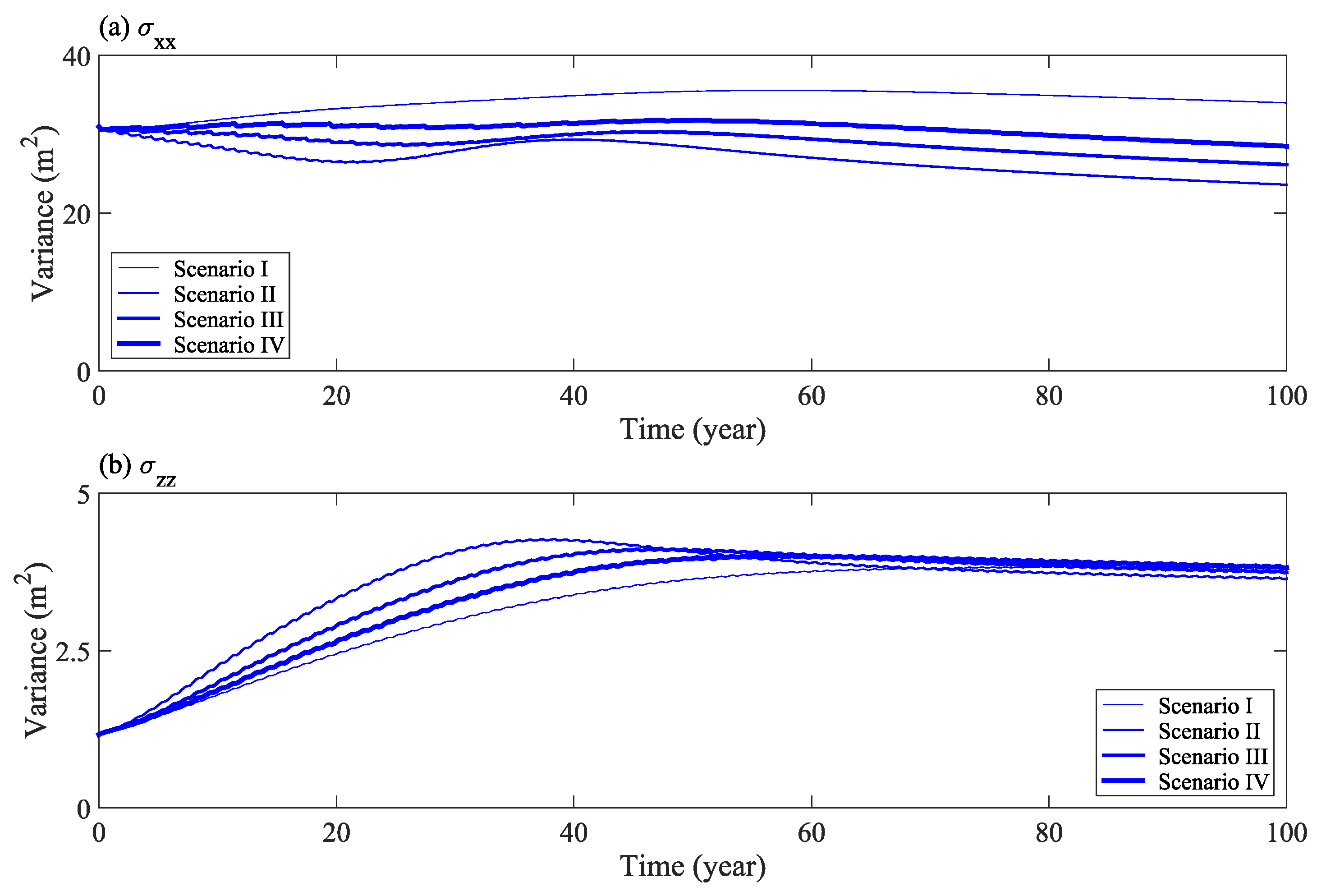
Figure 8 shows the change in the second moment horizontal component (σxx), and vertical component (σzz), of solute distribution with time under different water levels. The results show that with an increase in flood frequency, as more solutes transport out of the calculation domain, the expansion range of solute mass in the horizontal direction becomes narrower (Figure 8a). Furthermore, the expansion range in the vertical direction increases slightly, at first, and then remains constant in the later stage (Figure 8b). Therefore, an increase in flood frequency has a significant impact on the lateral displacement and expansion of solutes in the horizontal direction.

3.2. Influence of Saturated Hydraulic Conductivity

Hydraulic conductivity is a main factor affecting groundwater and salt transport. Under the condition that other parameters remain unchanged, the variable head boundary of the upstream slope was set according to the normal water year (Scenario I). Figure 9 shows the movement trajectory of flowing particles at the observation point under different saturated hydraulic conductivity conditions. The results show that with an increase in soil saturated hydraulic conductivity, the length of particle seepage path increases. However, the inclination angle of seepage path is unchanged, and it points to the seepage surface of downstream slope when time = 100 years.
The cumulative flux of solute in the study area under various saturated hydraulic conductivities is shown in Figure 10. The results show that when the saturated hydraulic conductivity doubled from 0.0108 to 0.0216 m/day, the total amount of solute at the outside of the NLSB, inside the NLSB, and in the cross section of the embankment decreased by approximately 30%, and the total amount of salt transport and leaching increased by 77%. Under the four calculation conditions of saturated hydraulic conductivity, when time = 100 years, the average concentration of solute in the interior of NLSB decreased from 8 g/kg (initial) to 3, 2.1, 0.8, and 0.2 g/kg, respectively. Salt can be leached out by moving to the tail water boundary (HI in Figure 2) and seepage face boundary (GH in Figure 2) in the calculation domain. Considering the saturated hydraulic conductivity of 0.108 m/day as an example, at time = 100 years, the total amount of solute leached out ratio by GH and HI is 365:1; hence, the seepage face is the main channel of solute transport.
The trajectory of solute centroid under different saturated hydraulic conductivity is shown in Figure 11. The results show that with an increase in saturated hydraulic conductivity, the distance of solute transport increases, but the trajectory of mass center moves along the same curve.
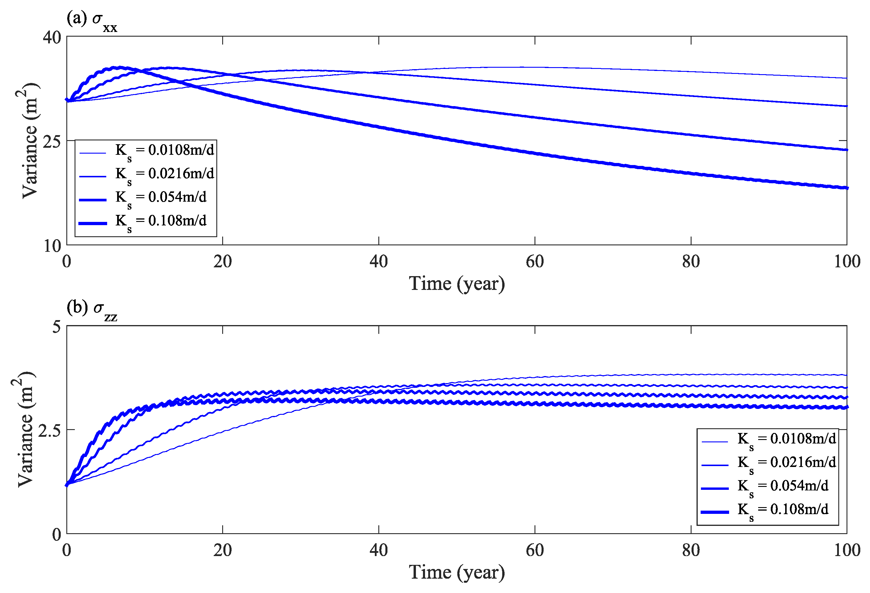
Figure 12 shows the change of the second moment horizontal component (σxx), and vertical component (σzz), of solute distribution with time under various values of saturated hydraulic conductivity. The results show that with an increase in saturated hydraulic conductivity, as more solutes transport out of the calculation domain, the expansion range of solutes in the horizontal direction is narrowed in the later stage (Figure 12a). Furthermore, the expansion range in the vertical direction, first, increases, and then remains stable in the later stage (Figure 12b). Therefore, an increase in soil saturated hydraulic conductivity has a more obvious effect on the horizontal seepage of salt.

3.3. Scenario Analysis under Different Rainfall Infiltration Conditions

Infiltration refers to the process of water entering the soil vertically from the soil surface. For an earth embankment, the precipitation enters the surface of filling soil after being intercepted by revetment and the turf layer. The secondary distribution and transformation of water occurs at the soil interface, including the movement of water in the soil layer and evaporation on the soil surface. Most of the water flows along the slope and converges into surface runoff. In the simulation, the infiltration is assumed to occur only on one side of the downstream slope (FG in Figure 2) and is simplified as a fixed flux boundary. The selected water fluxes are 12, 24, and 60 mm/year, which are equivalent to 1%, 2%, and 5%, respectively, of the annual average rainfall (1200 mm) in the study area.
Under the condition that other parameters remain unchanged, the variable head boundary of upstream slope was set according to the normal water year (Scenario I). Figure 13 shows the trajectory of flowing particles at the observation point under different rainfall infiltration conditions. The results show that under the condition of considering rainfall infiltration, the surface soil water content of the downstream slope increases rapidly, water moves downward under the action of gravity and capillary force, and gradually infiltrates the deep soil. Moreover, the infiltration flux of downstream slope leads to the deflection of the trajectory of particles at observation Points 4–9 with the maximum deflection angle of 123°. With an increase in rainfall infiltration flux, the deflection angle and transport distance of particle trajectory increase.
The cumulative flux of solute in the study area under different rainfall infiltration conditions is shown in Figure 14. Considering the rainfall infiltration, the movement of water and salt is accelerated. The results show that when the rainfall infiltration flux increases from 0 to 12 mm/year, the total amount of solute at the outside of NLSB, inside the NLSB, and at the cross section of the dam decrease by 24%, 17%, and 20%, respectively, and the total amount of salt leaching increases by 55%. Under the four conditions of infiltration flux calculation, when time = 100 years, the average concentration of solute in NLSB decreases from 8 g/kg to 3, 2.5, 2.0, and 1.5 g/kg, respectively.
The trajectory of solute centroid under different rainfall infiltration conditions is shown in Figure 15. The results show that the center of mass, first, moved toward the seepage surface of the downstream slope. Next, with an increase in rainfall infiltration, the solute near the side of the downstream slope gradually moved out of the calculation domain from the seepage surface, and the center of mass tended to deflect to the upstream slope.
Figure 16 shows the changes of horizontal component (σxx) and vertical component (σzz) of the second moment in the solute distribution with respect to time under different rainfall infiltration conditions. Figure 16 shows that after the infiltration water flux increases, the expansion range of solute in the horizontal direction increased in the early stage of calculation (Figure 16a). In the later stage, with the solute near the downstream slope being washed clean, the expansion range of solute around the center of mass became narrower. In the vertical direction, the expansion range increased significantly with an increase in infiltration flux and remained constant in the last 50 years (Figure 16b). Therefore, an increase of infiltration water flux has a significant effect on the salt transport near the downstream slope.

4. Discussion

We have identified a novel technology using NLSB for subterranean termite control as a physical barrier against the oldest known record of social insects in Zhejiang Province, China. However, to the best of our knowledge, there are no reports of the long residual life of NLSB based on long-term measured data. The aim of the present numerical simulation is to reveal the long-term presence of NaCl concentration in soil barriers and verify the efficacy and longevity of NLSB in an earth embankment. Recent studies [41,42,43] have shown that HYDRUS-2D was a suitable program to use for this purpose. In the present study, under rising and drawdown of the water level at the upstream slope, groundwater transport from upstream to downstream of the earth embankment is driven by water potential gradients. With the movement of water, solute mass in soil barriers gradually spreads, and then expands in response to water content and solute concentration gradients. With an increase in saturated hydraulic conductivity of the soil matrix, the average velocity of soil water and salt transport increased. Rainfall infiltration enhanced soil water potential gradients on the downstream slope. As a result, the high hydraulic gradients could make a significant salt leaching and desalination in NLSB, which is in line with previous studies [54,55].
Most embankment projects in paddy field areas comprise an earth embankment. The route is long, the total volume is large, the earth material yard is relatively scattered, and thickness of the soil layer and water content of the soil material along the line are not uniform; all these collectively determine that the type and quality of filling soil material are not unified. Most earth embankments only block the flood for a short time period; hence, the selection range of soil particle size is relatively wide. The materials used can range from the finest clay to silt, sand, gravel, and rock, and the clay content in filling soil is 10−35% [56]. For example, in the paddy field areas on both sides of the Qiantang River in China, most of the concrete faced sloping earth embankments were built in the process of river reclamation after the 1960s. Generally, the filling materials are mainly silt loam and earth-fill and may be zoned with several materials as separate components [45]. Field investigations have shown that termites often choose silt clay or silt loam as the nesting soil layer [57], which is not only conducive to the stability of the nest system itself but also can ensure that the temperature and humidity in the nest are in a relatively stable state. This is beneficial to the activities of termites and reproduction of fungus. Consequently, the selection of soil parameters in this study is representative, but there is a lack of field observation results that can be used for verification. The results of this study are mainly based on numerical simulation, but even the most complex mathematical model is only an approximate treatment of engineering problems. Simultaneously, as the complexity of the model increases, the strictness of the requirement of parameter accuracy increases, and it is difficult to obtain accurate parameters in practice. Therefore, further prospective simulation analysis of the salt transport mechanism of NLSB should be verified by a large number of field test results. Meanwhile, when NaCl is introduced into soil, further in-depth investigations on the soil physical and chemical properties are required in order to fully establish its influence on the biological mechanism for subterranean termite control.
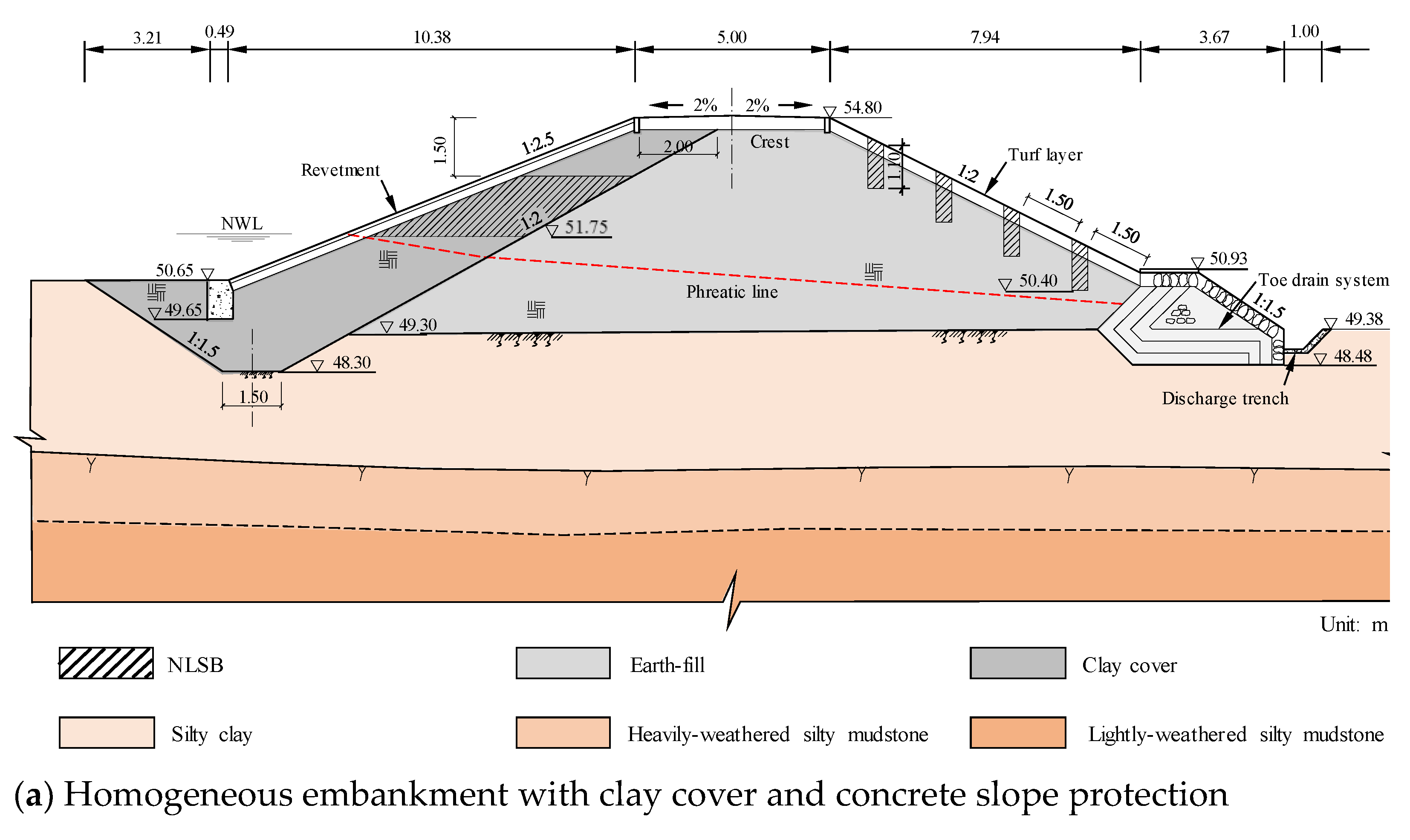
Termites living in an earth embankment are hidden and cannot be easily found. The damage caused by the termites to the dams is often serious by the time they are discovered [10,12,21]. Therefore, potential termite damage should be prevented to reinforce the built embankment without termite damage. The examples of the scenario analysis indicate that when the upstream slope experiences water level fluctuations and the downstream slope withstands rainfall infiltration, the salt leaching in NLSB is intensified. As shown in Figure 17, when reinforcing the earth embankment in engineering practice, considering the site conditions, the excavation is generally conducted at the upstream slope and downstream slope, original filling material is removed, and impervious NaCl-laden soil is used for backfilling. Generally, a termite nest is built 1.0 m below the surface of the embankment and above the phreatic line. Hence, the excavation depth on the slope should be more than 1.0 m, pore diameter should be 40 cm, and proportion of salt and soil in the impervious NaCl-laden soil should be 0.8%. For the core dam, to lower the phreatic line, opening holes along the dam axis are added to reach the underlying layer, and then the impervious clay is backfilled to the phreatic line elevation. Finally, salt should be mixed into the impervious clay in proportion; then, the clay and salt should be mixed evenly, and then backfilled and tamped to form NLSB, which can achieve better control effect. The results of this study uniquely and substantially contribute to the state of knowledge regarding the long residual life of NLSB. This knowledge can be directly applied to the design and construction standards of agricultural embankments, and ultimately can reduce the risk and scope of damage related to earth embankment destruction events.

5. Conclusions

On the basis of the HYDRUS model, we used the Richards equation of water flow in unsaturated porous media and a convection dispersion equation of solute transport to describe the movement characteristics of water and salt in NLSB of an earth embankment. Coupled with a moment analysis method, scenario analyses were conducted by varying the water level, saturated hydraulic conductivity and rainfall infiltration conditions.
The analysis of change in the water levels showed that an increase in flood frequency has a significant impact on the lateral displacement and expansion of salt. The desalination of salt in NLSB is intensified with an increase in flood frequency; however, it mainly affects the salt movement on the side of the upstream slope. According to the calculation conditions of the wet year scenario, the total amount of salt movement and leaching increases by 45%. Hydraulic conductivity is among the main factors affecting soil water and salt transport. The numerical results show that with an increase in saturated hydraulic conductivity, the average speed of soil water and salt transport increases, and the time required for solute to transport to the seepage surface of downstream slope decreases. However, the response of the horizontal transport of solute to hydraulic conductivity is more sensitive. When the saturated hydraulic conductivity of soil increases by one time, the total amount of salt transport and leaching increases 77%. Under the condition of rainfall infiltration, the surface soil-water content of the downstream slope increases rapidly, and water moves downward under the action of gravity and capillary force, and gradually infiltrates into the deep soil. With an increase in infiltration flux, the average speed of soil water and salt movement increases significantly, and the salt desalination on the side of the downstream slope is the fastest. When the rainfall infiltration flux is 1% of the annual average rainfall, the total amount of salt transport and leaching can increase by 55%.
This study could contribute to the understanding of the change in the characteristics of NaCl concentration in soil barriers for subterranean termite control in an earth embankment and facilitate better long-term sustainable management of existing sites and optimal design of future NLSB. Therefore, our research is of particular interest and use to professionals in academia and industry who are interested in minimizing and preventing termite-related engineering failures. In the future, field tests are required to enhance the awareness of groundwater flow and salt transport in an earth embankment with the use of NLSB.

Author Contributions

Conceptualization, writing—original draft preparation, and funding acquisition, Y.L.; methodology, software, and formal analysis, Y.L. and D.-Z.P.; writing—review and editing, D.-Z.P. All authors have read and agreed to the published version of the manuscript.

Funding

This research was funded by the Public Welfare Technology Application Research Project of Zhejiang Province in China, grant number LGF19E090010.

Institutional Review Board Statement

Not applicable.

Informed Consent Statement

Not applicable.

Data Availability Statement

No new data were created or analyzed in this study. Data sharing is not applicable to this article.

Acknowledgments

The authors gratefully thank the associate editor and three anonymous reviewers for their constructive comments and suggestions.

Conflicts of Interest

The authors declare no conflict of interest.

References

  1. Martinez-Delclos, X.; Martinell, J. The oldest known record of social insects. J. Paleontol. 1995, 69, 594–599. [Google Scholar] [CrossRef]
  2. Krishna, K.; Grimaldi, D.A.; Krishna, V.; Engel, M. Treatise on the Isoptera of the world. Bull. Am. Mus. Nat. Hist. 2013, 377, 1–200. [Google Scholar] [CrossRef]
  3. Chouvenc, T.; Li, H.-F.; Su, N.-Y. Connecting termite researchers from around the world at ICE 2016. Am. Entomol. 2018, 64, 152–154. [Google Scholar] [CrossRef]
  4. Huang, F.-S.; Zhu, S.-M.; Ping, Z.-M.; He, X.-S.; Li, G.-X.; Gao, D.-R. Fauna Sinica, Insecta, Vol. 17, Isoptera; China Science Publishing: Beijing, China, 2000. [Google Scholar]
  5. Hu, Y.; Yu, B.-T.; Yin, X.-J.; Song, X.-G. Advance in the development of attractive lignocelluloses materials of termite in China. Chin. J. Hyg. Insect. Equip. 2018, 24, 396–399. [Google Scholar]
  6. Verma, M.; Sharma, S.; Prasad, R. Biological alternatives for termite control: A review. Int. Biodeterior. Biodegrad. 2009, 63, 959–972. [Google Scholar] [CrossRef]
  7. Kuswanto, E.; Ahmad, I.; Dungani, R. Threat of subterranean termites attack in the Asian countries and their control: A review. Asian J. Appl. Sci. 2015, 8, 227–239. [Google Scholar] [CrossRef] [Green Version]
  8. Evans, T.A.; Forschler, B.T.; Grace, J.K. Biology of invasive termites: A worldwide review. Annu. Rev. Entomol. 2013, 58, 455–474. [Google Scholar] [CrossRef] [Green Version]
  9. Bayoumi, A.; Meguid, M.A. Wildlife and safety of earthen structures: A review. J. Fail. Anal. Preven. 2011, 11, 295–319. [Google Scholar] [CrossRef]
  10. Henderson, G. The termite menace in New Orleans: Did they cause the floodwalls to tumble? Am. Entomol. 2008, 54, 156–162. [Google Scholar] [CrossRef] [Green Version]
  11. Huang, Q.; Sun, P.; Zhou, X.; Lei, C. Characterization of head transcriptome and analysis of gene expression involved in caste differentiation and aggression in Odontotermes formosanus (Shiraki). PLoS ONE 2012, 7, e50383. [Google Scholar] [CrossRef] [PubMed]
  12. Ghaly, A.; Adwards, S. Termite damage to buildings: Nature of attacks and preventive construction methods. Am. J. Eng. Appl. Sci. 2011, 4, 187–200. [Google Scholar] [CrossRef]
  13. Rust, M.K.; Su, N.Y. Managing social insects of urban importance. Annu. Rev. Entomol. 2012, 57, 355–375. [Google Scholar] [CrossRef] [PubMed]
  14. Su, N.-Y. Development of baits for population management of subterranean termites. Annu. Rev. Entomol. 2019, 64, 115–130. [Google Scholar] [CrossRef]
  15. Tian, W.-J.; Ke, Y.-L.; Zhuang, T.-Y.; Wang, C.-X.; Li, M.; Liu, R.-Q.; Mao, W.-G.; Zhang, S.-S.; Li, D. A review of the research on dike-infesting termites in China (Isoptera: Termitidae). Sociobiology 2008, 52, 751–760. [Google Scholar]
  16. Yang, X.; Henderson, G.; Mao, L.; Evans, A. Application of ground penetrating radar in detecting the hazards and risks of termites and ants in soil levees. Environ. Entomol. 2009, 38, 1241–1249. [Google Scholar] [CrossRef] [PubMed] [Green Version]
  17. Umaru, A.B.; Sangodoyin, A.Y.; Oke, I.A. On the causes and effects of earth dams failures in north-eastern Nigeria. Int. J. Eng. Res. Technol. 2014, 3, 2978–2985. [Google Scholar]
  18. Mo, J.; Yang, T.; Song, X.; Cheng, J. Cellulase activity in five species of important termites in China. Appl. Entomol. Zool. 2004, 39, 635–641. [Google Scholar] [CrossRef] [Green Version]
  19. Hu, J.; Zhong, J.-H.; Guo, M.-F. Foraging territories of the black-winged subterranean termite Odontotermes formosanus (Isoptera: Termitidae) in southern China. Sociobiology 2006, 48, 1–12. [Google Scholar]
  20. Tian, W.-J.; Ke, Y.-L.; Zhuang, T.-Y.; Wang, C.-X.; Li, M.; Liu, R.-Q.; Mao, W.-G.; Zhang, S.-S.; Li, D. Incipient colony development and biology of Odontotermes formosanus (Shiraki) and O. hainanensis (Light) (Isoptera: Termitidae). J. Agric. Urban. Entomol. 2009, 26, 147–156. [Google Scholar] [CrossRef]
  21. Li, D.; Tian, W.-J.; Li, M.; Chen, L.-L.; Meng, Q.-Z.; Mao, W.-G.; Li, Z.-P.; Huang, J.-P. Distinction between termite-induced piping in dikes and that caused by physical factors, and its treatment. Acta Entomol. Sin. 2004, 47, 645–651. [Google Scholar]
  22. Su, N.-Y. Novel technologies for subterranean termite control. Sociobiology 2002, 39, 1–7. [Google Scholar]
  23. Acda, M.N. Sustainable termite management using physical barriers. In Termites and Sustainable Management, Susttainability in Plant and Crop Protection; Khan, M.A., Ahmad, W., Eds.; Springer International Publishing AG: Cham, Switzerland, 2018. [Google Scholar]
  24. Acda, M.N.; Ong, H.B. Use of volcanic debris as physical barrier against the Philippine milk termite (Isoptera: Rhinotermitidae). Sociobiology 2005, 46, 117–130. [Google Scholar]
  25. Lewis, V.R.; Haverty, M.I.; Carver, D.S.; Fouche, C. Field comparison of sand or insecticide barriers for control of Reticulitermes spp. (Isoptera: Rhinotermitidae) infestation in homes in northern California. Sociobiology 1996, 28, 327–335. [Google Scholar]
  26. Evans, T.A.; Iqbal, N. Termite (order Blattodea, infraorder Isoptera) baiting 20 years after commercial release. Pest. Manag. Sci. 2015, 7, 897–906. [Google Scholar] [CrossRef]
  27. Su, N.-Y. A fluid bait for remedial control of subterranean termites. J. Econ. Entomol. 2015, 108, 274–276. [Google Scholar] [CrossRef]
  28. Verma, S.; Sharma, S.; Malik, A. Termiticidal and repellency efficacy of botanicals against Odontotermes obesus. Int. J. Res. Biosci. 2016, 5, 52–59. [Google Scholar]
  29. Su, N.-Y.; Scheffrahn, R.H. A review of subterranean termite control practices and prospects for integrated pest management programs. J. Integr. Pest. Manag. 1998, 3, 1–13. [Google Scholar] [CrossRef]
  30. Su, N.-Y. Technological needs for sustainable termite management. Sociobiology 2011, 58, 229–239. [Google Scholar]
  31. Chen, L.-H.; Pan, C.-H.; Chen, S.-M.; Song, X.-G.; Zheng, S.-Z.; Chen, S.-H. New technology of using salt to prevent termites for dikes and dams. Chin. J. Geotech. Eng. 2011, 33, 140–144. [Google Scholar]
  32. Fagbohunka, B.S.; Edorh, S.E.; Adeyanju, M.M.; Ezima, E.N.; Alabi, M.A.; Ogunlabi, O.O. Activities of a cellulase of the termite, Ametermes Eveuncifer (Silverstri) soldier: Clue to termites salt intolerance. J. Nat. Sci. Res. 2015, 5, 117–123. [Google Scholar]
  33. Maayiem, D.; Bernard, B.N.; Irunuoh, A.O. Indigenous knowledge of termite control: A case study of five farming communities in Gushegu District of Northern Ghana. J. Entomol. Nematol. 2012, 4, 58–64. [Google Scholar]
  34. Li, Y.; Dong, Z.-Y.; Pan, D.-Z.; Pan, C.-H. Effect of termite on soil pH and its application for termite control in Zhejiang Province, China. Sociobiology 2017, 64, 317–326. [Google Scholar] [CrossRef] [Green Version]
  35. Chen, L.-H. Cause and control of termite infestation at the northern seawall of Qiantang River. Zhejiang Hydrotech. 2002, 2, 34–35. [Google Scholar]
  36. Alkali, U.U.; Muktar, A. Effect of locally prepared compounds on the resistance of gum Arabic wood to termite attack. J. Environ. Iss. Agri. Devel. Count. 2011, 3, 128–132. [Google Scholar]
  37. Fagbohunka, B.S.; Ezima, E.N.; Adeyanju, M.M.; Alabi, M.A.; Oyedele, D.E.; Adeneye, A.A. Inhibition studies of some key enzymes of the termite Amitermes eveuncifer (Silverstri) workers: Clue to termites salt intolerance. Sci. Focus 2014, 19, 81–87. [Google Scholar]
  38. Fagbohunka, B.S.; Okonji, R.E.; Adenike, A.Z. Purification and characterization of cellulase from Termite Ametermes eveuncifer (Silverstri) soldiers. Int. J. Biol. 2017, 9, 1–9. [Google Scholar] [CrossRef] [Green Version]
  39. Javaheri-Kermani, M.; Asoodeh, A. A novel beta-1,4 glucanase produced by symbiotic Bacillus sp. CF96 isolated from termite (Anacanthotermes). Int. J. Biol. Macromol. 2019, 131, 752–759. [Google Scholar] [CrossRef] [PubMed]
  40. Hu, Y.; Song, X.-G.; Chen, L.-H.; Ruan, G.-H.; Zhou, Y.-Q. Effect of saline soil in controlling termites. Chin. J. Vector Biol. Control 2014, 25, 148–151. [Google Scholar]
  41. Silva, J.A.K.; Simunek, J.; McCray, J.E. A modified HYDRUS model for simulating PFAS transport in the vadose zone. Water 2020, 12, 2758. [Google Scholar] [CrossRef]
  42. Dominguez-Nino, J.M.; Arbat, G.; Raij-Homan, I.; Kisekka, I.; Girona, J.; Casadesus, J. Parameterization of soil hydraulic parameters for HYDRUS-3D simulation of soil water dynamics in a drip-irrigated orchard. Water 2020, 12, 1858. [Google Scholar] [CrossRef]
  43. Ghazouani, H.; Rallo, G.; Mguidiche, A.; Latrech, B.; Douh, B.; Boujelben, A.; Provenzano, G. Assessing Hydrus-2D model to investigate the effects of different on-farm irrigation strategies on potato crop under subsurface drip irrigation. Water 2019, 11, 540. [Google Scholar] [CrossRef] [Green Version]
  44. Chen, S.; Shen, S.; Chen, L.; Lu, G. Test of engineering properties of impervious soil with salt. Adv. Sci. Technol. Water Resour. 2015, 35, 66–70. [Google Scholar]
  45. Li, Y.; Dong, Z.-Y.; Pan, D.-Z.; Pan, C.-H. Effects of subterranean termite nest architectures on earth embankment seepage and stability. Paddy Water Environ. 2020, 18, 367–384. [Google Scholar] [CrossRef]
  46. Simunek, J.; van Genuchten, M.T.; Sejna, M. The HYDRUS Software Package for Simulating Two-and Three Dimensional Movement of Water, Heat, and Multiple Solutes in Variably-Saturated Porous Media, Technical Manual, Version 2.0; PC Progress: Prague, Czech Republic, 2012. [Google Scholar]
  47. Van Genuchten, M.T. A closed-form equation for predicting the hydraulic conductivity of unsaturated soils. Soil Sci. Soc. Am. J. 1980, 44, 892–898. [Google Scholar] [CrossRef] [Green Version]
  48. Bear, J. Dynamics of Fluid in Porous Media; Elsevier: New York, NY, USA, 1972. [Google Scholar]
  49. IUSS Working Group WRB. World Reference Base for Soil Resources 2014, International Soil Classification System for Naming Soils and Creating Legends for Soil Maps, Update 2015; World Soil Resources Reports No. 106; FAO: Rome, Italy, 2015. [Google Scholar]
  50. Rowe, R.K.; Badv, K. Advective-Diffusive contaminant migration in unsaturated sand and gravel. J. Geotech. Eng. 1996, 122, 965–975. [Google Scholar] [CrossRef]
  51. Gelhar, L.W. Stochastic Subsurface Hydrology; Prentice-Hall: Englewood Cliffs, NJ, USA, 1993. [Google Scholar]
  52. Schulze-Makuch, D. Longitudinal dispersivity data and implications for scaling behavior. Ground Water 2005, 43, 443–456. [Google Scholar] [CrossRef] [PubMed]
  53. Singha, K.; Gorelick, S.M. Saline tracer visualized with three-dimensional electrical resistivity tomography: Field-scale spatial moment analysis. Water Resour. Res. 2005, 41, 1–17. [Google Scholar] [CrossRef]
  54. Ahn, T.; Desai, C.S. Stability of earth dam contaminated by chemical transport. Int. J. Numer. Anal. Meth. Geomech. 1999, 23, 1893–1908. [Google Scholar] [CrossRef]
  55. Gulsen, F.; Inui, T.; Kato, T.; Takai, A.; Katsumi, T. Numerical investigation on utilization of natural contaminated soil in the Embankments. In Proceedings of the 8th International Congress on Environmental Geotechnics, Hangzhou, China, 28 October–1 Noveber 2018; Volume 1, pp. 444–451. [Google Scholar]
  56. Ministry of Water Resources of China. Code for Design of Levee Project; (GB 50286-2013); China Planning Press: Beijing, China, 2013. [Google Scholar]
  57. Wang, D.X. Animal and plant communities and the protection of seawall in the south of the Yangtze River in the Qing dynasty. Collect. Essays Chin. Hist. Geogr. 2003, 18, 92–101. [Google Scholar]
Figure 1. Schematic of termite control by using NaCl-laden soil barrier (NLSB). (a) In a homogeneous embankment; (b) in a zoned embankment.
Water 13 01204 g001
Figure 2. Schematic of NaCl-laden soil barrier, including initial hydraulic and boundary conditions used during simulations. (i) Crest; (ii) impervious foundation; (iii) tail water level; (iv) normal water level (NWL); (v) initial water level (IWL); (vi) high water level (HWL); (vii) phreatic line at NWL; (viii) NaCl-laden soil. Positions of observation points (1–9) are marked by red circles.
Water 13 01204 g002
Figure 3. Model domain, FEM mesh, and boundary conditions for an earth embankment with NaCl-laden soil barrier.
Water 13 01204 g003
Figure 4. Water level fluctuations along the upstream slope during simulations: Scenario I (a), Scenario II (b), Scenario III (c), Scenario IV (d).
Water 13 01204 g004
Figure 5. Trajectories of flowing particles under different water levels.
Water 13 01204 g005
Figure 6. Change of solute mass in the study area under different water levels: Outside NLSB (a), NLSB (b), Total across section (c), Salt leaching (d).
Water 13 01204 g006
Figure 7. Center trajectories of solute mass under different water levels.
Water 13 01204 g007
Figure 8. Second moment of solute distribution (horizontal σxx (a) and vertical σzz (b) components) under different water levels.
Water 13 01204 g008
Figure 9. Movement trajectories of flowing particle under various saturated hydraulic conductivities.
Water 13 01204 g009
Figure 10. Solute mass change in the study area under various saturated hydraulic conductivities.
Water 13 01204 g010
Figure 11. Center of solute mass under various saturated hydraulic conductivities.
Water 13 01204 g011
Figure 12. Second moment of solute distribution (horizontal σxx (a) and vertical σzz (b) components) under various saturated hydraulic conductivities.
Water 13 01204 g012
Figure 13. The trajectories of flowing particles under different rainfall infiltration conditions.
Water 13 01204 g013
Figure 14. Solute mass change in the study area under different rainfall infiltration conditions.
Water 13 01204 g014
Figure 15. Center of solute mass under different rainfall infiltration conditions.
Water 13 01204 g015
Figure 16. Second moment of solute distribution (horizontal σxx (a) and vertical σzz (b) components) under different rainfall infiltration conditions.
Water 13 01204 g016
Figure 17. Conventional sketches of NaCl-laden soil barriers design in engineering practice: (a) Homogeneous embankment with clay cover and concrete slope protection and (b) Zoned embankment with low permeable core and concrete slope protection.
Water 13 01204 g017aWater 13 01204 g017b
Table 1. Physical parameters of the soil matrix.
ParameterSoil Matrix
Residual water content, θr (m3m−3)0.02
Saturated water content, θs (m3m−3)0.42
Empirical parameter, α (m−1)0.3
Empirical parameter, n1.3
Empirical parameter, l0.5
Saturated hydraulic conductivity,
Ks0 (md−1)0.0108
Ks1 (md−1)0.0216
Ks2 (md−1)0.054
Ks3 (md−1)0.108
Publisher’s Note: MDPI stays neutral with regard to jurisdictional claims in published maps and institutional affiliations.