Article

Riverbed Morphologies Induced by Local Scour Processes at Single Spur Dike and Spur Dikes in Cascade

1
School of Naval Architecture, Ocean and Civil Engineering, Shanghai Jiao Tong University, Shanghai 200240, China
2
School of Engineering, University of Basilicata, I-85100 Potenza, Italy
*
Authors to whom correspondence should be addressed.
Water 2023, 15(9), 1746; https://doi.org/10.3390/w15091746
Submission received: 24 March 2023 / Revised: 22 April 2023 / Accepted: 30 April 2023 / Published: 1 May 2023
(This article belongs to the Special Issue Sediment Transport at Bridges and River Training Structures)

Abstract

:
Spur dikes are elongated structures extending from banks into rivers that mitigate erosion by forcing the flow away from the bank. The research on grouped spur dikes is insufficient in comparison with those on isolated spur dikes. Most of the studies focus on the maximum scour depth, omitting the bed morphological changes induced by local scour processes. Moreover, as yet, there is no established procedure for predicting the scour depth around spur dikes. This study aims to provide insights into the temporal and spatial morphological patterns around a single spur dike and spur dikes in cascade (three, five, and seven, consecutively). Experiments (of up to 318 h) were performed on a rectangular straight channel with dimensions of 20 m (length) × 1.0 m (width) × 1.0 m (depth). Nearly uniform sand with median grain size of 1.7 mm and sediment gradation of 1.5 was used for the mobile bed. The spacing between the elements for the spur dikes in cascade was 3b, where b is the spur dike width. All runs were conducted under a clear-water regime and steady flow conditions. Some limitations of the formulas for the equilibrium scour depth at the first spur dike reported in the literature were emphasised, with underestimations up to 160% and overestimations up to 200% at the earlier scour stages. The temporal evolution of the scour depth at the first spur dike was satisfactorily predicted with a correlation coefficient of 0.91. The scour processes at the other spur dikes were delayed and started at a dimensionless time greater than approximately 103. However, the scour rates increased to a high degree, with the scour depths tending to match those at the first spur dike.

1. Introduction

Groynes, or spur dikes, are elongated hydraulic structures with one end at the river bank and the other extending outward into the river, and have been employed for river training practices since ancient times. The main function of spur dikes is to protect eroding stream banks. They have also been used to aid in navigation; further, they enhance aquatic habitats by producing stable pools in unstable and disturbed streams. As spur dikes cause deposition, they may protect streambanks more effectively and at a lower cost compared with revetments. Spur dikes are typically built in groups of two or more and may be at right angles to the bank, angled upstream, or angled downstream. The crests of individual spur dikes may level or slope from the bank toward the channel. They can be constructed from various materials, including masonry, concrete, earth and stone, steel, timber sheet-piling, gabions, timber fencing, and weighted brushwood facilities [1].
An intense vortex action tends to develop at the outward end of the spur dike. Lower strength intermittent vortices occur along both the upstream and downstream faces of the spur dike. This turbulence causes the bed material to be suspended, thus rendering it easy for the current to carry it downstream. The depth of the scour hole that develops around a spur dike and the angle of repose of the bed material are the primary factors determining the extent of bank erosion near the spur dike [2].
The literature review below is not exhaustive, and considers both pioneering and recent studies on local scour processes around spur dikes, based primarily on laboratory experiments.
The oldest study on local scour around spur dikes was conducted by Inglis [3], who proposed Lacey’s regime formula in a straight channel. According to this formula, the effective flow depth, DL, in a straight channel and in regime conditions is given (in dimensional form) by 0.47·(Q/f)1/3, where Q is the discharge and f is Lacey’s silt factor, thus approximating to 1.76·(d50)0.5, with d50 being the median grain size of the bed sediment. Inglis [3] highlighted how spur dikes projected from banks yield varying scour values, ranging from 1.7 to 3.8DL, depending on the severity of the river curvature and the length, angle, and position of the spur dike relative to the flow attack.
Garde et al. [4,5] conducted several experiments using a 20 ft long and 2 ft wide glass-walled flume. Four sand sizes were tested with median grain sizes of 0.29, 0.45, 1.00, and 2.25 mm, respectively. The values of the opening ratio α, defined as (Bb)/B, with b and B spur dikes and channel widths, were 0.530, 0.667, 0.835, and 0.900, respectively. The runs lasted from 3 to 5 h, and for the most part, were performed under a clear-water regime. However, upstream sediment transport was high in a few runs, and the sediment was fed manually at the upstream end.
Cuhna [6] performed several tests on a 10 m long, 2 m wide, and 0.6 m deep channel. A single spur dike consisting of a flat plate with a width of 0.10, 0.20, or 0.30 m was placed perpendicularly to the bank. Two bed sediments were used: sand with a d50 of 1.60 mm, and gravel with a d50 of 5.78 mm. The tests were conducted under both clear-water and live-bed regimes.
Gill [7] performed an experimental study on a tilting flume (2.5 ft wide, 1.5 ft deep, and approximately 40 ft long). Sand with two median grain sizes, d50, were used: coarse sand with a d50 of 1.5 mm, and fine sand with a d50 of 0.9 mm. The runs lasted 6 h and were performed under both clear-water and live-bed regimes. Single spur dikes with an inclination of 90° were tested by varying their width on the three values of 0.33, 0.67, and 1.00 ft. The main results from the study by Gill [7] were as follows: (i) the scour depth at the equilibrium stage was affected by the size of the bed material; (ii) the scour rate for fine sand was higher than that for coarse sand; (iii) the scour depths were dependent on the approach flow depth; and (iv) the maximum scour occurred for τ/τc = 1 (i.e., at the sediment transport inception along the approaching bed). Therefore, the distinction between clear-water scour and scour caused by bed-load transporting flows can be ignored.
Kothyari and Ranga Raju [8] introduced a conceptual model to predict both the equilibrium scour depth and temporal variation in scour depth. An analogous pier was defined as one with a size such that the scour around it was the same as that around the given spur dike under similar hydraulic conditions. Laboratory data for both live-bed and clear-water regimes were collected from several studies available in the literature to validate the proposed model. However, the predictive model is complex and requires an estimation of the drag coefficients.
Kuhnle et al. [9] performed 21 experimental runs in a rectangular channel that was 30 m long, 1.2 m wide, and 0.6 m deep. The bed sediment had a d50 of 0.8 mm and sediment gradation of 1.37. All experiments were conducted under a clear-water regime and lasted for approximately 30 h. In 17 of the 21 cases, the spur dike was submerged. Three spur dike angles were considered: 45° (repelling spur dike), 90° (deflecting spur dike), and 135° (attracting spur dike).
Oliveto and Hager [10] considered both singular and multiple spur dikes. Several experiments were conducted in a 1 m wide channel under submerged spur dike conditions. The bed sediment was gravel (denoted by the authors as Mixture 4) with a median grain size d50 of 4.3 mm and sediment gradation of 2.35. In the case of a singular spur dike, 36 runs were performed for up to approximately 11 days, considering three angles: 45°, 90°, and 135°. In the case of spur dikes in cascade, 24 runs were performed for up to approximately 52 days, considering three angles: 60°, 90°, and 120°.
Pandey et al. [11] conducted 15 experimental runs under a clear-water regime in a rectangular channel (24 m long, 1.0 wide, and 0.50 m deep. All experiments were conducted for 18 hrs. The bed sediment had a median grain size d50 of 0.27 mm and sediment gradation of 1.23.
Pandey et al. [12] proposed a temporal scour depth equation for the estimation of the maximum scour depth around spur dikes in sand–gravel mixtures. The proposed model was derived from dimensional theory using a range of non-dimensional parameters including the Froude number of sediment mixture Fsm = σg−1/3Fd, the dimensionless ratio b/d50, and the dimensionless time T, as defined by Oliveto and Hager [13]. The merit of this study mainly consists in considering sand–gravel mixtures as a mobile bed. Thirty-two experimental runs under clear-water regime were carried out in a rectangular channel 24 m long, 1.0 m wide, and 0.50 m deep. The working test section had dimensions of 4.0 m × 1.0 m × 0.4 m, starting 12 m from the flume inlet. Each experiment lasted 20 h.
Literature studies on spur dikes in cascade are less numerous. Moreover, most of them employ 3D numerical models to investigate the flow motion and riverbed scouring (e.g., [14,15,16,17]). Ning et al. [15] focused their study on the local scour morphology and the flow field characteristics at spur dikes with different spacings. The authors mainly applied numerical models, but also performed a series of experiments to validate their theoretical results. In fact, the flume channel was rather small: 10 m long, 0.40 m wide, and 0.50 m deep. Moreover, the sediment bed had a d50 of 0.473 mm with some perplexities about the viscosity effects at the flow–sediment interface. However, the results regarding the spur dike spacings would appear interesting: it was found that the maximum scour depth formed in the vicinity of the first spur dike head, and with the increase in the spur dike spacing, the shielding effect of the first spur dike was weakened. In the case of a group of four spur dikes with a spacing of 2b, an integral scour zone was formed in the mainstream area. With a spacing of 3b, the scouring range of spur dike II was largely covered by the scour range of spur dike I. Finally, with a spacing of 4b, the shielding effect of spur dike I only partially affected a section of spur dike II. The local scour morphology of each spur dike remained relatively complete, forming four largely independent scour holes.
Gu et al. [17] applied a 3D numerical model to study the flow characteristics around a group of two spur dikes. A laboratory experiment was performed to verify the numerical simulation. A channel 50 m long, 1.2 m wide, and 1.4 m high was used. The authors tested three different spacings, i.e., 5b, 16b, and 30b. The increase in the spacing decreased the interaction between the two spur dikes. They strongly influenced each other at a spacing of 5b, and the length of the downstream backflow zone at spur dike I was close to the spacing, but the length and width of the downstream backflow at spur dike II decreased significantly. At a spacing of 16b, the length of the downstream backflow zone at spur dike I was less than the spacing, and the influence of spur dike I on spur dike II decreased. At a spacing of 30b, the spacing was much larger than the length of the downstream backflow zone at spur dike I. The flow patterns near the two spur dikes were very similar, which would indicate that the interaction between them had disappeared in general.
From the analysis of the literature, the following shortcomings are highlighted: (i) according to Han et al. [16], the research on grouped spur dikes is insufficient in comparison with those on isolated spur dikes; (ii) most of these studies focus on the maximum scour depth and omit the bed morphological changes induced by local scour processes; and (iii) according to Barkdoll et al. [1], currently there is no established procedure for predicting the maximum scour depth around spur dikes. The many complicating parameters of the stream and the spur design are undoubtedly a factor in the lack of an established procedure for the prediction of scour in the vicinity of spur dikes. The present study, therefore, aims to provide new insights into these highlighted gaps. New experiments of a longer duration (up to 318 h) under a clear-water regime and steady flows were conducted with a sandy mobile bed measuring 12 m long and 1 m wide. The experiments were performed by testing either a single spur dike or spur dikes in cascade (three, five, and seven, respectively). Local scour and sediment aggradation processes around spur dikes were carefully surveyed over time by collecting a myriad of data also helpful to validate numerical models. Moreover, the temporal evolution of the maximum scour depth around spur dikes was interpreted in light of the approaches used in the literature to identify the most suitable procedures.

2. Empirical Equations from Literature

A brief introduction to various empirical equations from the literature is provided below. The temporal evolution of the local scour around obstacles protruding from river-banks was experimentally studied by Ahmad [18], who obtained the following equation:
h ( t ) = h e q · ( 1 m · e n t )
where h(t) is the scour depth at a given time t, and heq is the (maximum) scour depth at the equilibrium stage, both of which are measured on the basis of the free surface; and m and n are coefficients that depend on the diameter of the bed sediment. The author does not explain whether live-bed conditions were utilised in the approach section; however, the data presented and the aspect of the curves of the temporal trend of the scour depth indicate that most of the tests, which served as the basis for Equation (1), were carried out under a clear-water regime [6].
Based on the collected experimental data, Garde et al. [4,5] proposed the following dimensionless equation to predict the maximum scour depth ds:
( d s + h 0 ) / h 0 = K 1 α F n
where K is a coefficient; α is the opening ratio; F is the Froude number V/(gh0)0.5, where V is the average flow velocity, g is the gravitational acceleration, and h0 is the approach flow depth; and n is the exponent of the Froude number. The Froude number, opening ratio, angle of inclination of the spur dike, and average drag coefficient of the sediment particle CD adequately represent the influence of the flow, spur dike, and sediment characteristics on the maximum scour depth. CD was defined as (4/3)·[(s − 1)gd50/(ρws2)], where s is the specific density ρs/ρ, and ws is the settling velocity of the sediment. The effect of the spur dike inclination was only preliminarily investigated. However, under the given hydraulic and sedimentological conditions, the maximum scour depth attained the greatest magnitude for a spur dike inclination of 90°. The scour depth was smaller for all other inclinations, both upstream and downstream.
Gill [7] proposed the following empirical relationships:
( d s + h 0 ) / h 0 = 8.375 ( d 50 h 0 ) 1 / 4 ( B B b ) 6 / 7 ( τ τ c ) 3 / 7   for τ / τ c 1
( d s + h 0 ) / h 0 = 8.375 ( d 50 h 0 ) 1 4 ( B B b ) ( 6 7 ) ( 3 7 n )   for τ / τ c > 1
where n varies from 2 to 3; τ is the bed shear stress at the approaching bed; and τc is the bed shear stress at the approaching bed when sediment transport inception occurs.
Oliveto and Hager [10] proposed the following equation to predict the temporal evolution of the maximum scour depth ds(t):
Z = 0.068 N σ 1 / 2 F d 1.5 l o g ( T )
where Z is the ratio ds(t)/LR, (where LR is the reference length (sb2)1/3 with s as the spur dike height); N = 1.25 (i.e., value of the shape coefficient N for a vertical abutment or spur dike); σ is the sediment gradation; and Fd is the densimetric Froude number. The densimetric Froude number Fd is defined as V/(g’d50)0.5, where g’ = g[(ρsρ)/ρ], ρs is the sediment density, ρ is the water density, and g is the gravitational acceleration. T is dimensionless time, defined as [σ1/3(g’d50)0.5t/LR.
Based on the approach of Dey and Barbhuiya [19], Pandey et al. [11] proposed the following equation, calibrated using 183 datasets:
d s b = 5.686 · F e 0.276 ( h 0 b ) 0.248 ( b d 50 ) 0.163
where Fe is the excess spur dike Froude number, (VξVc)/(gb)0.5, with V average approach flow velocity; Vc is the approaching flow velocity at the sediment transport inception; ξ is a shape coefficient equal to 0.5 for vertical wall abutments and spur dikes; and g is the gravitational acceleration.

3. Experiments

3.1. Experimental Setup

The experiments were conducted at the Hydraulic Engineering Laboratory at the University of Basilicata, Italy, on a rectangular straight channel (20 m long, 1 m wide, and 1 m deep). The mobile bed was 12 m long, 1 m wide, and had a thickness of 0.35 m. An almost uniform sand with a median grain size d50 of 1.7 mm, sediment gradation σ = (d84/d16)0.5 of 1.5, and a relative density Δ = (ρsρ)/ρ of 1.65 was used for the mobile bed, where ρs is the sediment density and ρ is the water density. The experiments were performed by testing either a single spur dike or spur dikes in cascade (three, five, and seven, respectively) under clear-water conditions. A rectangular plexiglass plate with a thickness of 10 mm and width b of 0.25 m was used as impermeable spur dike. The inclination angle of the dike was maintained at 90° in all experiments. According to Gisonni and Hager [20], a typical spacing of 3b between the elements was selected for the spur dikes in cascade. Figure 1 shows a scheme for the arrangement of the spur dikes in this study.
Two flow discharges, Q, were selected: 0.042 m3/s, representative of a moderate approach flow intensity and 0.075 m3/s, representative of a higher approach flow intensity. The corresponding approach flow depth, h0, was approximately 0.16 and 0.23 m, respectively. Water discharge was measured with an accuracy of ±5% by means of an orifice plate installed in the water-feeding circuit. However, the discharge was also accurately measured by a volumetric method using the tank at the end of the channel. Hereafter, the discharge values from the volumetric method will be considered. The water surface was measured using a conventional point gauge with an accuracy to the nearest millimetre. The bed topography was accurately surveyed with an accuracy of the order of the grain size (i.e., ±2 mm) using a shoe gauge with a horizontal plate (4 mm × 2 mm) at its base. Accurate measurements of the bed morphological patterns (i.e., both eroded and mounded areas) were performed during and at the end of each run. More than 500 bed-level data points were collected for each survey, moving the shoe gauge according to an adaptive grid (from 0.02 m × 0.02 m to 0.1 m × 0.1 m), which followed the bed changes. Therefore, the time t associated with a given survey during the run was considered as the average time representative of the temporal interval in which the survey was completed. At the earlier scour stage (before 8 h from the run starting), the survey was completed within around 1 h, while in the later stages (after 8 h from the run starting), the survey was completed within around 2 h.
Similar to previous experiments on local scour (for instance, the experimental work by Oliveto and Marino [21]), once the bed was carefully levelled, the channel was slowly filled to inhibit sediment movement by submerging the working section with the weir located at the channel end. Subsequently, the water discharge was slowly increased to the preselected value. The experiment began when the approaching flow depth was set to a preselected value by lowering the weir. Therefore, the approaching flow depth was constant all over the run and controlled by the weir located at the channel end. The experiments lasted from 25 to 318 h for a better understanding of the development of the bedforms as well as to acquire information on the behaviour of the spur dikes, particularly when in cascade. The bed surface elevations upstream from the test section remained unaltered before and after the experiment. This was also the case for the bed surface elevations downstream of the test section except for those areas affected by erosion or aggradation caused by local scour processes at spur dikes. Table 1 lists the primary test conditions for each run of the present study, where Fdi is the densimetric Froude number at the inception of sediment transport along the approach section, as defined by Oliveto and Hager [10]. When the ratio of Fd to Fdi is ≤ 1, the approaching flow conditions develop under a clear-water regime, whereas for Fd/Fdi > 1, a live-bed regime occurs.

3.2. Scale Effects

In the present study, the effect of the spur dike thickness was neglected. Therefore, a plexiglass plate with a thickness of 10 mm and width b of 0.25 m was used as impermeable spur dike. This corresponds to a usual experimental practice: for instance, Pandey et al. [11] used a rectangular plate of 2 mm thickness and different widths of 6, 8.5, 10, 12, and 20 cm; Gisonni and Hager [20] considered impermeable plates of a thickness 5 mm and different widths of 5, 10, 15, 20, 35, and 50 cm. However, the scaling factor for the spur dike thickness (e.g., approaching flow depth, median grain size) should be the same as for the spur dike width from the dimensional analysis. Kunhle et al. [9] used a particular model spur dike whose shape was scaled down by a single scale factor. However, Oliveto and Hager [10] stated that the effect of the thickness of an abutment, which can be considered similar to a spur dike, on the local scour processes is relatively small.
As for the scaling of the realistic bed surface conditions, one can refer to the approach proposed by Oliveto and Hager [13] for abutments. This approach was also extended to armoured bed surfaces around spur dikes in the study by Gisonni and Hager [20].
As noted in the previous section, the mobile bed set-up in this experimental work was made of sand with a d50 of 1.7 mm and was 12 m long; this median grain size was used to minimise the viscosity effects at the flow–sediment interface. The two criteria highlighted by Oliveto and Hager [13] for avoiding viscosity effects are: d50/h0 > 0.002 (in the present case, d50/h0 is greater than 0.007) and d50 > 0.8 mm. However, the length of the mobile bed allowed the complete development of the bed morphological patterns downstream of the last spur dike.
Regarding the approach flow, the Reynolds number was sufficiently high (>105) to be considered turbulent. Moreover, the distance between the first spur dike and channel inlet was 4 m, which is sufficient to allow a fully developed turbulent flow because the approaching flow conditions developed primarily over a granular bed surface. Some sporadic measurements of vertical velocity profiles supported this issue. Figure 2 shows the experimental data points collected at the approaching section 1 m upstream from the first spur dike for runs C-I 1 and C-II 1. A micro-propeller current meter, from Nixon Instruments Ltd., was used to measure the longitudinal velocity component. The micro-propeller had a cage diameter of 15 mm and an accuracy of ±1.5% of the true velocity. The experimental data points were compared with the logarithmic law of the wall vx/u = (1/kln(z/z0), where vx is the longitudinal velocity component at the distance z from the bed surface, u is the shear velocity, k is the von Kármán constant (k ≈ 0.4), and z0 is the distance from the boundary at which the idealised velocity given by the law of the wall goes to zero. z0 is equal to 0.115ν/u for hydraulically smooth flow, where ν is the kinematic viscosity. Though the bed surface was granular in this study, the grain sizes were of the order of 1−2 mm; therefore, the bed surface was assumed to be a smooth surface. Moreover, the shear velocity was estimated considering that the bed surface was nearly horizontal (i.e., slope S << 1). As can be seen, the approaching flow was almost two-dimensional (i.e., the vertical velocity profiles at different transverse section are nearly the same) and the experimental data points fit with the law of the wall satisfactorily.
In addition, the ratio of the channel width to the approaching flow depth was always greater than or close to five to minimise the sidewall effects [22,23]. Finally, the width of the element compared with the undisturbed channel width should not be greater than 10−20% to avoid contraction scour [13,24]. In this study, this ratio was slightly larger and equal to 25%; however, no contraction–scour effects were observed.

3.3. Experimental Observations

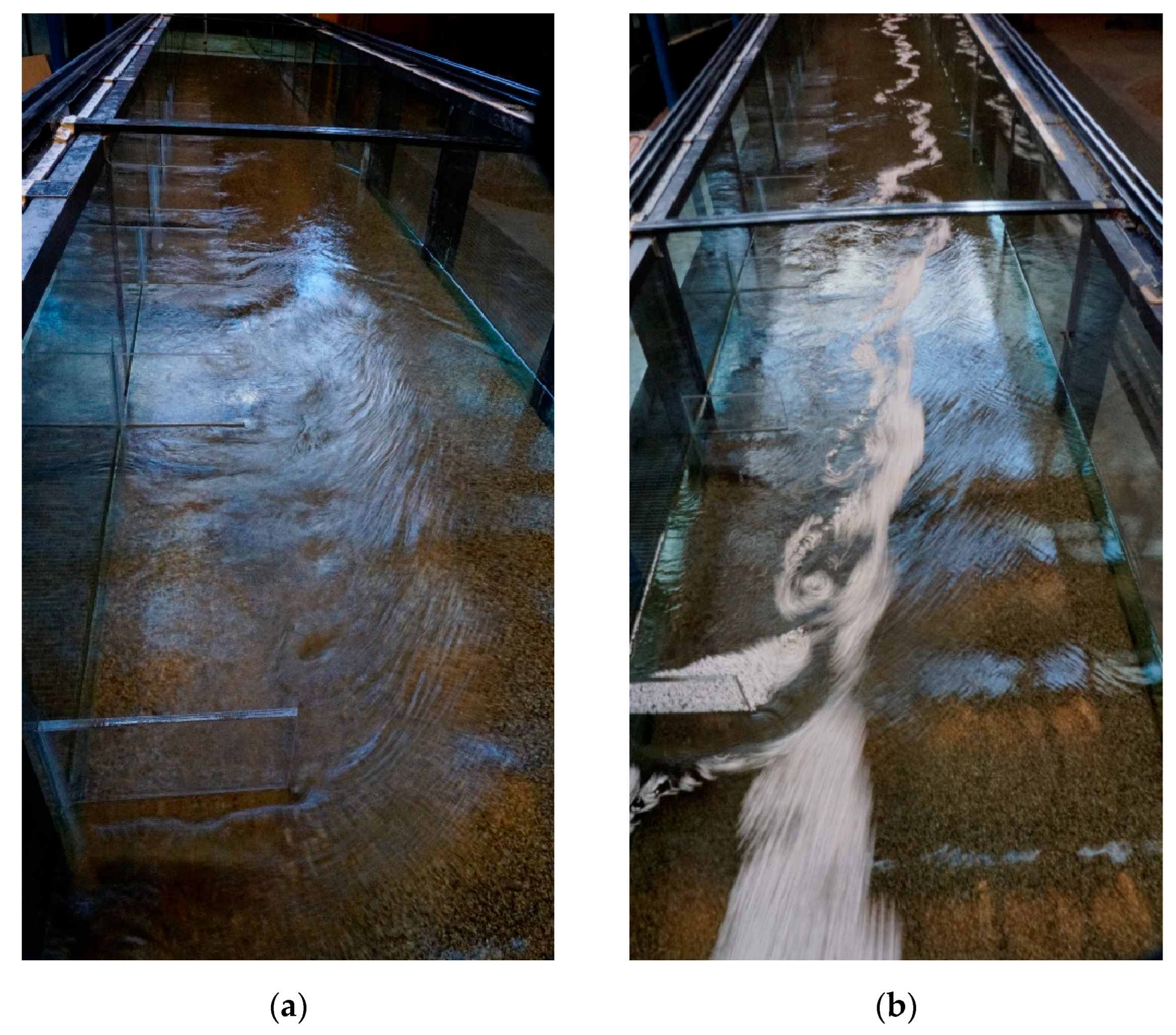
Figure 3 shows the water surface characteristics observed during runs CI-5 and CI-7. Interestingly, large vortices were generated after the collision of the approaching flow with the first spur dike, which developed primarily along the streamlines delimiting the recirculation zone (Figure 3a). Trials were conducted to capture their features by injecting small polystyrene spheres, as illustrated in Figure 3b.
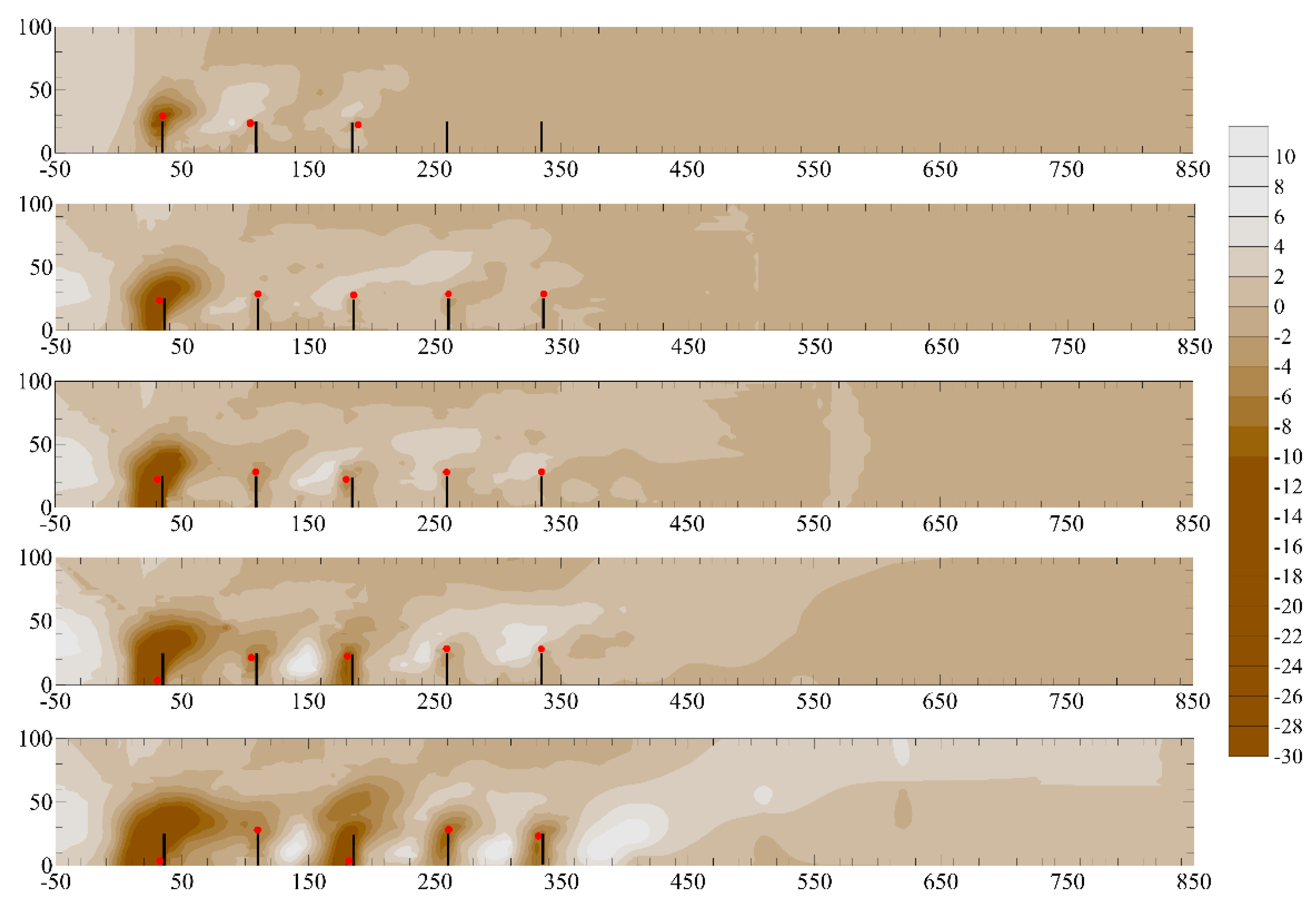
With reference to run CI-5, Figure 4 shows the contour maps of the surveyed bed morphology around the five spur dikes at 1.5, 23, 49, 72, and 145 h (from the start of the run). The main hydraulic and sedimentological conditions for this experiment were: discharge of 0.042 m3/s, approach flow depth of 0.158 m, and sand bed with a median grain size d50 of 1.7 mm and sediment gradation σ of 1.5. Notably, the local scour processes at various elements developed in an evident manner at different times. At 1.5 h, local scour developed primarily at the tip of the first spur dike, and the amount of removed sediment tended to propagate downstream, stopping only upstream of the second and third elements. Conversely, the bed levels around the fourth and fifth spur dikes, as well as further downstream, were undisturbed. After 23 h, the scour hole around the first spur dike was magnified, creating erosion on the part of the bank just upstream of the first spur dike itself. Interestingly, the removed sediments appeared almost uniformly distributed between the various spur dikes and, more generally, along the part of the channel in which the spur dikes were present. After 49 h, the bed morphology patterns became more complex; the local scour hole at the first spur dike tended to elongate toward the tip of the second spur dike. Sediment deposition tended to be concentrated immediately upstream of the third, fourth, and fifth elements, primarily around their tips. During this stage, some deposition occurred downstream of the spur dike. After 72 h, local scouring patterns were observed around the second and third spur dikes. However, local scour at the second spur dike appeared primarily because of the expansion of the scour hole at the first spur dike. Interestingly, the sediment deposition areas observed in the previous stage became more pronounced and leaned toward the bank. Finally, after 145 h, local scour and aggradation areas appeared well distinguished: local scour holes were evident around all five spur dikes. Similarly, aggradation zones were discernible along the right bank, and more between the second and third elements, between the third and fourth elements, between the fourth and fifth elements, and just downstream of the fifth element.
Figure 5 shows the contour plots of the bed morphological patterns observed around a single spur dike (run CI-1) and three (run CI-3), five (run CI-5), and seven (run CI-7) consecutive spur dikes for the approach flow conditions of Q = 0.042 m3/s and h0 = approximately 0.157 m.
Similar scour hole geometries around the first spur dike were observed in all runs with maximum scour depths (at the end of the runs), which were substantially constant, but strictly increased as the number of spur dikes increased (0.181, 0.184, 0.200, and 0.204 m for CI-1, CI-3, CI-5, and CI-7, respectively). These findings agree with the results of Kothyari et al. [25], who reported that spur dikes in cascade exacerbate approximately 10% of the maximum scour depth at a single spur dike. The scour hole shape of the first spur dike tended to stretch downstream when more spur dikes were added consecutively. This is probably because the local scour processes at the tip of the second spur, although limited, promoted the removal of sediments from the scour hole around the first spur dike. However, evidently, the second spur dike benefitted from the protective action of the first spur dike (the sacrificial spur dike). Therefore, this experimental study confirmed the findings of Ning et al. [15] that the scouring range of Spur Dike II is largely covered by the deposition of sediment flowing from Spur Dike I for a spacing of 3b. Moreover, moving from the setting with five spur dikes (run CI-5) to that with seven spur dikes (run CI-7), the fifth element involved in local scour processes in the case of run CI-5 was protected in the case of run CI-7, perhaps because of the more prolonged recirculation area. Regarding the aggradation areas, three distinct mounds of decreasing size moving downstream and interlaced with eroded areas were observed for a single spur dike. Essentially, the primary and secondary mounds reached the bank requiring protection, but also extended transversally to the channel axis. A similar condition occurred just downstream of the last spur dike in the case of the three spur dikes. As the number of spur dikes increased, the aggradation areas, although of a more modest size, tended to be confined between adjacent spur dikes, leaving the central region of the channel less disturbed.
Figure 4 and Figure 5 also show the position of the maximum scour depth at each spur dike. From the literature, it can be found that the maximum scour depth occurs at the head of the first spur dike. The experimental findings of this study revealed something different. In the case of the first spur dike, as in the case of the other spur dikes around which the local scour process was quite advanced, the position of the maximum scour depth tended to migrate from the spur dike head to the channel wall. This dynamic was also observed by Oliveto and Hager [13] for local scour processes at abutments.

4. Data Analysis and Results

The collected data were interpreted in light of the literature approaches. In particular, the empirical models proposed by Garde et al. [4], Gill et al. [7], and Pandey et al. [11], which apply to equilibrium conditions, were considered. The approaches of Inglis [3] and Ahmad [18] were disregarded because they assessed general rather than local scour phenomena. Subsequently, the temporal evolution of the maximum scour depth around various spur dikes was explored in a more complete manner based on the approach proposed by Oliveto and Hager [10]. The data processing is anticipated by the uncertainty analysis of measurement results.

4.1. Uncertainty and Statistical Analysis

In this study, the measurements made by the instruments for the experiments can be applied by the precision listed in Table 2 to take into account the uncertainties.
As already pointed out, the uncertainties due to the measurement of the discharge by the orifice plate were significantly reduced using the volumetric method with improved results. Moreover, the uncertainties associated with the time t of a survey were added to those listed in Table 2. The survey was completed within around 1 h at the earlier scour stage, while was completed within around 2 h in the later stages. Therefore, the time t associated with a given survey during the run was considered as the average time representative of the temporal interval in which the survey was completed.
A sensitivity analysis was carried out to identify the dominant dimensionless input of the proposed approach by Oliveto and Hager [10] on the local scour and access the influence of each input parameter on Z. The analysis was carried out using the mean values of each dimensionless input and output parameters from the experimental runs. An assumption was made that the errors in each input parameter were independent in the analysis. The average values of the dimensionless input parameters Fd and log(T) from the experiments in the study were 1.58 and 5.67, respectively.
If an error ΔY exists in the output, which can be defined as the difference between the output values computed for inputs X and X + ΔX, then the error can be estimated as the absolute sensitivity (AS = ΔY/ΔX). The output presented here is Y = Z and input X = Fd and log(T). The error can also be expressed as the relative error (RE = ΔY/Y) and as the relative sensitivity (RS = (X ΔY)/(Y ΔX)) [12]. The error ΔY is the deviation in input Y by the deviation ΔX being the error in input X. The sensitivity is investigated by ±10% in each input parameter and the results are recorded in Table 3. The results listed in Table 3 specify that Fd is the most sensitive input parameters among them. The relative sensitivity of Fd is 1.47 for log(T) in 10% increment in X and 1.54 in 10% decrement in X, respectively. Therefore, the computing accuracy of the proposed approach by Oliveto and Hager [10] greatly depends on Fd. Thus, the dimensionless scour depth Z at the first spur dike is significantly dependent on the densimetric Froude number, Fd.
The proposed approach by Oliveto and Hager [10] was examined using several statistical indices. These indices can be applied to evaluate the agreement of the predicted and experimental values of Z. The following statistical indices can be defined as coefficient of correlation (CC), mean absolute error (MAE), mean square error (MSE), root mean square error (RMSE), and mean absolute percentage error (MAPE), as follows:
C C = N X X ˊ X X ˊ n X 2 ( X ) 2   n X ˊ 2 ( X ˊ ) 2
M A E = 1 N i = 1 N | X i X ˊ i |
M S E = 1 N i = 1 N ( X i X ˊ i ) 2
R M S E = i = 1 N ( X i X ˊ i ) 2 N
M A P E = 100 N i = 1 N | X i X ˊ i | | X i |
where X is the observed value of Z from the experiment, X′ is the corresponding predicted value of Z, and N represents the number of experimental runs. The statistical values of CC, MAE, MSE, RMSE, and MAPE are 0.91, 0.085, 0.0097, 0.099, and 9.9, respectively. Overall, the prediction using the approach of Oliveto and Hager [10] is agreeable.

4.2. Comparison of the Experimental Data to Literature Formulas for Scour at the Equilibrium Stage

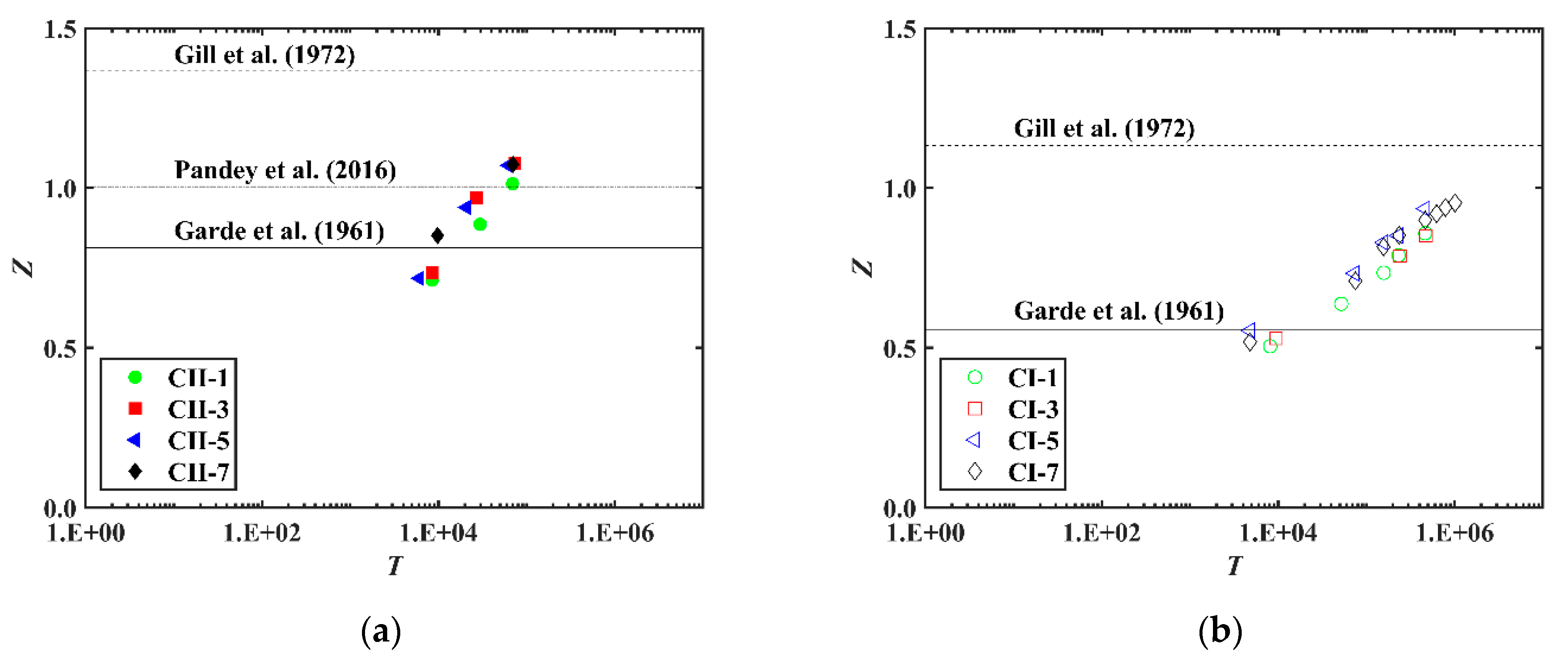
Figure 6 shows the collected data plotted on the plane Z, T according to the dimensionless variables introduced by Oliveto and Hager [10]. This highlights the limitations of the formulas under consideration when increasing the duration of the tests. In Figure 6a, the data for runs CII-1, CII-3, CII-5, and CII-7 are compared with the predictions (independent of time) from Equations (2), (3), and (6). In Figure 6b, the data for runs CI-1, CI-3, CI-5, and CI-7 are compared with the predictions from Equations (2) and (3) only, because Equation (6) does not apply for V/Vc less than 0.5, as in the present study.

4.3. Temporal Evolution of Scour Depth

The collected experimental data were compared with the predictive model proposed by Oliveto and Hager [10] to account for the effect of the time. In this case, the experimental data points were plotted on the plane 0.5/Fd1.5, T according to the dimensionless variables introduced by Oliveto and Hager [10]. The reason for the use of this plane is behind the structure of Equation (5). In fact, when a semi-logarithmic plot is used with the time T on the x-axis and the y-axis on a linear scale, the experimental datapoints should collapse on a single line independently of Fd and σ. Figure 7a shows the temporal scour evolution around the first spur dike, and Figure 7b extends the data analysis to the local scour around the other spur dikes. The predictions according to Oliveto and Hager [10] are represented by the straight line with ±25% prediction-bands error, as suggested by the authors.

5. Discussion

As shown in Figure 6a, the scour depth predictions of Pandey et al. [11] are underestimated and only the experimental data collected at the earlier scour stages are better simulated. Moreover, the approach by Garde et al. [5] fails for dimensionless times T greater than 5 × 10⁴, instead presenting an underestimation. Conversely, the formula by Gill [7] is more conservative, but underperforms in the case of floods of limited duration.
Figure 7a reveals that the temporal scour evolution around the first spur dike followed a logarithmic trend, with the values within the +25% prediction-band error. Further, in the case of spur dikes in cascade, the scour processes around the first spur dike underwent an increase, albeit to a limited extent. This finding was consistent with the approach proposed by Kothyari et al. [25] for multiple spur dikes. Figure 7b provides insight into the spur dikes beyond the first dike. Notably, the second spur dike was protected by the first. Scour depths, although slightly increasing over time, were significantly lower than those at the first spur dike, thus highlighting the sacrificial role of the first spur dike. For the third, fourth, and fifth spur dikes the scour processes were delayed and started at a dimensionless time T greater than approximately 103. However, the scour rates increased to a high degree, with the scour depths tending to match the observed values at the first spur dike. Finally, the scour depths at the fifth, sixth, and seventh dikes were found to be approximately zero, with fluctuating trends owing to aggradation effects from upstream. Only these elements can be considered as effectively protected from upstream elements.
Some comments on how the results of the present study can be generalised are given below. The results of this study are primarily provided in terms of the temporal trend for the maximum scour depth at the first spur dike (where typically scour depths are higher). Interestingly, a similar approach can be used to identify the temporal trend of the maximum scour depth at the other spur dikes when spur dikes in cascade are considered. However, more experimental data are needed for this purpose. Moreover, the scour equation proposed in this study can be used to predict the maximum scour depth at the first spur dike under unsteady flows, using an approach similar to that proposed by Oliveto and Hager [10] in the case of bridge piers. With regard to the spur dike spacing, preliminary experimental observations revealed that this parameter does not play an important role in the scouring processes at the first spur dike. Conversely, significant effects can occur at the second spur dike and might occur at the other spur dikes. As noted in the Introduction section, in the case of a group of four spur dikes with a spacing of 4b, the shielding effect of Spur Dike I would only partially affect a section of Spur Dike II [15]. The local scour morphology of each spur dike would remain relatively complete, forming four largely independent scour holes. However, the study by Gu et al. [17] indicates a larger spacing for a complete damping of the shadowing effect. At a spacing of 16b, the length of the downstream backflow zone at Spur Dike I was less than the spacing, and the influence of Spur Dike I on Spur Dike II decreased. At a spacing of 30b, the spacing was much larger than the length of the downstream backflow zone at spur dike I. The flow patterns near the two spur dikes were very similar, which indicates that the interaction between them had disappeared in general.

6. Conclusions

Selected experiments were performed for up to 13 days at the University of Basilicata, Italy, in a rectangular channel (20 m long and 1 m wide) to explore the temporal and spatial patterns of bed morphological changes around single and multiple spur dikes in clear-water flows. The main results can be summarised as follows.
-
Some limitations of the formulas for the equilibrium scour depth at the first spur dike reported in the literature were emphasised. Underestimations (i.e., the ratio between the actual and predicted values) up to 160% and overestimation (i.e., the ratio between the predicted and actual values) up to 200% at the earlier scour stages were found.
-
The temporal evolution of scour depth at the first spur dike was satisfactorily predicted with a coefficient of correlation (CC), mean absolute error (MAE), and mean square error (MSE) of 0.91, 0.085, and 0.0097, respectively.
-
Similar scour hole geometries around the first spur dike were observed in all runs, with the maximum scour depth (at the end of each run) remaining almost unchanged, but strictly increasing as the number of spur dikes increased.
-
The scour depths on the second spur dike, although slightly increasing over time, were significantly lower than those at the first spur dike. Therefore, this experimental study confirmed some literature findings that also found that the scouring range at the second spur dike is largely covered by the deposition of sediment flowing from the first spur dike for a spacing of 3b.
-
For the third, fourth, and fifth spur dikes, the scour processes were delayed and started at a dimensionless time T greater than approximately 103. However, the scour rates increased to a high degree, with scour depths tending to match the observed values at the first spur dike. In the case of the first spur dike, as in the case of the other spur dikes around which the local scour process was quite advanced, the position of the maximum scour depth migrated from the spur dike head to the channel wall.
-
The scour depths at the fifth, sixth, and seventh spur dikes were found to be approximately zero; therefore, only these elements could be considered effectively protected from the upstream ones.
-
Three distinct mounds of decreasing size, moving downstream, and interlaced by eroded areas were observed for a single spur dike. The primary and secondary mounds reached the bank, requiring protection, and extended transversally to the channel axis. As the number of spur dikes increased, the aggradation areas, although of a more modest size, tended to be confined between adjacent dikes, leaving the central region of the channel less disturbed.
Finally, it would appear that the approaches used in this study can be upscaled to real contexts because they are based on coherent dimensionless parameters and experiments most likely free of scale effects. Moreover, the results of this study can be beneficial for assessing the performance of numerical models. Conversely, an extension of the present experimental work can also target the characterisation of bed morphological patterns when sediment transport occurs along the upstream approaching reach.

Author Contributions

Conceptualisation, H.A., B.O., G.O. and G.Y.; methodology, H.A., B.O., G.O. and G.Y.; software, H.A.; validation, H.A., B.O., G.O. and G.Y.; formal analysis, H.A., B.O., G.O. and G.Y.; investigation, H.A., B.O., G.O. and G.Y.; resources, H.A., B.O., G.O. and G.Y.; data curation, H.A.; writing—original draft preparation, H.A., B.O., G.O. and G.Y.; writing—review and editing, H.A., B.O., G.O. and G.Y.; visualisation, H.A. and G.O.; supervision, H.A., B.O., G.O. and G.Y.; project administration, H.A., G.O. and G.Y.; funding acquisition, G.O. and G.Y. All authors have read and agreed to the published version of the manuscript.

Funding

This research was partially funded by the National Natural Science Foundation of China (No. 52171268) and CCCC Road & Bridge Special Engineering Co., Ltd.

Data Availability Statement

The data of this study will be made available through the PhD thesis by the first author.

Conflicts of Interest

The authors declare no conflict of interest.

References

  1. Barkdoll, B.D.; Ettema, R.; Melville, B.W. Countermeasures to Protect Bridge Abutments from Scour; NCHRP Report 587; Transportation Research Board: Washington, DC, USA, 2007; pp. 38–41. [Google Scholar]
  2. Copeland, R.R. Bank Protection Techniques Using Spur Dikes; Miscellaneous Paper HL-83-1; National Information Service: Springfield, VA, USA, 1983; pp. 7–12. [Google Scholar]
  3. Inglis, C.C. The Behaviour and Control of Rivers and Canals; Yeravda Prison Press: Poona, India, 1941; pp. 327–348. [Google Scholar]
  4. Garde, R.J.; Subramanya, K.; Nambudripad, K.D. Study of scour around spur-dikes. J. Hydraul. Div. ASCE 1961, 87, 23–37. [Google Scholar] [CrossRef]
  5. Garde, R.J.; Subramanya, K.; Nambudripad, K.D. Scour around obstructions. Irrig. Power 1961, 18, 651–660. [Google Scholar]
  6. Cunha, L.V. Time evolution of local scour. In Proceedings of the 12th IAHR Congress, Fort Collins, CO, USA, 11–14 September 1967. [Google Scholar]
  7. Gill, M.A. Erosion of sand beds around spur dikes. J. Hydraul. Div. ASCE 1972, 98, 1587–1602. [Google Scholar] [CrossRef]
  8. Kothyari, U.C.; Ranga Raju, K.G. Scour around spur dikes and bridge abutments. J. Hydraul. Res. 2001, 39, 367–374. [Google Scholar] [CrossRef]
  9. Kuhnle, R.A.; Alonso, C.V.; Shields, F.D., Jr. Local scour associated with angled spur dikes. J. Hydraul. Eng. ASCE 2002, 128, 1087–1093. [Google Scholar] [CrossRef]
  10. Oliveto, G.; Hager, W.H. Further results to time-dependent local scour at bridge elements. J. Hydraul. Eng. ASCE 2005, 131, 97–105. [Google Scholar] [CrossRef]
  11. Pandey, M.; Ahmad, Z.; Sharma, P.K. Estimation of maximum scour depth near a spur dike. Can. J. Civ. Eng. 2016, 43, 270–278. [Google Scholar] [CrossRef]
  12. Pandey, M.; Valyrakis, M.; Qi, M.; Sharma, A. Experimental assessment and prediction of temporal scour depth around a spur dike. Int. J. Sediment Res. 2021, 36, 17–28. [Google Scholar] [CrossRef]
  13. Oliveto, G.; Hager, W.H. Temporal evolution of clear-water pier and abutment scour. J. Hydraul. Eng. ASCE 2002, 128, 811–820. [Google Scholar] [CrossRef]
  14. Gu, Z.; Cao, X.; Jiao, Y.; Lu, W.-Z. Appropriate CFD models for simulating flow around spur dike group along urban riverways. Water Reour. Manage. 2016, 30, 4559–4570. [Google Scholar] [CrossRef]
  15. Ning, J.; Li, G.; Li, S. Numerical simulation of the influence of spur dikes spacing on local scour and flow. Appl. Sci. 2019, 9, 2306. [Google Scholar] [CrossRef]
  16. Han, X.; Lin, P.; Parker, G. Influence of layout angles on river flow and local scour in grouped spur dikes field. J. Hydrol. 2022, 614, 128502. [Google Scholar] [CrossRef]
  17. Gu, Z.; Cao, X.; Cao, M.; Lu, W. Integrative study on flow characteristics and impact of non-submerged double spur dikes on the river systems. Int. J. Environ. Res. Public Health 2023, 20, 4262. [Google Scholar] [CrossRef] [PubMed]
  18. Ahmad, M. Experiments on design and behavior of spur dikes. In Proceedings of the 5th IAHR Congress, Minneapolis, MN, USA, 1–4 September 1953. [Google Scholar]
  19. Dey, S.; Barbhuiya, A.K. Time variation of scour at abutments. J. Hydraul. Eng. ASCE 2005, 131, 11–23. [Google Scholar] [CrossRef]
  20. Gisonni, C.; Hager, W.H. Spur failure in river engineering. J. Hydraul. Eng. ASCE 2008, 134, 135–145. [Google Scholar] [CrossRef]
  21. Oliveto, G.; Marino, M.C. Temporal scour evolution at non-uniform bridge piers. Water Manag. 2017, 170, 254–261. [Google Scholar] [CrossRef]
  22. Dey, S.; Raikar, R.V. Scour in long contractions. J. Hydraul. Eng. ASCE 2005, 131, 1036–1049. [Google Scholar] [CrossRef]
  23. Graf, W.H.; Altinakar, M.S. Fluvial Hydraulics-Flow and Transport Processes in Channels of Simple Geometry; John Wiley & Sons Inc: Chichester, UK, 1998; pp. 10–12. [Google Scholar]
  24. Chiew, Y.M.; Melville, B.W. Local scour around bridge piers. J. Hydraul. Res. 1987, 25, 15–26. [Google Scholar] [CrossRef]
  25. Kothyari, U.C.; Hager, W.H.; Oliveto, G. Generalized approach for clear-water scour at bridge foundation elements. J. Hydraul. Eng. ASCE 2007, 133, 1229–1240. [Google Scholar] [CrossRef]
Figure 1. Channel cross section at spur dike location (scheme on the left) and spacing for spur dikes in cascade (scheme on the right).
Water 15 01746 g001
Figure 2. Vertical velocity profiles at the approaching section 1 m upstream from the first spur dike for runs C-I 1 (diagram on the left) and C-II 1 (diagram on the right). Transverse sections (●) at the centre line, (+) at a distance of 0.25 m from the channel wall where the spur dike is fixed, and (✕) at a distance of 0.75 m from the same channel wall.
Water 15 01746 g002
Figure 3. Flow patterns during the run CI-5 (a) and vortices visualisation using small spheres of polystyrene as tracers during CI-7 (b). The spheres of polystyrene had a diameter of about 4 mm and they were buoyant. Therefore, they described surface flow structures and attempted establishing a connection to the bed surface effects.
Water 15 01746 g003
Figure 4. Contour maps, from top to bottom, at 1.5, 23, 49, 72, and 145 h of the observed morphological bed patterns for run CI-5. Dimensions are in cm. The red dot indicates the position of the maximum scour depth at each spur dike.
Water 15 01746 g004
Figure 5. Contour maps at 145 h for the bed morphology of runs, from top to bottom, CI-1, CI-3, CI-5, and CI-7. Dimensions are in cm. The red dot indicates the position of the maximum scour depth at each spur dike.
Water 15 01746 g005
Figure 6. Comparison between the experimental data collected in the present study and Equation (2) from Garde et al. [4], Equation (3) from Gill [7], and Equation (6) from Pandey et al. [11]. (a) Runs CII-1, CII-3, CII-5, and CII-7; (b) runs CI-1, CI-3, CI-5, and CI-7.
Water 15 01746 g006
Figure 7. Experimental data points (a) for the first spur dike (symbols and colours are the same as those used in Figure 6) and (b) for all spur dikes in the case of run CI-7.
Water 15 01746 g007
Table 1. Summary of the main test conditions. Regarding the label associated with each run, “CI” refers to the runs with Q = 0.042 m3/s (and Fd = 1.62 on average), “CII” to the runs with Q = 0.075 m3/s (and Fd = 1.96 on average), and “No.” refers to the number of dikes.
RunNo. of DikesQ
(m3/s)
h0
(m)
Fd
(-)
Fdi
(-)
t (hrs)Re·105
(-)
CII-110.0750.2262.0003.565251.812
CII-330.0750.2252.0073.564261.814
CII-550.0750.2361.9163.582261.788
CII-770.0750.2341.9323.569251.793
CI-110.0420.1501.6883.3911441.134
CI-330.0420.1621.5633.4251501.113
CI-550.0420.1581.6023.4141451.120
CI-770.0420.1571.6133.4113181.122
Table 2. Precision for instruments used in the experiments.
InstrumentsNo. of Dikes
Point gauge±1 mm
Shoe gauge±2 mm
Low-speed probe±1.5% true velocity
Orifice plate±5%
Table 3. Sensitivity analysis for the approach by Oliveto and Hager [10].
Percentage of ChangeXΔXΔYASRSRE
+10% increaseFd0.1580.1200.7591.3320.133
log(T)0.5670.0780.1380.9090.091
−10% increaseFd0.158−0.114−0.723−1.712−0.171
log(T)0.567−0.078−0.138−1.111−0.111
Disclaimer/Publisher’s Note: The statements, opinions and data contained in all publications are solely those of the individual author(s) and contributor(s) and not of MDPI and/or the editor(s). MDPI and/or the editor(s) disclaim responsibility for any injury to people or property resulting from any ideas, methods, instructions or products referred to in the content.