Article

A Three-Dimensional Fully-Coupled Fluid-Structure Model for Tsunami Loading on Coastal Bridges

by
Dilshan S. P. Amarasinghe Baragamage
1,2 and
Weiming Wu
2,*
1
Department of Mechanical Engineering, University of Moratuwa, Bandaranayake Mawatha, Moratuwa 10400, Sri Lanka
2
Department of Civil and Environmental Engineering, Clarkson University, Potsdam, NY 13699, USA
*
Author to whom correspondence should be addressed.
Water 2024, 16(1), 189; https://doi.org/10.3390/w16010189
Submission received: 29 October 2023 / Revised: 17 December 2023 / Accepted: 30 December 2023 / Published: 4 January 2024
(This article belongs to the Special Issue Estuarine and Coastal Hydrodynamics)

Abstract

:
A three-dimensional (3D) fully-coupled fluid-structure model has been developed in this study to calculate the impact force of tsunamis on a flexible structure considering fluid-structure interactions. The propagation of a tsunami is simulated by solving the 3D Navier–Stokes equations using a finite volume method with the volume-of-fluid technique. The structure motion under the tsunami impact force is simulated by solving the motion equation using the generalized alpha method. The structure motion is fed back into the fluid solver via a technique that combines a sharp-interface immersed boundary method with the cut-cell method. The flow model predicts accurate impact forces of dam-break flows on rigid blocks in three experimental cases. The fully coupled 3D flow-structure model is tested with experiments on a large-scale (1:5) model bridge under nonbreaking and breaking solitary waves. The simulated wave propagation and structure restoring forces generally agree well with the measured data. Then, the fully-coupled fluid-structure model is compared with an uncoupled model and applied to assess the effect of flexibility on structure responses to tsunami loading, showing that the restoring force highly depends on the dynamic characteristics of the structure and the feedback coupling between fluid and structure. The maximum hydrodynamic and restoring forces decrease with increasing structure flexibility.

1. Introduction

About 10 percent of the global population live in coastal areas that are less than 10 m above sea level [1] and susceptible to natural disasters, such as tsunamis and storm surges. Recent examples include the 2004 Indian Ocean tsunami, 2010 Chilean tsunami, and 2011 East Japan tsunami, which caused many casualties and tremendous damage to the impacted areas [2,3,4]. As a tsunami approaches the shoreline, its dynamics are significantly affected by the local shoreline topography [5]. It may break up and become highly turbulent, then run up the shoreface and hit coastal structures [6]. Its loading on the structures depends on the features of the flow and structures. The underlying physics of fluid-structure interactions are little understood and plagued with uncertainties.
It is very challenging to carry out proper field experiments of tsunamis due to their destructive nature. Therefore, laboratory experiments using scaled models have been carried out to find insights into the underlying physics and develop the current state of knowledge. The experiments include run-up, pressure, and force measurements. Most of the past experiments modeled the tsunami inundation as a two-dimensional (2D) flow, and some of the recent experiments have given priority to the three-dimensional (3D) nature of the flow field, as summarized by St-Germain [7], Al-Faesly [8], and Istrati [9]. These experiments used dam-break flows [10,11,12,13,14,15] and solitary waves [9,16,17,18] to approximate tsunamis.
Another methodology to investigate tsunami wave propagation and its impact is numerical modeling. Numerical models are usually based on two approaches: Eulerian and Lagrangian. The Lagrangian approach has gained popularity due to several reasons: (1) it is meshless, (2) no special techniques are required for water-air interface tracking, and (3) it has excellent conservation property. Out of the meshless techniques, the smoothed particle hydrodynamics (SPH) has found wider acceptance. SPH was first introduced to simulate astrophysical processes [19] and then adapted to hydrodynamics in the 1990s [20]. St-Germain et al. [21] used a serial version of SPH to calculate tsunami-induced loading on a square block and validated the simulations with experimental data from Al-Faesly et al. [10]. Wei et al. [22] used a GPU-based SPH model to investigate the force measured by Arnason [11]. They noted that the gate opening in a dam-break flow plays a significant role in the development of the hydraulic bore. Furthermore, Wei and Dalrymple [23] used the same SPH model to investigate the tsunami force on a bridge superstructure and analyzed the performance of tsunami mitigation by a service road bridge and an offshore breakwater. They observed that the service road and offshore breakwaters are effective in reducing the force on the main bridge.
The Eulerian approach divides the flow domain into a number of small elements called cells, a collection of which is referred to as a mesh. It requires special techniques to define the evolution of a free surface when solving Navier–Stokes equations. The often-used techniques include marker-and-cell, volume-of-fluid (VOF), and level set methods. The VOF method has found wider acceptance over other techniques due to its simplicity, lower memory consumption, and performance. Since its initial implementation by Hirt and Nichols [24], VOF has branched into a multitude of different schemes over the past decades.
Hayatdavoodi et al. [17] carried out experimental and numerical investigations of a two-lane coastal bridge subjected to tsunami-induced loading. They used the inviscid flow model (Euler’s equations) along with the VOF to model the flow field numerically. They examined the effect of the skew angle of the bridge on the wave loading. Bricker and Nakayama [25] used the VOF-based interFOAM® solver to analyze the failure of the Utatsu highway bridge in Minamisanriku due to the 2011 East Japan Tsunami. They found that the trapped air between the girders, bridge inclination, and presence of a nearby seawall had contributed to the bridge failure. Sarjamee et al. [26] and Asadollahi et al. [27] also investigated the influences of turbulence models and drag coefficient on the tsunami loading.
Until recently, almost all the physical experiments and numerical models related to tsunami-induced forces considered only rigid structures and ignored the dynamic responses of the structures. However, the dynamic responses of the structures and the interactions with the surrounding flow field may not be negligible as the structures become flexible. Recently a few studies have started to consider structural dynamics. For example, Istrati and Buckle [28] used a commercially available multiphysics code to simulate the fluid-structure dynamic interactions for a bridge superstructure model. They found that the flexibility of the bridge significantly alters the induced tsunami loading as well as the bridge connection forces. Though their numerical results were not validated with experimental data, their works demonstrated the importance of considering the dynamic response of structures subjected to extreme hydrodynamic loading and opened a discussion for further research on understanding the underlying complex physics. On the other side, Abraham [29] used dam-break experiments to study the interaction of a flexible plate subjected to extreme wave impact loading, and Istrati [9] carried out experiments to analyze the fluid-structure interactions of tsunami waves on large-scale (1:5) bridge models. The experimental results suggest that the dynamic response of structures affects the reaction forces in the structures.
Considering structural responses to the hydrodynamic loading significantly complicates the computation process of tsunami dynamics. Various approaches exist to addressing such fluid-structure interaction (FSI) problems, including boundary-conforming dynamic mesh, Arbitrary Lagrangian–Eulerian (ALE) [30], meshless, immerse-boundary (IB) [31], cut-cell [32], and machine learning methods [33,34]. While boundary-conforming mesh, ALE, and meshless methods, like SPH, introduce additional computational overheads, IB-based methods offer a simpler means of incorporating structural motion into the fluid domain [35]. It is noteworthy that OpenFOAM, an open-source toolkit, provides various FSI solvers, such as ALE-based fsiFoam [36] and solids4Foam [37]. A comprehensive review on wave-structure interaction using OpenFOAM can be found in Huang et al. [38].
The present study has attempted to develop a coupled fluid-structure model to capture the local fluid-structure interactions during tsunami impacts. The effort involves identifying and implementing computationally efficient techniques to solve the 3D Navier–Stokes equations for tsunami propagation, model the structural dynamics, and integrate the structural solver into the fluid model. The developed model is validated using experimental data and then applied to explore how the structural dynamics affect the fluid-structure interactions.

2. Flow Model

2.1. Governing Equations

The bore front of a tsunami wave is highly turbulent and three-dimensional and exhibits the nature of a shock wave. Therefore, a 3D flow model based on the Navier–Stokes equations is preferred to capture the flow dynamics. The governing equations of water flow are written as follows based on the conservation of mass and momentum:
u = 0
t ρ u + ρ u u = p + ρ g + μ u + F σ
where t = time; u = flow velocity vector; p = pressure; ρ = water density; g = gravitational acceleration vector; F σ = other external forces; μ = dynamic viscosity due to molecular motion and turbulence; = cross product of vectors; and = i / x + j / y + k / z , with x, y, and z = spatial coordinates.
The governing equations are discretized by employing the finite volume method (FVM). The study domain is divided into a suitable number of hexahedral control volumes (cells) shown in Figure 1a. The numerical discretization and solution procedure are described in the following sections.

2.2. Free-Surface Capturing Using the Weller-VOF Technique

There are a variety of VOF schemes in the literature to capture the hydraulic bore propagation. These schemes can be grouped into two classes: (1) geometric and (2) algebraic [39]. In geometric methods, the sub-cell representation of the volume fraction is explicitly reconstructed with geometric means. In algebraic techniques, an algebraic function is manipulated to represent fluid interfaces. The geometric techniques have less numerical diffusion and thus provide sharper fluid interfaces. However, they are relatively difficult to implement in three dimensions and have an increased computational requirement [40]. Furthermore, they are also difficult to use with features in modern computer architectures, such as the SIMD (Single Instruction Multiple Data) and AVE (Advanced Vector Extensions) instruction sets. On the other hand, the algebraic methods are simple to implement, require less computation, and are easy to parallelize. However, algebraic methods show more numerical diffusion than geometric methods [39].
For the present 3D model, the algebraic VOF method used in the interFOAM solver [41] is selected by balancing the computation effort, ease of parallelization, and accuracy. The interFOAM solver is one of the multiphase solvers implemented in the OpenFOAM CFD toolkit. It has been repeatedly tested and validated by the active OpenFOAM research community around the globe. Particularly, the Weller-VOF scheme [39,42] is used in the present model. It simulates the time evolution of the water-air interface by solving the following transport equation of water volume fraction ( ψ ):
ψ t + ψ u + ψ 1 ψ u r = 0
where u r = relative velocity between water and air, also referred to as an artificial compressive velocity. The standard VOF schemes use Equation (3) without the third term, which becomes insignificant in the domain away from the fluid interfaces.
Integrating Equation (3) in the control volume, using the divergence theorem to simplify the expressions, and using the Euler scheme for the temporal derivative yields
ψ P n + ν + 1 ψ P n + ν Δ t V P + f ψ f n + ν F f N , n + ν + f ψ n + ν 1 ψ n + ν f   F r , f N L , n + ν = 0
where V P = control volume size; Δ t = time step; F N = volumetric flux from the mixture velocity; F r N L = volumetric flux from the artificial interference compression velocity; subscript P = current cell center; subscript f = cell face; and ν = iteration step number.
The face values ψ f and ψ n + ν 1 ψ n + ν f are calculated using a blended scheme (BS) [43]. In this method, the face values are calculated by averaging a lower-order scheme and a higher-order one:
ψ f = ω ψ f L + 1 ω ψ f H
where ω = weighting coefficient computed by a suitable limiter function.
For the subsequent numerical tests, the first-order upwind scheme is selected for ψ f L , and the second-order central difference scheme is used for ψ f H . Furthermore, the van Leer limiter [44] is used in the ψ f face value calculation, whereas the following interfaceCompression limiter is used for the ψ n + ν 1 ψ n + ν f term:
ω = min max 1 max 1 4 ψ P ( 1 ψ P ) 2 , 1 4 ψ N ( 1 ψ N ) 2 , 0 , 1
where N = neighboring cell of the face f.
Moreover, the artificial compressive flux term in Equation (4) is modeled with
F r N L , n = C α ϕ f n Δ S f n Δ S f
where C α = interface compression coefficient, set as 1.0 as suggested by Deshpande et al. [39]; n = interface unit normal vector (Figure 1); ϕ f n = volumetric flux calculated at the previous time step; Δ S f = outward area vector of the cell face f; ∣ ∣ = absolute value; and ∥ ∥ = Euclidean norm of a vector.
Equation (4) is solved by using the flux-corrected transport technique [45,46]. More details of the solution algorithm for calculating the volume fraction field can be found in Damián [47].

2.3. Solution of Momentum Equations

The momentum equation is slightly modified to simplify the solution process and handle sharp density differences at the interface [48]:
t ρ m u + ρ m u u = p + μ m u + u μ m g x ρ m + F σ
where ρ m and μ m = density and viscosity of the water-air mixture, respectively, and p = p ρ m g x .
Integrating Equation (8) over the control volume and using the Euler scheme for the temporal derivative yields
ρ m n + 1 u n + 1 P ρ m n u n P Δ t V P + f m ˙ f u f n + 1 = f μ m , f u N n + 1 u P n + 1 Δ S f d P N + p P , n + 1 + u P n μ m , P n + 1 g x P ρ m , P n + 1 + F σ , P V P
where d P N = position vector from the current cell to the neighboring cell N (Figure 1b), and m ˙ f = mass flux at cell face f:
m ˙ f = ρ m u f Δ S f + ψ ( 1 ψ ) ρ ρ a i r u r f Δ S f
F σ includes additional external forces exerted on the control volume. In the present study, the only additional external force is the surface tension acting at the fluid interface. However, this force is insignificant in the turbulent flow regime, which governs the tsunami hydraulic bores. Nonetheless, the method of Brackbill et al. [49] is used for modeling the surface tension as
F σ = σ κ ψ
where σ = constant (0.07 used), and κ = the interface curvature calculated with κ = ψ / ψ .
In the discretized momentum equation, the cell face velocity u f is calculated using the first-order upwind scheme. The mass flux term is kept constant over the time step to linearize the equation. For convenience, the discretized momentum equation is written as
A P u P = P N A N u N p + S P
where P N = over all neighboring cells of the current cell P; S P = source term lumping the remaining explicit terms; A N = coefficient corresponding to the neighboring cell N; and A P = sum of coefficients from all the neighboring cells. The pressure gradient term is treated explicitly. This step is often referred to as the momentum predictor step.

2.4. Pressure-Velocity Coupling

The continuity equation is discretized as
C V u d V = C S u f d S = f u f Δ S f = 0
Because there is no governing equation dedicated for the pressure, the above continuity equation is used to derive the pressure equation. Two approaches are often used to arrange the grid system. One is the collocated grid, where pressure and velocities are stored at cell centers. The other approach is the staggered grid, where pressure is stored at cell centers and velocities are stored at cell faces. A checker-board oscillation likely exists in the collocated grid because the pressure of the current cell is decoupled from the discretized pressure equation [50,51]. This adverse oscillation can be eliminated by using the momentum interpolation technique of Rhie and Chow [52], or by using the staggered grid [50]. The staggered grid is cumbersome to implement and limits the shape of the cells used. Therefore, the collocated grid is used in this study. Following Rhie and Chow [52], the velocity at cell face f is obtained as follows by interpolating the momentum equation defined in Equation (12) based on the distance from cell center to face center (Figure 1b):
u f = H ( u N ) A P f 1 A P p f
where H ( u N ) = P N A N u N + S P given in Equation (12), p / A P f 1 / A P f p f , H ( u N ) / A P f = f P H / A P P + ( 1 f P ) H / A P N , 1 / A P f = f P 1 / A P P + ( 1 f P ) 1 / A P N , and f P = interpolation weight factor calculated with f P = d f N / d f N + d f P .
Substituting Equation (14) into Equation (13) and using p f Δ S f = p N p P Δ S f / d P N yields
a P p P + P N a N p N = f H ( u N ) A P f Δ S f
where a N = 1 / A P f Δ S f / d P N , and a P = f a N .
Equation (15) is often referred to as the pressure Poisson equation, which generates a symmetric, diagonally dominant matrix. It is solved using the conjugate gradient (CG) method. The CG solver is an efficient sparse matrix solver and require minimal resource compared to general matrix solvers.
Once pressure is calculated, the cell center velocity is updated as
u P = H A P + 1 A P f n f Δ S f 1 f σ κ f l x ρ f l x p f l x 1 / ( A P ) f n f
where σ κ f l x = σ κ f ψ f Δ S f , ρ f l x = ( g x ) f ( ρ ) f Δ S f , p f l x = ( p ) f Δ S f , and n f = unit vector normal to the face f.
The PISO (Pressure-Implicit with Splitting of Operators) algorithm [53] is used for updating and coupling pressure and velocity fields. PISO is different from other iterative techniques in the SIMPLE algorithm class. The solution process starts with solving the volume fraction transport equation. The mass flux and density terms are calculated at this step. Then the discrete momentum equations are solved with updated mass flux using pressure from the previous iteration. Finally, the predicted velocity field is used to calculate the new pressure field. PISO applies a finite number of iterations (usually two or three) and assumes that the pressure and velocities are converged, then moves to the next time step solution.
Note that all the previous derivations of the discrete equations are based on an orthogonal mesh where the position vector d P N is parallel to the area vector Δ S f . Unfortunately, for real-world complex geometries, it is not always possible to generate orthogonal meshes. The grid nonorthogonality is addressed in the current model by using the over-relaxation method proposed by Jasak [54]. The area vector is divided into two components: one maintaining orthogonality to the face and the remaining nonorthogonal vector. The orthogonal component is treated implicitly and the nonorthogonal component is treated explicitly and arranged into the source term during the iteration or time marching process.

2.5. Turbulence Closure

The sub-grid turbulence model of Smagorinsky [55] is used to calculate the eddy viscosity. This model does not require the solution of a system of equations and has shown adequate accuracy for the current applications. It calculates the viscosity as
μ = μ 0 + ρ C S 2 Δ 2 2 i j T i j 2
where μ 0 = dynamic viscosity due to molecular motion, Δ = V P 1 / 3 , T = [ u + ( u ) T ] / 2 , and C S = calibration coefficient. The coefficient C S can range between 0.1 and 0.25. It is found that a value of 0.1 gives the best results in this study.

2.6. Boundary Conditions

A non-slip boundary condition is applied at the walls. The shear stress on a wall face is computed with
τ w = ρ C f b U u P
where C f b = calibrated wall friction coefficient; and U = magnitude of the velocity parallel to the wall.
The following condition is applied to all faces open to the atmosphere:
p = p 0 for   outflow   p 0 1 2 ρ a u P 2 for   inflow
where p 0 = air pressure, which is usually set to zero and fed to the flow solver during the solver initialization phase; and ρ a = air density. The inflow or outflow condition is determined by using the volumetric flux calculated at the boundary face. The velocity u P is calculated at the previous iteration. This boundary condition can handle flow reversal.
Robust means to generate necessary waves to represent tsunamis in field conditions are essentially considered in this study. There are five widely-used numerical wave generation techniques in the literature: relaxation zone method, static and dynamic boundary methods, mass source method, and impulse source method, as summarized by Conde [56], Miquel et al. [57], and Windt et al. [58]. The static boundary method introduced by Morgan et al. [59] is chosen as the primary wave generation method in this study since it can accurately represent the free surface and is simple for implementation. It is briefly discussed here, while a detailed description can be found in Morgan et al. [59] and Chen et al. [60].
The used method has two main steps: (1) calculate volume flux at the boundary face, and (2) determine velocity profile at the boundary face according to the underlying wave theory. The volume flux at the boundary face is calculated by taking the dot product between the area vector (outward) and the velocity vector at the boundary. The calculated volume flux is multiplied by the volume fraction calculated at the boundary to suppress air phase velocity. The volume fraction at the boundary face is computed as follows:
ψ b = max min η + z S W L z f , δ z 2 , δ z 2 + δ z 2 / δ z
where z S W L = vertical coordinate of still water level (SWL), η = free surface elevation measured from the SWL, z f = vertical coordinate of the boundary face, and δ z = cell height.
Moreover, a zero-gradient boundary condition is used in the volume fraction equation and the pressure Poisson equation on the wave generation boundary. For regular waves, the particle velocity is given with the linear wave theory. Solitary waves have been widely used to represent tsunamis in experiments as well as numerical simulations. Although their validity in representing an actual tsunami event have been questioned by wave gauge data from recent tsunami events such as the 2011 Tohoku tsunami [61], solitary waves are still being used due to their simplicity. The wave celerity, surface profile, and velocity profile of the first-order solitary wave described in Sorensen [62] are used in the present study. In addition, the present flow model can simulate focused wave [63], random wave, and wave profile input via an external file.
The local mesh resolution plays a major role in the accuracy of the wave surface. For improved accuracy, Chen et al. [60] recommended a maximum grid size of H/8 (eight cells) along the direction of wave height, and of L/70 (70 cells) along the wavelength (L) for regular waves. The recommended or finer meshes are used in this study.

2.7. Time Step Control

The time step is adjusted based on the cell Courant number (Co) defined as
C o = u f Δ S f d P N Δ S f Δ t
For the maximum allowable C o number, Gopala and van Wachem [64] recommended a value less than 0.3, Berberović et al. [65] used a value approximately equal to 0.2, and Damián [47] suggested 0.1. In the current study, a value of 0.2 is assigned to C o .

2.8. Flow Model Coding

The 3D flow code is written in the C++ programming language, with the object-oriented programming concept. It is parallelized using OpenMP. The Kitware® open-source VTK library is used for writing results in binary format. This data format is based on XML and supported by almost all post-processor software. Furthermore, the Intel® high-performance Math Kernel Library (MKL) is used for writing faster matrix solver algorithms, such as the conjugate gradient solver. Additionally, MKL’s inbuilt GMRES solver is used [66].

3. Structure Motion Model

The structure’s response to externally applied hydrodynamic loading is governed by the equation of motion:
[ M ] x ¨ + [ C ] x ˙ + r = f
where [ M ] = mass matrix, [ C ] = damping matrix, r = restoring force, f = external excitation, x = displacement, x ˙ = velocity, and x ¨ = acceleration.
Equation (22) can be solved by a plethora of numerical time integration schemes, each of which has advantages and disadvantages. The selection of a suitable time integration scheme is based on the scheme’s accuracy, and more importantly, on the ability to tolerate or remove the high-frequency error/component possibly present in the hydrodynamic force imposed onto the structure. Some of the widely-used schemes include the Newmark method [67], generalized alpha method [68], and Bathe schemes [69,70]. The generalized alpha method is used in this study for solving the structural motion due to the ease of introducing controllable numerical damping into the system. It achieves high-frequency dissipation while minimizing low-frequency dissipation [68].
In the generalized alpha method, the new displacement and velocity at time level n + 1 are given by
x n + 1 = x n + Δ t x ˙ n + Δ t 2 1 2 β x ¨ n + β x ¨ n + 1
x ˙ n + 1 = x ˙ n + Δ t 1 γ x ¨ n + γ x ¨ n + 1
and the basic form of the algorithm is given as
[ M ] x ¨ n + 1 α m + [ C ] x ˙ n + 1 α f + [ K ] x n + 1 α f = f ( t n + 1 α f )
where x n + 1 α f = 1 α f x n + 1 + α f x n , x ˙ n + 1 α f = 1 α f x ˙ n + 1 + α f x ˙ n , x ¨ n + 1 α m = 1 α m x ¨ n + 1 + α m x ¨ n , t n + 1 α f = 1 α f t n + 1 + α f t n , and [ K ] = stiffness matrix.
Equations (23) and (24) can be rearranged in terms of the displacement at the new time step n + 1 . The system of equations is written in the following form:
[ K ^ ] x n + 1 = f ^
where the matrix [ K ^ ] and the modified force vector f ^ are calculated with
[ K ^ ] = 1 α m β Δ t 2 [ M ] + γ 1 α f β Δ t [ C ] + 1 α f [ K ]
f ^ ( t ) = [ M ] 1 α m 2 β 2 β x ¨ n + 1 α m β Δ t x ˙ n + 1 α m β Δ t 2 x n + [ C ] Δ t 1 α f γ 2 β 1 x ¨ n + 1 α f γ β β x ˙ n + γ 1 α f β Δ t x n [ K ] α f x n + f ( t n + 1 α f )
The parameters α m , α f , β and γ are carefully chosen to control the accuracy and numerical damping. They are given with β = ( 1 α m α f ) 2 / 4 , γ = 1 / 2 α m + α f , α m = ( 2 χ 1 ) / ( χ + 1 ) , and α f = χ / ( χ + 1 ) . Thus, the generalized alpha method has just one control parameter χ . When χ = 1 , no numerical damping is introduced into the system, whereas χ = 0 causes high-frequency components to be annihilated in one time step [68]. This state is referred to as asymptotic annihilation. A value of 0.2 is used for χ in this study.

4. Incorporating Structure Motion into the Fluid Solver

In order to carry out the simulation of fluid-structure interactions in a fully coupled manner, it is required to introduce the structure motion into the fluid solver. Among the FSI methods described in the Introduction section, the boundary-conforming dynamic mesh approach requires the mesh to be updated every time the boundary changes. The remeshing introduces many additional challenges, such as difficulty in programming and interpolation of results from the old mesh onto the new mesh. The ALE approach does not require the mesh to be updated as often as the previous method but may require remeshing if distortion beyond an acceptable limit occurs. The IB and cut-cell methods do not require the mesh to conform to the structure’s boundaries, so they are selected in the present study.

4.1. Immersed Boundary Method with Cut-Cell Technique

In an IB method, the presence of an object is transferred into the fluid by introducing a forcing term in the momentum equation near the outer wall’s vicinity. The boundary forces can be added to the continuous [31] or discretized [71] Navier–Stokes equations. The discrete forcing method does not impose additional stability constraints in the boundary representation and enables a sharper interface representation [71,72]. Detailed reviews of various IB methods can be found in Huang and Tian [73], Kajishima and Taira [72], Kim and Choi [74], and Mittal and Iaccarino [71].
Even though IB methods have tempting advantages when handling moving boundaries, these methods have their limitations as well. The interested flow regime in the present study is turbulent, whereas most of the existing IB methods are limited to low to moderate Reynolds numbers [73,74] with few exceptions [75]. Moreover, at high Reynolds numbers, mass and momentum conservation becomes important [72]. The continuous and discrete forcing methods may suffer from poor mass conservation [76] since none of them are designed to satisfy the conservation laws [71]. Nevertheless, conservation of mass and momentum can be treated to some extent by combining the IB method with the cut-cell method. Initial work on combined cut-cell IB methods can be found in Udaykumar et al. [77,78,79] and Ye et al. [80]. Later work by Seo and Mittal [81] has improved the method further by working on mass conservation. An IB method based on the cut-cell technique is selected in the present study, as introduced in the following text.

4.2. Representation of Structure on the Fluid Mesh

The present method follows the steps in the sharp-interface IB method proposed by Mittal et al. [82]. The original IB method does not include any cut-cell correction. A collection of small faces (or facets) are used to represent the boundaries of an immersed object. The cells outside of the boundary are called fluid cells, and inside ones as solid cells. In handling the boundary motion, the cells cut by the solid boundary are first identified by comparing the shortest distance from an IB facet to the surrounding cells. This operation is cumbersome at initial steps as the entire mesh may need to be traversed to identify interested cells. However, the computational complexity is minimized in later steps since the search window is limited to the current cell’s neighbors. The cells cut by the solid boundary are referred to as cut boundary cells.
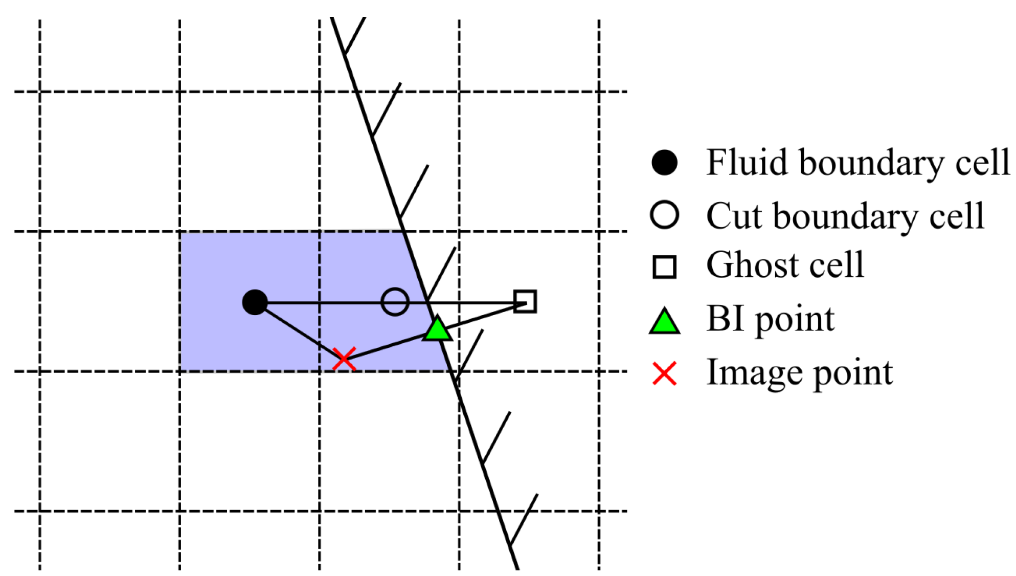
Once the cut boundary cells are determined, an outward surface norm is drawn from the IB face. The norm is drawn to pass through a cut boundary cell. The first fluid cell that the surface norm lands on is referred to as a fluid boundary cell. The fluid boundary cell must reside outside of the immersed boundary. A special type of cells called ghost cells (GC) is introduced to impose the boundary conditions. The ghost cells lie within the solid region of the immersed body [83]. The ghost cells are found by following similar steps but using the inward surface norm instead of the outward norm. One additional feature in the present method is lumping the pair of cut and fluid boundary cells together and treating them as one unit. Figure 2 illustrates the fluid boundary, cut boundary, and ghost cells, as well as the outward surface norm from an IB facet.
The image point (IP) of GC’s center, with respect to the IB facet, is used for imposing boundary conditions. Moreover, the point where the surface normal meets the IB facet is referred to as the body interceptor (BI) point. The steps of finding BI and IP are straightforward once GC is located.
In the present method, the free volume (volume outside of the solid) left after the IB faces cutting through the Cartesian mesh is absorbed by the adjacent fluid boundary cell. Furthermore, the solid cells and cut boundary cells are masked out from computations. The motion of the solid body causes the cut boundary cell’s free volume to change. A Lagrangian mesh handler tracks these volume changes, and the governing equations are updated accordingly.
Because the IP usually does not coincide with a fluid cell center, its flow properties need to be interpolated from the surrounding cells. This is carried out by using a trilinear interpolation on the stencil consisting of eight neighboring points. When identifying the interpolation stencil for each image point, BI points are first marked for each IB facet. Since ghost cells do not contain flow data, they are not used in the data interpolation stencil. Instead, they are replaced with the corresponding BI points. The polygon (3D or 2D) formed by connecting fluid boundary cells and BI points encompasses the image point and forms the given IP’s interpolation stencil.

4.3. Modification to Governing Equations

Since the fluid boundary cells residing near the IB’s vicinity have absorbed the free volume from the adjacent cut boundary cells, the governing equations on these cells need some modifications. These modifications are straightforward and simple to implement. In the source code, an “if” statement is used to activate the modifications only when IBs are present.
Before solving the volume fraction equation, an effective ψ value is calculated for each fluid boundary cell. The effective volume fraction takes into account the volume fraction of the fluid boundary cell and the volume fraction contribution from the cut boundary cells. The numerical integration of the convection-diffusion equation over moving grids introduced by Wu [84], Kundu et al. [85] and Marsooli and Wu [86] is adopted here to handle the aforementioned adjustment of cut boundary cells. In this method, the mass flux across cell faces in the convection terms of Equation (4) need to be recalculated, and the temporal derivative term of Equation (4) is discretized as
C V ψ t d V = ψ P n + 1 V P n + 1 ψ P n V P n Δ t
where V P = summation of fluid boundary cell volume and cut boundary cell’s free volume.
Similarly, if a cell is adjusted, the mass flux in the momentum Equation (9) is recalculated and the temporal derivative of momentum is modified as
C V t ( ρ m u ) d V = ρ m n + 1 u n + 1 P V P n + 1 ρ m n u n P V P n Δ t
In addition, the shear force on the lumped cell face is calculated with
S F = μ u I P n + 1 u I B n + 1 Δ S Δ l
where u I B = velocity of IB facet, which is added to the RHS source term; u I P = velocity at image point, which is interpolated from the surrounding cells and treated implicitly; and Δ l = distance between IP and IB points. Balaras [87] suggested interpolation of viscosity from the surrounding cells similar to velocity interpolation. However, the current implementation keeps the workflow simple by copying the viscosity directly from the fluid boundary cell.
The pressure Poisson Equation (15) is modified as follows to include the volume change on a combined fluid boundary cell during the time step:
a P p P + P N a N p N = f H ( u N ) A P f Δ S f + V P n + 1 V P n Δ t

5. Validations of the 3D Flow Model

The structure motion model was well tested by Forouzan et al. [88] in a study of hybrid simulation of fluid and structure interactions. The developed 3D flow model is validated herein with three recent experiments, by comparing the measured and calculated hydrodynamic forces or pressures on blocks generated by the impact of dam-break flows. The shear force on the structure is neglected, so the hydrodynamic force is calculated by integrating pressure over the boundary faces of the structure:
F = p f Δ S f

5.1. Impact Pressure on a Block Due to Dam-Break Flow

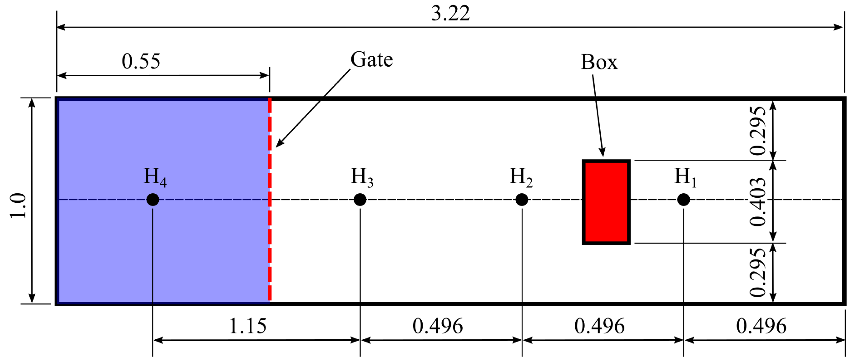
The first test case is the experiment carried by Kleefsman et al. [15] in a closed wave tank with 3.22 m in length, 1 m in width and 1 m in depth (Figure 3). A vertical gate was set up at 0.55 m from the upstream end to mimic a dam. A block was located 1.248 m downstream of the gate. The block was 0.161, 0.403, and 0.161 m in the longitudinal, lateral, and vertical directions, respectively. The block was fitted with pressure sensors along the centerline on the front and top faces. The initial bed downstream of the gate was dry. A dam-break flow was generated when the 0.55 m deep impound water was released by almost instantaneously lifting the gate. The water flowed over and around the block, and then back and forth inside the tank.
The numerical model uses a mesh consisting of nonuniform brick cells. The cell size around the block is about 5, 8, and 6 mm in the longitudinal, lateral, and vertical directions, respectively, and gradually increases upstream and downstream from the block and with the height above the bed. The bed friction coefficient C b f is calibrated as 0.005. Figure 4 depicts the variations of water levels at wave gauges H2 and H4. The water level at H4 in the reservoir zone dropped first as the dam-break wave went downstream, and then rose when the reflected wave propagated back. Opposite variations occurred for the water level at H2 in the downstream zone. The numerical results agree well with the experimental data. The root-mean-square errors are 0.025 and 0.020 m at H2 and H4, respectively, and 4.6% and 3.7% of the initial reservoir water height.
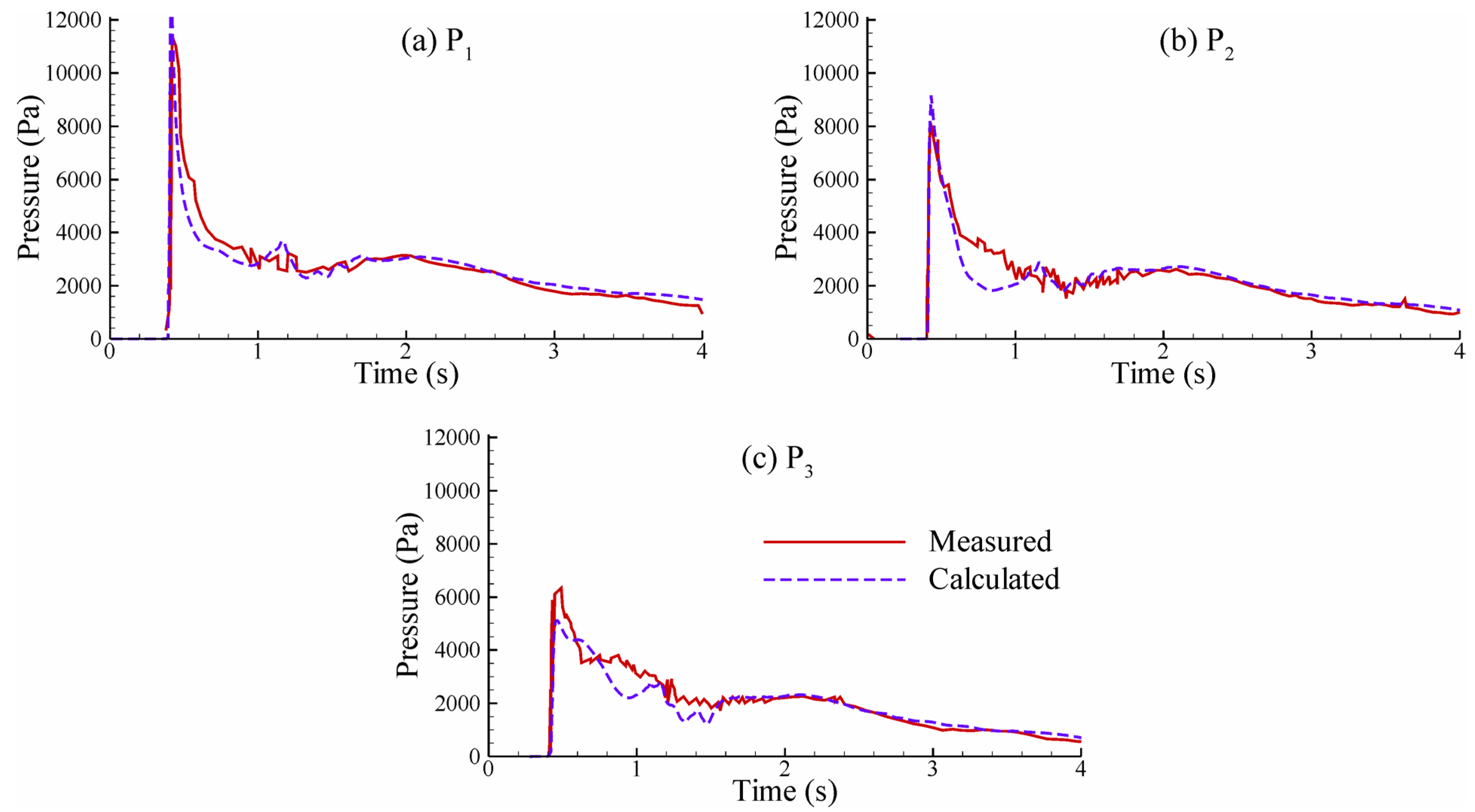
Figure 5 shows that the flow model is capable of capturing the pressure variations generated by the impact of dam-break flow recorded by sensors P1, P2, and P3, which are installed 0.021, 0.061, and 0.101 m, respectively, above the bed in the center-vertical line on the front face of the block. The model correctly captures the initial wave arrival time. The pressures increased rapidly to the peak values and decreased to about the hydrostatic pressures. Larger peak pressures occurred at lower heights above the bed. The root-mean-square errors are 6.0%, 6.1%,and 6.8% of the measured maximum pressures at P1, P2, and P3, respectively.

5.2. Impact Force on a Block Due to Dam-Break Flow

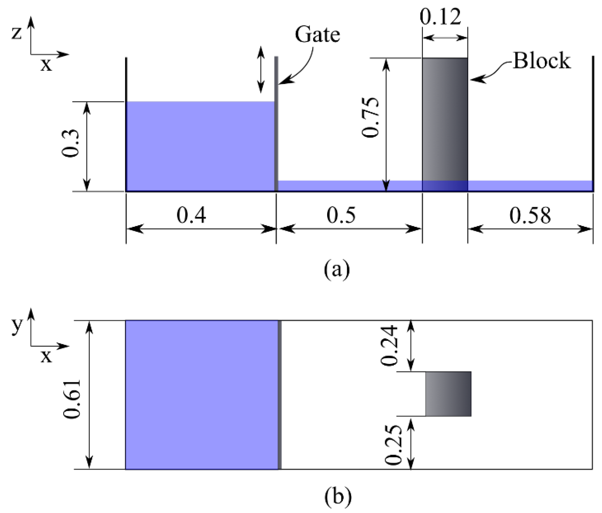
The 3D flow model is further tested by using the measured forces on blocks due to dam-break flows in two experimental cases. One case is the experiment carried out by Profs. Catherine Petroff and Harry Yeh at the University of Washington, Seattle, USA [14]. The experiment used a closed wave tank 0.61 m in width and 1.58 m in length (Figure 6). A tall block with a square base (0.12 m by 0.12 m) was located 0.5 m downstream of the gate. The upstream impound water depth was 0.3 m, and the downstream initial water depth was 0.01 m. Once the gate was opened, the water flow hit the block and then was deflected around the block and reflected from the downstream wall.
In the numerical simulation, the bed friction coefficient C b f = 0.005 as calibrated. The mesh is similar to that in the previous case. The cell size around the block is 4 mm long and 5 mm wide in the horizontal (x and y) directions, and gradually increases upstream and downstream from the block. The vertical grid size starts at 2.5 mm near the bed and gradually increases with the height above the flume bed.
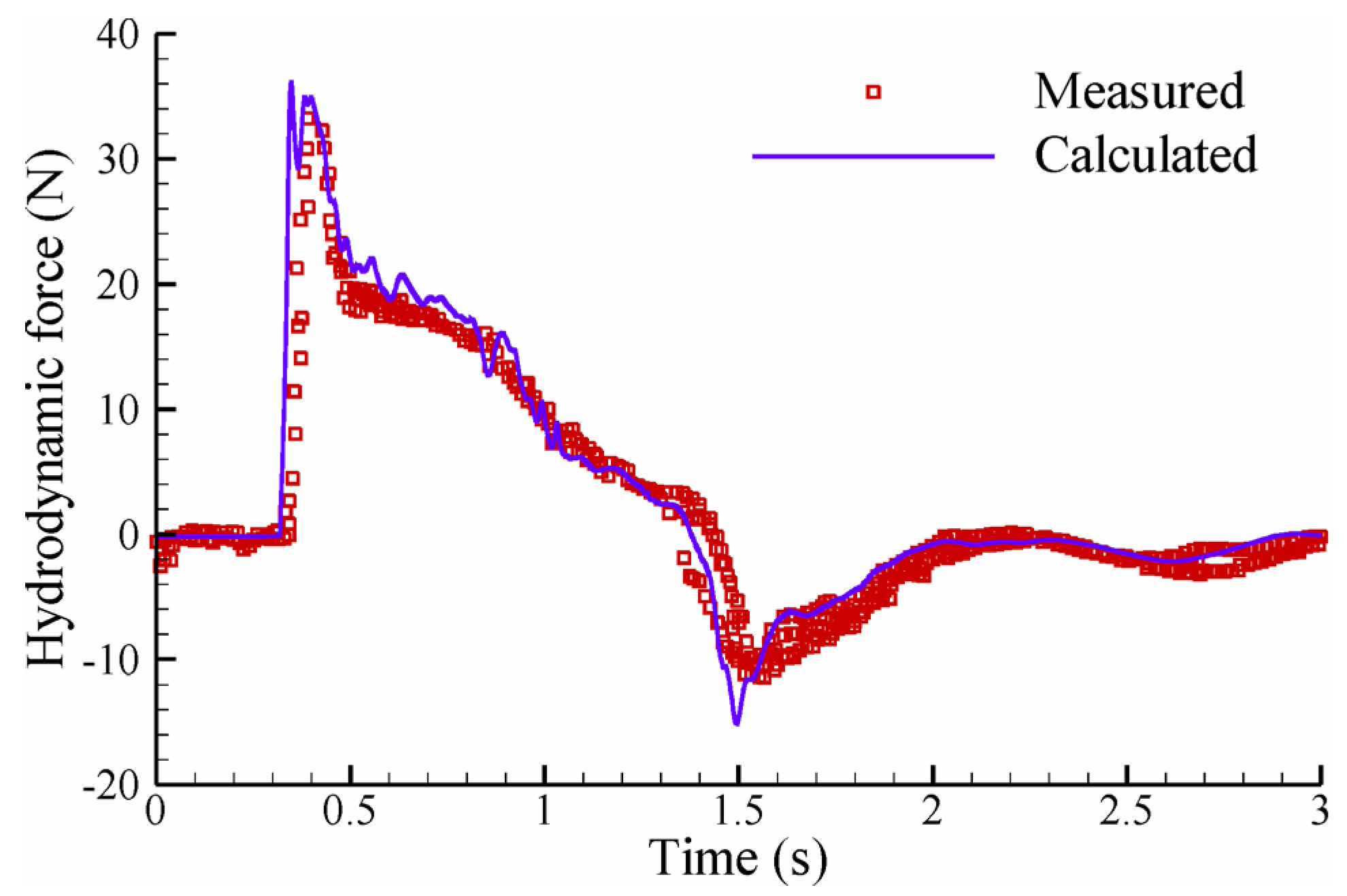
Figure 7 compares the calculated and measured hydrodynamic forces on the block. The experimental data are digitized from a plot of Gómez-Gesteira and Dalrymple [14]. The temporal evolution of the hydrodynamic force is well predicted by the numerical model. The simulation results shown in Figure 7 are obtained by assuming instant gate opening, which causes the initial dam-break wave to arrive about 0.1 s earlier than the experimental data. The force becomes negative when the wave reflected from the downstream wall hits the downstream side of the block. The numerical model slightly overpredicts the peak impact forces of the dam-break wave and the reflected wave. The root-mean-square error is 10.3% of the measured maximum hydrodynamic force. The relative error is smaller if the early arrival of the calculated dam-break wave is excluded.
The other case is chosen from the experiments of Arnason [11]. The experimental setup is similar to Figure 6, with large dimensions. The flume was 16.62 m long, 0.61 m wide, and 0.45 m deep. The gate was installed at 5.9 m from the upstream end. The initial water level was 0.25 m in the reservoir and 0.02 m downstream of the gate in the chosen test case. A 0.12 m long square block was rigidly mounted. The front face of the block was placed 5.2 m away from the gate. This distance is assumed to be sufficient to develop a turbulent bore front.
Three different meshes (M1 to M3) with varying grid resolutions are used to analyze the effect of cell size. Mesh M1 has the least number of cells, slightly more than 0.9 million cells. The mesh is nonuniform, and the cells near the structure are 80, 80, and 50 mm in the longitudinal, lateral and vertical directions, respectively. In mesh M2, the cell size close to the structure remains unaltered, but the mesh is refined in other sections of the domain, especially between gate and structure. The mesh M2 consists of more than 1.1 million cells. In mesh M3, cells are refined further throughout the entire flow domain; the cells near the structure are 70, 60, and 30 mm long in the three directions, and the total number of cells is close to 2 million. The bed friction coefficient C b f = 0.005 for the three meshes.
Figure 8 shows the time history of the hydrodynamic forces calculated using the three meshes. The model gives an earlier arrival time of the hydraulic bore. A non-physical force appears around 3 s for coarse meshes M1 and M2 but not for the fine mesh M3. This force is caused by adverse numerical diffusion in the volume fraction field. Furthermore, the peak impact force is delayed when the mesh is refined. The root-mean-square errors are 15.7%, 15.9%, and 13.8% of the measured maximum hydrodynamic force for meshes M1, M2 and M3, respectively. Like the previous case, the large relative errors are partly due to the early arrival of the calculated dam-break waves. Overall, the finest mesh gives the most accurate results. In addition, the numerical results exhibit some high-frequency waves, which were not recorded in the experiments. This may be related to numerical schemes and needs to be investigated further.

6. Validations of the Coupled Fluid-Structure Model

The large-scale experiments of tsunami impact on bridges conducted by Istrati [9] are one of the few recent experiments considering dynamic fluid-structure interactions. These experiments used different wave input conditions and bridge configurations, with a 1:5 scaled bridge model to minimize the scaling effects. Thus, these experiments are used to validate the present fluid-structure interaction model.

6.1. Experiment Setup

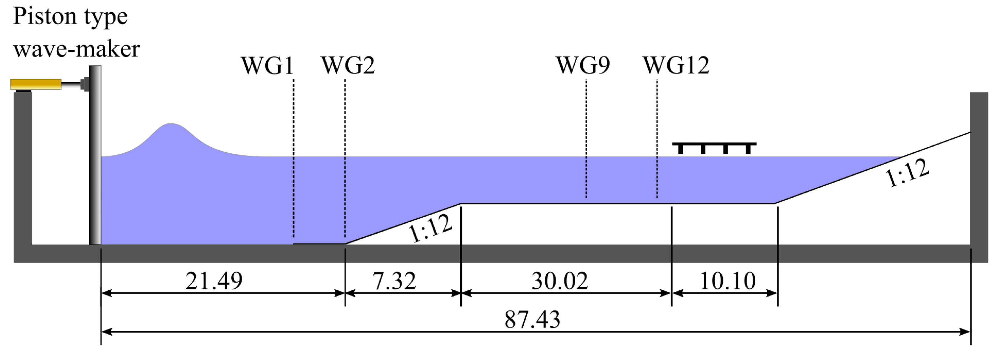
The flume was 104.24 m long, 3.66 m wide, and 4.57 m deep. There was a 21.49 m long flatbed region next to the wave generator. The flume bed was raised to form a false bed through a 7.32 m long ramp with a 1:12 slope, and another ramp with a 1:12 slope was installed at the flume end to dissipate the wave energy and thereby minimize the reflection (Figure 9). The still water depth near the wave generator was 2.0 m. Solitary waves with different heights were generated, which exhibited nonbreaking and breaking features in front of the bridge model.
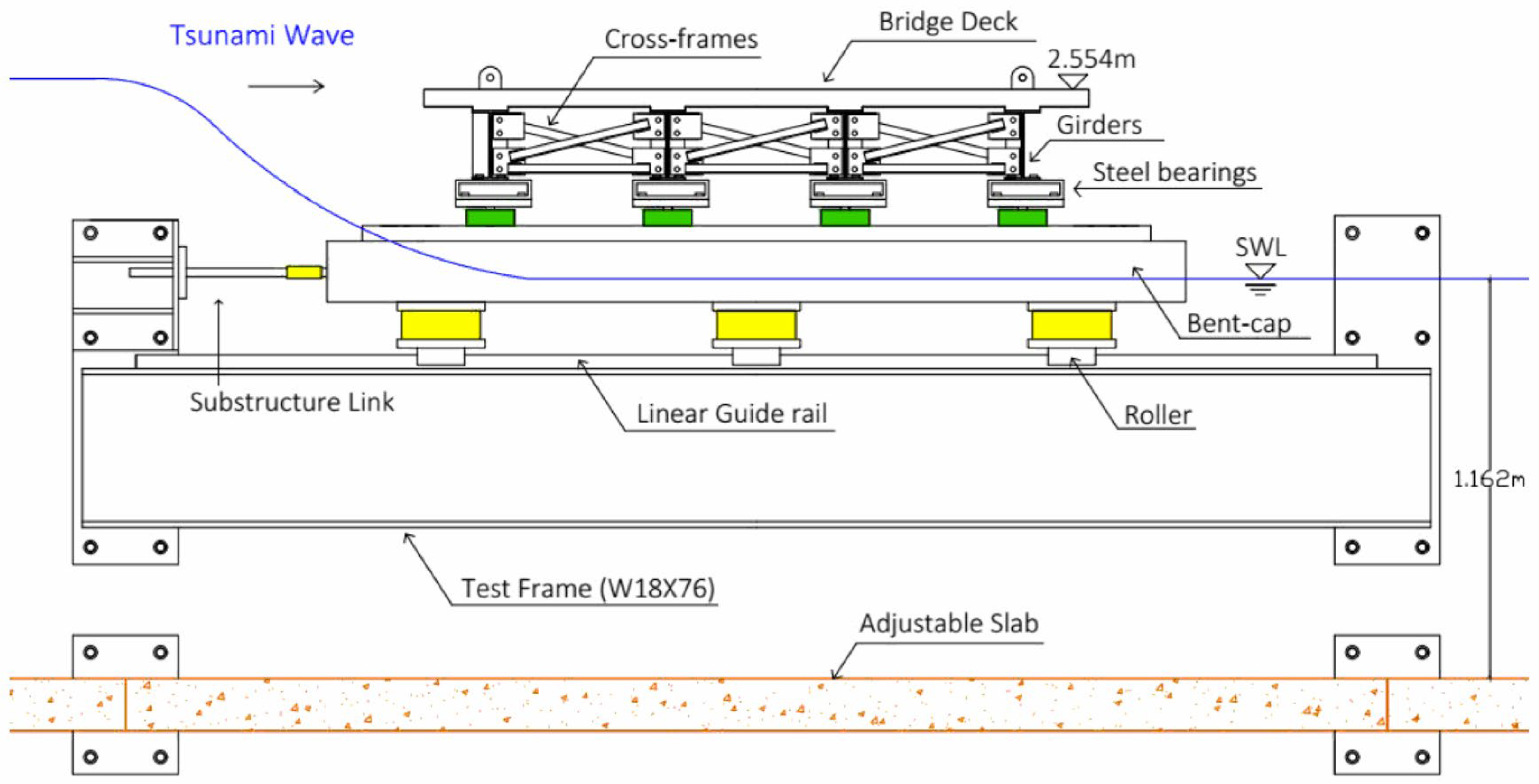
The 1:5 scale bridge model was 1.938 m wide and 3.456 m long, and the total bridge height was 0.264 m. The width and length were measured along and normal to the wave propagation direction, respectively. The bridge had a reinforced concrete deck and W8x13 steel I-beams for its four girders. The bridge was mounted on a substructure assembly, which consisted of two HSS7x5 bent caps. The substructure was mounted on linear guide rails and rollers and placed onto test frames (W18x76 beam) that were rigidly bolted to the flume walls. The connections between the bridge superstructure and substructure could be changed to achieve different bridge dynamic characteristics. Figure 10 depicts a side view of the bridge, substructure, and test frame. Further details of the bridge model can be found in Istrati [9].
The connection types used in the tests were steel bearing, elastomeric bearing, shear keys, and springs between the substructure and the test frame. A total of ten configurations of bridge structure were used in the experiments. The most rigid case (ST1) consisted of steel bearings, shear keys, and rigid links at the substructure. The second configuration (ST2) was similar to ST1, but steel bearings were replaced with elastomeric ones. ST5 had connections similar to ST2, but plywood sections perpendicular to the girders were used to capture air. Configurations ST2 and ST5 are considered in the present numerical study.

6.2. Numerical Flow Domain and Structure Model Setup

Due to computational time and resource constraints, the flow is assumed to be two-dimensional as the bridge span completely occupies the wave flume’s width, and a part of the flatbed zone next to the wave maker is not included in the computational domain. Preliminary simulations are conducted to identify the regions where water may reach vertically. The final flow solution domain is outlined in Figure 11.
In the computational mesh, the cell size along the x-direction is 4 cm near the wave generation boundary (left side of Figure 11) and 2 cm near the bridge. For bore or breaking wave conditions, the x-direction cell size gradually shrinks to 2 cm near the region where the wave breaking occurs. However, for nonbreaking wave conditions, the cell size can be 4 cm for most of the distance between the left boundary and the bridge. The z-direction cell size starts at about 5 cm at the flume bed, gradually decreases to 2 cm at the SWL, and is kept at 2 cm in the region above the SWL.
The bridge has complex geometric features that are challenging to model. Therefore, it is significantly simplified in the numerical simulation, as shown in Figure 12. Most of the simplifications align with the geometric model of Xiang et al. [90]. Additionally, the substructure is not included in the simulations.
In the fully coupled fluid-structure simulations, due to the 2D flow assumption, the structure’s motion had to be constrained to two dimensions. Additionally, the analyzed bridge configurations have shear keys to stop rotational motion, so the bridge is modeled as a single degree-of-freedom damped vibration system. The connection’s stiffness is back-calculated using the mass and dominant natural frequency for the selected data series. The elastomeric bearings are assumed to have constant stiffness.
The bridge’s dry mass without any instrumentation is used in the simulations, which is roughly 1287.3 kg. During the experiments, the bridge might undergo an effective mass increase due to water accumulation as the water flooded the structure, as well as due to the added or virtual mass effect as surrounding water accelerates with the submerged bridge. For the current bridge geometry, water accumulation is less likely and thus is neglected. The virtual mass is not considered additionally since the current simulations consider the interactions between fluid and structure inherently.
The experimental setup did not contain any dedicated damping devices, but force measurements showed that the system experienced damping. Numerical simulations with no damping show large oscillations in the restoring force throughout the simulation time, which do not match the experimental observations. Thus, damping is explicitly introduced in the generalized alpha method through the damping matrix [C]. A constant 5% damping ratio is used in the simulations.

6.3. Comparison of Numerical Results and Experimental Data

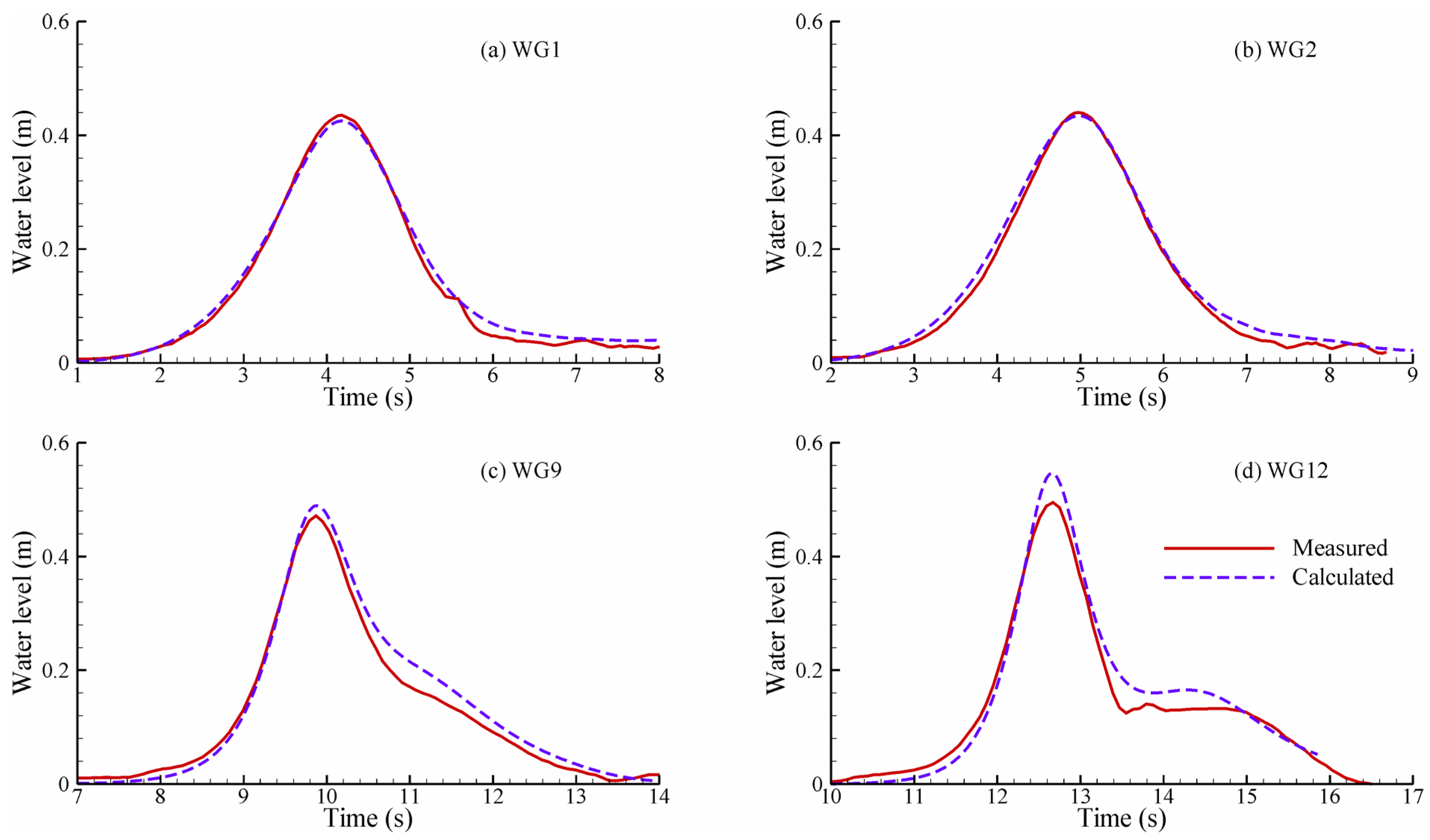
Figure 13 compares the water surface variations for the solitary wave of height H = 0.42 m at different wave gauges along the flume. The input waves generated in the numerical model agree well with the experimental input waves, except at the tailing part where the experimental waves deviate from solitary waves. Figure 13c,d show that the numerical wave is higher than the experimental one at WG9 and WG12. This may be caused by the assumption of a two-dimensional flow and the reduction in the flow domain length near the wave maker. The root-mean-square errors of the calculated water levels are 0.011, 0.012, 0.021 and 0.025 m at WG1, WG2, WG9 and WG12, respectively.
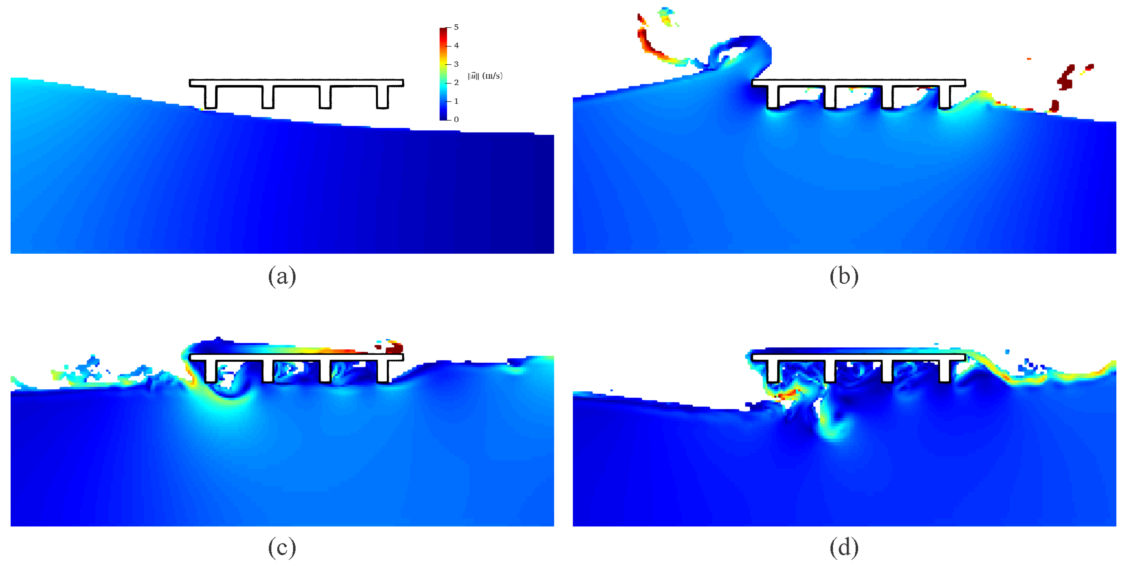
Figure 14 shows several snapshots of the simulated resultant flow velocity contour map when the solitary wave of H = 0.42 m hits the bridge model. The wave crest is deflected upward by the bridge model, while water underneath the deck flows around the lower tips of the girders and splashes downstream of the bridge. A part of the deflected wave is reflected and another part overtops the bridge deck. As the water level recedes, the overtopping wave portion falls over the deck tail and complex flows appear around and between the girders. Some air is trapped between the girders.
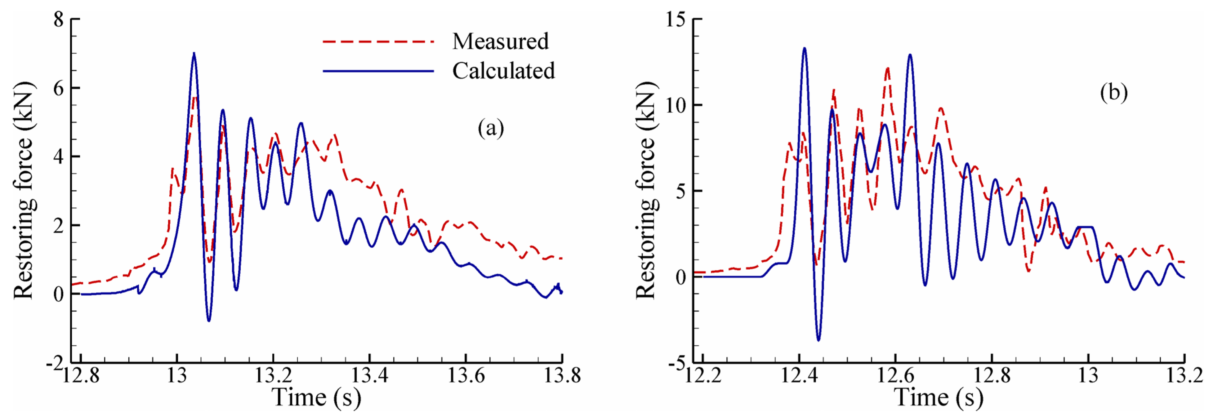
Figure 15 shows the time history of restoring forces ( [ K ] x ) for bridge configuration ST2 under nonbreaking solitary waves of 0.42 and 0.55 m in height. The natural frequency of the bridge is calibrated as 18.5 Hz based on the measured force variation under the solitary wave of H = 0.42 m, and applied to the case of H = 0.55 m. With this estimate, the model predicts well the initial variation pattern of restoring forces under both wave heights. The root-mean-square errors are 17.7% and 20.6% of the measured maximum restoring forces in the cases of H = 0.42 and 0.55 m, respectively.
Figure 16 shows the time history of restoring forces for bridge configuration ST5 under solitary waves of H = 0.7 and 0.9 m. These solitary waves are nearly breaking or broken before hitting the structure. The natural frequency of the bridge is calibrated as 13 and 11.5 Hz based on the measured restoring force variations under these two wave conditions. The model predicts well the initial variation pattern of restoring forces under both waves. In both Figure 15 and Figure 16, the variation frequencies of the calculated and measured forces exhibit larger deviations in the end period because the natural frequencies are calibrated in the initial period. The root-mean-square errors are 17.8% and 40.1% of the measured maximum restoring forces in the cases of H = 0.7 and 0.9 m, respectively.
From the above four cases, the model overpredicts the restoring forces in the initial impact period under low waves but underpredicts the force under high waves. First, this may be because more air entrained into water when the waves are broken or nearly breaking. The present model does not consider the effect of air entrainment. Second, the same 5% damping coefficient is used in all the cases. In fact, the damping efficiency can vary with wave heights that give different locations and distribution of the impact force on the structure, as well as with bridge configurations that have different damping mechanisms in the structure. It is not straightforward to identify a suitable damping coefficient that works well for all the flow cases and bridge configurations. Third, the shear force between the structure and the flow acts as another source of damping effect. This force is neglected in current simulations since it is much smaller than the pressure force. Moreover, the structure had shear keys, which could stop the rotation and large horizontal motion of the structure; however, this is not included in the structural model that uses a single degree-of-freedom system (SDOF). A multi-degree-of-freedom bridge model may improve the numerical results. In addition, the assumption of constant stiffness for elastomeric bearings can also be a source of errors, because the properties of elastomeric bearings depend on the level and rate of shear strain [9] and can affect the bridge dynamics (e.g., natural frequency).

7. Discussion

The coupled fluid-structure model validated in the previous section is applied to assess the effect of structure flexibility on the impact force and is compared with an uncoupled model, as described in the following text.

7.1. Comparison of Forces on Structures with Different Flexibilities

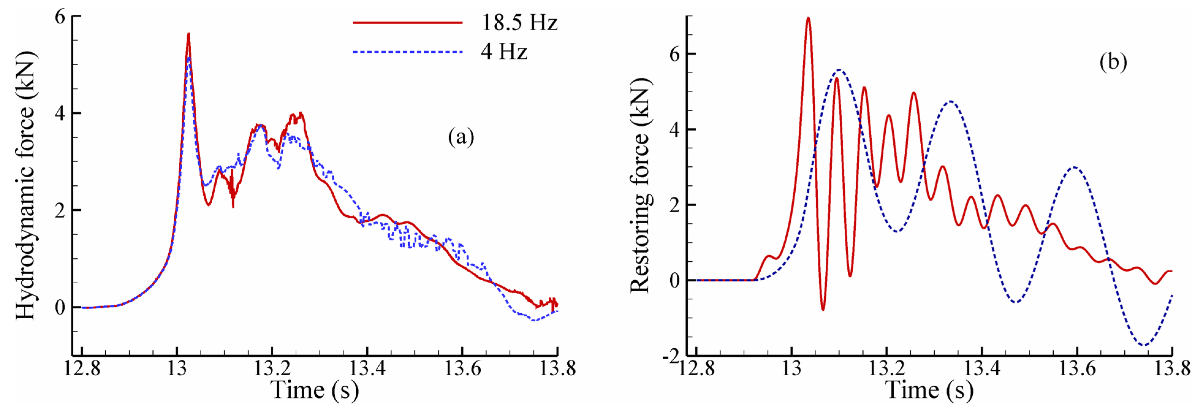
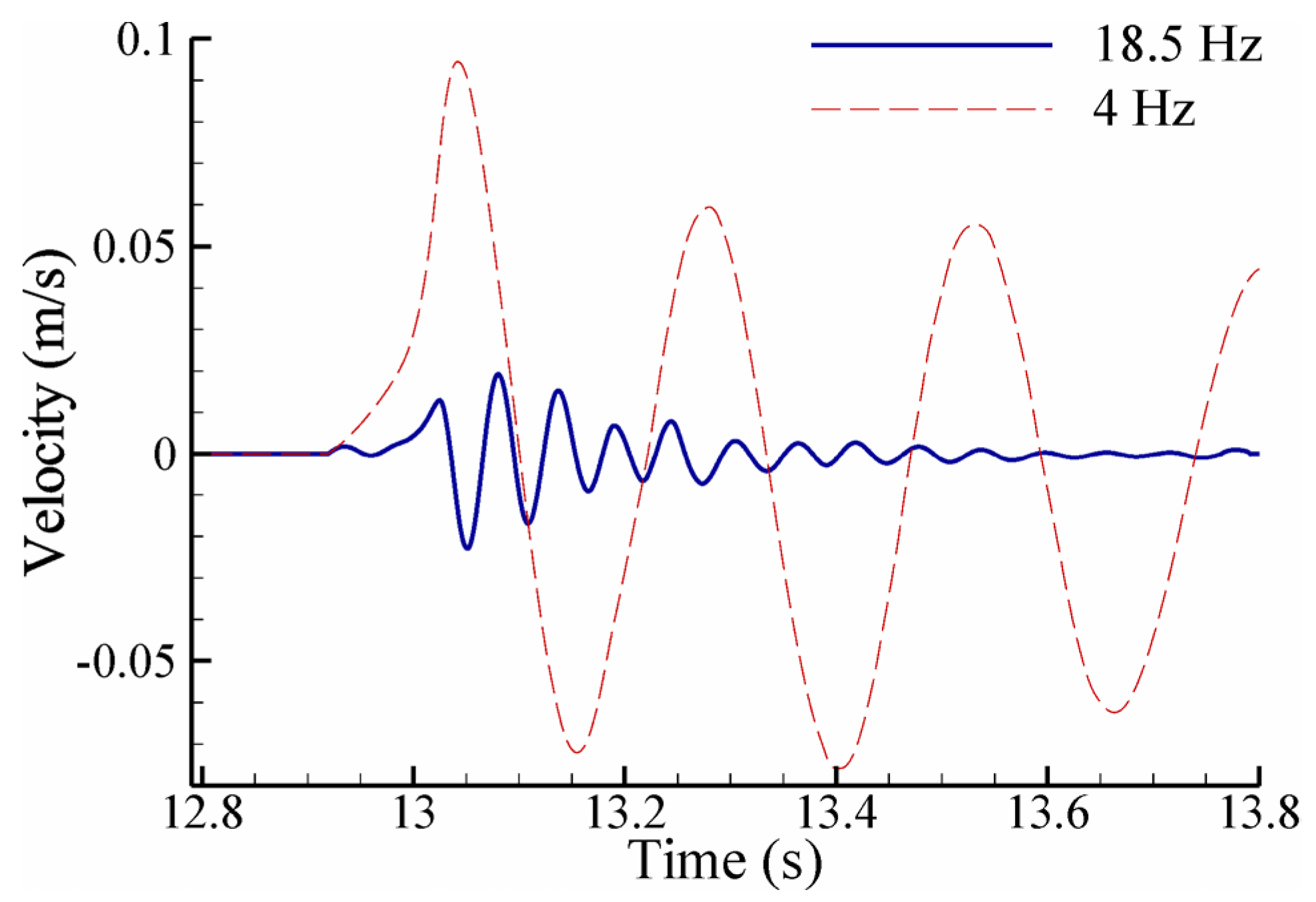
Figure 17a compares the calculated hydrodynamic forces on the bridge configuration ST2 with varying flexibility under a solitary wave of 0.42 m in height. Figure 17b compares the corresponding restoring forces. The hydrodynamic force is the resultant pressure force in the front of the structure. In addition to the calibrated natural frequency of 18.5 Hz, a hypothetical natural frequency of 4 Hz is used. Figure 18 shows the calculated structure velocities with these two natural frequencies.
Figure 17a shows that the hydrodynamic forces between the two flexible configurations exhibit small deviations at the initial impact. The deviations are slightly above 5%. It seems that the hydrodynamic force is not very sensitive to the natural frequency. This may be because the structure velocity is small, as shown in Figure 18. The structure velocity increases with decreasing natural frequency (increasing flexibility), but the magnitude of structure velocity is much smaller than that of flow velocity. However, the results in Figure 17b show that the restoring force of the structure significantly depends on the structure’s natural frequency. The maximum hydrodynamic and restoring forces increase with natural frequency or decrease with increasing flexibility of the structure.

7.2. Comparison of Forces Calculated by Fully Coupled and Uncoupled Simulations

Further investigation of the importance of fully coupled fluid-structure simulations is carried out by comparing the restoring forces calculated by fully coupled and uncoupled models. The uncoupled model uses an external structural solver that is implemented in a simple Matab® script. First, the fluid simulation is run assuming that the structure is rigid. The calculated hydrodynamic force is then passed to the external structural solver. In the uncoupled simulation, the restoring force of the structure is calculated, but the structure motion is not fed back to the flow model.
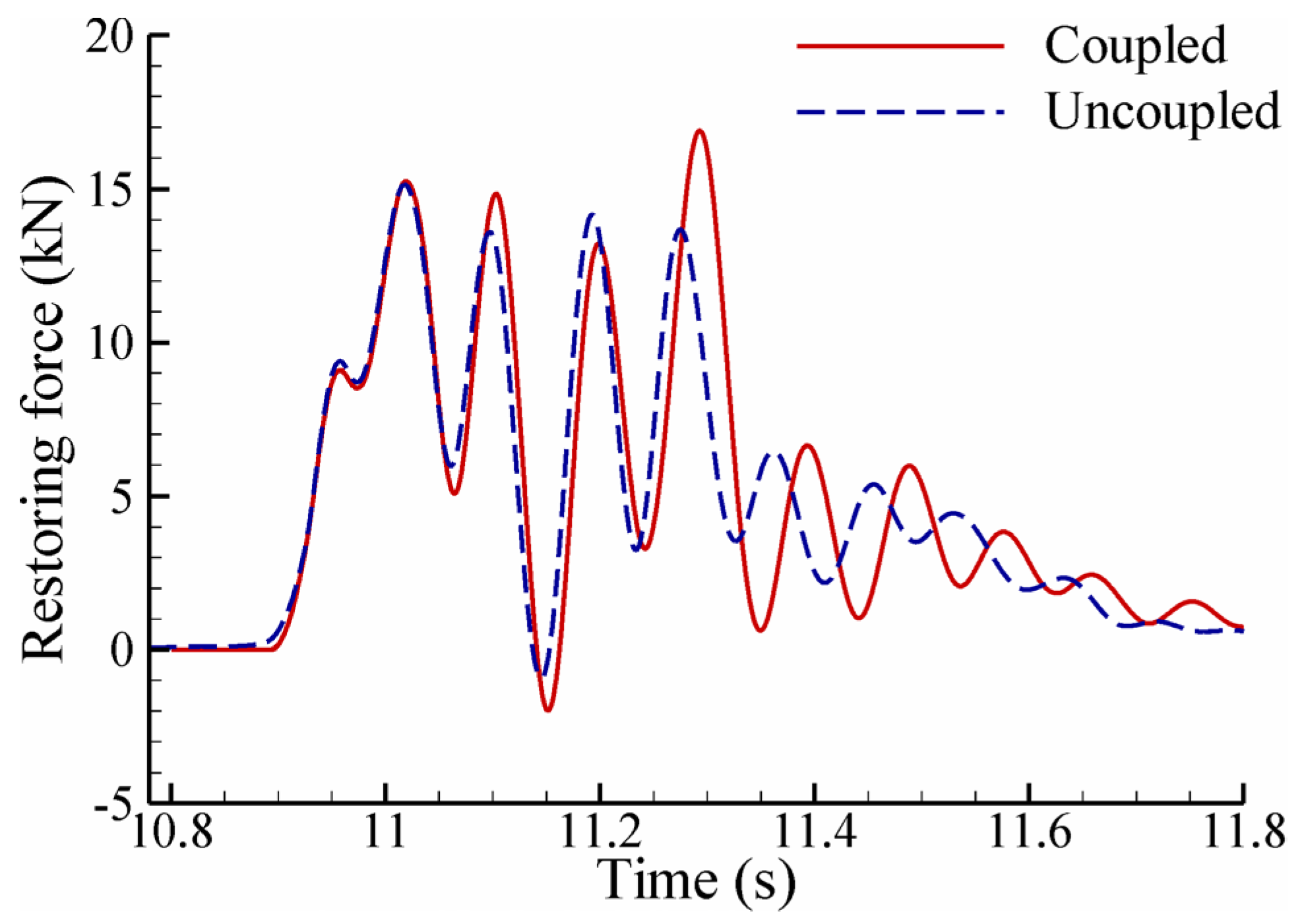
Figure 19 compares the restoring forces calculated by the fully coupled and uncoupled models on bridge configuration ST2 under the solitary wave of H = 0.42 m. The calibrated natural frequency of 18.5 Hz is used for the results in Figure 19a, and the hypothetical natural frequency of 4 Hz is used for the results in Figure 19b. For the stiffer structure (high natural frequency), the uncoupled simulation gives a slightly lower restoring force at the initial impact and a higher one in the following periods than the coupled simulation. For the more flexible structure (low natural frequency), almost the same restoring force at initial impact is obtained by the fully coupled and uncoupled simulations, whereas after the initial impact, the uncoupled simulation gives a higher restoring force than the fully coupled simulation.
Figure 20 shows the restoring forces calculated by the fully coupled and uncoupled models on bridge configuration ST5 under the bore (breaking solitary wave) of H = 0.9 m. Unlike the case of the nonbreaking solitary wave shown in Figure 19, the restoring force calculated by the uncoupled simulation in the bore case is smaller than that calculated by the coupled simulation shown in Figure 20. Both Figure 19 and Figure 20 show that the deviations between the coupled and uncoupled simulations increase with time and the uncoupled simulation gives shorter periods for restoring force variations than the fully coupled simulation.
The aforementioned analyses demonstrate that the restoring force depends on the structural dynamics and the feedback coupling between fluid and structure. Whenever available, it is advisable to consider the fully coupled simulations when analyzing structures subjected to tsunami-like loading. The immersed boundary approach used by the present study has a minimal overhead on the overall simulation. Certainly, the computational loading of the structural analysis will increase as the complexity of the structure increases.

8. Conclusions

A 3D fully-coupled fluid-structure model has been developed in this study to understand the importance of dynamic characteristics of structures and the necessity of fully coupled fluid-structure models when subjected to tsunami-like loading. To simulate the propagation of tsunamis, the volume fraction transport equation is solved along with the 3D Navier–Stokes equations by employing the finite volume method. The model predicts the forces induced by hydraulic bores very closely to experimental measurements. The structure motion equation is solved using the generalized alpha method. The structure motion is fed back into the fluid solver via a technique that combines a sharp-interface immersed boundary method with the cut-cell method.
The fully coupled 3D flow-structure model has been tested with existing experimental data for a 1:5 scale bridge model under nonbreaking and breaking solitary waves. The simulated wave propagation and structure restoring forces agree generally well with the measured data. Then, the fully coupled fluid-structure model is applied to assess the effect of structure flexibility on responses to tsunami-like loading. The simulations show that the restoring forces depend highly on the dynamic characteristics of structures, whereas the hydrodynamic forces on flexible structures deviate little if the structure velocity is much smaller than the flow velocity. The maximum hydrodynamic and restoring forces decrease with increasing structure flexibility,
Moreover, the present fully coupled model has been compared with an uncoupled model. The restoring forces calculated by the uncoupled simulations in the nonbreaking and breaking solitary wave cases can be larger or smaller than those calculated by the coupled simulations, whereas the uncoupled simulations give shorter periods for the restoring force variations than the fully coupled simulations in both wave cases. It is demonstrated that the restoring force depends on the structural dynamics and the feedback coupling between fluid and structure. Whenever feasible, it is preferable to consider the fully coupled simulations when analyzing structures subjected to tsunami-like loading.
However, the developed flow-structure model has the following limitations. First, the developed flow model solves incompressible Navier–Stokes equations, the compressibility effect of trapped air between the girders cannot be captured correctly. A compressible flow solver for the air phase needs to be used if such effects are to be considered. Second, the developed flow model requires a considerable amount of computation time, so computer resources and the computation efficiency are still the main concerns when the model is applied to transient flows in large domains. Third, the flow model uses the simple sub-grid turbulence model, so advanced, higher-order turbulence models and large eddy simulations need to be explored in the future. Fourth, the structural model assumes a constant structure mass and damping. However, an actual structure may undergo mass changes due to water accumulation, absorption, debris accumulation, etc., and the damping factor may vary as the structure is submerged. Fifth, the developed model has been tested only for small displacements and it does not consider structure deformations, for which a 3D finite-element structure model is needed. Finally, data scarcity is a major obstacle faced in model validations. Additional reliable experimental data would help to refine the numerical model further.

Author Contributions

Conceptualization, D.S.P.A.B. and W.W.; methodology, D.S.P.A.B. and W.W.; software, D.S.P.A.B.; validation, D.S.P.A.B. and W.W.; formal analysis, D.S.P.A.B.; investigation, D.S.P.A.B. and W.W.; resources, W.W.; data curation, D.S.P.A.B.; writing—original draft preparation, D.S.P.A.B. and W.W.; writing—review and editing, W.W.; visualization, D.S.P.A.B.; supervision, W.W.; project administration, W.W.; funding acquisition, W.W. All authors have read and agreed to the published version of the manuscript.

Funding

This research received no external funding.

Data Availability Statement

Data are available from the authors by request.

Conflicts of Interest

The authors declare no conflict of interest.

References

  1. Abraham, A.O. Extreme Wave Impact on a Flexible Plate. Master’s Thesis, Massachusetts Institute of Technology, Cambridge, MA, USA, 2016. [Google Scholar]
  2. Al-Faesly, T.; Palermo, D.; Nistor, I.; Cornett, A. Experimental modeling of extreme hydrodynamic forces on structural models. Int. J. Prot. Struct. 2012, 3, 477–505. [Google Scholar] [CrossRef]
  3. Al-Faesly, T.Q. Extreme Hydrodynamic Loading on Near-Shore Structures. Ph.D. Thesis, University of Ottawa, ON, Canada, 2016. [Google Scholar]
  4. Arikawa, T. Structural behavior under impulsive tsunami loading. J. Disaster Res. 2009, 4, 377–381. [Google Scholar] [CrossRef]
  5. Arnason, H. Interactions between an Incident Bore and a Free-Standing Coastal Structure. Ph.D. Thesis, University of Washington, Seattle, WA, USA, 2005. [Google Scholar]
  6. Asadollahi, N.; Nistor, I.; Mohammadian, A. Numerical investigation of tsunami bore effects on structures, part I: Drag coefficients. Nat. Hazards 2019, 96, 285–309. [Google Scholar] [CrossRef]
  7. Asakura, R.; Iwase, K.; Ikeya, T.; Takao, M.; Kaneto, T.; Fujii, N.; Ohmori, M. The tsunami wave force acting on land structures. Coast. Eng. 2003, 2002, 1191–1202. [Google Scholar]
  8. Aureli, F.; Dazzi, S.; Maranzoni, A.; Mignosa, P.; Vacondio, R. Experimental and numerical evaluation of the force due to the impact of a dam-break wave on a structure. Adv. Water Resour. 2015, 76, 29–42. [Google Scholar] [CrossRef]
  9. Balaras, E. Modeling complex boundaries using an external force field on fixed Cartesian grids in large-eddy simulations. Comput. Fluids 2004, 33, 375–404. [Google Scholar] [CrossRef]
  10. Bao, Y.; Donev, A.; Griffith, B.E.; McQueen, D.M.; Peskin, C.S. An immersed boundary method with divergence-free velocity interpolation and force spreading. J. Computat. Phys. 2017, 347, 183–206. [Google Scholar] [CrossRef]
  11. Bathe, K.-J. Conserving energy and momentum in nonlinear dynamics: A simple implicit time integration scheme. Comput. Struct. 2007, 85, 437–445. [Google Scholar] [CrossRef]
  12. Berberović, E.; van Hinsberg, N.P.; Jakirlić, S.; Roisman, I.V.; Tropea, C. Drop impact onto a liquid layer of finite thickness: Dynamics of the cavity evolution. Phys. Rev. E 2009, 79, 036306. [Google Scholar] [CrossRef]
  13. Bernardini, M.; Modesti, D.; Pirozzoli, S. On the suitability of the immersed boundary method for the simulation of high-Reynolds-number separated turbulent flows. Comput. Fluids 2016, 130, 84–93. [Google Scholar] [CrossRef]
  14. Boris, J.P.; Book, D.L. Flux-corrected transport. I. SHASTA, a fluid transport algorithm that works. J. Computat. Phys. 1973, 11, 38–69. [Google Scholar] [CrossRef]
  15. Brackbill, J.U.; Kothe, D.B.; Zemach, C. A continuum method for modeling surface tension. J. Computat. Phys. 1992, 100, 335–354. [Google Scholar] [CrossRef]
  16. Bricker, J.D.; Nakayama, A. Contribution of Trapped air, deck superelevation, and nearby structures to bridge deck failure during a tsunami. J. Hydraul. Eng. 2014, 140, 05014002. [Google Scholar] [CrossRef]
  17. Cacace, S.; Cristiani, E.; Ferretti, R. Blended numerical schemes for the advection equation and conservation laws. ESAIM Math. Model. Numer. Anal. 2017, 51, 997–1019. [Google Scholar] [CrossRef]
  18. Cardiff, P.; Karač, A.; De Jaeger, P.; Jasak, H.; Nagy, J.; Ivanković, A.; Tuković, Ž. An open-source finite volume toolbox for solid mechanics and fluid-solid interaction simulations. arXiv 2018, arXiv:1808.10736. [Google Scholar]
  19. Chan, I.-C.; Liu, P.L.-F. On the runup of long waves on a plane beach. J. Geophys. Res. Ocean. 2012, 117, C08006. [Google Scholar] [CrossRef]
  20. Chanson, H. Tsunami surges on dry coastal plains: Application of dam break wave equations. Coast. Eng. J. 2006, 48, 355–370. [Google Scholar] [CrossRef]
  21. Chen, L.F.; Zang, J.; Hillis, A.J.; Morgan, G.C.J.; Plummer, A.R. Numerical investigation of wave–structure interaction using OpenFOAM. Ocean Eng. 2014, 88, 91–109. [Google Scholar] [CrossRef]
  22. Chung, J.; Hulbert, G.M. A time integration algorithm for structural dynamics with improved numerical dissipation: The generalized-α method. J. Appl. Mech. 1993, 60, 371–375. [Google Scholar] [CrossRef]
  23. Clarke, D.K.; Salas, M.D.; Hassan, H.A. Euler calculations for multielement airfoils using Cartesian grids. AIAA J. 1986, 24, 353–358. [Google Scholar] [CrossRef]
  24. Conde, J.M.P. Comparison of different methods for generation and absorption of water waves. Rev. Eng. Térmica 2019, 18, 71–77. [Google Scholar] [CrossRef]
  25. Damián, S.M. An Extended Mixture Model for the Simultaneous Treatment of Short and Long Scale Interfaces. Ph.D. Thesis, Universidad Nacional del Litoral, Santa Fe, Argentina, 2013. [Google Scholar]
  26. Deshpande, S.S.; Anumolu, L.; Trujillo, M.F. Evaluating the performance of the two-phase flow solver interFoam. Computat. Sci. Discov. 2012, 5, 014016. [Google Scholar] [CrossRef]
  27. Earthquake Engineering Research Institute. The Japan Tohoku Tsunami of March 11, 2011; EERI Special Earthquake Report; EERI: Oakland, CA, USA, 2011. [Google Scholar]
  28. Fritz, H.M.; Petroff, C.M.; Catalán, P.A.; Cienfuegos, R.; Winckler, P.; Kalligeris, N.; Weiss, R.; Barrientos, S.E.; Meneses, G.; Valderas-Bermejo, C.; et al. Field survey of the 27 February 2010 Chile tsunami. Pure Appl. Geophys. 2011, 168, 1989–2010. [Google Scholar] [CrossRef]
  29. Forouzan, B.; Baragamage, D.S.A.; Shaloudegi, K.; Nakata, N.; Wu, W. Hybrid simulation of a structure to tsunami loading. Adv. Struct. Eng. 2019, 23, 136943321985784. [Google Scholar] [CrossRef]
  30. Gingold, R.A.; Monaghan, J.J. Smoothed particle hydrodynamics: Theory and application to non-spherical stars. Mon. Not. R. Astron. Soc. 1977, 181, 375–389. [Google Scholar] [CrossRef]
  31. Gopala, V.R.; van Wachem, B.G.M. Volume of fluid methods for immiscible-fluid and free-surface flows. Chem. Eng. J. 2008, 141, 204–221. [Google Scholar] [CrossRef]
  32. Gómez-Gesteira, M.; Dalrymple, R.A. Using a three-dimensional smoothed particle hydrodynamics method for wave impact on a tall structure. J. Waterw. Port Coast. Ocean Eng. 2004, 130, 63–69. [Google Scholar] [CrossRef]
  33. Hayatdavoodi, M.; Seiffert, B.; Ertekin, R.C. Experiments and computations of solitary-wave forces on a coastal-bridge deck. Part II: Deck with girders. Coast. Eng. 2014, 88, 210–228. [Google Scholar] [CrossRef]
  34. Hirt, C.W.; Amsden, A.A.; Cook, J.L. An arbitrary Lagrangian-Eulerian computing method for all flow speeds. J. Computat. Phys. 1974, 14, 227–253. [Google Scholar] [CrossRef]
  35. Hirt, C.W.; Nichols, B.D. Volume of fluid (VOF) method for the dynamics of free boundaries. J. Computat. Phys. 1981, 39, 201–225. [Google Scholar] [CrossRef]
  36. Hou, G.; Wang, J.; Layton, A. Numerical methods for fluid-structure interaction—A review. Commun. Comput. Phys. 2012, 12, 337–377. [Google Scholar] [CrossRef]
  37. Huang, L.; Li, Y.; Benites-Munoz, D.; Windt, C.W.; Feichtner, A.; Tavakoli, S.; Davidson, J.; Paredes, R.; Quintuna, T.; Ransley, E.; et al. A review on the modelling of wave-structure interactions based on OpenFOAM. OpenFOAM® J. 2022, 2, 116–142. [Google Scholar] [CrossRef]
  38. Huang, W.-X.; Tian, F.-B. Recent trends and progress in the immersed boundary method. Proc. Inst. Mech. Eng. Part C J. Mech. Eng. Sci. 2019, 233, 7617–7636. [Google Scholar] [CrossRef]
  39. InterFoam—OpenFOAMWiki. 2018. Available online: https://openfoamwiki.net/index.php/InterFoam (accessed on 15 August 2019).
  40. Issa, R.I. Solution of the implicitly discretised fluid flow equations by operator-splitting. J. Computat. Phys. 1986, 62, 40–65. [Google Scholar] [CrossRef]
  41. Istrati, D. Large-Scale Experiments of Tsunami Inundation of Bridges including Fluid-Structure-Interaction. Ph.D. Thesis, University of Nevada, Reno, NV, USA, 2017. [Google Scholar]
  42. Istrati, D.; Buckle, I.G. Effect of fluid-structure interaction on connection forces in bridges due to tsunami loads. In Proceedings of the 30th U.S.-Japan Bridge Engineering Workshop, Washington, DC, USA, 21–23 October 2014. [Google Scholar]
  43. Istrati, D.; Buckle, I.; Lomonaco, P.; Yim, S. Deciphering the tsunami wave impact and associated connection forces in open-girder coastal bridges. J. Mar. Sci. Eng. 2018, 6, 148. [Google Scholar] [CrossRef]
  44. Jasak, H. Error Analysis and Estimation for Finite Volume Method with Applications to Fluid Flow. Ph.D. Thesis, University of London, London, UK, 1996. [Google Scholar]
  45. Jasak, H.; Weller, H.G. Interface-Tracking Capabilities of the Intergamma Differencing Scheme; Technical Report; Imperial College, University of London: London, UK, 1995. [Google Scholar]
  46. Kajishima, T.; Taira, K. Immersed boundary methods. In Computational Fluid Dynamics; Springer: Cham, Switzerland, 2017; pp. 179–205. [Google Scholar]
  47. Kim, W.; Choi, H. Immersed boundary methods for fluid-structure interaction: A review. Int. J. Heat Fluid Flow 2019, 75, 301–309. [Google Scholar] [CrossRef]
  48. Kleefsman, K.M.T.; Fekken, G.; Veldman, A.E.P.; Iwanowski, B.; Buchner, B. A volume-of-fluid based simulation method for wave impact problems. J. Computat. Phys. 2005, 206, 363–393. [Google Scholar] [CrossRef]
  49. Kundu, P.K.; Cohen, I.M.; Dowling, D.R. Fluid Mechanics, 5th ed.; Academic Press: Cambridge, MA, USA, 2012; p. 891. [Google Scholar]
  50. Marsooli, R.; Wu, W. Three-dimensional finite-volume model of dam-break flows with sediment transport over movable beds. J. Hydraul. Eng. 2015, 141, 04014066. [Google Scholar] [CrossRef]
  51. McGranahan, G.; Balk, D.; Anderson, B. The rising tide: Assessing the risks of climate change and human settlements in low elevation coastal zones. Environ. Urban. 2007, 19, 17–37. [Google Scholar] [CrossRef]
  52. Miquel, A.; Kamath, A.; Alagan Chella, M.; Archetti, R.; Bihs, H. Analysis of different methods for wave generation and absorption in a CFD-based numerical wave tank. J. Mar. Sci. Eng. 2018, 6, 73. [Google Scholar] [CrossRef]
  53. Mittal, R.; Dong, H.; Bozkurttas, M.; Najjar, F.M.; Vargas, A.; von Loebbecke, A. A versatile sharp interface immersed boundary method for incompressible flows with complex boundaries. J. Computat. Phys. 2008, 227, 4825–4852. [Google Scholar]
  54. Mittal, R.; Iaccarino, G. Immersed boundary methods. Annu. Rev. Fluid Mech. 2005, 37, 239–261. [Google Scholar] [CrossRef]
  55. Miyanawala, T.P.; Jaiman, R.K. A hybrid data-driven deep learning technique for fluid-structure interaction. In Proceedings of the 38th International Conference on Ocean, Offshore & Arctic Engineering, Glasgow, UK, 9–14 June 2019. [Google Scholar]
  56. Monaghan, J.J. Simulating Free Surface Flows with SPH. J. Computat. Phys. 1994, 110, 399–406. [Google Scholar] [CrossRef]
  57. Morgan, G.C.J.; Zang, J.; Greaves, D.; Heath, A.; Whitlow, C.; Young, J. Using the rasInterFoam CFD model for wave transformation and coastal modelling. Coast. Eng. Proc. 2011, 1, 23. [Google Scholar] [CrossRef]
  58. Newmark, N.M. A method of computation for structural dynamics. J. Eng. Mech. Div. 1959, 85, 67–94. [Google Scholar] [CrossRef]
  59. Noh, G.; Bathe, K.-J. For direct time integrations: A comparison of the Newmark and ρ-Bathe schemes. Comput. Struct. 2019, 225, 106079. [Google Scholar] [CrossRef]
  60. Oshnack, M.E.; Aguíñiga, F.; Cox, D.; Gupta, R.; van de Lindt, J. Effectiveness of small onshore seawall in reducing forces induced by tsunami bore: Large scale experimental study. J. Disaster Res. 2009, 4, 382–390. [Google Scholar] [CrossRef]
  61. Patankar, S.V. Numerical Heat Transfer and Fluid Flow; Hemisphere: New York, NY, USA, 1980. [Google Scholar]
  62. Peskin, C.S. Numerical analysis of blood flow in the heart. J. Computat. Phys. 1977, 25, 220–252. [Google Scholar] [CrossRef]
  63. Rhie, C.M.; Chow, W.L. Numerical study of the turbulent flow past an airfoil with trailing edge separation. AIAA J. 1983, 21, 1525–1532. [Google Scholar] [CrossRef]
  64. RMS. Managing Tsunami Risk in the Aftermath of the 2004 Indian Ocean Earthquake & Tsunami; Risk Management Solutions, Inc: Newark, CA, USA, 2006. [Google Scholar]
  65. Rusche, H. Computational Fluid Dynamics of dispersed Two-Phase Flows at High Phase Fractions. Ph.D. Thesis, Imperial College London, University of London, London, UK, 2002. [Google Scholar]
  66. Saad, Y.; Schultz, M.H. GMRES: A generalized minimal residual algorithm for solving nonsymmetric linear systems. SIAM J. Sci. Stat. Comput. 1986, 7, 856–869. [Google Scholar] [CrossRef]
  67. Sarjamee, S.; Nistor, I.; Mohammadian, A. Large eddy simulation of extreme hydrodynamic forces on structures with mitigation walls using OpenFOAM. Nat. Hazards 2017, 85, 1689–1707. [Google Scholar] [CrossRef]
  68. Seo, J.H.; Mittal, R. A sharp-interface immersed boundary method with improved mass conservation and reduced spurious pressure oscillations. J. Computat. Phys. 2011, 230, 7347–7363. [Google Scholar] [CrossRef] [PubMed]
  69. Smagorinsky, J. General circulation experiments with the primitive equations: I. The basic experiment. Mon. Weather Rev. 1963, 91, 99–164. [Google Scholar] [CrossRef]
  70. Soni, T.; Sharma, A.; Dutta, R.; Dutta, A.; Jayavelu, S.; Sarkar, S. Capturing functional relations in fluid–structure interaction via machine learning. R. Soc. Open Sci. 2022, 9, 220097. [Google Scholar] [CrossRef] [PubMed]
  71. Sorensen, R.M. Basic Coastal Engineering; Springer: New York, NY, USA, 2006. [Google Scholar]
  72. St-Germain, P. Numerical Modeling of Tsunami-Induced Hydrodynamic Forces on Free-Standing Structures Using the SPH Method. Ph.D. Thesis, University of Ottawa, Ottawa, ON, Canada, 2012. [Google Scholar]
  73. St-Germain, P.; Nistor, I.; Townsend, R. Numerical modeling of the impact with structures of tsunami bores propagating on dry and wet beds using the SPH method. Int. J. Prot. Struct. 2012, 3, 221–255. [Google Scholar] [CrossRef]
  74. Tromans, P.S.; Anaturk, A.R.; Hagemeijer, P. A new model for the kinematics of large ocean waves-application as a design wave. In Proceedings of the First International Offshore and Polar Engineering Conference, Edinburgh, UK, 11–16 August 1991. [Google Scholar]
  75. Tukovic, Z.; Karač, A.; Cardiff, P.; Jasak, H.; Ivankovic, A. OpenFOAM finite volume solver for fluid-solid interaction. Trans. Famena 2018, 42, 1–31. [Google Scholar] [CrossRef]
  76. Udaykumar, H.S.; Mittal, R.; Rampunggoon, P. Interface tracking finite volume method for complex solid-fluid interactions on fixed meshes. Comm. Numer. Methods Eng. 2001, 18, 89–97. [Google Scholar] [CrossRef]
  77. Udaykumar, H.S.; Mittal, R.; Rampunggoon, P.; Khanna, A. A sharp interface cartesian grid method for simulating flows with complex moving boundaries. J. Computat. Phys. 2001, 174, 345–380. [Google Scholar] [CrossRef]
  78. Udaykumar, H.S.; Shyy, W.; Rao, M.M. ELAFINT: A mixed Eulerian–Lagrangian method for fluid flows with complex and moving boundaries. Int. J. Numer. Methods Fluids 1996, 22, 691–712. [Google Scholar] [CrossRef]
  79. van Leer, B. Towards the ultimate conservative difference scheme. V. A second-order sequel to Godunov’s method. J. Computat. Phys. 1979, 32, 101–136. [Google Scholar] [CrossRef]
  80. Versteeg, H.K.; Malalasekera, W. An Introduction to Computational Fluid Dynamics: The Finite Volume Method; Pearson Education Limited: London, UK, 2007; p. 503. [Google Scholar]
  81. Wei, Z.; Dalrymple, R.A. Numerical study on mitigating tsunami force on bridges by an SPH model. J. Ocean Eng. Mar. Energy 2016, 2, 365–380. [Google Scholar] [CrossRef]
  82. Wei, Z.; Dalrymple, R.A.; Hérault, A.; Bilotta, G.; Rustico, E.; Yeh, H. SPH modeling of dynamic impact of tsunami bore on bridge piers. Coast. Eng. 2015, 104, 26–42. [Google Scholar] [CrossRef]
  83. Windt, C.; Davidson, J.; Schmitt, P.; Ringwood, J. On the assessment of numerical wave makers in CFD simulations. J. Mar. Sci. Eng. 2019, 7, 47. [Google Scholar] [CrossRef]
  84. Wu, W. Computational River Dynamics; Taylor & Francis: Abingdon, UK, 2007; p. 494. [Google Scholar]
  85. Xiang, T.; Istrati, D.; Yim, S.C.; Buckle, I.G.; Lomonaco, P. Tsunami loads on a representative coastal bridge deck: Experimental study and validation of design equations. J. Waterw. Port Coast. Ocean. Eng. 2020, 146, 04020022. [Google Scholar] [CrossRef]
  86. Xiao, F.; Ii, S.; Chen, C. Revisit to the THINC scheme: A simple algebraic VOF algorithm. J. Computat. Phys. 2011, 230, 7086–7092. [Google Scholar] [CrossRef]
  87. Yang, J.; Balaras, E. An embedded-boundary formulation for large-eddy simulation of turbulent flows interacting with moving boundaries. J. Computat. Phys. 2006, 215, 12–40. [Google Scholar] [CrossRef]
  88. Ye, T.; Mittal, R.; Udaykumar, H.S.; Shyy, W. An accurate Cartesian grid method for viscous incompressible flows with complex immersed boundaries. J. Computat. Phys. 1999, 156, 209–240. [Google Scholar] [CrossRef]
  89. Yeh, H. Design tsunami forces for onshore structures. J. Disaster Res. 2007, 2, 531–536. [Google Scholar] [CrossRef]
  90. Zalesak, S.T. Fully multidimensional flux-corrected transport algorithms for fluids. J. Computat. Phys. 1979, 31, 335–362. [Google Scholar] [CrossRef]
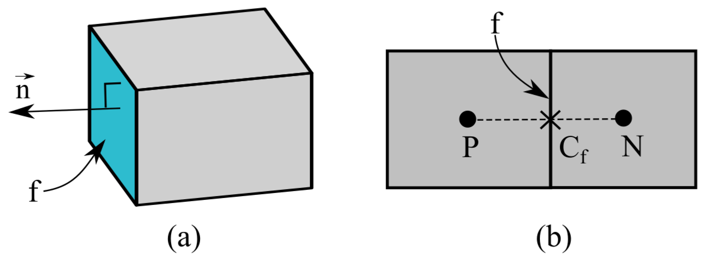
Figure 1. (a) 3D control volume and (b) cell face between current and neighbor cells.
Water 16 00189 g001
Figure 2. Mesh arrangement for the immersed boundary cut-cell method (Shaded area shows the merge of fluid boundary cell and free volume of cut boundary cell).
Water 16 00189 g002
Figure 3. Plan view of the experimental setup of Kleefsman et al. [15]. All dimensions in meters.
Water 16 00189 g003
Figure 4. Comparison of calculated and measured water levels in the experiment of Kleefsman et al. [15].
Water 16 00189 g004
Figure 5. Comparison of calculated and measured pressures for the experiment of Kleefsman et al. [15].
Water 16 00189 g005
Figure 6. Experimental setup: (a) side view; (b) plan view (unit: m).
Water 16 00189 g006
Figure 7. Comparison of hydrodynamic forces measured and calculated on a box in a closed tank.
Water 16 00189 g007
Figure 8. Influence of mesh resolution to hydrodynamic force for the experiment of Arnason [11] with an upstream water depth of 0.25 m.
Water 16 00189 g008
Figure 9. Side view of the wave flume depicting wave gauge placement and bridge location used in the experiments of Istrati [9].
Water 16 00189 g009
Figure 10. Side view of the bridge model [89].
Water 16 00189 g010
Figure 11. Computational domain for the large-scale tsunami experiments (not to scale in x and z directions).
Water 16 00189 g011
Figure 12. Simplified bridge model for numerical simulation (all dimensions in meters).
Water 16 00189 g012
Figure 13. Comparison of calculated and measured water surfaces for the solitary wave of H = 0.42 m.
Water 16 00189 g013
Figure 14. Contour maps of the simulated resultant flow velocity as the solitary wave of H = 0.42 m hits the bridge model: (a) t = 12.8 s, (b) t = 13.3 s, (c) t = 13.8 s, and (d) t = 14.3 s.
Water 16 00189 g014
Figure 15. Horizontal restoring forces for bridge configuration ST2 under the solitary waves of (a) H = 0.42 m and (b) H = 0.55 m.
Water 16 00189 g015
Figure 16. Horizontal restoring forces for bridge configuration ST5 under the solitary waves of (a) H = 0.7 m and (b) H = 0.9 m.
Water 16 00189 g016
Figure 17. (a) Calculated horizontal hydrodynamic force and (b) restoring force on bridge configuration ST2 under a solitary wave of H = 0.42 m.
Water 16 00189 g017
Figure 18. Calculated horizontal velocity of bridge configuration ST2 with different natural frequencies under a solitary wave of H = 0.42 m.
Water 16 00189 g018
Figure 19. Restoring forces calculated by using fully coupled and uncoupled models under a solitary wave of H = 0.42 m on structure ST2 with natural frequencies of (a) 18.5 Hz and (b) 4 Hz.
Water 16 00189 g019
Figure 20. Restoring forces calculated by fully coupled and uncoupled models for bridge configuration ST5 under a bore of H = 0.9 m.
Water 16 00189 g020
Disclaimer/Publisher’s Note: The statements, opinions and data contained in all publications are solely those of the individual author(s) and contributor(s) and not of MDPI and/or the editor(s). MDPI and/or the editor(s) disclaim responsibility for any injury to people or property resulting from any ideas, methods, instructions or products referred to in the content.