Article

Numerical Simulation of Confluence Flow in a Degraded Bed

Department of Civil Engineering, University of Ottawa, Ottawa, ON K1N 6N5, Canada
*
Author to whom correspondence should be addressed.
Water 2024, 16(1), 85; https://doi.org/10.3390/w16010085
Submission received: 2 December 2023 / Revised: 21 December 2023 / Accepted: 22 December 2023 / Published: 25 December 2023
(This article belongs to the Special Issue Advances in Hydraulic and Water Resources Research)

Abstract

:
The fluid dynamics of channel confluences are highly complex due to flow separation and secondary currents. Although numerous studies in the past few decades have focused on the numerical simulation of confluence flow, deformed beds were rarely used. This study attempts to address this issue through numerical simulation of the flow behavior in an open-channel confluence flume with an equilibrium degraded bed in OpenFOAM (version 6.0) to compare the results with a flatbed. In the present study, different turbulence models, including Reynolds-Averaged Navier–Stokes (RANS), large-eddy simulation (LES), and detached eddy simulation (DES) models were performed using rigid-lid and volume-of-fluid (VoF) methods. The accuracy of the models was statistically analyzed by comparing them with observation data. The results demonstrated that the LES model had the best performance, with a minimum average normalized root-mean-square error (NRMSE) of 3% under the VoF assumption. The investigation also further illuminated the intricate interplay of vortical structures within the confluence zone. Notably, the number and behavior of vortices were found to be influenced by channel geometry and size, as well as interactions between separated shear layers. Circulation within the separation zone near the inner bank differed in rotation between the degraded and flatbed cases.

1. Introduction

Confluences are characterized by the convergence of two or more flows and distinguished by complex flow structure, hydraulic geometry, and sediment transport. Such complexity has led researchers to neglect interactions between flows, sediment, and bed morphology at confluences [1]. The conceptual model of the flow structure in a confluence was first developed by [2] (Figure 1); his laboratory research laid the framework for determining the vital governing elements of bed geomorphology (junction angle and discharge ratio) associated with flow structure at confluences. Flow structure at such confluences is typically composed of six different flow zones including the following: (1) stagnation zone near the upstream junction corner, (2) deflection region, (3) separation zone below the downstream junction corner, (4) flow recovery zone at the downstream of the confluence, (5) acceleration zone as the flow enters the downstream, and (6) shear layer between the confluent flows. Several principal factors including junction angle, discharge or momentum ratio, bed level (accordant or discordant), channel geometry, and any differences in density between the incoming flows can affect the confluence morphodynamics [3,4,5,6].
Because these factors substantially impact bed morphology at channel junctions, a comprehensive understanding of the hydro-morphodynamics of channel confluences requires comprehending interactions between the flow and bed morphology. With the advancement of measuring devices and computer technology, it is now possible to capture precisely and describe the three-dimensional flow structure, material movement, bed evolution, and biological and environmental implications at river confluences. Consequently, recent years have seen an increase in the number of studies on river confluences and a diversification of study approaches, including laboratory experiments [7,8,9], field experiments [10,11,12], and numerical simulation [13,14,15].
However, due to the limitations of physical models (associated with scale effects) and field studies (labor- and time-consuming), as well as their dependency on the accuracy of measuring techniques, it is desirable to develop numerical simulation techniques to reduce the costs. Turbulent flows are calculated using a variety of approaches. Those approaches either calculate the turbulent flow directly (Direct Numerical Simulation, or DNS in short) or indirectly. The indirect modelling approach that has relatively low computation cost is to employ Reynolds-averaged Navier–Stokes (RANS) equations with suitable models for turbulent quantities [16]. Other indirect approaches include large-eddy simulation (LES), in which one computes time-varying flow, but subgrid-scale motions are modelled with a turbulence model. A wall function may be used if the grid does not resolve the viscous sublayer. Alternatively, detached eddy simulation (DES) employs a RANS model near the wall’s boundary and applies LES to capture the time-dependent flow away from edges. The separation of the two is characterized by the grid size. The advantage of this method is that it can significantly reduce the computational cost compared to an LES approach. Recently, several studies have utilized numerical simulations to investigate flow behavior in open-channel junctions, as will be reviewed in three subsections below.

1.1. RANS Simulations

Bradbrook et al. (2000) [14] simulated confluence flow patterns, and the results were assessed qualitatively. A variety of parameters such as momentum flux ratio, cross-sectional area, and the density differences between incoming flows were studied to find out their effects on thermal mixing at a small stream confluence. It was shown that the combination of the three parameters affects the rates and patterns of thermal mixing. Bradbrook et al. used renormalization group-based (RNG) and standard k- ε turbulence models to specify velocity field, secondary currents, and time-averaged pressure in channel confluences. Simulations of idealized laboratory-style channels demonstrated that a symmetrical confluence produced two counter-rotating secondary flows on either side of the shear layer; however, in the case of an asymmetrical junction, there was only one cell on the side of the curved tributary.
Huang et al. (2002) [17] used the experimental data from Shumate (1998) [18] and set up a 3D numerical model with two different flow conditions for a channel junction with a 90° angle to study open-channel confluence flow. RANS equations with k-ω turbulence model were the governing equations under the assumptions of incompressible and steady-state flow. The 3D model was demonstrated to successfully reproduce hydrodynamic characteristics of the junction flow. The separation zone was situated along the left bank of the main channel immediately following the junction and was smaller, closer to the channel bed than near the water surface. Also, as the junction angle increased, the separation zone size and strength grew larger.
Shakibania et al. (2010) [19] used SSIM2.0 for a comprehensive 3D numerical study of secondary circulation, flow in the separation zone, velocity field, and water level in different flow conditions with varying discharge ratios, junction angles, and Froude numbers. It was concluded that flow structure at channel confluences is greatly impacted by the secondary flow. The secondary flows emerged in roughly three counter-rotating helical cells across the section immediately following the junction. The first helical cell formed in the separation zone, and because silt is deposited here, this type of cell may disappear in natural rivers. Due to the deflection of the tributary flow in the direction of the main channel, the second helical cell developed. These cells are thought to be the strongest in the confluence and gradually weaken downstream of the main channel. Due to the interaction of the second cell and the flow of the main channel, the third helical cell appeared within the main channel flow with rotation counter to that of the second cell (see Figure 7 in [19]).
Similarly, Song et al. (2012) [20] performed 3D simulations of secondary flow in confluent and curved channels. The equations of depth-averaged shallow water together with dispersion stresses were solved by the SU/PG scheme. They used Shumate (1998) [18] experimental data to validate the proposed model. The computed values of the depth-averaged velocity and the water surface profile over the channel revealed good comparison with laboratory data, which indicated that secondary velocity profiles were appropriately preserved. They demonstrated that two counter-rotating cells are produced downstream of the junction, one from the main river and the other from the branch river. Due to the fluid’s viscosity, they rotate against each other and eventually dissipate as they move downstream.
Shaheed et al. (2019) [21] conducted a 3D numerical simulation model in an open-source software, “OpenFOAM,” to simulate secondary currents in open-channel confluences. The behavior of these currents was simulated by using the finite volume method (FVM). They employed standard “k-ε” and “realizable k-ε” turbulence models, and their results indicated that the “realizable k-ε” model had better performance.
Tang et al. (2018) [22] developed another 3-D numerical model based on the RANS and Reynolds Stress Turbulence model to model flow patterns and contaminant transport with different bed morphologies. In their study, the effects of bed morphology on the hydrodynamics and the transport of contaminants on degraded beds at 90-degree channel confluences were investigated, and the results were validated by experimental data. The results show that the shear layer and two counter-rotating helical cells controlled the distribution of contaminant, which are affected by the discharge ratio and the bed morphology.
Penna et al. (2018) [23] simulated ten confluence angles ranging from 45 to 90 degrees to examine the effects of confluence angle on flow structure. The Reynolds-averaged Navier–Stokes (RANS) equations in three dimensions were solved using a computational method incorporating a k-ε turbulence closure model. The results suggested that an increase in the confluence angle produced a broader and longer retardation zone at the upstream junction and separation zone. As the angle of confluence increases, so does the flow deflection at the entrance of the tributary to the main channel. However, the confluence angle does not necessarily increase the more significant streamwise velocity.

1.2. LES Simulations

Schindfessel et al. (2017) [24] investigated the effect of various cross-sectional formations on the separation zone in a sharp-edged open-channel confluence. Four distinct cross-sectional shapes were analyzed using a large-eddy simulation (LES) model. There was a considerable variance in the separation zone dimensions for non-rectangular geometries due to lateral currents that may diminish the local momentum deficit.
Le et al. (2019) [25] employed LES to inspect the hydrodynamics of a natural confluence zone in the Mississippi River. Data from remote sensing (light detection and ranging; LiDAR) and field measurements were used to construct the digital elevation model. The LES results were used to gain more insight on the river flow dynamics and to illustrate the long-range impacts of hydraulic structures on the downstream flow. This study demonstrated the feasibility of high-resolution LES for large-scale rivers by considering the detailed bathymetry and submerged hydraulic structures.
Ramos et al. (2019) [26] used the experimental data collected by Yuan et al. (2016) [27] to develop a numerical model in OpenFOAM. In this study, flow ratio and downstream Froude number of two geometries were compared with experimental results by Yuan (2016) [26] in a flume with a wider downstream than the upstream main and tributary channels. The focus of this study was downstream of the channel junction, and the LES results were used to examine the downstream channel width influence on turbulent flow features. Extension of the downstream channel turns out to decrease the backwater effects, the flow contraction, and the associated water surface depression. Furthermore, the three-dimensionality of the separation zone in the mean flow is enhanced due to complex flow patterns, resulting in a reduced width and length of the recirculation zone in the lowest third of the water column.
Turbulence flow behavior through a rectangular confluence channel was also investigated by Herrera-Granados (2021) [28] and laboratory records were compared with the simulation results of LES and RANS models. The model output was in good agreement with time-averaged factors but was not sufficient for the proper estimation of the turbulence quantities.
Duguay et al. (2022) [29] used an LES model in OpenFOAM and resolved three categories of large-scale turbulent structures, namely (1) vertically oriented (Kelvin–Helmholtz) vortices; (2) secondary flow helical cells, and (3) smaller, strongly coherent streamwise-oriented vortices. Intricate interactions among divided flow over the scour hole’s avalanche face, upwelling tributary flow, as well as downwelling main channel flow were the main causes for the mixing at this asymmetric mesoscale fluvial confluence. To create a stronger mixing, both vertically oriented and streamwise-oriented vortices were firmly coupled. It is worthy to note that similar interactions were predicted via collective analysis of instant eddy-resolved modelling and aerial studies of turbulent mixing of natural turbidity gradients within the mixing interface.

1.3. DES Simulations

Constantinescu et al. (2011) [30] employed an eddy-resolving DES numerical model at an asymmetrical river junction with a concordant bed to model the mean flow and large-scale turbulence structure. The simulation targeted a confluence with a momentum ratio between the two incoming streams close to one. The results of the simulation implied that the quasi-two-dimensional eddies were dominant in the mixing interface.
Horna-Munoz et al. (2020) [13] studied the effects of density differences between incoming flows at a small, concordant bed in a natural river confluence. The simulation was carried out using a DES model. The predicted flow patterns demonstrated that secondary flow increased with increasing distance from the confluence junction.
Cheng and Constantinescu (2020) [6] used the DES model to investigate the effects of stratification caused by density variations between two incoming flows using a confluence in a medium-sized stream and a highly discordant bed.
Jiang et al. (2022) [15] investigated flow hydrodynamics and mixing at the asymmetric confluence of the Yangtze River and the Poyang Lake channel using eddy-resolving numerical approaches. The result revealed that the flow hydrodynamics and mixing processes at the large (W/D > 50) confluence shared many similarities with those typically observed at small natural confluences with a concordant bed, as well as some significant differences.
In order to numerically model the hydrodynamics of river confluences, the turbulence closure and the water surface treatment should be chosen carefully. Whereas numerous studies in the past few decades have focused on the simulation of confluences (Table 1), to the best of the authors’ knowledge, no deformed beds have been examined by comparison of simulations performed using a wide range of different turbulence models, namely RANS (standard k–ε, realizable k–ε, k-ω SST, V2-f), LES, and DES with two free-surface methods (rigid lid and VOF).
Hence, the main objective of this study is to implement these simulation techniques to model the flow field of a confluence with a degraded bed and determine the accuracy of the results to investigate the effect of bed morphology on secondary currents. To achieve this goal, first a degraded bed case studied experimentally by Yu et al. (2020) [33] was simulated to validate the numerical models. Then, the most accurate simulation was selected, and the degraded bed was replaced by flatbed to investigate the effect of differences in bed morphology on confluence hydrodynamics; specifically, the impacts on flow deflections, separation zone, and secondary flow.

2. Numerical Methodology and Model Verification

2.1. Numerical Framework

Computational fluid dynamics (CFD) is a valuable tool for uncovering potential small-scale flow phenomena under different hydrodynamic conditions [34]. OpenFOAM version 6.0, an open-source CFD application, was utilized to conduct the numerical simulations in the present investigation. This toolkit provides a flexible and configurable framework for solving the governing equations for a viscous, incompressible flow. RANS, LES, and DES were used in this study to model the turbulent nature of these flows. OpenFOAM’s finite volume approach is founded on a structured mesh with non-uniform distribution. Each control volume’s dynamic attributes are defined by its centroid. The mesh supports an unlimited number of control volume points per face. In the numerical analysis, divergence is calculated using the Van Leer method, Laplacian terms are calculated using a corrected Gauss linear scheme, and interpolation is performed using a linear approach. This analysis uses an adjustable time increment, which means that each time step is determined depending on the previous time step in order to maximize accuracy; nevertheless, this method increases computing cost and time.
To solve the governing equations, the “interFoam” and “pimpleFoam” solvers of OpenFOAM were used to compare a combination of the finite volume method with either the volume of fluid (VOF) or the rigid-lid method for free-surface simulations. InterFoam can solve problems with dynamic mesh. In this solver, the pressure correction algorithm PIMPLE (which constructs a nonlinear set of equations and solves them using an iterative approach) was used to track the fluid flow, while the VOF method was utilized to track the free surface. PISO (pressure implicit with splitting of operator) and SIMPLE (semi-implicit method for pressure-linked equations) are combined to form the PIMPLE algorithm. The PISO and PIMPLE methods are suited for transient situations, while the SIMPLE approach is used for steady-state problems. They are, however, all iterative problem solvers. First-order Euler scheme was used to discretize the temporal term, while the Gauss linear method was employed for the gradient term. Corrected Gauss linear method was applied for the Laplacian. In addition, a Gauss Van Leer plus Gauss linear scheme was used to define the divergence terms, and a linear scheme was used to discretize the interpolation term. Every individual variable was assigned certain tolerance levels. As a result, the desired convergence was anticipated to take place during the iteration. The level of accuracy was defined as 10−5 for the fraction of liquid ( α ) and 10−8 for pressure and velocity in the Gauss–Seidel method for solving the resulting linear system of equations.

2.2. Hydraulic Conditions

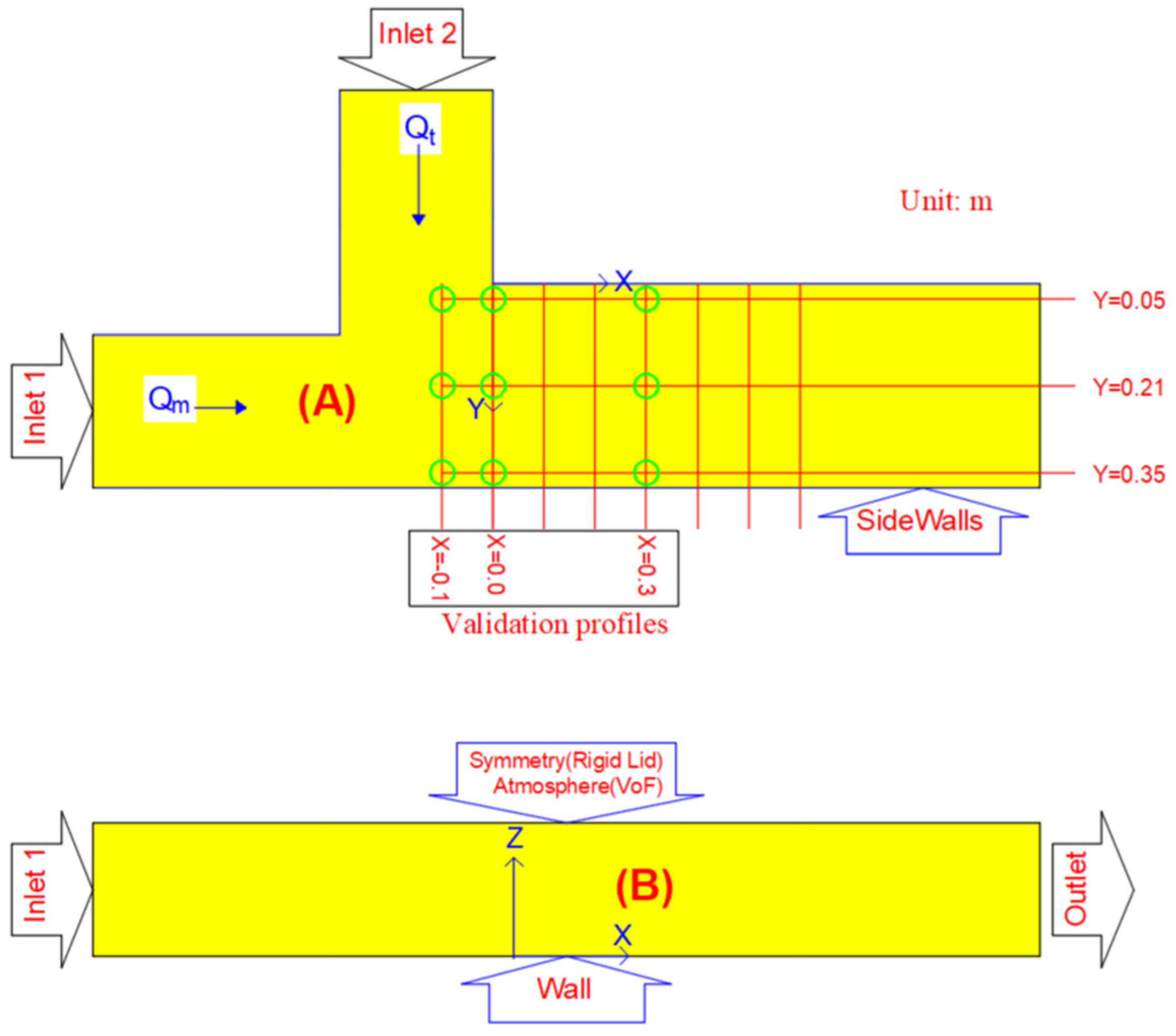
The experimental case used for validating the numerical approaches was previously described by Yu et al. (2020) [33]. This work examined confluence morphodynamics as well as deposition patterns of contaminated sediments. The dimensions of the flume were 40 cm (height) with different widths for the upstream (30 cm) and downstream (40 cm) channels (Figure 2). Two pumps with the same fixed flow rate (30 L/s) were deployed. The flow discharge in each channel was measured by ultrasonic flowmeters and could be altered using valves. A weir gate was installed at the downstream end of the flume to adjust the flow depth throughout the flume. An equilibrium degraded channel bed was established for the given flow regime, and then the bed was fixed to enable flow velocimetry and subsequent contaminated sediment feeding experiments. For further investigation through numerical simulations, the equilibrium degraded bed was initially transformed into a flatbed, and the outcomes of this alteration were thoroughly examined. The implications of this alteration are discussed in subsequent parts of this paper. In the present paper, the test scenario of a 90° channel confluence with a discharge ratio of RQ = 1.5 was utilized where RQ = Qt/Qm with Qt and Qm being the discharges of the upstream tributary channel and main of the open channel, respectively. Consequently, the discharge ratio was identical for all cases and shared the same Froude and Reynolds (Re) numbers, as shown in Table 2.

2.3. Mesh Generation

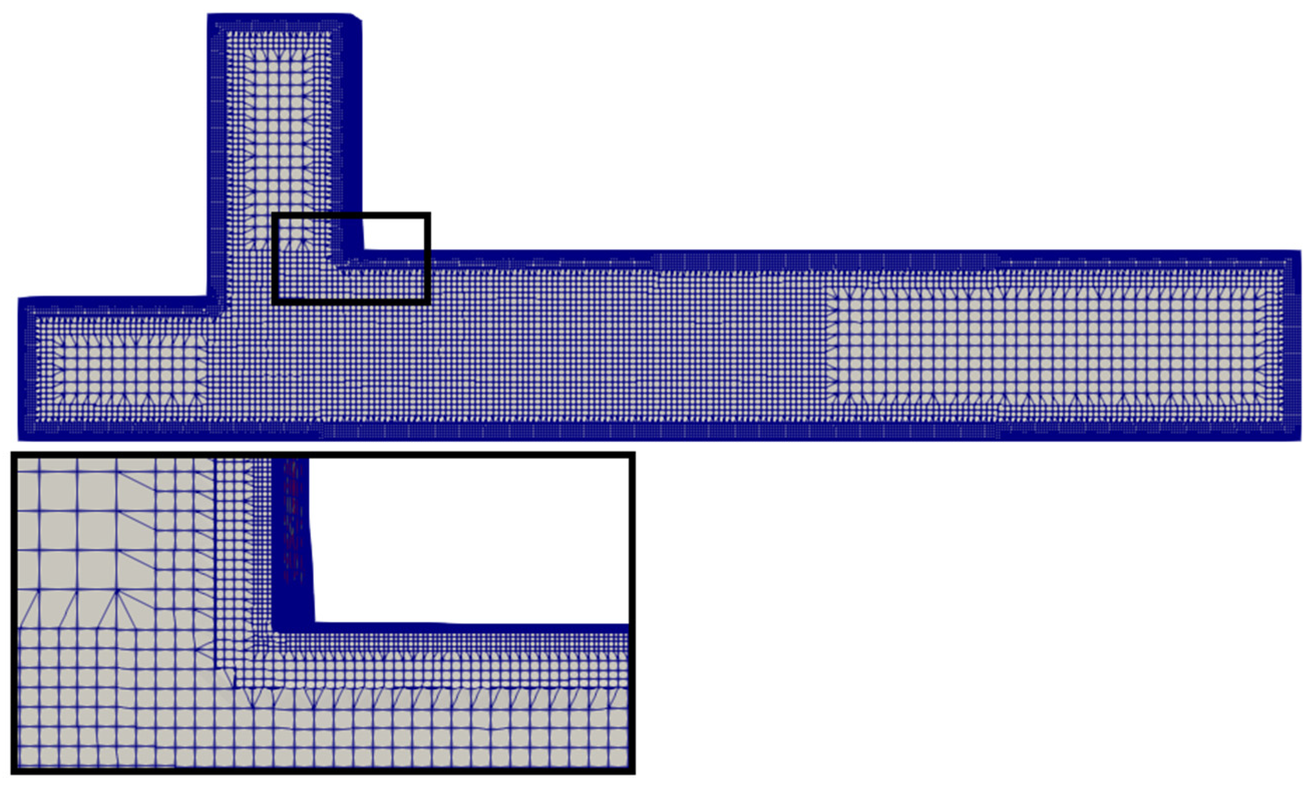
In this study, snappyHexMesh was used to generate the mesh, which is shown in Figure 3. The size of the numerical domain is the same as the physical field of the experiment [33]. The grid size gradually increases from each boundary since a smooth grid transition is essential to make the numerical calculation stable (Figure 3).
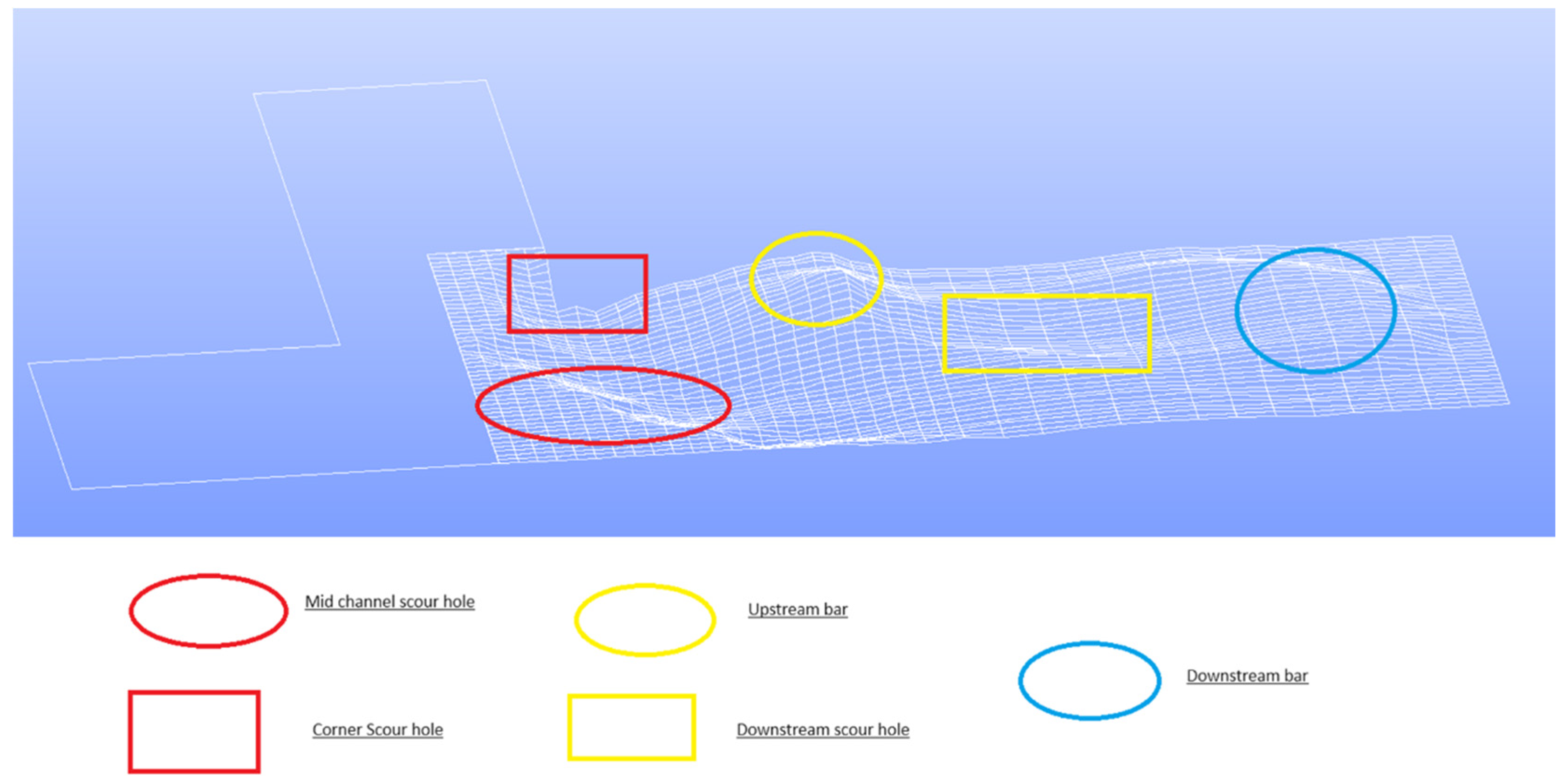
The geometry of the channel was created using Salome platform. A total of 2000 points were defined to create the degraded bed as opposed to the flatbeds that require a drastically lower number of points (i.e., 8 points). A Salome-generated bed surface map in this model is demonstrated in Figure 4.

2.4. Boundary Conditions

To achieve accurate simulation, different boundary conditions were employed, as illustrated in Figure 2. Hydraulically standard wall functions were employed which include four different boundaries: the two inlets and one outlet of the channel, the walls (including side walls and bottom), and the surface of the flow (symmetry for rigid lid and atmosphere for VoF). Water discharge was specified at the inlets. Zero-gradient condition was considered at the outlet.

2.4.1. Wall Function Boundaries

Turbulence and velocity parameters are required in the cell closest to the wall because there is typically insufficient cell spacing near solid borders to resolve the laminar sublayer. The “universal” law of the wall, which is based on shear velocity, is usually utilized. The fundamental presumptions of this law rely on the existence of a local turbulence equilibrium, which is unstable in the presence of flow separation. Consequently, the non-equilibrium version of the law of the wall [35] may be applied, which uses the square root of the turbulent kinetic energy as the characteristic velocity scale [36].
The “universal” law is as follows:
U r U τ = ln ( E Υ + ) κ
with U τ = τ / ρ and Υ + = U τ Υ μ where U r is the velocity parallel to the wall, U τ is the shear velocity, τ is the bed shear stress, E is the roughness parameter, Υ + is the nondimensional wall distance, Υ is the normal distance to the wall, μ is the fluid kinematic viscosity, and κ is the von Karman constant (0.4). Launder and Spalding (1983) [35] can be used to connect the shear velocity to the local kinetic energy under the assumption that there is a local equilibrium of turbulence:
k = U τ 2 c μ
The boundary condition for ε is given by:
ε = ( c μ ) 3 / 4 k 3 / 2 κ Υ
Because the assumption of local equilibrium (Equation (2)) does not hold in the presence of separation, k is employed in the non-equilibrium wall function, as shown below by Shaheed et al. (2021) [37]:
U r k U τ 2 = l n ( 0.25 c μ E k Υ ) 0.25 c μ κ
where k is taken from the transport equation.

2.4.2. Free Surface

Due to surface depression and elevation, which are characteristics of confluence flow dynamics [38,39], the free surface in the model must be simulated. Because identifying the exact contours of the free-surface elevation is challenging, the assumption of a “rigid lid” has been commonly employed in prior publications, which viewed the surface as a plane. Regarding the symmetry plane, all surface normal derivatives are set to zero. If the surface is not fixed, a change in water depth may occur, reflected by the surface pressure, which is not set to zero. Therefore, a pressure greater than zero signifies superelevation, and a pressure less than zero represents surface depression. This means that the pressure gradient term in the momentum equations considers the variance in the position of the water surface. In contrast, it is not considered in the mass continuity equation, which could lead to predictions of maximum velocity in areas of superelevation [39] and the opposite in areas of surface depression. Another strategy is based on free-surface capturing (e.g., the volume of fluid method), which simulates the location of the free surface. Free-surface capturing methods are typically more accurate than rigid-lid methods [37].

2.4.3. Bed Morphology

Figure 4 demonstrates the degraded bed morphology with the bed area possessing a wide range of elevations with zones of erosion and deposition. From the downstream corner to the outer bank, a massive, curving scour hole developed. Intriguingly, based on observations made during the development of the bed, the curving scour hole was initially comprised of two independent scour holes that progressively joined in the middle of the channel. One of these two scour holes was round and placed at the downstream corner of the junction (the solid red rectangle); we will refer to it as the “corner scour hole”. The scour hole that was roughly centered in the channel (the solid red circle) will be referred to as the “midchannel scour hole”. Between the upstream and downstream bars (the red dashed circle), a second, shallower scour hole formed; it will be referred to as the “downstream scour hole”. In addition, a conical bar formed near the downstream junction but was not connected to it (the solid cyan circle). It will henceforth be referred to as the “upstream bar”. A bar in the shape of a fan was created at the flow recovery zone (the cyan dashed circle), which will henceforth be referred to as the “downstream bar” [33].

2.5. Flow Visulazation

Flow visualization, in essence, accomplishes something extraordinary: it renders visible complex processes that would otherwise remain hidden from the naked eye [40]. ParaView version 5.11.0 played a pivotal role in our CFD simulations as a versatile tool for post-processing and visualizing the results generated by OpenFOAM. Leveraging ParaView’s capabilities, we conducted comprehensive flow visualization, examining intricate details such as flow fields, contours, and streamlines. The interactive features of ParaView version 5.11.0, facilitated dynamic exploration of 3D visualizations, enabling to zoom in on specific regions of interest and manipulate data for in-depth analysis. Additionally, ParaView served as a valuable platform for data analysis tasks, including the extraction of quantitative information, generation of plots, and performance of statistical analyses on simulation results.

2.6. Model Verification

2.6.1. Determination of Solution

The Free-Surface Model is used in open-channel flow, while the Rigid Lid is used in closed channel flow. In the Free-Surface Model, both air and water flows are considered in the simulation, which allows for a deformed interface, while in the Rigid-Lid Model, only the water flow is considered. InterFoam solver is used in this study, which is usually utilized for incompressible and turbulent flows in the cases of open channels (also referred to as the Free-Surface Model). The free water surface was simulated using the volume of fluid (VOF) method. Also, pimpleFoam solver is used, and the numerical treatment was performed by means of a flat rigid lid, in which the free surface was treated as a flat, horizontal, and frictionless rigid lid at the top boundary. For discussion on the rigid-lid approach in other flow cases, see Constantinescu et al. (2012) [41].

2.6.2. Governing Equations

Reynolds-Averaged Navier–Stokes (RANS) Equations

Fluid-related problems may be simulated using Reynolds-averaged Navier–Stokes (RANS) equations which take the following form for the case of incompressible flow:
u ¯ i t + u ¯ j u ¯ i x j = 1 ρ p ¯ x i + x j ϑ u ¯ i x j + u ¯ j x i x j ( u i u j ¯ ) + g i
And continuity equation:
u ¯ i x i = 0
where ρ = density of the fluid; p = pressure; ui = mean velocity in the i-direction, i = x, y, z, which refer to the streamwise, cross-stream, and vertical directions, respectively; u i represents the corresponding fluctuating components; t is time; υ is the kinematic viscosity of the fluid, u i u j ¯ are the time-averaged turbulent Reynolds shear stresses, and g is the gravitational acceleration. The flow properties have been disintegrated into their mean and fluctuating components and integrated over time (i.e., time-averaged). Dependent variables are a function of both space coordinates and time. For general 3D turbulent flows, there are four equations including the continuity equation. In theory, these would be enough equations to solve all three velocity components and the pressure, but there are six more unknowns: the Reynolds stresses, u i u j to represent turbulent effects. So, the Reynolds stresses must be modeled to complete the equations.
Several models have been developed to resolve the distribution of eddy viscosity over the flow field. Eddy viscosity is typically used to model the turbulent effects lost in averaging in a computational fluid dynamic (CFD) simulation. The model addresses the dissipation of energy which was neglected due to the turbulence. Turbulence models allow the calculation of the mean flow prior to calculating the time-dependent flow field for the different levels of complexity of flows and computational cost. During the past four decades, two-equation models (e.g., k-epsilon and k-omega) have served as the foundation for modelling eddy viscosity in RANS [42]. Two-equation turbulence models enable both turbulent length and time scales to be determined based on Boussinesq’s assumption (i.e., the turbulence stress is modelled as a function of the velocity gradients and the eddy viscosity).

Large-Eddy Simulation (LES) Models

In these models, eddies are categorized by their size based on the local grid spacing. Large eddies are computed directly by solving the Navier–Stokes (NS) equations, while small eddies are calculated with a subgrid model based on the Boussinesq theory. The spatial filter is employed to disintegrate velocities into two parts: the resolved parts ( U ~ , which captures eddies larger than the filter width) and residual parts ( u ′, fluctuation velocity of small eddies modeled in subgrid) [43], and ui = mean velocity in the i-direction (I = x, y, z). The filter width is related to the cell volume. Particularly, the filter width needs to be defined in a way that captures the smallest eddies of interest.
u x , t = U ~ x , t + u x , t = u ¯ i + u i
u i : Fluctuating velocity in tensor notation
u ¯ i x , t = G ( x ξ ; Δ ) u i ( ζ , t ) d 3 ζ
where spatial filter ( G ) is defined as follows:
x ζ ; Δ = 1 Δ 3 if   x i ζ i < Δ x i 2 0   otherwise
And the first filter is defined as: = ( x y z ) 1 3 .
∆: Cut-off width in LES models.
After applying the spatial filter, the filtered NS equations are:
u ¯ i x i = 0
ρ u ¯ i t + ρ ( u i u j ¯ ) x j = p x i + x j [ μ u ¯ i x j + u ¯ j x i ]
The interactions between large-scale filtered eddies u ¯ i and the Sub Grid-Scale (SGS)-modeled eddies u lead to the nonlinear term u i u j ¯ , written as:
u i u j ¯ = u ¯ i u ¯ j + u i u j ¯ + u i u j ¯ + u i u j ¯ = u ¯ i u ¯ j τ i j S G S
After substitution, the filtered NS equation can be expressed as:
ρ u ~ i t + ρ u j ~ ( u i ~ ) x j = p ~ x i + τ i j ~ x j ρ τ i j S G S x j
u ~ i : Favre-averaged velocity in tensor notation.
The Navier–Stokes equations are averaged over the cell volume (Schumann, 1975) [44] and, as with Reynolds averaging, produce unknown stresses related to SGS motion. These stresses ( τ i j ) are given by:
τ i j = 2 ρ ϑ t S i j
where ρ is the fluid density, ϑ t is the eddy viscosity, and S i j is the local mean strain rate:
S i j = 0.5 u i x j + u j x i
The eddy viscosity is determined using a mixing-length relationship:
ϑ t = l 2 ( 2 S i j u i x j ) 1 2
The mixing length, l, is the characteristic length of unresolved eddies, defined as:
l = m i n ( C s h , κ d w a l l )
where Cs is the Smagorinsky constant, κ is the von Karman constant, and d w a l l is the normal distance to the nearest wall, and h is the representative mesh interval:
h = d x 2 + d y 2 + d z 2 3
where dx, dy, and dz are the local mesh dimensions in the three coordinate directions.
Various subgrid-scale (SGS) models, such as the Smagorinsky subgrid-scale model, a dynamic subgrid-scale model, and a stimulated subgrid-scale model, can be employed in Large-Eddy Simulation (LES) to predict flow behavior. The findings indicate that the dynamic and stimulated models exhibited slightly superior performance compared to the Smagorinsky model [45].
Further details of this model can be found in [31,46].

Detached Eddy Simulation (DES) Models

The best performance in the RANS model was observed in the near-wall region. However, the LES model showed its best performance anywhere in the simulation area except the near-wall region. The DES model employs the specification of both RANS and LES approaches, leading to a potentially more accurate model. The large-scale turbulent flow structures are typically addressed by the LES model [47]. It has been proven that the DES approach is more economical in computational costs while generating highly accurate results [48,49].
The turbulence specific dissipation rate equation is as follows:
D ν ~ D t = c b 1 S ~ ν ~ + 1 σ . ν + ν ~ ν ~ + c b 2 ν ~ ) 2 c ω 1 f ω [ ν ~ d ] 2
where ν ~ is the working variable,
S ~ S + ( ν ~ κ 2 d 2 ) f υ 2 ,   f υ 2 = 1 χ / ( 1 + χ f υ 1 )
and S is the magnitude of the vorticity. The eddy viscosity ϑ t is obtained from
ϑ t = ν ~ f υ 1 ,   f υ 1 = χ 3 / ( χ 3 + c υ 1 3 ) ,   χ ν ~ υ
where υ is the molecular viscosity. The function f ω is given by
f ω = g [ 1 + c ω 6 g 6 + c ω 6 ] 1 / 6 ,   g = r + c ω 2 ( r 6 r ) ,   r ν ~ S ~ κ 2 d 2
For further details and values of the coefficients, the reader may refer to Constantinescu et al. (2003) [50].

2.6.3. Wall-Normal Distance of First Grid Cell

Large Reynolds numbers of the confluence model make it computationally impractical to place the near-wall grid point within one wall unit (Y+) from solid boundaries, where
Y + = Y u τ ν
and uτ is the friction velocity, Y is the absolute distance from the wall, and ν is the kinematic viscosity. However, wall model LES (WMLES), i.e., LES with wall functions, overcomes this requirement by identifying the primary grid point within the log-law region (30 < z+ < 500). Although details of near-bed turbulence are not obtained, the wall-modelled approach has been widely applied to investigate large-scale turbulent phenomena within the outer region of the water column in flume and fluvial applications [29]. A velocity-based wall function was employed to ascertain the near-wall turbulent viscosity and bed shear stress caused by the rough solid boundary. This condition was met for all the simulations, with z+ being usually above 30.

2.6.4. Mesh Sensitivity Analysis and Verification of Turbulent Kinetic Energy (TKE)

The meshes used in this study were specified based on the mesh sensitivity and independency analysis and used for the validation described in Section 3. Mesh sensitivity analysis was performed to choose the optimum mesh size, by finding the coarsest mesh size for which velocity results did not differ for a finer mesh (Table 3). The developed model was thus run with three cell numbers of 801,254, 1,004,209 and 1,205,052 for RANS models. It was found that velocity results did not change substantially (around 0.04%) between the 1,004,209 and 1,205,052 meshes; thus, the 1,004,209 mesh was selected for the RANS group. Also, 6,376,502 was chosen for the LES group based on verification of TKE.
Pope (2004) [51] suggested that in order to use LES models effectively, it is important to resolve at least 80% of the TKE (kres) on the mesh. According to Equation (21), over 80% of the cells in both simulations meet this requirement.
K r e s = 1 2 ( u 2 ¯ + v 2 ¯ + w 2 ¯ )
where u , v , and w are the velocity fluctuations in the streamwise, lateral, and vertical directions, respectively, and the overbars represent time-averaging.
Furthermore, it is noteworthy to mention that both skewness and equiangular skew parameters are maintained at a value of zero. This signifies an optimal mesh quality, indicating that the elements within the mesh exhibit a desirable geometric arrangement and distribution. A skew of zero implies that the mesh elements are well-shaped without distortion, while an equiangular skew of zero indicates that the angles between adjacent mesh elements are uniform and evenly distributed. These comprehensive data underscore the high quality and precision of the mesh, ensuring accurate and reliable results in various applications.

3. Results and Discussion

3.1. Model Validation and Comparison

Figure 5, Figure 6, Figure 7, Figure 8, Figure 9 and Figure 10 provide a detailed examination of the time-averaged velocity streamwise component (U) for both LES and DES simulations, as well as the velocity streamwise component for RANS models, at various points along the bed, as indicated by circles in Figure 2. The results of the simulations show a reasonable level of agreement with the experimental data; however, there is room for improvement in some areas closest to the bed. It is suggested that a different approach, such as not using wall functions, may be needed to achieve better results. The study by Yu et al. (2020) [33] does not provide water depth data for further validation of the simulated results.

3.1.1. Velocity

Figure 5, Figure 6, Figure 7, Figure 8, Figure 9 and Figure 10 show the measured and modeled streamwise velocity at 9 profiles where U is the streamwise velocity (m/s) and Z is the elevation above the bottom of the flume (m). The selected profiles were located in the intersection of the main and tributary channel (X = −0.1), near the downstream junction corner (X = 0), and after the junction including the flow separation zone (X = 0.3; Figure 7 and Figure 10).
In general, greater deviations from the experimental data were observed for the rigid-lid simulations (Figure 8, Figure 9 and Figure 10) than the VoF approach (Figure 5, Figure 6 and Figure 7). Under the VoF approach, the streamwise velocities before the junction (X = −0.1) and at the junction (X = 0) were in better agreement with experimental data than after the junction (X = 0.3). This could be due to eddies caused by the merging of the tributary and main flows, which impeded a precise compliance with the data obtained from the experiment. According to [52], the complexity of the flow features in X = 0.3 could be ascribed to the separation/recirculation zone and secondary flow.
At first glance, there appears to be only small differences in predicted flow velocity between the six turbulence models and two different free-surface methods (i.e., VoF and rigid lid). Nevertheless, a statistical analysis is required to reveal their detailed differences. The statistical analysis involved calculation of the root-mean-square error (RMSE) and normalized root-mean-square error (NRMSE) for 6 turbulence models and two flow surface models (see Table 4 and Table 5):
R M S E = ( U e x p e r i m e n t U S i m u l a t i o n ) 2 n
N R M S E = R M S E A v e ( U S i m u l a t i o n )
where n is the number of observation data and U is streamwise velocity.
The LES model provided the lowest average velocity error in both methods (i.e., VoF and rigid lid) compared to the other five turbulence models applied in this study. This model also provided the minimum error percentages in the average value of all the cross sections as well as within most individual sections. This result suggests that the LES model is more reliable for predicting flow velocities in complex flow geometries such as confluent channels than the other five turbulence models. Based on the statistical indicators in Table 4 and Table 5, it can also be concluded that the k-ω SST model is not a viable method to simulate cases with complex geometry.
The average range of the error for the VoF and rigid-lid methods were computed to be 3% to 16% and 15% to 26%, respectively, which shows the reliability of the VoF method in this case. Thus, subsequent flow structure analysis will be presented using the model results under the LES turbulence model and the VoF method. Finally, the error values for the other turbulence models did not follow a consistent trend. It is noteworthy that most of the turbulence models used in this study revealed a reliable error percentage at most profiles except for the profile at X = 0.3, Y = 0.05. This profile was located in the separation zone with small eddies, which makes it more difficult to predict the flow behavior in this zone.
In the comparison between the rigid-lid and VOF approaches for a channel confluence described above, it was shown that the VOF method provides better results than the rigid-lid approach. This is due to the significant role of the free-surface variations in flow structure. In the rigid-lid method, however, water surface is assumed to be constant, and this effect is simulated by an increased surface pressure at the location of superelevation. While this approach can be reasonable to some extent, it is not as accurate as simulation of actual free surface, which is accomplished using the VOF method.

3.1.2. Turbulence Characteristics

Figure 11 and Figure 12 display the TKE profiles from the LES–VOF simulation at six locations along the X = −1 and X = 0.3 plane in the main channel, which has the highest level of turbulence. Despite similarities, some variations can be seen, which could be caused by the less precise temporal resolution of the acoustic Doppler velocimetry measurements in the study by Yu et al. (2020) [12].

3.2. LES Deformed Bed Versus Flatbed

3.2.1. Time-Averaged Longitudinal Velocity Field

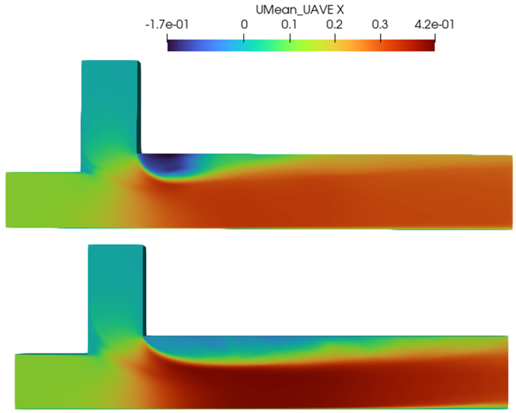
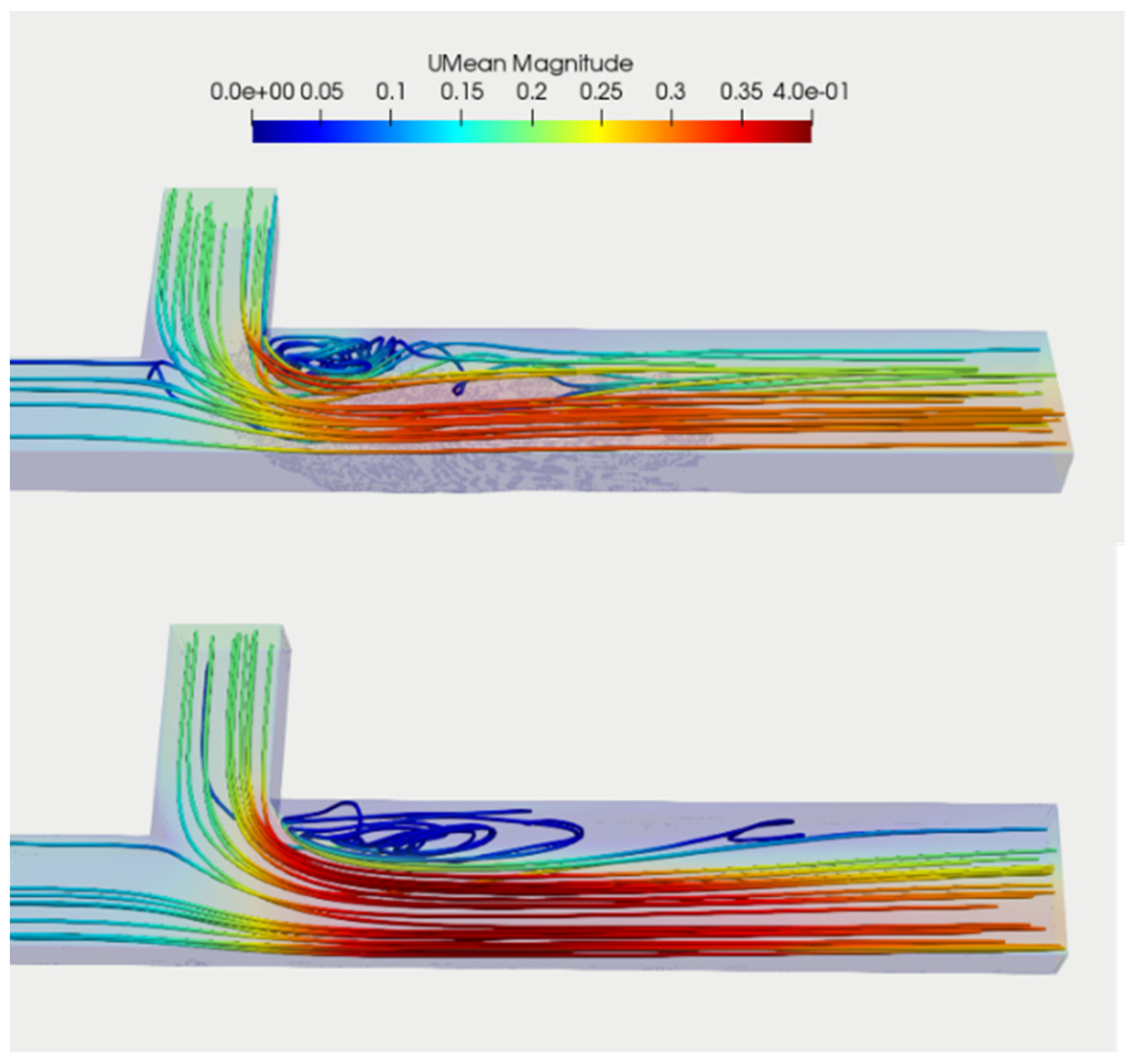
Figure 13 shows the time-averaged surface longitudinal velocity field of the confluent channel surface over 100 time steps after reaching the steady state in the LES model under the VoF approach for flat and degraded morphology, which, as shown above, had the lowest errors of the tested models. As shown in the figure, velocities in the upstream main and tributary channels were relatively low. However, after the intersection of the two channels, the velocity increased and reached the maximum value. The separation zone refers to the region near the wall downstream of channel junctions where the velocity of the flow is reduced. The recirculation within these separation zones is depicted by negative velocities, suggesting a motion against the upstream direction. From Figure 13, it is evident that the separation zone is larger in a flatbed compared to a degraded bed. The highest velocities are observed immediately after the junction in the primary flow region of the main channel, which is constricted by the presence of the separation zone. The maximum velocity moved from the junction towards the outer bank of the downstream main channel. In cases of a degraded bed, the reduction in maximum velocity may be attributed to the enlargement of the constricted section caused by scour.
Figure 14 shows the distribution of time-averaged longitudinal velocity after reaching the steady state at X = 0.2 for degraded and flatbeds. The velocity patterns differ between the near-surface and near-bed regions, especially when the bed is degraded. Near the surface, the separation zone is larger in terms of length and width, which varies from top to bottom due to the angle at which the branch channel flow enters. There is also increased recirculation within the separation zone near the surface, which will be explained in more detail later.

3.2.2. Streamlines

Figure 15 presents an illustration of the flow patterns observed in a confluence zone. The figure displays streamline of the simulated time-averaged velocity fields, which indicate an increase in flow velocity towards the downstream confluence for both the flatbed and degraded bed scenarios. The flow streamlines were based on averaging 100-time steps of the LES model under the VoF approach, processed using ParaView (version 5.11.0). In the flatbed case, the flow separates at the corner and forms a recirculation zone, while in the degraded bed case, the streamlines are concentrated in the scour hole and guided upstream by the depositional bar, resulting in a smaller recirculation zone. Furthermore, the streamlines are color-coded based on the streamwise velocity component, revealing that there is less contraction of the main channel flow in the degraded bed case next to the separation zone. Also, while the flow streamlines in the upstream were mostly parallel, as the flow approached the junction, the streamlines tended to be concentrical, creating strong flow curvature in the confluence. Rotating flow at the corner of the junction, which occurred due to the separation zone, is also illustrated in this figure. The results of the simulation indicated the capability of the LES model to predict both flow curvature in the confluence and recirculation in the separation zone.

3.2.3. v-w Vector Characteristics

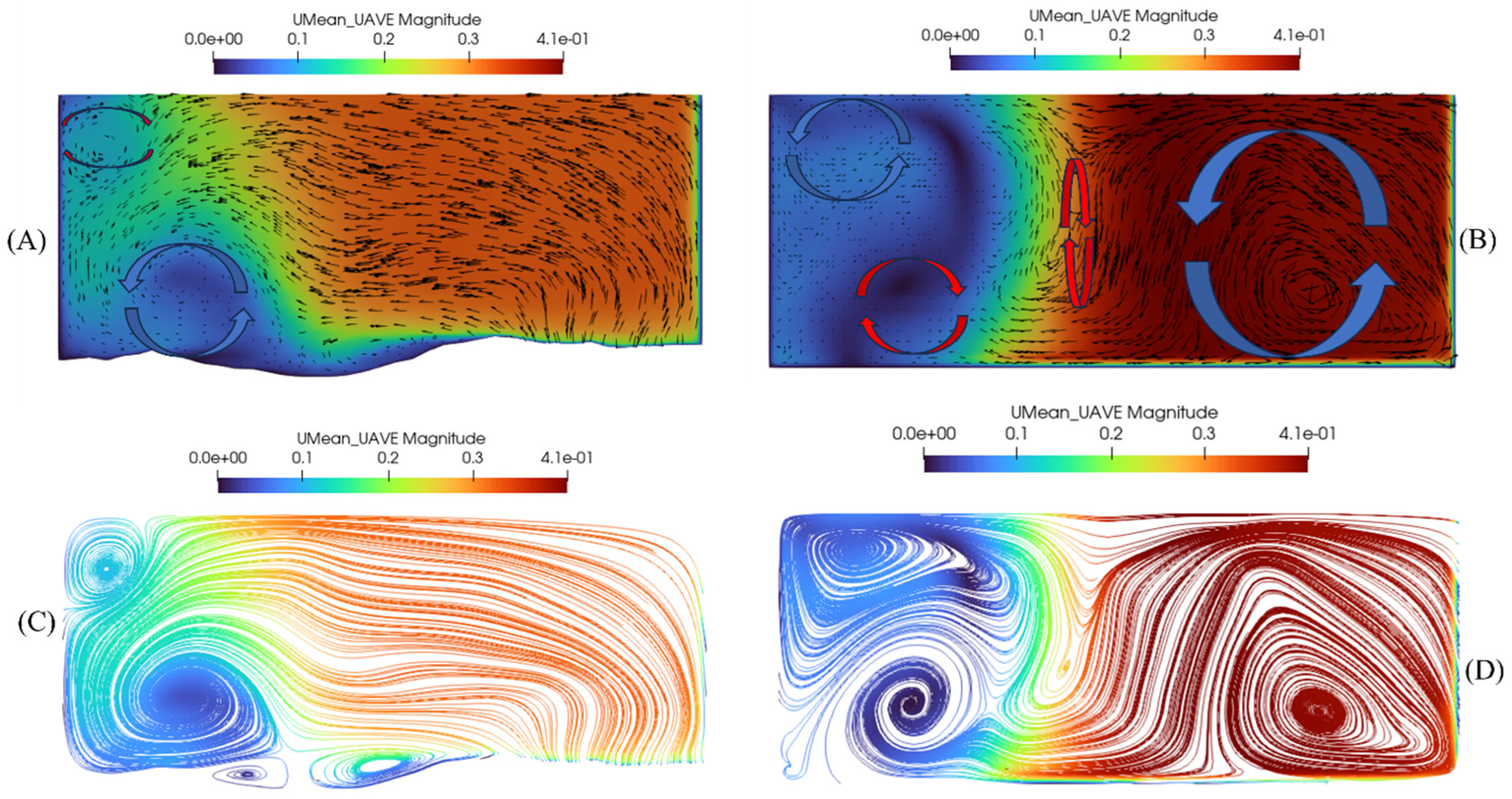
To better illustrate the time-averaged velocity field, Figure 16A (degraded bed), B (flatbed) display the X = 0.65 cross section of the downstream channel, with the in-plane component (v; w) depicted using vectors and the normal component (u) through color representation. Secondary circulation cells evident in the vector distributions are labelled. Additionally, flow streamlines for each case at the same section are shown in Figure 16C,D.
The separation zone in the flatbed scenario exists throughout the entire water column, but it has two vertically stacked counter-rotating recirculation cells, and its width becomes narrower near the bed. Alternatively, the separation zone in the degraded bed case is wider near the bed, and, most importantly, its transverse secondary circulation cells have different rotation than in the flatbed case. This may be related to the more significant lateral velocity vectors in the degraded bed scenario, which does not display circulation cells outside of the separation zone at X = 0.65. On the other hand, Figure 16B,D highlight that in the flatbed case, two counter-rotating cells occur in the main confluence flow outside of the separation zone. One narrow clockwise circulation cell is directly adjacent to the separation zone shear layer and is associated with the tributary flow path. The other larger cell is associated with the main channel flow. The presence of these two cells illustrates the merging of the tributary flow into the main channel flow. To examine this process further, Figure 17 provides streamlines at sections upstream and downstream for both cases. Immediately upstream (X = 0.50) in the flatbed case, the narrow central cell is larger with greater circulation before integration (Figure 17B), whereas complete mixing of the two flows has occurred further downstream (Figure 17D). These results portray the cohesive convergence of the two flow paths and provide a concise visual representation of the confluence hydrodynamics. Interestingly, the main channel cell begins to develop further downstream (X = 0.95) in the degraded bed case (Figure 17D), indicating the evolving nature of the flow patterns along the studied reach.
The bed shear, which is influenced by the secondary circulation cells, contributes to the scouring that can be seen in the cross section of the degraded bed case. In open-channel confluences, the momentum near the surface is generally greater than near the bed. This is due to the acceleration of water near the surface caused by velocity gradients resulting from the merging of tributary and main channel flows. The presence of roughness at the boundary of a fluid flow significantly influences the velocity and momentum distribution, resulting in reduced values near the bed compared to the free surface. This variation in momentum distribution has significant implications for flow dynamics, sediment transport, and channel morphology in confluence regions. Due to the greater lateral momentum near the surface compared to near the bed, the water at the surface has a noticeable velocity towards the shear layer. The water surface is slightly deflected by the incoming water from the main channel. This generates a secondary current that is visible in the depicted diagram (Figure 16B). The cross sections also show that the secondary flow in the degraded bed scenario is notably distinct from the one in the flatbed scenario, primarily because of the existence of the depositional bar.

3.2.4. Vorticity

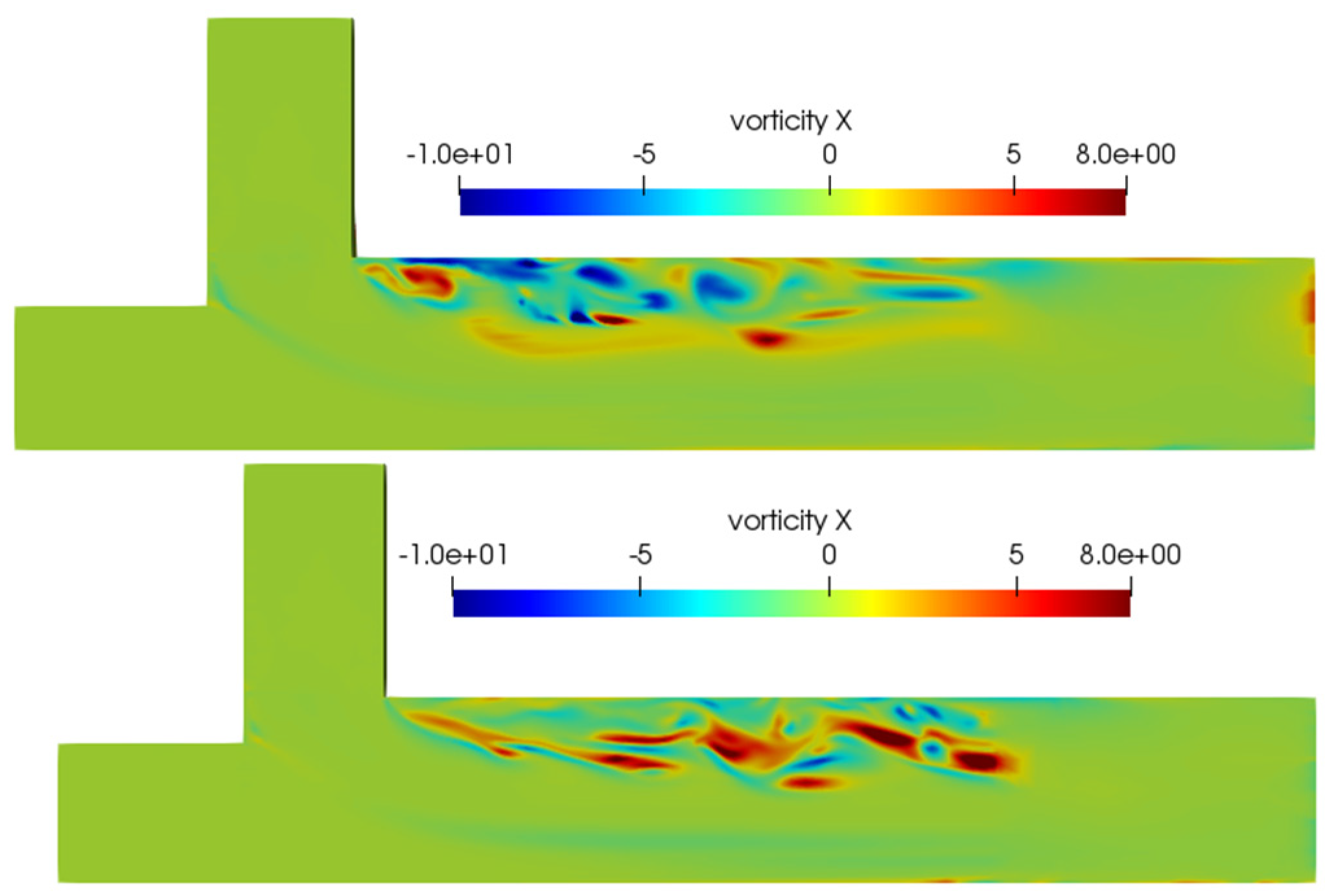
The mixing structure of the two cases displays variations, which are also evident in the patterns of vorticity, as shown in a horizontal plane near the free surface (Figure 18) and in sections (Figure 19). These variations result primarily from differences in geometry and the interactions between the separated shear layers on either side of the separation zone [53]. In both situations, a strong shear layer arises close to the inner bank. The blue (negative) vorticity near the inner bank in the degraded bed case (Figure 18 top and Figure 19A,B) is consistent with reverse secondary circulation in the recirculation zone (Figure 16A,C), which is caused by the sudden drop in flow depth in this area due to the presence of the upstream bar. The results depicted in Figure 19 demonstrate how the characteristics of the flume and flow affect the behavior of the vortical structures in the separation zone.

3.2.5. TKE

TKE was investigated in two different cross sections for both flat and degraded bed. For instances of degraded beds, significant values of TKE are noticed in the mixing layer between the converging flows (refer to cross section X = 0.3 in Figure 20A,B). Values are even higher in the shear layer around the related recirculation zone (RZ). Moving away from the RZ, the TKE values decrease, and the TKE distribution expands. This can be seen in the cross section X = 0.6 of Figure 20C,D.

4. Conclusions

A confluence channel with a degraded bed and flatbed were modeled and investigated under a number of turbulence models with two surface models using 3D OpenFOAM to compare the accuracy of six different turbulence models (RANS (standard k–ε, realizable k-ε, k-ω SST, V2F), LES, and DES). Special attention was given to the flow characteristics in the confluence zone, including secondary currents and coherent vortical structures. Data validation was performed, and the accuracy of the model was analyzed using a statistical assessment. The following highlights could be concluded from this study:
  • The simulations captured the flow patterns in the confluence zone, including the formation of recirculation zones and secondary flow, with a strong shear layer forming near the inner bank after the junction. The maximum velocity diverts from the tributary channel to the outer bank of the main channel, with substantial flow curvature through the confluence zone.
  • Velocity Prediction: The simulations showed a reasonable level of agreement with the experimental data, particularly for the VoF approach. However, there were areas closest to the bed where improvement is needed. The LES model provided the lowest average velocity error compared to other turbulence models, indicating its reliability in predicting flow velocities in complex flow geometries such as confluent channels. The k-ω SST model was found to be less suitable for simulating cases with complex geometry. In terms of accuracy in both the VoF and rigid-lid approaches, LES best predicted the confluence flow behavior, followed by realizable DES, k-ε, V2F, k-ε, and k-ω SST. Although it had higher cost of CPU time, a good agreement was observed between the LES–VoF results and the experimental data. On the other hand, RANS family models demonstrated relatively identical poor results with minor differences in the cross section immediately after the junction.
  • The VoF method was concluded to be a more promising water surface model for complex structures with compound flow behavior than the rigid-lid method.
  • The degraded bed scenario exhibited smaller recirculation zones and different secondary flow characteristics compared to the flatbed scenario. The presence of a depositional bar in the degraded bed case affected the flow patterns and secondary circulation.
  • In the degraded bed scenario, the recirculation area was discovered to be considerably shorter and narrower or not present at all near the bed as a result of the intricate interplay between the flow and the scour hole and the depositional bar. Secondary circulation in the recirculation zone had different rotation in the degraded bed case than the flatbed case due to the presence of the depositional bar.
  • The contraction of the flow in the main channel is weaker in the case of a degraded bed.
  • The simulations revealed the formation of vorticity in the confluence zone. The number and behavior of vortices were influenced by the geometry and size of the flow channels. The interactions between separated shear layers played a significant role in the formation and behavior of vortices.
  • The generation of vortices in the flow field was mainly ascribed to: (1) variation of the shear layer caused by velocity difference between two channels; and (2) fluid element swirl in the transition zone rooted in the angle between channels.
  • The obtained results show the promising applicability of OpenFOAM CFD simulations in resolving the problems associated with the confluence channel design.
  • The use of Direct Numerical Simulation (DNS) can improve the accuracy of the study, providing valuable insights into junction areas. However, it is crucial to acknowledge the computational cost associated with DNS, necessitating high-performance computing resources. Future research efforts could focus on optimizing DNS through advancements in computational power or parallelization techniques to make it more feasible for broader applications. Furthermore, to expand our understanding, we propose directing future research towards investigating outfall mixing in the confluence area. This unexplored aspect holds the potential to uncover new dynamics and consequences, contributing to the overall advancement of the field. In balancing the benefits and challenges of DNS, coupled with exploring novel research directions, we aim to provide a more comprehensive overview of our work and stimulate further advancements in the field.

Author Contributions

All authors contributed to the study conception and design. Material preparation, data collection, and analysis were performed by E.B., A.M. and C.D.R. The first draft of the manuscript was written by E.B., and all authors commented on previous versions of the manuscript. All authors have read and agreed to the published version of the manuscript.

Funding

The research was funded by the Natural Sciences and Engineering Research Council of Canada (NSERC).

Data Availability Statement

Part of the data is available upon request from the corresponding author.

Conflicts of Interest

The authors declare no conflict of interest.

Nomenclature

SymbolDefinition
RANSReynolds-Averaged Navier–Stokes
LESLarge-eddy simulation
DESDetached eddy simulation
VoFVolume of fluid
NRMSENormalized root-mean-square error
DNSDirect Numerical Simulation
RNGRenormalization group-based
FVMFinite volume method
LiDARLight detection and ranging
PISOPressure implicit with splitting of operator
SIMPLESemi-implicit method for pressure-linked equations
CFDComputational fluid dynamic
NSNavier–Stokes
WMLESWall model LES
RMSERoot-mean-square error
SGSSub Grid-Scale
αConfluence junction angle
RQDischarge ratio
QtTributary discharge
QmMain channel upstream discharge
QdMain channel downstream discharge (Total discharge)
DWater depth
ReReynolds number
FrFroude number
U r Velocity parallel to the wall
U τ Shear velocity
τ Bed shear stress
ERoughness parameter
Υ + Nondimensional wall distance
Υ Normal distance to the wall
μ Fluid kinematic viscosity
κ von Karman constant
ρDensity of the fluid
PPressure
uiMean velocity in the i-direction
u i Fluctuating components
tTime
υKinematic viscosity
u i u j ¯ Time-averaged turbulent Reynolds shear stresses
gGravitational acceleration
u i u j Turbulent effects
Cut-off width in LES models
u ~ i Favre-averaged velocity in tensor notation
ρ Fluid density
ϑ t Eddy viscosity
S i j Local mean strain rate
CsSmagorinsky constant
d wall Normal distance to the nearest wall
hMesh interval
dx, dy, dzLocal mesh dimensions
YAbsolute distance from the wall
UVelocity streamwise component
ZElevation above the bottom of the flume

References

  1. Yuan, S.; Xu, L.; Tang, H.; Xiao, Y.; Gualtieri, C. The dynamics of river confluences and their effects on the ecology of aquatic environment: A review. J. Hydrodyn. 2022, 34, 1–14. [Google Scholar] [CrossRef]
  2. Mosley, M.P. An experimental study of channel confluences. J. Geol. 1976, 84, 535–562. [Google Scholar] [CrossRef]
  3. Sukhodolov, A.N.; Krick, J.; Sukhodolova, T.A.; Cheng, Z.; Rhoads, B.L.; Constantinescu, G.S. Turbulent flow structure at a discordant river confluence: Asymmetric jet dynamics with implications for channel morphology. J. Geophys. Res. Earth Surf. 2017, 122, 1278–1293. [Google Scholar] [CrossRef]
  4. Sukhodolov, A.N.; Sukhodolova, T.A. Dynamics of flow at concordant gravel bed river confluences: Effects of junction angle and momentum flux ratio. J. Geophys. Res. Earth Surf. 2019, 124, 588–615. [Google Scholar] [CrossRef]
  5. Bilal, A.; Xie, Q.; Zhai, Y. Flow, Sediment, and Morpho-Dynamics of River Confluence in Tidal and Non-Tidal Environments. J. Mar. Sci. Eng. 2020, 8, 591. [Google Scholar] [CrossRef]
  6. Cheng, Z.; Constantinescu, G. Stratification effects on hydrodynamics and mixing at a river confluence with discordant bed. Environ. Fluid Mech. 2020, 20, 843–872. [Google Scholar] [CrossRef]
  7. Zhang, Z.; Lin, Y. An Experimental Study on the Influence of Drastically Varying Discharge Ratios on Bed Topography and Flow Structure at Urban Channel Confluences. Water 2021, 13, 1147. [Google Scholar] [CrossRef]
  8. Balouchi, B.; Shafai-Bejestan, M.; Ruther, N.; Rahmanshahi, M. Experimental investigation of flow pattern over a fully developed bed at a 60° river confluence in large floods. Acta Geophys. 2022, 70, 2283–2296. [Google Scholar] [CrossRef]
  9. Wang, J.; Hassan, M.A.; Saletti, M.; Yang, X.; Zhou, H.; Zhou, J. Experimental study on the mitigation effects of deflection walls on debris flow hazards at the confluence of tributary and main river. Bull. Eng. Geol. Environ. 2022, 81, 354. [Google Scholar] [CrossRef]
  10. Yuan, S.; Tang, H.; Xiao, Y.; Xia, Y.; Melching, C.; Li, Z. Phosphorus contamination of the surface sediment at a river confluence. J. Hydrol. 2019, 573, 568–580. [Google Scholar] [CrossRef]
  11. Lewis, Q.; Rhoads, B.; Sukhodolov, A.; Constantinescu, G. Advective lateral transport of streamwise momentum governs mixing at Small River confluences. Water Resour. Res. 2020, 56, e2019WR026817. [Google Scholar] [CrossRef]
  12. Yuan, S.; Tang, H.; Li, K.; Xu, L.; Xiao, Y.; Gualtieri, C.; Rennie, C.; Melville, B. Hydrodynamics, sediment transport and morphological features at the confluence between the Yangtze River and the Poyang Lake. Water Resour. Res. 2021, 57, e2020WR028284. [Google Scholar] [CrossRef]
  13. Horna-Munoz, D.; Constantinescu, G.; Rhoads, B.; Lewis, Q.; Sukhodolov, A. Density effects at a concordant bed natural river confluence. Water Resour. Res. 2020, 56, e2019WR026217. [Google Scholar] [CrossRef]
  14. Bradbrook, K.F.; Lane, S.N.; Richards, K.S. Numerical simulation of three-dimensional, time-averaged flow structure at river channel confluences. Water Resour. Res. 2000, 36, 2731–2746. [Google Scholar] [CrossRef]
  15. Jiang, C.; Constantinescu, G.; Yuan, S.; Tang, H. Flow hydrodynamics, density contrast effects and mixing at the confluence between the Yangtze River and the Poyang Lake channel. Environ. Fluid Mech. 2022, 23, 229–257. [Google Scholar] [CrossRef]
  16. Sagaut, P.; Deck, S.; Terracol, M. Multiscale and Multiresolution Approaches in Turbulence-LES, DES and Hybrid RANS/LES Methods: Applications and Guidelines; Imperial Press: London, UK, 2013. [Google Scholar]
  17. Huang, J.; Weber, L.J.; Lai, Y.G. Three-dimensional numerical study of flows in open-channel junctions. J. Hydraul. Eng. 2002, 128, 268–280. [Google Scholar] [CrossRef]
  18. Shumate, E.D. Experimental Description of Flow at an Open-Channel Junction. Doctoral Dissertation, University of Iowa, Iowa City, IA, USA, 1998. [Google Scholar]
  19. Shakibainia, A.; Tabatabai, M.R.M.; Zarrati, A.R. Three-dimensional numerical study of flow structure in channel confluences. Can. J. Civ. Eng. 2010, 37, 772–781. [Google Scholar] [CrossRef]
  20. Song, C.G.; Seo, I.W.; Kim, Y.D. Analysis of secondary current effect in the modeling of shallow flow in open channels. Adv. Water Resour. 2012, 41, 29–48. [Google Scholar] [CrossRef]
  21. Shaheed, R.; Mohammadian, A.; Kheirkhah Gildeh, H. A comparison of standard k–ε and realizable k–ε turbulence models in curved and confluent channels. Environ. Fluid Mech. 2019, 19, 543–568. [Google Scholar] [CrossRef]
  22. Tang, H.; Zhang, H.; Yuan, S. Hydrodynamics and contaminant transport on a degraded bed at a 90-degree channel confluence. Environ. Fluid Mech. 2018, 18, 443–463. [Google Scholar] [CrossRef]
  23. Penna, N.; De Marchis, M.; Canelas, O.B.; Napoli, E.; Cardoso, A.H.; Gaudio, R. Effect of the junction angle on turbulent flow at a hydraulic confluence. Water 2018, 10, 469. [Google Scholar] [CrossRef]
  24. Schindfessel, L.; Creëlle, S.; De Mulder, T. How different cross-sectional shapes influence the separation zone of an open-channel confluence. J. Hydraul. Eng. 2017, 143, 04017036. [Google Scholar] [CrossRef]
  25. Le, T.B.; Khosronejad, A.; Sotiropoulos, F.; Bartelt, N.; Woldeamlak, S.; Dewall, P. Large-eddy simulation of the Mississippi River under base-flow condition: Hydrodynamics of a natural diffluence-confluence region. J. Hydraul. Res. 2019, 57, 836–851. [Google Scholar] [CrossRef]
  26. Ramos, P.X.; Schindfessel, L.; Pêgo, J.P.; Mulder, T.D. Large-Eddy Simulations of T-shaped open-channel confluences with different downstream channel widths. In Proceedings of the 7th International Junior Researcher and Engineer Workshop on Hydraulic Structures, Denver, CO, USA, 25–27 June 2019. [Google Scholar]
  27. Yuan, S.; Tang, H.; Xiao, Y.; Qiu, X.; Zhang, H.; Yu, D. Turbulent flow structure at a 90-degree open channel confluence: Accounting for the distortion of the shear layer. J. Hydro-Environ. Res. 2016, 12, 130–147. [Google Scholar] [CrossRef]
  28. Herrera-Granados, O. Numerical analysis of flow behavior in a rectangular channel with submerged weirs. Water 2021, 13, 1396. [Google Scholar] [CrossRef]
  29. Duguay, J.; Biron, P.; Buffin-Bélanger, T. Large-scale turbulent mixing at a mesoscale confluence assessed through drone imagery and eddy-resolved modelling. Earth Surf. Process. Landf. 2022, 47, 345–363. [Google Scholar] [CrossRef]
  30. Constantinescu, G.; Miyawaki, S.; Rhoads, B.; Sukhodolov, A.; Kirkil, G. Structure of turbulent flow at a river confluence with momentum and velocity ratios close to 1: Insight provided by an eddy-resolving numerical simulation. Water Resour. Res. 2011, 47, W05507. [Google Scholar] [CrossRef]
  31. Ramos, P.X.; Schindfessel, L.; Pêgo, J.P.; De Mulder, T. Flat vs. curved rigid-lid LES computations of an open-channel confluence. J. Hydroinform. 2019, 21, 318–334. [Google Scholar] [CrossRef]
  32. Yan, X.-F.; Duan, H.-F.; Yang, Q.-Y.; Liu, T.-H.; Sun, Y.; Wang, X.-K. Numerical assessments of bed morphological evolution in mountain river confluences under effects of hydro-morphological factors. Hydrol. Process. 2022, 36, e14488. [Google Scholar] [CrossRef]
  33. Yu, Q.; Yuan, S.; Rennie, C.D. Experiments on the morphodynamics of open channel confluences: Implications for the accumulation of contaminated sediments. J. Geophys. Res. Earth Surf. 2020, 125, e2019JF005438. [Google Scholar] [CrossRef]
  34. Karches, T. Towards a Dynamic Compartmental Model of a Lamellar Settler. Symmetry 2023, 15, 864. [Google Scholar] [CrossRef]
  35. Launder, B.E.; Spalding, D.B. The numerical computation of turbulent flows. In Numerical Prediction of Flow, Heat Transfer, Turbulence and Combustion; Elsevier: Amsterdam, The Netherlands, 1983; pp. 96–116. [Google Scholar]
  36. Bradbrook, K.F.; Biron, P.M.; Lane, S.N.; Richards, K.S.; Roy, A.G. Investigation of controls on secondary circulation in a simple confluence geometry using a three-dimensional numerical model. Hydrol. Process. 1998, 12, 1371–1396. [Google Scholar] [CrossRef]
  37. Shaheed, R.; Yan, X.; Mohammadian, A. Review and comparison of numerical simulations of secondary flow in river confluences. Water 2021, 13, 1917. [Google Scholar] [CrossRef]
  38. Rhoads, B.L. Mean structure of transport-effective flows at an asymmetrical confluence when the main stream is dominant. In Coherent Flow Structures in Open Channels; Wiley: Chichester, UK, 1996; pp. 491–517. [Google Scholar]
  39. Weerakoon, S.B. Three-dimensional calculation of flow in river onfluences using boundary fitted coordinates. J. Hydrosci. Hydraul. Eng. 1989, 7, 51–62. [Google Scholar]
  40. Günther, T. Visibility, topology, and inertia: New methods in flow visualization. IEEE Comput. Graph. Appl. 2020, 40, 103–111. [Google Scholar] [CrossRef] [PubMed]
  41. Constantinescu, G.; Miyawaki, S.; Rhoads, B.; Sukhodolov, A. Numerical analysis of the effect of momentum ratio on the dynamics and sediment-entrainment capacity of coherent flow structures at a stream confluence. J. Geophys. Res. Earth Surf. 2012, 117, F04028. [Google Scholar] [CrossRef]
  42. Wilcox, D.C. Reynolds Averaging. In Turbulence Modeling for CFD, 3rd ed.; D C W Industries Inc.: La Canada Flintridge, CA, Canada, 2006; pp. 34–38. [Google Scholar]
  43. Saffman, P.G.; Wilcox, D.C. Turbulence-model predictions for turbulent boundary layers. AIAA J. 1974, 12, 541–546. [Google Scholar] [CrossRef]
  44. Schumann, U. Subgrid scale model for finite difference simulations of turbulent flows in plane channels and annuli. J. Comput. Phys. 1975, 18, 376–404. [Google Scholar] [CrossRef]
  45. Su, M.; Chen, Q.; Chiang, C.-M. Comparison of different subgrid-scale models of large eddy simulation for indoor airflow modeling. J. Fluids Eng. 2001, 123, 628–639. [Google Scholar] [CrossRef]
  46. Schindfessel, L.; Creëlle, S.; De Mulder, T. Flow patterns in an open channel confluence with increasingly dominant tributary inflow. Water 2015, 7, 4724–4751. [Google Scholar] [CrossRef]
  47. Heyrani, M.; Mohammadian, A.; Nistor, I.; Dursun, O.F. Numerical Modeling of Venturi Flume. Hydrology 2021, 8, 27. [Google Scholar] [CrossRef]
  48. Li, X.; Zhao, J. Dam-break of mixtures consisting of non-Newtonian liquids and granular particles. Powder Technol. 2018, 338, 493–505. [Google Scholar] [CrossRef]
  49. Morden, J.A.; Hemida, H.; Baker, C.J. Comparison of RANS and Detached Eddy Simulation Results to Wind-Tunnel Data for the Surface Pressures Upon a Class 43 High-Speed Train. J. Fluids Eng. 2015, 137, 041108. [Google Scholar] [CrossRef]
  50. Constantinescu, G.; Chapelet, M.; Squires, K. Turbulence modeling applied to flow over a sphere. AIAA J. 2003, 41, 1733–1742. [Google Scholar] [CrossRef]
  51. Pope, S.B. Ten questions concerning the large-eddy simulation of turbulent flows. New J. Phys. 2004, 6, 35. [Google Scholar] [CrossRef]
  52. Dinh Thanh, M.; Kimura, I.; Shimizu, Y.; Hosoda, T. Depth-averaged 2D models with effects of secondary currents for computation of flow at a channel confluence. In River Flow 2010; Bundesanstalt für Wasserbau: Karlsruhe, Germany, 2010; pp. 137–144. [Google Scholar]
  53. Constantinescu, G.; Miyawaki, S.; Rhoads, B.; Sukhodolov, A. Numerical evaluation of the effects of planform geometry and inflow conditions on flow, turbulence structure, and bed shear velocity at a stream confluence with a concordant bed. J. Geophys. Res. Earth Surf. 2014, 119, 2079–2097. [Google Scholar] [CrossRef]
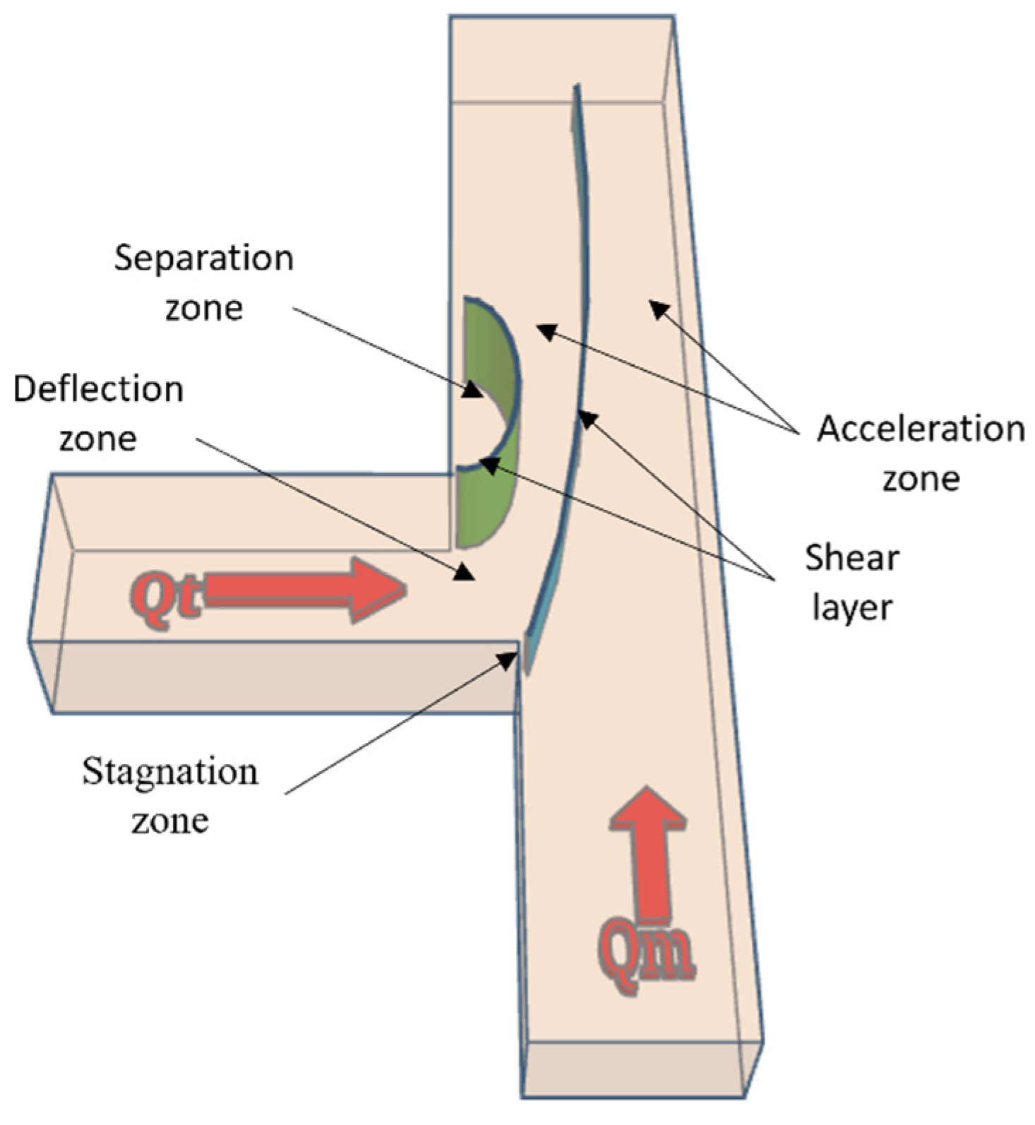
Figure 1. A schematic of the junction presenting different flow zones (Qt and Qm being the discharges of the upstream tributary and main channel, respectively).
Water 16 00085 g001
Figure 2. Measured sections, validation profiles for the simulation area, and boundary conditions of the Flume: (A) plan view (B) side view. Qt is the discharge of tributary channel, while Qm is the discharge of the main channel. Green circles mark the profiles that are used to compare the modeled and measured data (see more details in Section 3.1).
Water 16 00085 g002
Figure 3. Mesh grids of the domain in OpenFOAM platform, on a scale of 1 to 10 (for RANS turbulence models) in order to visualize the distribution of the mesh grids.
Water 16 00085 g003
Figure 4. Contour map of equilibrium bed morphology in Salome platform. The red solid circle, red dashed circle, red solid rectangle, cyan solid circle, and cyan dashed circle indicate the mid-channel scour hole, downstream scour hole, corner scour hole, upstream bar, and downstream bar, respectively.
Water 16 00085 g004
Figure 5. Measured and modeled streamwise velocities (m/s) (Volume of Fluid) at X = −0.1 and (A) Y = 0.05, (B) Y = 0.21, (C) Y = 0.35. The height of the channel (Z) is identical for all cases.
Water 16 00085 g005
Figure 6. Measured and modeled streamwise velocities (m/s) (Volume of Fluid) at X = 0 and (A) Y = 0.05, (B) Y = 0.21, (C) Y = 0.35. The height of the channel (Z) is identical for all cases.
Water 16 00085 g006
Figure 7. Measured and modeled streamwise velocities (m/s) (Volume of Fluid) at X = 0.3 and (A) Y = 0.05, (B) Y = 0.21, (C) Y = 0. 35. The height of the channel (Z) is identical for all cases.
Water 16 00085 g007
Figure 8. Measured and modeled streamwise velocities (m/s) (Rigid lid) at X = −0.1 and (A) Y = 0.05, (B) Y = 0.21, (C) Y = 0.35. The height of the figures (Z) is identical for all cases.
Water 16 00085 g008
Figure 9. Measured and modeled streamwise velocities (m/s) (Rigid lid) at X = 0 and (A) Y = 0.05, (B) Y = 0.21, (C) Y = 0.35. The height of the figures (Z) is identical for all cases.
Water 16 00085 g009
Figure 10. Measured and modeled streamwise velocities (m/s) (Rigid lid) at X = 0.3 and (A) Y = 0.05, (B) Y = 0.21, (C) Y = 0.35. The height of the channel (Z) is identical for all cases.
Water 16 00085 g010
Figure 11. Comparison of measured and predicted TKE profiles at X = −0.1 and (A) Y = 0.05, (B) Y = 0.21, (C) Y = 0.35.
Water 16 00085 g011
Figure 12. Comparison of measured and predicted TKE (resolved) profiles at X = 0.3 and (A) Y = 0.05, (B) Y = 0.21, (C) Y = 0.35.
Water 16 00085 g012
Figure 13. Distribution of time-averaged longitudinal velocity (m/s) after reaching the steady state (top; degraded bed, bottom; flatbed).
Water 16 00085 g013
Figure 14. Distribution of time-averaged longitudinal velocity (m/s) after the steady state at X = 0.2 (Left; degraded bed, Right; flatbed).
Water 16 00085 g014
Figure 15. Streamlines of simulated time-averaged flow velocity (m/s) in confluence channel with LES model: top, degraded bed; bottom, flatbed. Light blue (upstream main channel) and green (tributary channel) streamlines merge and establish the red streamlines (high velocity) in the downstream channel of the junction. The separation zone is displayed by interwoven blue streamline (top; degraded bed, bottom; flatbed).
Water 16 00085 g015
Figure 16. Cross sections of time-averaged streamwise velocity in the downstream main channel at X = 0.65 (facing downstream), also showing (A,B) in-plane component of time-averaged velocity (v-w vectors), and (C,D) streamlines (right: flatbed case; left: degraded bed case).
Water 16 00085 g016
Figure 17. Cross sections of time-averaged streamwise velocity in the downstream main channel of the flatbed case at X = 0.50 (B) and X = 0.80 (D) and degraded bed at X = 0.50 (A) and X = 0.95 (C).
Water 16 00085 g017
Figure 18. Distribution of the vorticity, in the instantaneous flow (Z = 0.12) (top: degraded bed, bottom: flatbed).
Water 16 00085 g018
Figure 19. Distribution of the vorticity (left: degraded bed, right: flatbed) ((A,B); X = 0.2 and (C,D); X = 0.65).
Water 16 00085 g019
Figure 20. Cross section at X = 0.3 (A,B) and X = 0.6 (C,D) showing the TKE (m2/s2).
Water 16 00085 g020
Table 1. Summary of some previous numerical confluence studies, compared with the current study.
ResearchModel DimensionsGoverning EquationsModel DomainSpecific Investigation
Bradbrook et al. (2000) [14]3-DRANSFlatbedFlow structures in symmetrical and asymmetrical confluences
Huang et al. (2002) [17]3-DRANSFlatbedFlow structure with different confluence angle
Shakibaeinia et al. (2010) [19]3-DRANSFlatbedSecondary flow formation with different junction angles
Constantinescu et al. (2011) [30]3-DDESDeformed bedThe effect of momentum ratio on the formation of secondary flows
Song et al. (2012) [20]3-DRANSFlatbedThe formation of secondary flows
Sukhodolov et al. (2017) [3]3-DRANSDeformed bedThe formation of secondary flows with bed discordance
Schindfessel et al. (2017) [24]3-DLESFlatbedThe effect of cross-sectional shape on separation zone
Tang et al. (2018) [22]3-DRANSDeformed bedContaminant transport and pollutant dispersion
Shaheed et al. (2019) [21]3-DRANSFlatbedSecondary flow investigations
Ramos et al. (2019) [31]3-DLESFlatbedInvestigation of flow structure by curved rigid lid
Cheng and Constantinescu (2020) [6]3-DDESDeformed bedThe impact of stratification on confluence channels
Horna-Munoz et al. (2020) [13]3-DDESDeformed bedDensity differences between flows
Yan et al. (2022) [32]2-D Deformed bedModification of anisotropy information
This Study3-DLES, DES, RANSDeformed bedInvestigation of secondary flow with different geometry
Table 2. Summary of the hydraulic and geometric data [33].
VariableSymbol (Unit)Value
Confluence junction angleα (-)90°
Discharge ratioRQ * (-)3:2
Tributary dischargeQt (L/s)9
Main channel upstream dischargeQm (L/s)6
Main channel downstream discharge
(Total discharge)
Qd (L/s)15
Water depthD (m)0.16
Reynolds numberRe (-)0.145 × 10⁵
Froude numberFr (-)0.15
Note: * RQ = Qt/Qm.
Table 3. Numbers of mesh cells.
Turbulence ModelNumber of CellsNumber of CellsNumber of CellsNumber of CellsNumber of Cells
RANS801,2541,004,2091,205,052--
LES801,2541,004,2091,205,0526,376,5027,456,287
DES801,2541,004,2091,205,0526,376,5027,456,287
Table 4. RMSE and NRMSE of the simulated velocity data vs. experimental data with the VoF method.
X (m)Y (m)Errork-εRealizable
k-ε
k-ω
SST
LESDESV2F
 
−0.1
 
0.05
RMSE (m/s)0.0090.0090.0110.0050.0060.009
NRMSE (-)0.100.100.120.060.070.10
 
−0.1
 
0.21
RMSE (m/s)0.0100.0110.0160.0050.0050.010
NRMSE0.080.090.130.040.040.08
 
−0.1
 
0.35
RMSE (m/s)0.0100.0110.0120.0020.0050.011
NRMSE0.070.080.080.010.030.07
 
0
 
0.05
RMSE (m/s)0.0040.0060.0050.0020.0030.005
NRMSE0.030.050.040.020.020.04
 
0
 
0.21
RMSE (m/s)0.0090.0070.0070.0020.0050.007
NRMSE0.050.040.040.010.030.04
 
0
 
0.35
RMSE (m/s)0.0120.0090.0110.0030.0030.008
NRMSE0.070.050.060.020.010.04
 
0.3
 
0.05
RMSE (m/s)0.1040.0960.0940.0170.0280.103
NRMSE0.510.470.460.080.140.51
 
0.3
 
0.21
RMSE (m/s)0.0840.0810.0920.0050.0100.081
NRMSE0.280.270.310.020.030.27
 
0.3
 
0.35
RMSE0.0420.0400.0450.0080.0280.041
NRMSE0.170.160.180.030.110.17
Average
NRMSE
0.150.150.160.030.150.15
Table 5. RMSE and NRMSE of the simulated data vs. experimental data with the rigid-lid method.
XYErrork-εRealizable
k-ε
k-ω
SST
LESDESV2F
 
−0.1
 
0.05
RMSE (m/s)0.0260.0260.0270.0280.0270.027
NRMSE0.280.280.300.310.300.30
 
−0.1
 
0.21
RMSE (m/s)0.0700.0710.0730.0610.0730.070
NRMSE0.600.610.630.530.630.60
 
−0.1
 
0.35
RMSE (m/s)0.0530.0530.0510.0490.0510.053
NRMSE0.360.350.340.330.340.36
 
0
 
0.05
RMSE (m/s)0.0040.0060.0050.0020.0030.005
NRMSE0.030.050.040.020.020.04
 
0
 
0.21
RMSE (m/s)0.0090.0070.0070.0020.0050.007
NRMSE0.050.040.040.010.030.04
 
0
 
0.35
RMSE (m/s)0.0120.0090.0110.0030.0030.008
NRMSE0.070.050.060.020.010.04
 
0.3
 
0.05
RMSE (m/s)0.1040.0960.0940.0170.0280.103
NRMSE0.510.470.460.080.140.51
 
0.3
 
0.21
RMSE (m/s)0.0840.0810.0920.0050.0100.081
NRMSE0.280.270.310.020.030.27
 
0.3
 
0.35
RMSE (m/s)0.0420.0400.0450.0080.0280.041
NRMSE0.170.160.180.030.110.17
Average
NRMSE
0.260.250.260.150.180.26
Disclaimer/Publisher’s Note: The statements, opinions and data contained in all publications are solely those of the individual author(s) and contributor(s) and not of MDPI and/or the editor(s). MDPI and/or the editor(s) disclaim responsibility for any injury to people or property resulting from any ideas, methods, instructions or products referred to in the content.