Article

Analysis of the Effectiveness of Water Hammer Protection Programs for Complex Long-Distance and High-Head Water Supply Projects

1
College of Water Resources Science and Engineering, Taiyuan University of Technology, Taiyuan 030024, China
2
College of Civil Engineering, Taiyuan University of Technology, Taiyuan 030024, China
*
Author to whom correspondence should be addressed.
Water 2024, 16(11), 1582; https://doi.org/10.3390/w16111582
Submission received: 6 May 2024 / Revised: 28 May 2024 / Accepted: 29 May 2024 / Published: 31 May 2024
(This article belongs to the Section Hydraulics and Hydrodynamics)

Abstract

:
The purpose of this research is to solve the complex long-distance and high-lift water supply engineering accident water hammer protection problem. Taking the Zhaojinzhuang water supply project as an example, based on the method of characteristics (MOC), the water hammer of the pumping station under the combined action of a water hammer relief valve, hydraulic-control butterfly valve, air vessel, air valve, and other water hammer protection measures is numerically simulated and calculated, and the effectiveness of the range method is analyzed, to ensure a waterproof hammer in pump stop accidents. The results show that the main factors affecting the effect of water hammer protection under the two-stage valve-closing parameters of the hydraulic-control butterfly valve are the fast-closing angle and the slow-closing time. The arrangement of the air vessel behind the pump can effectively increase the minimum water hammer pressure in the climbing section, and with the increase of the volume of the air vessel, the pump reverse speed and the maximum positive pressure increase slightly, but the overall water hammer protection effect is better. With the increase of the moment of inertia of the motor, the maximum positive pressure and minimum negative pressure of the pipeline still do not meet the requirements of the specification, and the modification cost is relatively large. The combination of the one-stage hydraulic-control butterfly valve, the air valve, the air vessel, and the water hammer relief valve can effectively reduce the volume of the air vessel. Under the optimal method, the maximum positive pressure head is 236.61 m, and the minimum negative pressure head is −3.18 m. Compared with the original method, the maximum positive pressure head is increased by 1.18%, the minimum negative pressure head is reduced by 95.78%, the maximum reverse speed of the pump is reduced by 100%, and the maximum reverse flow of the pump is reduced by 70.27%, meeting the requirements of water hammer protection. This is a safe and economical protection method.

1. Introduction

Water hammer or hydraulic transients are common problems in water distribution systems, especially for water transmission pipes. Hydraulic transient events in water distribution systems can lead to significant damage and interruptions in the system, so the study of water hammer protection for water transmission pipelines has been an important focus of research by water conservancy practitioners [1,2]. The uneven spatial and temporal distribution of water resources in China has posed challenges in many fields, such as agricultural irrigation, industrial water use, domestic water use, and water energy development, and long-distance water supply projects are an effective way to address the uneven spatial and temporal distribution of water resources [3]. Due to the limitations of distance and terrain, the vast majority of long-distance water supply projects need to be pressurized and delivered to high-level end pools through pumping stations [4]. When a pumping outage occurs, the pumping unit speed will decrease rapidly, the pressure behind the pump will decrease rapidly, and the buckling wave will be transmitted to the end of the pipeline. As the initial internal water pressure is small, the buckling wave may cause the water pressure in the transmission pipeline at higher ground to lower to the vaporization pressure, resulting in the liquid column separation phenomenon [5,6]. The bridging water hammer induced by the liquid column bridging again will cause great harm to the pipeline, valves, and pumps. At the same time, the downstream-reflected back-uplift wave tends to generate a large positive water hammer behind the pump, which will result in excessive positive pressure in the transmission pipeline, where the centerline elevation of the pipeline is low behind the pump, thus exceeding the pipeline’s design pressure-bearing criteria [7].
The water column separation in the hydraulic transition process of the pumping station pipeline system and the subsequent shut-off and rebridging water hammer can cause great potential harm to long-distance water pipeline projects. Therefore, for pumping stations that may generate water hammer hazards, water hammer calculations for accidental pump shutdowns should be carried out at all design stages [8]. The occurrence mechanism of a shut-off bridging water hammer is different from the traditional valve-closing water hammer and pump-stopping water hammer, and its occurrence location is difficult to determine in advance. Therefore, the technical measures and equipment provided at the head end of the pipeline to prevent harm from traditional pump-stop water hammers (such as various pump-stop water hammer eliminators, various types of slow-closing check valves, and valve control technologies) have little or no effect and can even produce the opposite effect. The water hammer protection measures often used include air vessels, pressure-regulating towers, air valves, water hammer relief valves, and two-stage closing of butterfly valves after pumps, etc. [9,10,11,12]. Among these listed methods, air vessels are used more frequently and with better application results due to their economic and stability advantages [13,14]. However, the air vessel must have a larger body size to meet the protection requirements of both positive and negative water hammers, and the economic cost is higher [15]. Therefore, many experts and scholars have proposed a number of programs that consist of a combination of water hammer protection measures. Rezaei et al. [16], through the water hammer protection effect, conducted a total cost comparison of a preferred methodology; the results show that the check valve and the air chamber of the joint water hammer protection measures ensure economy and effectiveness. Zeng et al. [17] conducted research on the water transfer system of a long-distance negative head pressurized pumping station. The water hammer stopping the pump under three hydraulic control modes, namely air vessel, air valve, and air valve combined with an air valve regulator room, was calculated by simulation. The results show that the use of an air valve joint and air valve regulator room protection program can effectively reduce the negative pressure in the pipe and is also able to avoid the air valve venting too quickly, as triggered by the impact of the water hammer.
The mathematical model for hydraulic transient simulation consists of multiple partial differential equations, which are simulated by most commercial software using the method of characteristics (MOC) [18,19]. The system of partial differential equations for the flow transient, which cannot be solved directly, is transformed into a system of full differential equations of a specific form; then, the system of full differential equations is integrated to produce approximate finite difference equations, which are operated according to the finite difference equations and the boundary condition equations of the piping system. However, the finite difference equation must divide the pipeline into multiple steps, divide the time into multiple periods, and solve these one by one. The finer the segments, the greater the calculation workload. Zhou et al. [20] developed an alternative coupling method by combining the second-order Godunov-type method (GTS) and MOC in order to solve the problem, and the pressure curves simulated by the GTS-MOC method were compared with the results of the MOC and the pressure curves of the GTS-MOC method. The pressure profiles simulated by the GTS-MOC method were compared with the MOC results and laboratory experiments, and the results show that this method can reproduce the transient pressure oscillations of the pipeline better than the MOC method. Wu et al. [21] proposed a one-dimensional system and three-dimensional component co-simulation method based on MOC and computational fluid dynamics (CFD) methods. By studying the interaction between the valve hammer and the pump during the rapid valve-closing process, the relative dynamic behavior obtained by the MOC-CFD co-simulation was compared with the relative dynamic behavior obtained by the MOC calculation alone. Transient simulation showed that the MOC-CFD coupling analysis is closer to the real situation due to the consideration of the influence of fluid inertia. Gong et al. [22] proposed a feature reconstruction analysis method to accurately detect and locate areas of deterioration along the pipeline distribution by estimating the distribution of pipeline characteristics using measured pressure transient trajectories, which is the inverse process of traditional forward MOC calculations. Pipeline parameters such as impedance and wave velocity from upstream to downstream were also estimated.
However, at present, most research has only studied the effect of a single combination of waterproof hammer measures on water hammer protection, and there is no systematic analysis and comparison of the effectiveness and rationality of water hammer protection under the simultaneous action of multiple-combination waterproof hammer measures. In this study, the two-stage shut-off law of butterfly valves is firstly studied for its water hammer protection effect, and a more accurate range of linear shut-off time and angle values are obtained. Then, several representative combinations of water hammer protection measures are selected for numerical simulation calculations, and the results are analyzed for effectiveness. In their water resource effectiveness analysis, Liu et al. [23] developed the energy-value analysis method using the investment environmental quality model and analyzed the ecological effectiveness; the results showed that the LPE strategy improved the ecological effectiveness and reduced the cost. Chen et al. [24] utilized a daily water balance model to assess the water-saving potential and economic effectiveness of rainwater harvesting systems across eight major cities in China. Their findings revealed that these systems could achieve a reliability ranging from 1.6% to 22.2%, though the effectiveness was less analyzed in terms of comprehensive protection against water hammer issues in long-distance water supply projects. The objectives of this study are as follows: (i) compare the effectiveness and feasibility of several combinations of water hammer protection measures and (ii) compare the influence of different design parameters on the calculation results. When a water hammer protection method is selected, it can be applied to a similar study case. The results of this study are an important reference for the comprehensive water hammer protection of long-distance and high-lift water supply projects.
The structure of this paper is as follows: in Section 2, we introduce in detail the engineering study cases and the combinations of water hammer protection measures to be studied and compared, describe the control equations of the hydraulic transition process, the calculation methods, and the boundary conditions of each water hammer protection measure, and conclude the section with the specific effectiveness analysis methods. In Section 3, each water hammer protection effect parameter is calculated under the implementation of multiple water hammer protection measure combinations; then, the effectiveness of the calculation results is analyzed using the range method. Finally, the conclusion of this study is presented in Section 4.

2. Materials and Methods

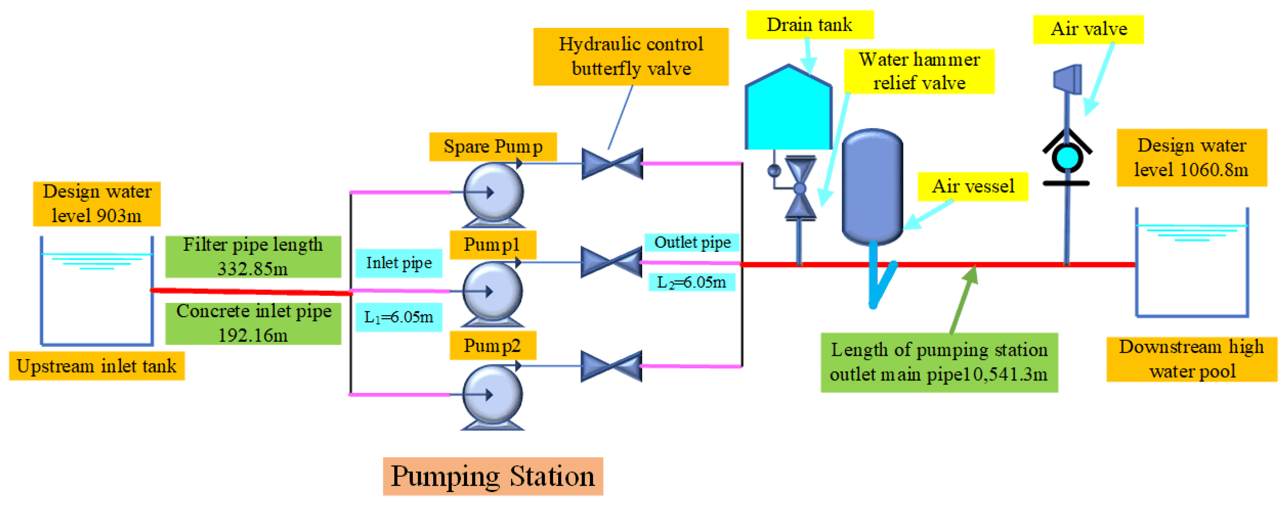
2.1. Study Area and Selection of Protective Measures

The Zhaojinzhuang Water Supply Project is located in Jinzhong City, Shanxi Province, China. The main water supply route is from the Zhaojinzhuang pumping station to the Shouyang County Economic and Technological Development Zone. The design flow rate is 0.166 m3/s, and the pipe type is DN500 K9 grade ductile iron pipe with a wall thickness of 8 mm. The total length of the main water supply pipeline is 16.8264 km (from pile number 0 + 000 to 10 + 514.3, this section of the pipeline supplies pressurized water to the pumping station; from pile number 10 + 514.3 to 16 + 826.4, this section of the pipeline delivers water for gravity flow). This numerical simulation only studies the pressurized water supply section of the pump station (from pile number 0 + 000 to 10 + 514.3). The schematic diagram of the water pipeline engineering layout is shown in Figure 1.
The Zhaojinzhuang pumping station draws water from the north side of the Xiao River. It lifts water to the high point of the pipeline through the pumping station pressure pipeline. The designed water level of the inlet tank of the pumping station is 903 m, the water level of the outlet tank is 1060.8 m, and the net head of the pumping station is 159.05 m. The pumping station is equipped with three pumps in total (two are in use, and one is a spare). The designed working flow of a single pump is 0.083 m3/s, the designed head is 186 m, and the working efficiency is 71%. The rotational inertia of the unit is 8.5 kg·m2, and the motor power is 280 kW. The pump characteristic curve is shown in Table 1.
In this paper, the method of numerical simulation using PIPENET Vision 1.8 hydraulic analysis software is used to calculate the hydraulic transition process of the water delivery system of the pumping station. Under the condition of parallel operation of two pumps, the optimal two-stage valve-closing method is screened out through the single protection of valveless protection and a hydraulic-control butterfly valve. On this basis, the two-stage hydraulic-control butterfly valve–air valve–water hammer relief valve joint protection, two-stage hydraulic-control butterfly valve–increased motor moment of inertia–air valve joint protection, two-stage hydraulic-control butterfly valve–air valve–vacuum break valve joint protection, one-stage hydraulic-control butterfly valve–air valve–air vessel joint protection, one-stage hydraulic-control butterfly valve–air valve–air vessel–air vessel–water hammer relief valve joint protection under a total of five protective measures are used to carry out the effectiveness and feasibility analysis, which provides a reference for the calculation of the hydraulic transition process and safe and economical operation of similar long-distance high-lift water supply projects.

2.2. Governing Equations and Calculation Methods

2.2.1. Basic Equations of Hydraulic Transition Process

The basic differential equation of water hammer is composed of the motion equation and the continuity equation in the water hammer process. It is a mathematical expression that fully expresses the non-constant flow law of pressurized pipe flow and is a form of the one-dimensional wave equation.
According to the elastic water column theory, it can be expressed in two equations, as follows:
(1)
The differential equation of motion is as follows:
g h x + v t + v v x + λ v 2 D v = 0
(2)
The continuous differential equation is as follows:
h t + v h x + v s i n θ + c 2 g v x = 0

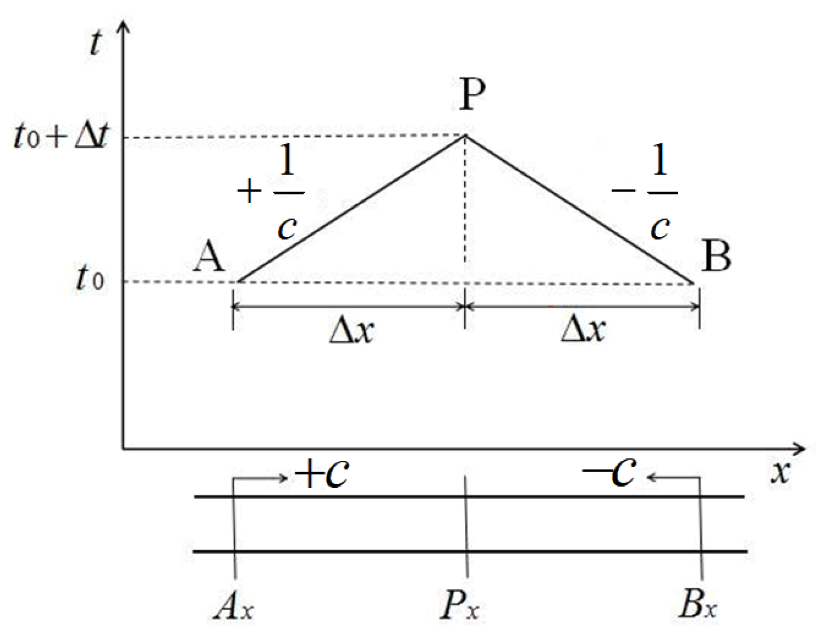
2.2.2. Characteristic Equation of Hydraulic Transition Process

On the basis of the above introduction, the quasi-linear hyperbolic partial differential equation is transformed into the form of an ordinary differential equation using MOC. Since there is a detailed introduction of MOC in the references, this paper only gives a brief introduction. Most engineering pipes are made of rigid wall materials (such as metal, concrete, rock, etc.), and the wave velocity c is much larger than the flow velocity v. At this time, the characteristic lines C+ and C will both be in a straight line. On the xt coordinate diagram, the slopes of these two lines will be +c and −c, respectively. C+ and C are used to represent the characteristic lines in both directions, that is,
d h d t + c g d v d t + c λ v v 2 g D = 0 d x / d t = + c
d h d t c g d v d t c λ v v 2 g D = 0 d x / d t = c
The corresponding finite difference equation can be simplified to the following formula:
H P H A + c g A ( Q P Q A ) + λ Δ x 2 g D A 2 Q A Q A = 0
H P H B c g A ( Q P Q B ) λ Δ x 2 g D A 2 Q B Q B = 0
Since the characteristic line is a straight line with a fixed slope, the operation process using the finite difference equation can be described by the rectangular grid in the xt coordinate diagram. As shown in Figure 2, the pipeline is divided into N steps with a distance of ∆x, and the section arrangement number is represented by i. The starting end section i = 1, the end point section i = N + 1, and the calculation period should be ∆t = ∆x/c. The operation starts from the known initial state of t = 0 (that is, the constant flow state before the transient state occurs) until the parameters of all nodes in the rectangular grid are calculated.

2.2.3. Boundary Conditions of Hydraulic-Control Butterfly Valve

The butterfly valve is a widely used valve for flow regulation and control. The butterfly valve consists of three main parts: valve body, valve flap, and shaft [25]. The installation of butterfly valves is an effective means of protection against positive pressure. The equipment is generally installed at the outlet of the pump. When water hammer occurs, the pressure in the pipeline and the reversal speed are improved by controlling the two-stage closing of the butterfly valve. The two-stage closing rule of the butterfly valve is to linearly close the valve θ1 angle within T1 and then linearly close the remaining angle θ2 within T2 to complete the two-stage valve-closing action. The head loss and flow coefficient of the hydraulic-control butterfly valve are as follows:
Δ H = C v Q 2 v v
C v = ξ / 2 g A v 2

2.2.4. Boundary Conditions of Air Valve and Vacuum Break Valve

The air valve is an essential mechanical component in the pressurized pipeline; it plays an important role in preventing pump cavitation, air release during pipeline pressurization, and air intake in the case of pipeline drainage [26]. The air intake and exhaust effect of the air valve is mainly affected by the valve caliber and intake and exhaust flow coefficients.
When air flows in at subsonic speed (0.528P0 < P < P0):
m ˙ = C i n A P 0 2 k k 1 1 R T 0 P P 0 2 k 1 P P 0 k 1 k
When air flows in at a critical velocity (P ≤ 0.528P0):
m ˙ = C i n A 2 k + 1 k + 1 2 k 1 P 0 k R T 0
When air flows out at subsonic speed (P0 < P < 1.894P0):
m ˙ = C o u t A P 2 k k 1 1 R T P 0 P 2 k 1 P 0 P k 1 k
When air flows out at a critical velocity (P ≥ 1.894P0):
m ˙ = C o u t A 2 k + 1 k + 1 2 k 1 P k R T
In numerical simulation, the control of the boundary conditions of the air valve is achieved by changing the valve caliber and flow coefficient; thus, the reasonable selection of the valve caliber and inlet and exhaust flow coefficients is the key to numerical simulation.
The boundary conditions for the vacuum break valve are the same as those for the air valve inflow (Equations (7) and (8)). In the numerical simulation process, it is also necessary to determine the valve diameter and flow coefficient. Both the vacuum break valve and the air valve are negative pressure protection devices, but they still have some different characteristics. First, the inlet pressures of these two valves are different; the air valve inlet pressure is 0 m, while the vacuum break valve inlet pressure can be set according to the actual engineering needs. Secondly, due to the small diameter of each valve and the amount of air passing through each valve, more air valves are needed to meet the demand for water hammer protection. Therefore, air valves are commonly used as auxiliary water hammer protection devices for long-distance pipelines. On the contrary, vacuum break valves can be much larger in size, so there is no need to install many vacuum break valves in the pipeline [27].

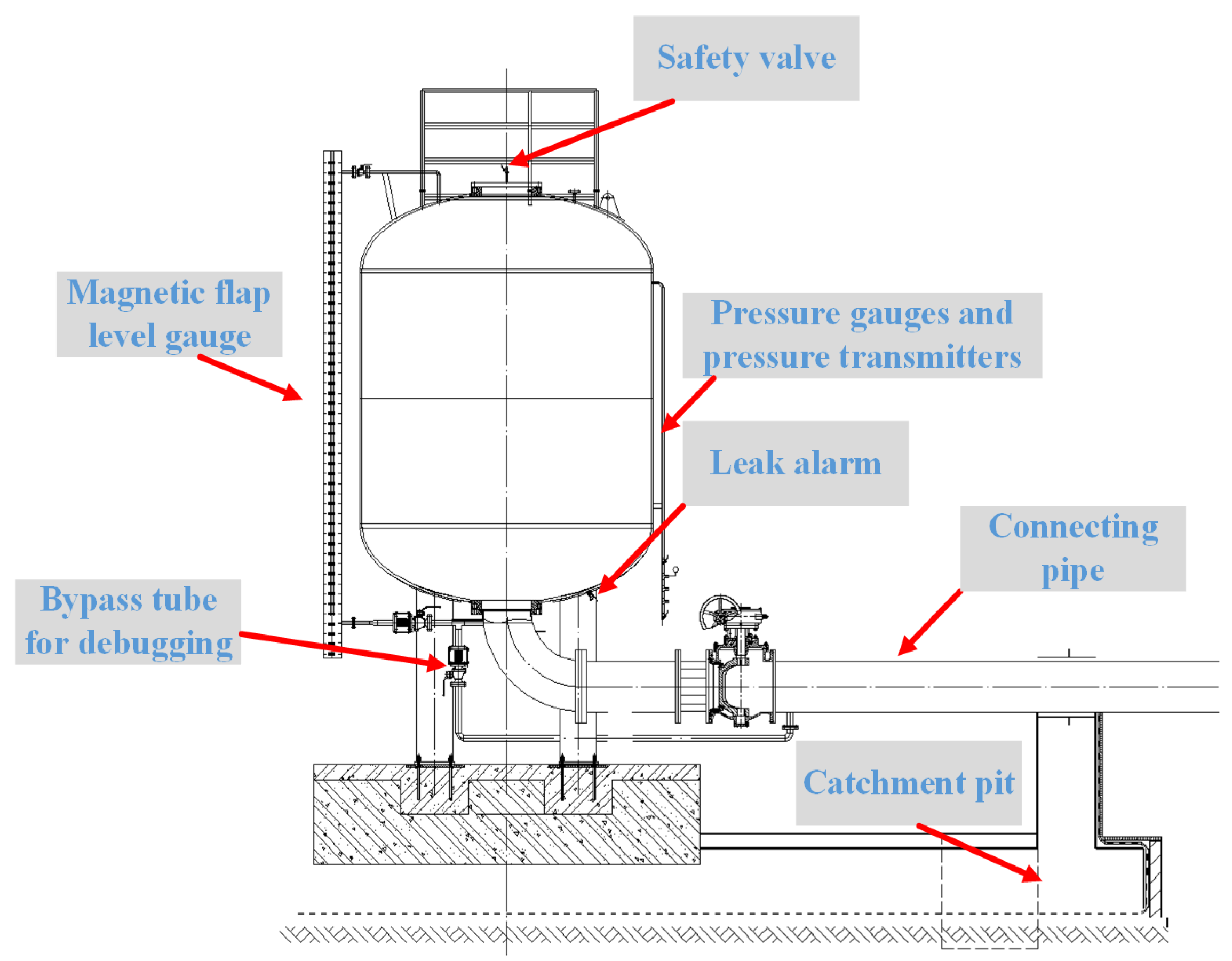
2.2.5. Boundary Conditions of Air Vessel

Air vessels are connected to the main pipeline and contain pressurized air and liquid. When the pressure in the pipeline increases, the water in the pipeline flows into the tank, and the air in the tank is pressurized. Conversely, if the pressure in the pipeline drops, the air inside the tank expands, squeezing the water and discharging it into the pipeline. The air inside the air vessel repeatedly compresses and expands in response to the water hammer in the pipeline, creating a damping effect on the hydraulic pressure changes in the pipeline. This demonstrates the ability of the air vessel to prevent pressure rises and negative pressure conditions in the pipeline. The larger the selected air volume, the greater the reduction in pressure fluctuations in the pipe. However, a larger initial air volume requires a larger volume of air vessel, which leads to a larger installation footprint and higher installation costs. Therefore, rational calculation methods and high-quality structural designs are required [28]. The schematic diagram of the structure of the air vessel is shown in Figure 3.
The gas multivariable equation is as follows:
p V n = C
The flow continuity equation is as follows:
Q p 1 = Q s t + Q p 2
The head balance equation is as follows:
H p = Z s t + ( p p 0 ) γ + k 1 Q s t Q s t
The tank water level and flow equation is as follows:
A s t d Z s t d t = Q s t

2.2.6. Boundary Conditions of Water Hammer Relief Valve

The water hammer relief valve, as a type of booster water hammer protection device, is typically installed at the beginning section of the outlet pipe after the pump. This is because this section of the pipeline has a lower elevation, and under steady-flow conditions, the initial internal water pressure is relatively high. In the event of a pump shutdown accident, when the valve behind the pump closes rapidly, the reflected positive pressure wave from the downstream water reservoir generates a significant booster water hammer behind the pump, potentially exceeding the pipeline’s design pressure standard. The working principle of the water hammer relief valve is that when the internal water pressure in the pipeline exceeds the set maximum allowable value, the valve automatically opens to discharge water, rapidly reducing the positive pressure behind the valve. When the pressure in front of the valve decreases, the valve closes by itself [29]. According to the principle of continuity, the following can be obtained:
Q P 1 Q P 2 Q P 3 = 0
H P 1 = H P 2 = H P 3
When the head Hp does not reach the operating pressure head of the water hammer relief valve, the flow before the valve is zero. When the head Hp exceeds the operating pressure head of the water hammer relief valve, the valve opens to discharge flow, and the excess flow rate is as follows:
Q P 3 = C d A G 2 g ( H P H o )

2.2.7. Basic Equations of Rotational Inertia

The moment of inertia is a measure of the inertia of a rigid body when it rotates around an axis. The role of the moment of inertia in rotational dynamics is equivalent to that of mass in linear dynamics, and it can be formally understood as the inertia of an object with respect to rotational motion, which is used to establish the relationship between several quantities, such as angular momentum, angular velocity, moment, and angular acceleration. Increasing the moment of inertia is beneficial both for negative pressure control after pump power failure and for preventing excessive pump runaway speed [30]. The basic equation for the moment of inertia of a water pump unit is
J = G D 1 2 / ( 4 g )
M r = J d ω / d t

2.3. Effectiveness Analysis Methodology

In order to analyze the above processes for the suppression of the maximum positive pressure effect, to avoid the lowest negative pressure and reduce the maximum pump reversal speed, the maximum pump reversal flow rate of the degree of influence, the listed test program, and water pressure calculations can be carried out using Range analysis. The Range method, also known as the range of error, is used to represent the number of variants in a statistic. The difference between the maximum value and the minimum value is the data obtained after the maximum value is subtracted from the minimum value. The advantages and disadvantages of the method are judged by calculating the R1 value, so as to obtain the best combination. For the minimum negative pressure, the pump maximum reversing speed, and the pump maximum reversing flow, the larger the R1 value, the better the effectiveness of the method. But for the maximum positive pressure, the smaller the R1 value, the better the effectiveness of the method. The Range formula is as follows:
R 1 = m a x ( u ) m i n ( t 1 )

3. Results and Discussion

3.1. Numerical Simulation of Hydraulic Transition without Valve Protection Measures

The valveless protection condition is analyzed with two pumps running in parallel (the most unfavorable condition). This condition reflects the characteristic quantity of the pump under the condition that the outlet valve cannot be closed normally when it needs to be closed.
As can be seen from Table 2 and Figure 4, the water began to flow backwards in the first 1.2 s after the accident stopped the pump. In the 6.5 s after the accident stopped the pump, the pump began to reverse, and the maximum reverse speed was 1900 r/min, which was 1.28 times the rated speed. The maximum reverse speed of the pump unit, according to the design standard requirements, should not exceed 1.2 times the rated speed. The maximum pressure was 233.83 m, which was 1.26 times the rated pressure. The maximum pressure after the pump outlet working valve according to the design standard requirements should not exceed 1.5 times the rated pressure of the pump outlet. The minimum pressure was −75.41 m (the pressure head below −10 m in the figure only represents the severity of the negative pressure. In actual engineering, when the pressure head drops to −10 m, the water body in the pipeline has gasified). The minimum pressure according to the requirements of the design standard should be set according to the importance of the pumping station and the annual operating time, and the minimum value should not be lower than −4 m. The maximum discharge flow was 0.148 m3/s, but a large negative pressure occurred after being imposed at a position 440 m away from the starting point of the pipeline, which does not meet the requirements of the safe operation of the pipeline. Other measures should be taken to prevent the pump outlet from being protected without valves or the pipeline safety hazard caused by excessive negative pressure when the valve refuses to operate.

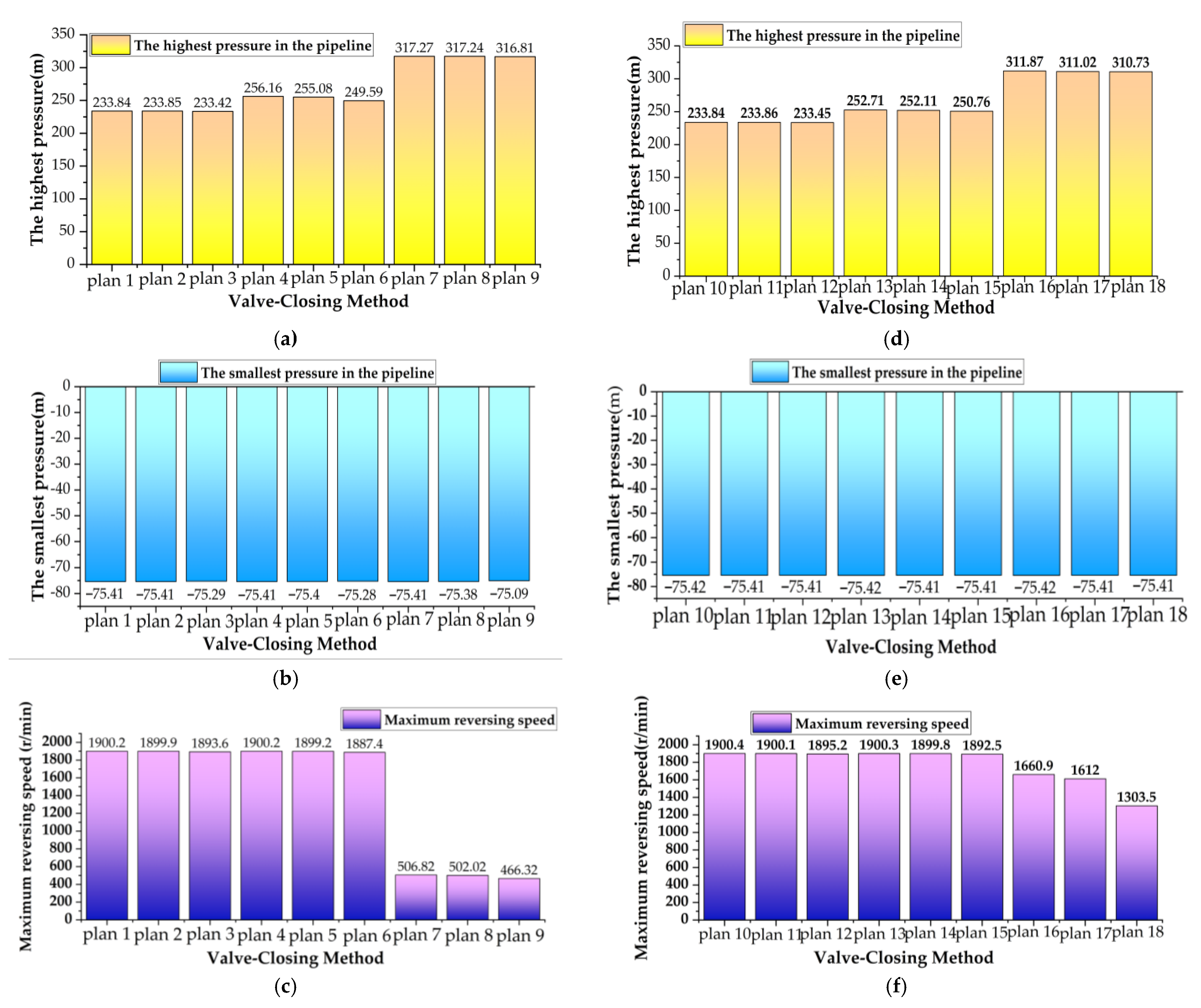
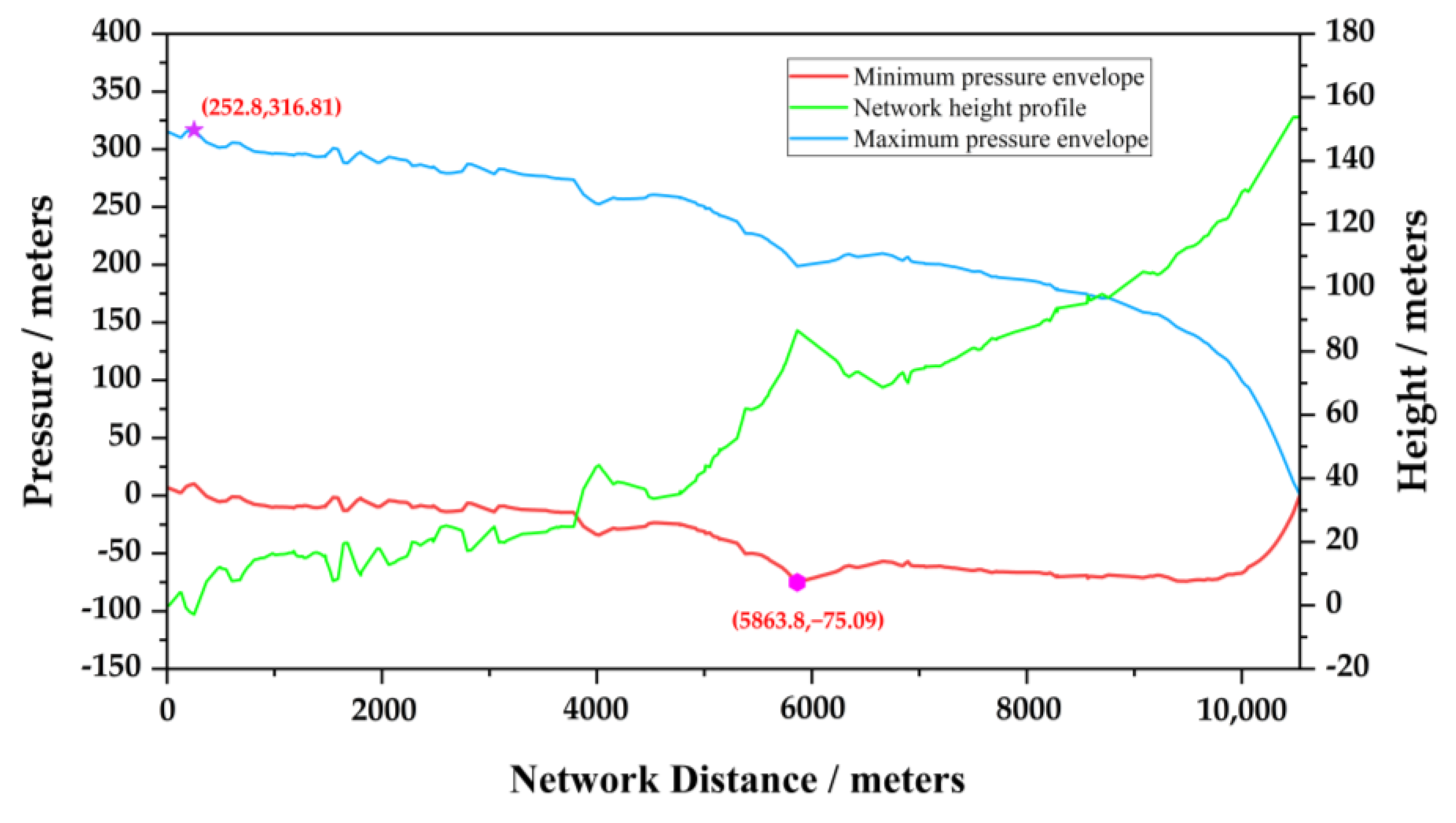
3.2. Numerical Simulation of Hydraulic Transition of Two-Stage Hydraulic-Control Butterfly Valve Protection

When selecting the valve-closing stroke, two-stage closing (fast-closing angle and fast-closing time, slow-closing angle and slow-closing time) are used to control the pressure of the pipeline and the reverse speed of the pump unit. When the two-stage hydraulic-control butterfly valve is protected, different valve-closing methods are set, as shown in Table 3. In order to facilitate the analysis of regularity, the contents of Table 3 are shown in Figure 5. The optimal valve-closing results calculated by computer simulation are shown in Table 4.
It can be seen from the calculation results in Table 3 that the two-stage hydraulic-control butterfly valve mainly affects the maximum positive pressure, the maximum inverted speed, and the maximum inverted flow in the pipeline. It can be seen from Table 4 that the addition of a hydraulic-control butterfly valve effectively curbs the inversion phenomenon of the pump unit and reduces the discharge flow of the pump, but at the same time it also greatly exacerbates the pressure increase at the pump outlet, and the minimum pressure reduction is small; thus, it needs to be further optimized on the basis of this method. This is also a common problem in the current stage of long-distance high-lift water supply projects: the maximum pressure and the minimum pressure must be determined by corresponding measures. The pressure distribution diagram under the protection of the hydraulic-control butterfly valve at the outlet of the two pumps running in parallel is shown in Figure 6.
The influence of the two-stage valve-closing law on the maximum positive pressure and the maximum reversal speed is shown in Figure 5. It can be seen from Figure 5 that the fast-closing time of each method has little effect on the maximum positive pressure and is proportional to the maximum reversal speed. The slow-closing time is inversely proportional to the maximum positive pressure and the maximum reversal speed. The fast-closing angle is inversely proportional to the maximum positive pressure and the maximum reversal speed. When the fast-closing angle is 90%, the maximum positive pressure and the maximum reversal speed are the smallest under each working condition.

3.3. Numerical Simulation of Butterfly Valve–Air Valve–Water Hammer Relief Valve Joint Protection Hydraulic Transition

According to the relevant requirements of the design standard, an air valve is generally installed every 800 to 1000 m in the pipeline. At the same time, considering the negative pressure of the pipeline, the installation of the air valve in the area with large changes in slope uplift and reduction can optimize the installation position of the pipeline air valve. Thirty-two air valves were arranged along the pipeline, with a diameter of 100 mm, an intake flow coefficient of 0.97, and an exhaust flow coefficient of 0.03. Due to the fast-in and slow-out composite air valve, this leads to higher positive pressure. A water hammer relief valve should be installed at the inlet of the main pipe, with a diameter of 1/4 to 1/5 of the main pipe diameter. The water hammer relief valve is only opened to the amount necessary to limit the pressure of the system. When selecting the diameter, it is best to take a larger diameter, so that the water hammer relief valve is only partially opened, without the need to fully open to limit the pressure of the system. On the contrary, if the diameter is too small, it is not conducive to the water hammer relief valve being able to protect the system; thus, 125 mm is used here. According to the proposed two-stage hydraulic-control butterfly valve optimal protection method, the first-stage fast-closing time is 3 s, the fast-closing angle is 90%, the second-stage slow-closing time is 10 s, and the slow-closing angle is 10%. After adding air valve protection, the maximum positive pressure of the pipeline is obtained through numerical simulation, 244.9 m, the maximum inverted flow rate of the pump is 0.069 m3/s, and the maximum inverted speed is 826.08 r/min. The maximum negative pressure of −9.46 m is significantly improved, but it is still larger than the standard requirements. The maximum negative pressure is concentrated between 8937 m and 9688 m from the starting point. The calculation results of the water hammer are shown in Figure 7. The reason why it is difficult to reduce subsequent negative pressure is because the initial water pressure in the pipeline is small, and the ability of the downstream high-water level pool to reflect the pressure wave is poor. At the same time, too many air valves are used in actual projects, which increases the difficulty of project management and the cost of equipment maintenance and repair, which is not conducive to safe operation. Therefore, it is necessary to change the engineering protection measures to further eliminate negative pressure and improve positive pressure.

3.4. Two-Stage Numerical Simulation of Joint Protection of Hydraulic-Control Butterfly Valve, Air Valve, and Increased Motor Moment of Inertia

The numerical simulation results of the hydraulic transition of the pumping station are shown in Table 5 below. It can be seen from Table 5 that as the motor moment of inertia increases, the maximum positive and negative pressure of the pipeline and the maximum reverse speed of the pump decrease, and the maximum reverse flow increases; however, the maximum positive and negative pressure still do not meet the requirements of the specification.

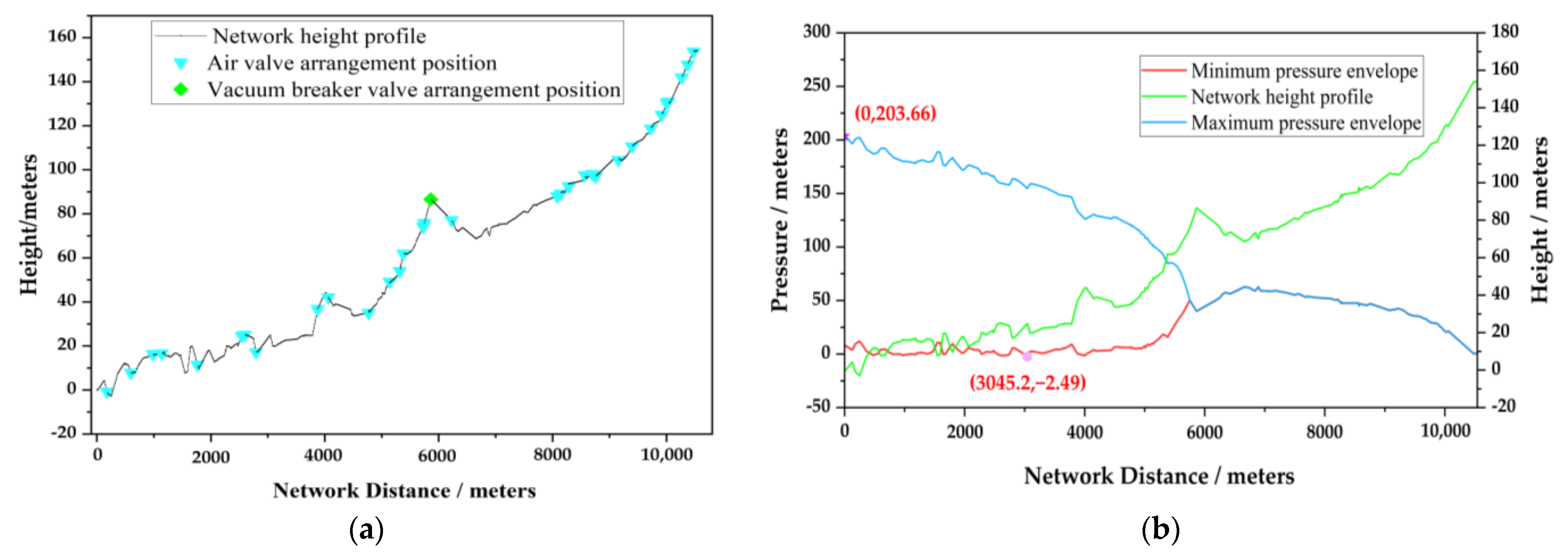
3.5. Numerical Simulation of Two-Stage Hydraulic Butterfly Valve, Air Valve, Plus Vacuum Break Valve Joint Protection

On the basis of the previous arrangement of the air valve, a vacuum break valve was installed for joint protection, and numerical simulation of the hydraulic transition of the pumping station was carried out. A vacuum break valve with a diameter of DN100 was installed 8937 m from the starting point of the pipeline. The numerical simulation results showed that the maximum positive pressure of the pipeline was 203.66 m, the rated pressure of the pipeline was 186 m, the ratio of the maximum positive pressure to the rated pressure of the pipeline was 1.09, the maximum negative pressure of the pipeline was −2.49 m, the maximum inverted speed of the pump was 1737.9 r/min, the maximum inverted flow was 0.158 m3/s, and the ratio of the maximum inverted speed to the rated speed of the pump was 1.17, which met the requirements of the specification. See Figure 8 for the corresponding pipeline layout and pressure distribution.

3.6. Numerical Simulation of One-Phase, Two-Phase, and Three-Phase Hydraulic-Control Butterfly Valve Plus Air Valve and Air Vessel Joint Protection

In practical projects, gas needs to be discharged during the normal water transportation process of the pipeline. It is not advisable to use the air vessel alone to protect against the pump-stop water hammer. Therefore, the air vessel and the hydraulic-control butterfly valve plus the air valve are used to protect against the pump stop water hammer. An air valve is installed at an interval of 800~1000 m in the pipeline, and a total of 13 air valves are laid along the project. The diameter of the air inlet hole is 100 mm, the air valve inlet flow coefficient is 0.97, and the exhaust flow coefficient is 0.03. The setting position of the air vessel is the main pipe inlet.
The pumping and power-off transition process of the pump unit is analyzed, and five kinds of air vessel protection methods are designed. Among them, the body parameters of the air vessel are shown in Table 6. The protection methods of the one-stage, two-stage, and three-stage hydraulic-control butterfly valve closing mode are formulated, compared, and analyzed. The air volume accounts for 20–25% of the total volume of the tank, and the charging pressure is 90% of the normal pressure of the pump. The combined protection calculation results of the hydraulic-control butterfly valve, air valve, and air vessel are shown in Table 7 below.
As can be seen from Table 7, an air valve is added under the 100% closure of the hydraulic-control butterfly valve in the first stage of 5 s. After the air vessel is protected, the maximum positive pressure of the pipeline is 250.58 m, the maximum inverted flow of the pump is 0.18 m3/s, the maximum inverted speed is 1364.89 r/min, and the maximum negative pressure is −0.1 m, all of which meet the design standard requirements. The calculation results of the water hammer are shown in Figure 9. This situation occurs because the depressurization wave generated by stopping the pump is transmitted to the position of the air vessel, and under the action of the high-pressure gas in the tank, the water is quickly replenished to the back of the pump. In the case of air vessel protection measures, the butterfly valve after closing the pump in two stages will have a negative impact on the water hammer protection effect of the air vessel and compromise the safe and stable operation. In order to give full play to the characteristics of the water hammer wave reflected by the air vessel and make full use of the water hammer protection characteristics, the butterfly valve after the pump should be closed quickly to the opening degree of 0.

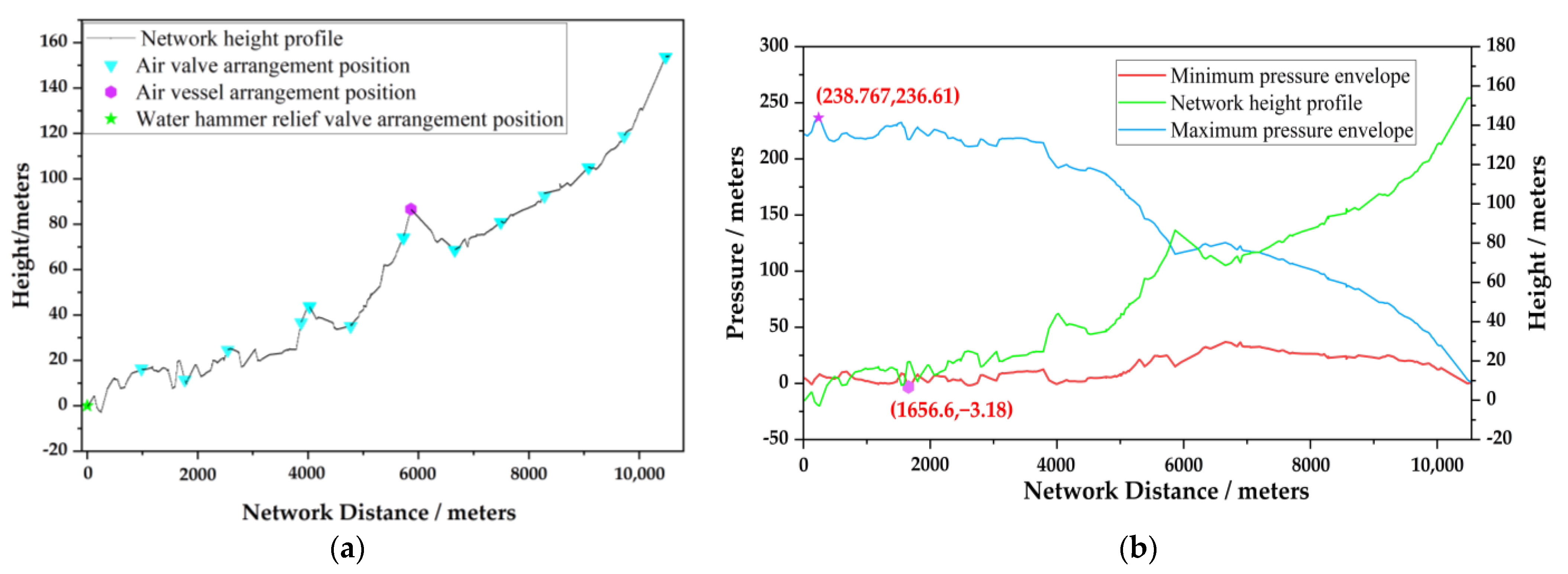
3.7. Numerical Simulation of One-Stage Joint Protection of Hydraulic-Control Butterfly Valve Plus Air Valve, Air Vessel, and Water Hammer Relief Valve

On the basis of the protection measures of the air vessel and the pump rear valve being closed quickly, in order to effectively protect against the positive and negative water hammer and optimize the shape of the air vessel, we designed a protection plan for the combined protection of the air vessel and the water hammer relief valve. The air vessel is selected as air vessel D. The water hammer relief valve is generally set in the low-terrain pipe section behind the pump with a large positive pressure. At the same time, the water hammer relief valve is arranged between the pump rear valve and the air vessel. The purpose of this setting is to use the water hammer to eliminate the negative pressure wave generated by the reflective opening of the valve of the tank and prevent the higher-terrain pipe section from having a large negative pressure. The setting parameters of the water hammer relief valve are as follows: the setting position is the inlet of the main pipe, the valve diameter and the starting pressure head are 200 mm and 200 m, respectively. Under the protective action of the water hammer elimination tank D, it is respectively set at three different positions: ① at a position of 13 m from the starting point; ② at a position of 5863.8 m from the starting point; and ③ at a position of 9820 m from the starting point. The diameter of the inlet hole is 100 mm, the intake flow coefficient of the air valve is 0.97, and the exhaust flow coefficient is 0.03. The joint protection calculation results of the one-stage hydraulic-control butterfly valve, air valve, air vessel, and water hammer relief valve are shown in Table 8. The pressure distribution diagram of the pipeline arrangement with the best protection effect by adding two pumps and the air valve, water hammer relief valve, and air vessel in parallel operation is shown in Figure 10.
It can be seen from Figure 10 that the maximum positive pressure of the high-pressure pipe section after the pump in Method 1 and Method 3 meets the pressure-bearing standard of the pipeline design (2.7 MPa). Method 2 has a better protection effect on the negative water hammer of the pipeline, and Method 2 has a more obvious effect on reducing the maximum inverted flow, and the safety margin is larger. The pump has no inversion, which also shows the superiority of this optimized layout method. The minimum negative pressure head increases first and then decreases, because the initial gas pressure is small at the beginning, which is not sufficient to quickly reduce the negative pressure in the pipe. As the initial gas pressure increases, the negative pressure elimination ability gradually becomes stronger. When the initial gas pressure is large enough, the water in the air vessel will empty, resulting in a large negative pressure in the pipeline again.
In the process of numerical simulation calculation, it is very important to set the valve diameter and starting pressure head of the water hammer relief valve reasonably. This can ensure that the negative pressure wave generated by opening the valve will not penetrate the air vessel and affect the negative pressure protection effect. The calculation results show that the maximum positive pressure, maximum reversal flow, and maximum reversal speed of the pump along the water delivery system have obvious advantages over the Section 3.6 optimal method, and the minimum negative pressure is larger but also within a reasonable range. In addition, air vessel D in method 3 is half the size of air vessel B used in the optimal method in Section 3.6, which reduces the costs of the project.

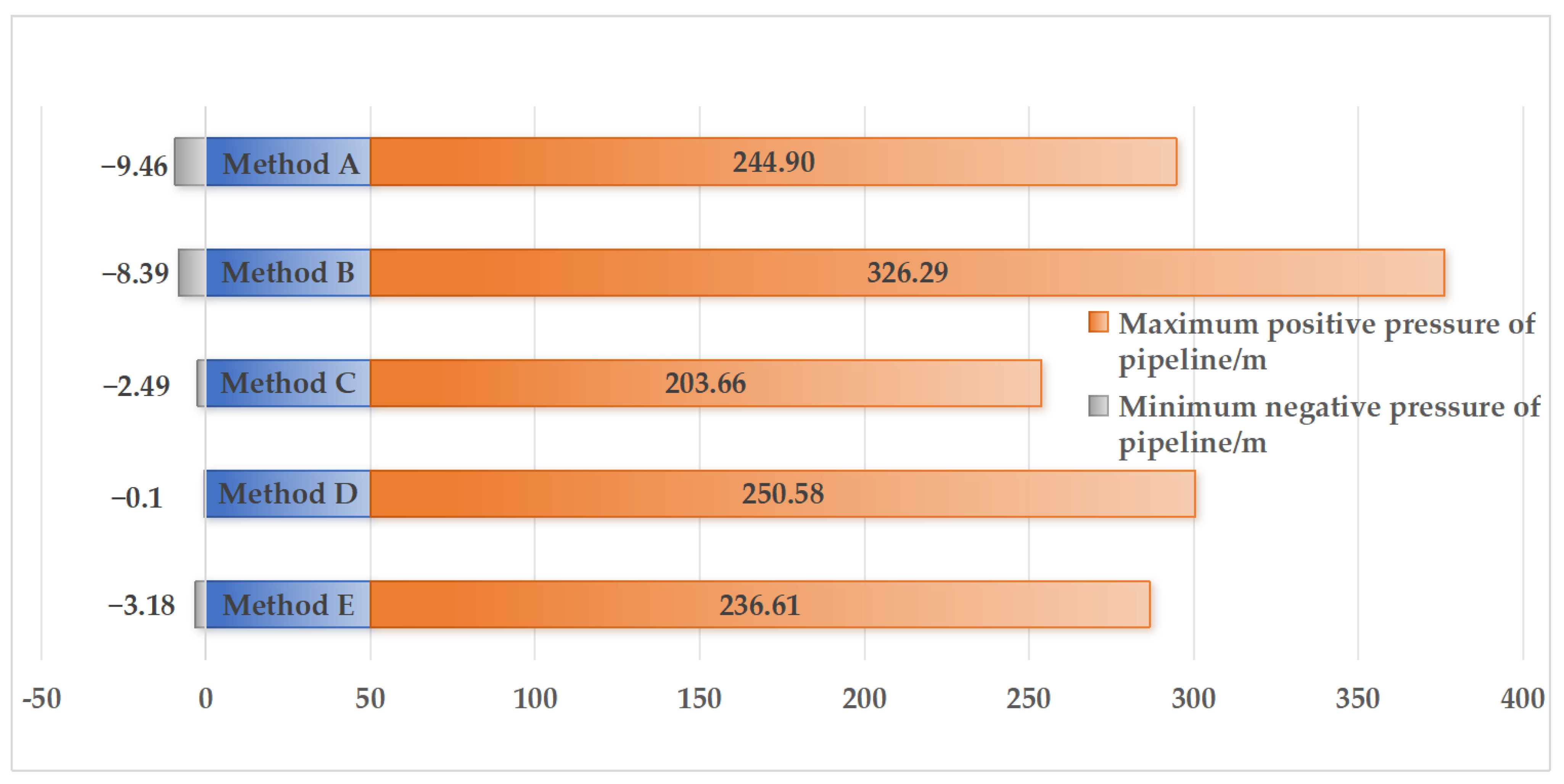
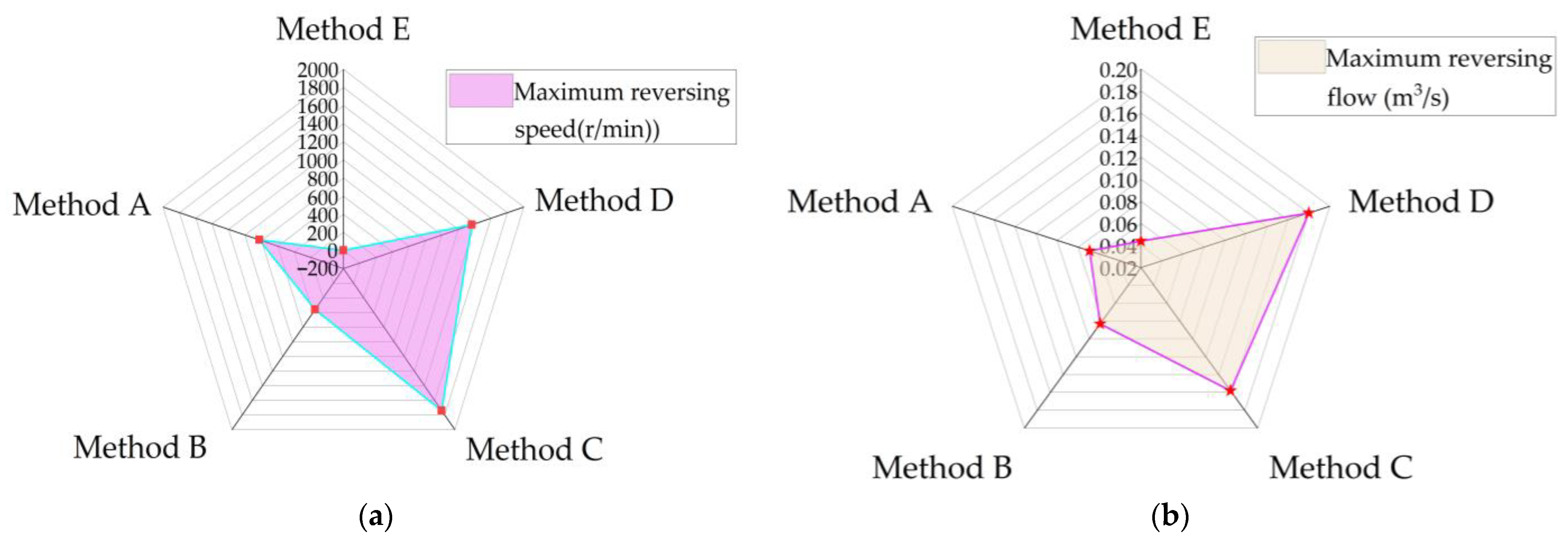
3.8. Effectiveness Analysis

Figure 11 shows the butterfly diagram of the maximum positive pressure and minimum negative pressure of the two pumps running in parallel under different water hammer protection measures, which allows comparison of the differences between the two sets of data. Five kinds of water hammer protection measures were selected, and their optimal solutions were compared. The combinations of the five water hammer protection measures were (K) valveless protection; (A) two-stage hydraulic-control butterfly valve, air valve, and water hammer relief valve; (B) two-stage hydraulic-control butterfly valve, air valve, and increased motor moment of inertia; (C) two-stage hydraulic-control butterfly valve, air valve, and vacuum break valve; (D) one-stage hydraulic-control butterfly valve, air valve, and air vessel; and (E) one-stage hydraulic-control butterfly valve plus air valve, air vessel, and water hammer relief valve.
As can be seen from Figure 11, the weakening effect of the maximum positive pressure is better in Method C and Method E, and the weakening effect of the minimum negative pressure is better in Method C, Method D, and Method E. The weakening effect of the maximum positive pressure is the best in Method C, and the weakening effect of the minimum negative pressure is the best in Method D. Therefore, the optimal solution is Method C and Method E, which are considered from the aspect of the maximum positive pressure and the minimum negative pressure alone. In Method C, the vacuum break valve has more problems and limitations in practice. When the host is shut down, the power source needs to open the vacuum break valve, and when the gas pressure is insufficient or the valve flap is stuck, the vacuum break valve cannot be opened in time, and there exists a hidden danger that the host unit will produce an impeller escape accident due to water backflow. In addition, when the main engine is turned on, the water level of the water outlet channel is raised through the operation of the main water pump. After the air in the water outlet channel is compressed to a certain pressure, the vacuum break valve is pushed open, which makes it easy to generate additional head immediately after the axial flow pump unit starts, increase the operating load of the water pump, and generate unstable factors such as strong vibration, which is not conducive to the safe and stable operation of the unit. With the adoption of Method E, the air vessel is easy to install and has low requirements for the engineering environment. The water hammer relief valve that was designed, tested, and verified is usually highly reliable, can respond quickly, and can accurately release pressure when needed to ensure the safe operation of the system. Therefore, considering the maximum positive pressure and the minimum negative pressure, the optimal solution is Method E.
Figure 12 shows the radar diagram of the maximum inverted speed and maximum inverted flow rate of the two pumps running in parallel under different water hammer protection measures. From the radar diagram (a), it can be seen that Method E is the optimal solution without inversion, and Method C has the largest inverted speed, which is 1737.9 r/min. From the radar diagram (b), it can be seen that Method E is the optimal solution, with an inverted flow rate of the pump of 0.044 m3/s; the inverted flow rate of the pump in Method D is the largest, which is 0.18 m3/s. Therefore, considering the maximum inverted speed and the maximum inverted flow rate of the pump, the optimal solution is Method E.
Table 9 shows the range analysis of each evaluation index under different water hammer protection combination measures. From the change of evaluation index k in the table, it can be seen that the range R1 is the smallest when choosing scheme C, and the effect of weakening the maximum positive pressure is the best compared with valveless protection, followed by scheme E. When choosing scheme D, the range R1 is the largest, and the effect of weakening the minimum negative pressure is the best compared with valveless protection. Schemes C and E are followed and all meet the requirements. When choosing scheme E, the range R1 is the largest, and compared with valveless protection, it has the best effect on weakening the maximum reverse speed of the pump and the maximum reverse flow of the pump. Therefore, the final optimal scheme of water hammer protection measures is the combined protection of the first-stage hydraulic-control butterfly valve plus air valve, air vessel, and water hammer relief valve. The hydraulic-control butterfly valve is closed 100% in 5 s in the first stage. The total volume of the air vessel is 7 m3, the diameter of the tank is 3 m, and the total height is 1 m. The water depth of the air vessel is 0.7 m, and the air vessel is located at 5863.8 m from the starting point. A total of 13 air valves are laid along the project. The diameter of the air inlet hole is 100 mm, the intake flow coefficient of the air valve is 0.97, and the exhaust flow coefficient is 0.03. The setting position of the water hammer discharge valve is the main pipe inlet. The valve diameter and the starting pressure head are 200 mm and 200 m, respectively.
As can be seen from Table 9, the maximum positive pressure head in the optimal scheme is 236.61 m, and the minimum negative pressure head is −3.18 m. Compared with the original scheme, the maximum positive pressure head is increased by 1.18%, the minimum negative pressure head is reduced by 95.78%, the maximum reverse speed of the pump is reduced by 100%, and the maximum reverse flow of the pump is reduced by 70.27%. In addition, the original scheme has different degrees of large negative pressure after 440 m from the starting point of the pipeline, while the negative pressure point of the optimization scheme only exists a short distance from the front end of the main pipe, which also shows that the optimization scheme not only reduces the peak value of the maximum positive pressure head and the minimum negative pressure head, but also optimizes the overall distribution of pipeline pressure; thus, the optimization scheme is ideal.

4. Conclusions

In this study, MOC is used for hydraulic transient simulation of water hammer comprehensive protection in long-distance and high-lift water supply projects, and the range method is used to analyze the effectiveness of the calculation results. The following conclusions are drawn:
  • In the example of a long-distance and high-lift water supply project, the comparison of the results of various comprehensive protection measures for water hammer shows that the combined protection scheme of one-stage hydraulic-control butterfly valve plus air valve, water hammer elimination tank, and water hammer relief valve is the most effective and economical scheme.
  • The simulation results have important reference value for the design of long-distance high-lift water supply projects with obvious characteristics, the calculation of hydraulic transition processes, and safe and economical operation. Most of the previous research work was aimed at a single water hammer protection combination, and there are few studies on the comprehensive protection measures of various water hammers and the application of water hammer elimination tanks, which do not address the reality that the pipeline distance of water hammer design is becoming longer and the head and flow are becoming larger. In this paper, the results of various water hammer comprehensive protection measures are compared, and the optimal protection measures are selected. In the design and operation of the project, the closing time, pipe diameter, and flow of each valve should be strictly controlled to ensure the safety of the project.
  • The main factors affecting the water hammer protection effect in the two-stage shut-off parameters of the hydraulic butterfly valve are the fast-shut-off angle and the slow-shut-off time.
  • There are many factors affecting the performance of waterproof hammers in long-distance water pumping stations. By comparing the calculation results of various comprehensive protection measures for water hammers and multiple sets of orthogonal experimental designs, the optimal solution can be quickly obtained, which addresses the optimization problems in previous engineering projects. By combining the protection of the water hammer elimination tank and the water hammer discharge valve, the volume of the water hammer elimination tank and the performance of the water hammer of the pipeline can be greatly optimized, which can greatly reduce the cost of the project.
In summary, in this study, we analyzed the effectiveness of the hydraulic transient simulation of water hammer comprehensive protection measures for various long-distance and high-lift water supply projects based on MOC. We only analyzed one engineering example and selected the optimal water hammer protection scheme, which proved the practicality of using the polarity method to analyze the effectiveness. In order to obtain more comprehensive results, more examples need to be analyzed.

Author Contributions

Conceptualization, Y.T., J.W. and Y.Z.; methodology, Y.T. and J.W.; software, Y.T., Q.L. and L.Y.; validation, Y.T. and L.S.; formal analysis, Y.T.; investigation, J.W.; resources, J.W., Y.Z. and Y.C.; data curation, Y.T. and L.S.; writing—original draft preparation, Y.T.; writing—review and editing, Y.T., Y.Z. and J.W.; visualization, Y.Z. and Y.C.; supervision, L.S., Y.Z. and J.W.; project administration, J.W., Y.Z. and Y.C.; funding acquisition, J.W., Y.Z. and Y.C. All authors have read and agreed to the published version of the manuscript.

Funding

This work was supported by the Free Exploration Project of Basic Research Programs of Shanxi Province, Science and Technology Department of Shanxi Province, China (20210302123169, 202203021212271), the Scientific and Technological Innovation Programs of Higher Education Institutions in Shanxi, Shanxi Provincial Education Department, China (2021L020, 2022L033), the School-level Scientific Research Programs of Taiyuan University Of Technology, Taiyuan University Of Technology, China (2022QN055), and the Graduate Education and Teaching Management Innovation Programs of Shanxi Province, Shanxi Provincial Education Department, China (2023JG031).

Data Availability Statement

The data presented in this study can be made available upon request from the authors. The data are not publicly available due to privacy restrictions.

Acknowledgments

The authors are grateful for the research collaboration.

Conflicts of Interest

The authors declare no conflicts of interest.

Nomenclature

hpressure head (m)
xpropagation distance (m)
vflow velocity (m/s)
ttime (s)
λresistance coefficient of the pipeline
Ddiameter of the pipeline (m)
θthe angle between the pipeline and the ground (°)
cpropagation speed of the water hammer wave (m/s)
gthe acceleration of gravity (m2/s)
HPhead of Point P at intersection of two lines in Figure 2 (m)
HAthe head of point A at which location x and time t are specified in Figure 2 (m)
HBthe head of point B at which location x and time t are specified in Figure 2 (m)
QPthe flow rate of point P at the intersection of two lines in Figure 2 (m3/s)
QAthe flow rate of point A at the given time of location x and time t in Figure 2 (m3/s)
QBthe flow rate of point B at the given time of location x and time t in Figure 2 (m3/s)
xthe length of a pipeline divided into N spaced steps (m)
Hhead loss (m)
Cv, Cdflow coefficient
Qrate of flow (m3/s)
ξresistance coefficient of the corresponding opening
Avopening area of the butterfly valve (m2)
m ˙ air mass flow rate (m3/s)
C i n valve inlet flow coefficient
C o u t valve outlet flow coefficient
Ainlet and exhaust valve circulation area (m2)
P0absolute pressure of the gas outside the tube (Pa)
Pabsolute pressure of the gas inside the tube (Pa)
kadiabatic index
Rgas constants
T0absolute temperature of the ambient atmosphere outside the tube (K)
Tabsolute temperature of the gas in the tube (K)
pabsolute pressure of gas in tank (Pa)
Vtank gas volume (m3)
Cgas state constant
Qp1, Qp2tank upstream and downstream flow respectively (m3/s)
Qstflow through the tank (m3/s)
Zsttank level (m)
p0atmospheric pressure outside the tank (Pa)
γunit weight of water (N/m3)
k1hydraulic loss coefficient
Asttank cross-sectional area (m2)
HPpressure at the connection between the tank and the pipeline (m)
Q P 1 Q P 2 Q P 3 flow upstream, downstream, and in front of the water hammer relief valve (m3/s)
H P 1 H P 2 H P 3 pressure head upstream, downstream and in front of the water hammer relief valve (m)
AGcross-sectional area of overflow after opening of water hammer relief valve (m2)
Hoexternal pressure head after water hammer relief valve (m)
Jrigid body moment of inertia (kg∙m2)
D1diameter of the rigid body (m)
Gtotal weight of rigid body (N)
Mrdeceleration resistance moment (N∙m)
d ω / d t angular acceleration of rotor (rad/s2)
R1range
uthe maximum or minimum values of the different parameters of method A
t1maximum or minimum value of valveless protection
Acronyms
MOCmethod of characteristics

References

  1. Ammar, H.T.; Al-Zahrani, M.A. Water Hammer Analysis for Khobar-Dammam Water Transmission Ring Line. Arab. J. Sci. Eng. 2015, 40, 2183–2199. [Google Scholar] [CrossRef]
  2. Iyanda, F.; Ayodele, I. Numerical solution for the pipe diameters and wall thickness of water hammer model using crank-nicolson algorithm. Trans. Niger. Assoc. Math. Phys. 2021, 15, 19–28. [Google Scholar]
  3. Zhang, J.; Yu, X.; An, J.; Hazrati, A. Polyline closure law design and realization in long-distance water-supply project. In Proceedings of the ASME International Mechanical Engineering Congress and Exposition, Vancouver, BC, Canada, 12–18 November 2010; pp. 129–134. [Google Scholar]
  4. Li, N.; Zhang, J.; Shi, L.; Chen, X.; Zhang, X. Water hammer protection characteristic of combined air vessel and overpressure relief valve. J. Drain. Irrig. Mach. Eng. 2020, 38, 254–260. (In Chinese) [Google Scholar]
  5. Bergant, A.; Simpson, A.R.; Tijsseling, A.S. Water hammer with column separation: A historical review. J. Fluids Struct. 2006, 22, 135–171. [Google Scholar] [CrossRef]
  6. Zhou, L.; Wang, H.; Liu, D.; Ma, J.; Wang, P.; Xia, L. A second-order finite volume method for pipe flow with water column separation. J. Hydro-Environ. Res. 2017, 17, 47–55. [Google Scholar] [CrossRef]
  7. Albahrani, H.S.M. Analysis of water hammer for al-kut water supply project using the method of characteristics. Al-Qadisiya J. Eng. Sci. 2009, 2, 33–45. [Google Scholar]
  8. Wu, L.; Wang, H.; Li, X.; Sang, Z.; Chen, Z. Ultimate bearing capacity analysis of pipelines under water hammer. J. Pipeline Syst. Eng. Pract. 2024, 15, 04023063. [Google Scholar] [CrossRef]
  9. Miao, D.; Zhang, J.; Chen, S.; Yu, X. Water hammer suppression for long distance water supply systems by combining the air vessel and valve. J. Water Supply Res. Technol.-Aqua 2017, 66, 319–326. [Google Scholar] [CrossRef]
  10. Arefi, M.H.; Ghaeini-Hessaroeyeh, M.; Memarzadeh, R. Numerical modeling of water hammer in long water transmission pipeline. Appl. Water Sci. 2021, 11, 140. [Google Scholar] [CrossRef]
  11. Wang, L.; Wang, F.; Karney, B.W.; Malekpour, A.; Wang, Z. Influence of velocity head on filling transients in a branched pipeline. Eng. Comput. 2018, 35, 2502–2513. [Google Scholar] [CrossRef]
  12. Zhang, G.; Zhang, H.T.; Wu, Z.Y.; Wu, X.; Kim, H.D.; Lin, Z. Experimental studies of cavitation evolution through a butterfly valve at different regulation conditions. Exp. Fluids 2024, 65, 4. [Google Scholar] [CrossRef]
  13. Besharat, M.; Teresa Viseu, M.; Ramos, H.M. Experimental Study of Air Vessel Behavior for Energy Storage or System Protection in Water Hammer Events. Water 2017, 9, 63. [Google Scholar] [CrossRef]
  14. Sun, Q.; Wu, Y.B.; Xu, Y.; Jang, T.U. Optimal sizing of an air vessel in a long-distance water-supply pumping system using the SQP method. J. Pipeline Syst. Eng. Pract. 2016, 7, 05016001. [Google Scholar] [CrossRef]
  15. Miao, D.; Zhang, J.; Chen, S.; Li, D. An approximate analytical method to size an air vessel in a water supply system. Water 2017, 17 (Suppl. S1), 1016–1021. [Google Scholar] [CrossRef]
  16. Rezaei, V.; Calamak, M.; Bozkus, Z. Performance of a pumped discharge line with combined application of protection devices against water hammer. KSCE J. Civ. Eng. 2017, 21, 1493–1500. [Google Scholar] [CrossRef]
  17. Zeng, M.; Xie, J.; Huang, W.; Zu, Z.H.; Liao, C.X.; Cheng, J.C. Discussion on hydraulic control mode of long-distance negative-lift pump station. J. Chang. River Sci. Res. Inst. 2023, 40, 1–6. (In Chinese) [Google Scholar]
  18. Abdeldayem, O.M.; Ferràs, D.; van der Zwan, S.; Kennedy, M. Analysis of Unsteady Friction Models Used in Engineering Software for Water Hammer Analysis: Implementation Case in WANDA. Water 2021, 13, 495. [Google Scholar] [CrossRef]
  19. Liu, J.; Wu, J.; Zhang, Y.; Wu, X. Sensitivity Analysis of Hydraulic Transient Simulations Based on the MOC in the Gravity Flow. Water 2021, 13, 3464. [Google Scholar] [CrossRef]
  20. Zhou, L.; Feng, R.L.; Pan, T.; Li, Y.; Liu, D.; Che, T.C. Coupled Second-Order GTS-MOC Scheme for Transient Pipe Flows with an Entrapped Air Pocket. J. Hydraul. Eng. 2023, 149, 04023030. [Google Scholar] [CrossRef]
  21. Wu, D.; Yang, S.; Wu, P.; Wang, L. MOC-CFD Coupled Approach for the Analysis of the Fluid Dynamic Interaction between Water Hammer and Pump. J. Hydraul. Eng. 2015, 141, 06015003. [Google Scholar] [CrossRef]
  22. Gong, J.; Lambert, M.F.; Simpson, A.R.; Zecchin, A.C. Detection of Localized Deterioration Distributed along Single Pipelines by Reconstructive MOC Analysis. J. Hydraul. Eng. 2014, 140, 190–198. [Google Scholar] [CrossRef]
  23. Liu, J.Y.; Dou, S.Q.; Abdellahi, E.H.H. Cost-effectiveness analysis of different types of payments for ecosystem services: A case in the urban wetland ecosystem. J. Clean. Prod. 2020, 249, 119325. [Google Scholar]
  24. Chen, S.G.; Zhang, Y.; Lin, X.K.; Lu, X.C. Spatiotemporal characteristics analysis of water saving potential and economic effectiveness of rainwater harvesting system in China. Water 2022, 22 (Suppl. S1), 4606–4623. [Google Scholar]
  25. Kyriakopoulos, G.L.; Aminpour, Y.; Yamini, O.A.; Movahedi, A.; Mousavi, S.H.; Kavianpour, M.R. Hydraulic Performance of Howell–Bunger and Butterfly Valves Used for Bottom Outlet in Large Dams under Flood Hazards. Appl. Sci. 2022, 12, 10971. [Google Scholar] [CrossRef]
  26. Arab, M.A.; Gamil, A.I.; Syam, T.; Umer, M.; Ghani, S. Air Expulsion Analysis of an Industrial Air Valve Using CFD. In Proceedings of the 2021 12th International Conference on Mechanical and Aerospace Engineering (ICMAE), Athens, Greece, 16–19 July 2021; pp. 552–557. [Google Scholar]
  27. Zhang, X.-Y.; Fan, C.-Y.; Yu, X.-D.; Zhang, J.; Lv, J.-W.; Xu, T.-Y. Study on the Mathematical Model of Vacuum break valve for Large Air Mass Conditions. Water 2019, 11, 1358. [Google Scholar] [CrossRef]
  28. Chen, X.; Zhang, J.; Yu, X.; Chen, S.; Shi, L. Study on Joint Protection of Air vessel and Air Valve in Long-Distance Water Supply System. ASME J. Press. Vessel Technol. 2022, 144, 061701. [Google Scholar] [CrossRef]
  29. Wang, L.; Wang, Z.W. Effect of combination vacuum relief and air release valve on hydraulic transients during pipeline filling process. IOP Conf. Ser. Earth Environ. Sci. 2019, 240, 052032. [Google Scholar] [CrossRef]
  30. Wan, W.; Zhang, B.; Chen, X. Investigation on Water Hammer Control of Centrifugal Pumps in Water Supply Pipeline Systems. Energies 2019, 12, 108. [Google Scholar] [CrossRef]
Figure 1. Layout diagram of water pipeline project.
Water 16 01582 g001
Figure 2. The characteristic lines of the MOC.
Water 16 01582 g002
Figure 3. Schematic diagram of air vessel.
Water 16 01582 g003
Figure 4. Pressure distribution of two pumps in parallel operation with no valve protection measures at the pump outlet.
Water 16 01582 g004
Figure 5. Distribution map of pressure extreme points and maximum reversal speed corresponding to different valve-closing methods: (a,d,g) the highest pressure in the pipeline; (b,e,h) the smallest pressure in the pipeline; (c,f,i) maximum reversing speed.
Water 16 01582 g005aWater 16 01582 g005b
Figure 6. Pressure distribution of two pumps in parallel operation under the protection of pump outlet hydraulic-control butterfly valve.
Water 16 01582 g006
Figure 7. Additional air valve and water hammer relief valve–two pumps running in parallel piping arrangement pressure distribution diagram: (a) additional air valve–water hammer relief valve piping layout plan; (b) additional air valve–water hammer relief valve pipeline pressure distribution diagram.
Water 16 01582 g007
Figure 8. Additional air valve and vacuum break valve–two pumps running in parallel piping arrangement pressure distribution diagram: (a) additional air valves–vacuum break valve piping layout plan; (b) additional air valve–vacuum break valve piping pressure distribution diagram.
Water 16 01582 g008
Figure 9. Additional air valve and air vessel–two pumps running in parallel piping arrangement pressure distribution diagram: (a) additional air valve–air vessel piping layout plan; (b) additional air valves–air vessel piping pressure distribution diagram.
Water 16 01582 g009
Figure 10. Additional air valve, water hammer relief valve, and air vessel–two pumps running in parallel piping arrangement pressure distribution diagram: (a) additional air valves–water hammer relief valves–air vessel piping layout plan; (b) additional air valves–water hammer relief valve–air vessel piping pressure distribution diagram.
Water 16 01582 g010
Figure 11. Butterfly diagram of maximum positive pressure and minimum negative pressure of two pumps running in parallel under different water hammer protection measures.
Water 16 01582 g011
Figure 12. Radar diagram of maximum reversing speed and maximum reversing flow rate of pipeline with two pumps running in parallel under different water hammer protection measures: (a) radar plot of maximum reversal speed with different water hammer protection measures; (b) radar plot of maximum inverted flow with different water hammer protection measures.
Water 16 01582 g012
Table 1. DP280-65 × 3 pump characteristic curve.
Flow (m3/s)Head (m)Efficiency (%)NPSH (m)Rotational Speed (r/min)
0.0467205.058.32.611480
0.0834186.074.04.17
0.0972178.074.35.5
Table 2. Calculation result table of pump outlet valve closure when two pumps run in parallel.
Maximum Pressure (m)Minimum Pressure (m)Maximum Reversing Flow (m3/s)Maximum Reversing Speed (r/min)Moment of Zero Flow (s)Moment of Zero Rotation Speed (s)
233.83−75.41−0.148−19001.26.5
Table 3. Pressure extremes and maximum reversal speeds for different valve-closing modes.
Valve-Closing MethodThe
Highest Pressure Point
The
Smallest Pressure Point
Maximum Reversing Speed (r/min)
Hmax/mNetwork Distance/mHmin/mNetwork Distance/m
plan 1Phase 1:3 s off 50%; Phase 2:100 s off 50%233.84252.8−75.415863.81900.2
plan 2Phase 1:3 s off 70%; Phase 2:100 s off 30%233.85252.8−75.415863.81899.9
plan 3Phase 1:3 s off 90%; Phase 2:100 s off 10%233.42252.8−75.295863.81893.6
plan 4Phase 1:3 s off 50%; Phase 2:50 s off 50%256.16252.8−75.415863.81900.2
plan 5Phase 1:3 s off 70%; Phase 2:50 s off 30%255.08252.8−75.405863.81899.2
plan 6Phase 1:3 s off 90%; Phase 2:50 s off 10%249.59252.8−75.285863.81887.4
plan 7Phase 1:3 s off 50%; Phase 2:10 s off 50%317.27252.8−75.415863.8506.82
plan 8Phase 1:3 s off 70%; Phase 2:10 s off 30%317.24252.8−75.385863.8502.02
plan 9Phase 1:3 s off 90%; Phase 2:10 s off 10%316.81252.8−75.095863.8466.32
plan 10Phase 1:10 s off 50%; Phase 2:100 s off 50%233.84252.8−75.425863.81900.4
plan 11Phase 1:10 s off 70%; Phase 2:100 s off 30%233.86252.8−75.415863.81900.1
plan 12Phase 1:10 s off 90%; Phase 2:100 s off 10%233.45252.8−75.415863.81895.2
plan 13Phase 1:10 s off 50%; Phase 2:50 s off 50%252.71252.8−75.425863.81900.3
plan 14Phase 1:10 s off 70%; Phase 2:50 s off 30%252.11252.8−75.415863.81899.8
plan 15Phase 1:10 s off 90%; Phase 2:50 s off 10%250.76252.8−75.415863.81892.5
plan 16Phase 1:10 s off 50%; Phase 2:10 s off 50%311.87252.8−75.425863.81660.9
plan 17Phase 1:10 s off 70%; Phase 2:10 s off 30%311.02252.8−75.415863.81612.0
plan 18Phase 1:10 s off 90%; Phase 2:10 s off 10%310.73252.8−75.415863.81303.5
plan 19Phase 1:18 s off 50%; Phase 2:100 s off 50%233.84252.8−75.425863.81900.5
plan 20Phase 1:18 s off 70%; Phase 2:100 s off 30%233.86252.8−75.425863.81900.2
plan 21Phase 1:18 s off 90%; Phase 2:100 s off 10%233.54252.8−75.425863.81896.1
plan 22Phase 1:18 s off 50%; Phase 2:50 s off 50%242.32252.8−75.425863.81900.5
plan 23Phase 1:18 s off 70%; Phase 2:50 s off 30%241.52252.8−75.425863.81900.1
plan 24Phase 1:18 s off 90%; Phase 2:50 s off 10%239.62252.8−75.425863.81895.3
plan 25Phase 1:18 s off 50%; Phase 2:10 s off 50%303.09252.8−75.425863.81898.6
plan 26Phase 1:18 s off 70%; Phase 2:10 s off 30%301.51252.8−75.425863.81895.1
plan 27Phase 1:18 s off 90%; Phase 2:10 s off 10%299.87252.8−75.425863.81868.3
Table 4. Calculation results of optimal working conditions for two pumps in parallel operation with hydraulic-control butterfly valves.
Valve-Closing MethodMaximum Pressure
/m
Minimum Pressure
/m
Maximum Reversing Flow (m3/s)Maximum Reversing Speed (r/min)Moment of Zero Flow (s)Moment of Zero Rotation Speed (s)
Fast-closing phase: closing time 3 s, closing angle 90%;
Slow-closing phase: closing time 10 s, closing angle 10%
316.81−75.09−0.053−466.321.26.5
Table 5. Two-stage hydraulic-control butterfly valve, air valve, and increased motor moment of inertia joint protection calculation results table.
Valve-Closing MethodIncrease in Moment of Inertia/(kg∙m2)Maximum Positive Pressure of Pipeline/mRatio of Maximum Positive Pressure to Rated Pressure in PipelineMinimum Negative Pressure in Pipeline/mMaximum Reversing Flow (m3/s)Maximum Reversing Speed (r/min)Ratio of Maximum Reverse Speed to Rated Speed of Water Pump
Fast-closing phase: closing time 3 s, closing angle 90%;
Slow-closing phase: closing time 10 s, closing angle 10%
0 (8.5)330.321.78−9.46−0.069−826.070.558
+10% (9.4)330.121.77−9.32−0.071−794.580.537
+30% (11.1)329.731.77−8.91−0.079−686.040.464
+50% (12.8)328.511.76−8.71−0.083−533.320.360
+70% (14.5)326.291.75−8.39−0.083−360.200.243
Table 6. Parameters of air vessel body type.
Air VesselWater Depth of Air Vessel/mAir Chamber Height
/m
Total Height
/m
Tank Diameter/mTotal Tank Volume (m3)Connection Tube Diameter
/m
A1.20.823150.1
B1.40.623150.1
C1.60.423150.1
D0.70.31370.1
E2.10.933210.1
Table 7. Hydraulic-control butterfly valve, air valve, and air vessel joint protection calculation results table.
Valve-Closing MethodAir VesselMaximum Positive Pressure of Pipeline/mRatio of Maximum Positive Pressure to Rated Pressure in PipelineMinimum Negative Pressure in Pipeline/mMaximum Reversing Flow (m3/s)Maximum Reversing Speed (r/min)Ratio of Maximum Reverse Speed to Rated Speed of Water Pump
Stage 1: 3 s off 90%
Stage 2: 10 s off 10%
A253.141.36−0.1−0.183−1411.20.954
B269.941.45−1.04−0.180−1363.640.921
C300.471.61−12.55−0.174−1283.810.867
D318.461.71−12.53−0.167−1214.270.821
E250.871.35−0.1−0.185−1430.230.966
5 s off 100%A243.141.31−0.1−0.183−1412.580.954
B250.581.35−0.1−0.180−1364.890.922
C282.051.51−7.05−0.174−1284.990.868
D303.951.63−12.51−0.167−1215.540.821
E240.451.29−0.1−0.185−1431.630.967
Stage 1: 3 s off 50%
Stage 2: 10 s off 30%
Stage 3: 20 s off 20%
A294.431.58−0.1−0.184−1412.640.954
B300.281.61−1.11−0.180−1364.950.922
C321.411.73−12.55−0.174−1285.060.868
D338.231.82−12.53−0.167−1302.570.88
E287.491.54−0.1−0.184−1431.690.967
Table 8. Calculation results of joint protection of hydraulic-control butterfly valves, air valves, air vessels, and water hammer relief valves.
Air Vessel
Location
Air VesselMaximum Positive Pressure of Pipeline/mRatio of Maximum Positive Pressure to Rated Pressure in PipelineMinimum Negative Pressure in Pipeline/mMaximum Reversing Flow (m3/s)Maximum Reversing Speed (r/min)Ratio of Maximum Reverse Speed to Rated Speed of Water Pump
Method 1:
Pile No. 0 + 013
D232.851.25−6.14−0.166−1197.990.809
Method 2:
Pile No. 5 + 863.8
D236.611.27−3.18−0.044no inversion-
Method 3:
Pile No. 9 + 820
D230.451.24−15.38−0.044no inversion-
Table 9. Range analysis of evaluation indexes under different water hammer protection combination measures.
Evaluation IndicatorsDifferent Combinations of Water Hammer Protection MeasuresRange
KABCDER1
k1Maximum positive pressure of pipeline/m233.83244.9326.29203.66250.58236.61−30.17
k2Minimum negative pressure in pipeline/m−75.41−9.46−8.39−2.49−0.1−3.1875.31
k3Maximum reversing speed (r/min)−1900−826.08−360.20−1737.9−1364.8901900
k4Maximum reversing flow (m3/s)−0.148−0.069−0.083−0.158−0.18−0.0440.104
Disclaimer/Publisher’s Note: The statements, opinions and data contained in all publications are solely those of the individual author(s) and contributor(s) and not of MDPI and/or the editor(s). MDPI and/or the editor(s) disclaim responsibility for any injury to people or property resulting from any ideas, methods, instructions or products referred to in the content.

