Article

Influence of Impeller Structure Parameters on the Hydraulic Performance and Casting Molding of Spiral Centrifugal Pumps

1
Taizhou Vocational College of Science and Technology, 288 Jiamu Road, Taizhou 318020, China
2
Research Center of Fluid Machinery Engineering and Technology, Jiangsu University, 301 Xuefu Road, Zhenjiang 212013, China
3
Key Laboratory of Fluid Machinery and Engineering, Xihua University, Chengdu 610039, China
*
Author to whom correspondence should be addressed.
Water 2024, 16(11), 1598; https://doi.org/10.3390/w16111598
Submission received: 27 April 2024 / Revised: 25 May 2024 / Accepted: 27 May 2024 / Published: 3 June 2024
(This article belongs to the Special Issue Design and Optimization of Fluid Machinery)

Abstract

:
In order to study the influence of impeller structural parameters on the hydraulic performance and casting moulding of spiral centrifugal pumps, this paper selects a double vane spiral centrifugal pump with a specific rotation number of 170 as the research object. The Plackett–Burman experimental design is used to screen the influencing factors, and the results show that the vane thickness and the impeller outlet width are the significant influencing factors. Based on this result, five different scenarios were set for these two key parameters, numerical calculations were carried out using numerical simulation software for each of the five flow ratio cases, and casting simulations were carried out for the model of each scenario using AnyCasting6.0 to analyze the influence of these two factors on the hydraulic performance and casting forming of the spiral centrifugal pump. It was found that in terms of vane thickness, a moderate increase in vane thickness improved the hydraulic performance at small flow rates, but an excessive increase at large flow rates led to a decrease in efficiency and an increase in the probability of casting defects. In terms of impeller outlet width, increasing the outlet width caused the design point to be shifted, leading to a decrease in efficiency at small flow rates, but an increase in efficiency when the design flow rate was higher. At the same time, increasing the outlet width makes casting defects more likely to occur at the blade and back cover joint than on the blade surface. The study in this paper clarifies the significant effects of these two parameters on the performance and casting quality of spiral centrifugal pumps, and provides guidance for the optimal design of spiral centrifugal pumps.

1. Introduction

Centrifugal pumps, as a social development and in the construction of general-purpose machines, are used in a variety of fields, including in spiral centrifugal pumps, spiral pumps and centrifugal pumps alone, and have advantages in many areas of production [1,2]. The hydraulic performance and molding rate not only enable spiral centrifugal pumps to operate in more demanding environments, but also save energy and act as a response to the national energy saving strategy.
Due to the spiral centrifugal pump blade having a large degree of distortion, the shape of a common centrifugal pump can be very different, so internal flow field analysis and the casting of molds may involve many problems. At present, the theoretical research on spiral centrifugal pumps by researchers is still in the stage of continuous improvement. Liu et al. [3] found that increasing the long blade wrap angle by extending the blade inlet side to the impeller inlet can improve the cavitation performance of the fuel pump. Zhou et al. [4] analyzed the flow–solid coupling forces in volute centrifugal pumps under different operating conditions, and the results showed that the stresses and strains in the blades decreased with increasing flow rate. Thi Hong Minh et al. [5,6,7] investigated the effects of different blade inlet shapes and the meridian surface shape parameter of the impeller on pump performance. Wu Chunguang et al. [8] analyzed the internal flow field characteristics of a spiral centrifugal pump under the condition of transporting gas–liquid two-phase flow media, and found that vapor corrosion on the back of the blade would be more severe with an increase in the volume fraction of the gas phase. Ren Wanlong et al. [9] found that the viscosity coefficient increased, the screw evasion speed decreased, and the internal pressure increased. Egorkina N et al. [10] illustrated the cavitation characteristics of the spiral centrifugal pump with the empirical coefficients of variation of the law. Emilio E et al. [11] arranged the twin screw pumps in series, which improved the operating efficiency at constant displacement. Yasushi T et al. [12] analyzed the cavitation characteristics of the spiral centrifugal pump under the condition of transporting gas–liquid two-phase flow media. Yasushi T et al. [12] analyzed five spiral centrifugal pumps with different radial surface shapes and found that the larger the hub cone radius, the higher the pump head. Bai et al. [13] reduced casting defects by adding risers to the top of the hub under the side injection casting system. Samraj A and some other scholars [14,15,16,17] reduced casting defects by using different ways, like modifying the position of the core pins of the pump crankcase to facilitate the release of air during solidification. Some scholars have also done quite many research on the hydraulic properties of the pump and the casting mold. And many of them at home and abroad have carried out research on multi-objective optimization and intelligent optimization of centrifugal pumps [18,19,20,21,22,23,24,25]. However, a comprehensive consideration of the hydraulic performance of the spiral centrifugal pump and the cast mold of the factors influencing the study is still needed.
Therefore, this paper takes a typical spiral centrifugal pump as the object of study, and uses the influence factor screening and numerical calculation methods to analyze the hydraulic performance of the spiral centrifugal pump and casting molding of the factors affecting the analysis and study of the above issues to carry out the research in this paper for the design of spiral centrifugal pump impeller parameters and improvement of the pump casting molding rate to provide an important theoretical reference value. The research idea of this paper is shown in Figure 1.

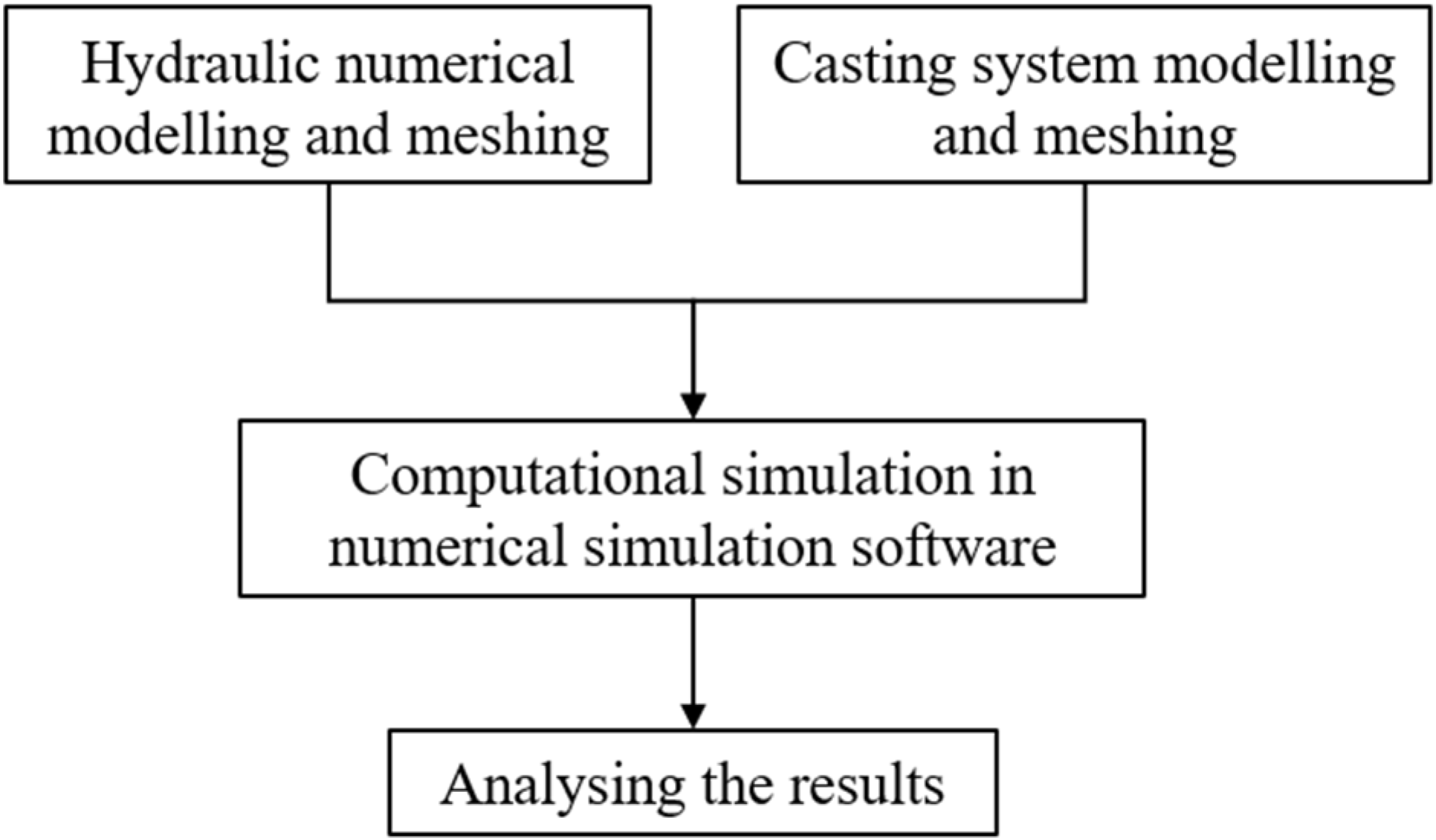
2. Numerical Simulation

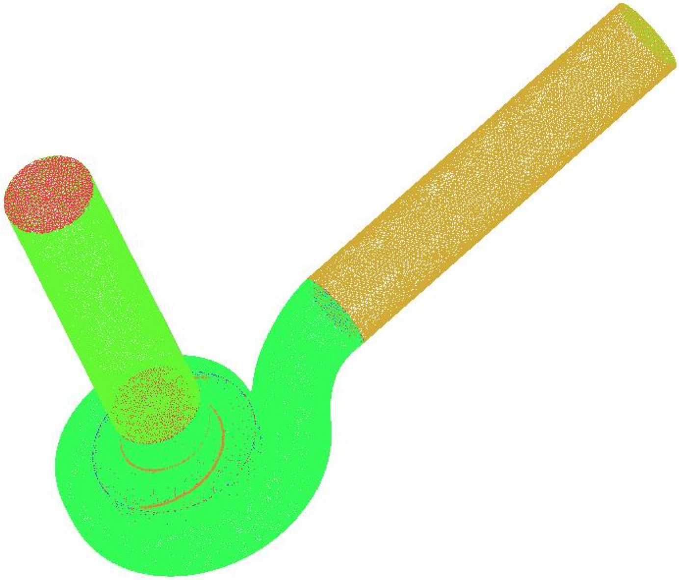
2.1. Computational Modelling and Mesh Segmentation

This paper takes a single-stage single-suction spiral centrifugal pump as the object of study, and the design performance parameters of the pump are as follows: flow rate Q = 220 m3/h, head H = 15 m, rotational speed n = 1450 r/min, specific rotation ns = 170, impeller inlet diameter D1 = 175 mm, impeller outer diameter D2 = 290 mm, outlet width b2 = 45 mm. The main calculation domain of the spiral centrifugal pump included the impeller flow channel, worm gear flow channel, suction chamber, and diffusion pipe. The model calculation domain is the main water body of the pump, including the inlet, impeller, volute, diffusor, and outlet.
To allow the full development of turbulence in the inlet and outlet, both the inlet and outlet sections of the pump are extended by a certain length for the calculation. To adapt to the complex turbulence inside the pump, the impeller and volute use a more flexible unstructured mesh, while the inlet and outlet sections use a structured mesh, as shown in Figure 2.

2.2. Mesh-Independent Investigation

For RANS simulations, due to the introduction of the turbulence model, the mean values of the coefficients did not change much after the mesh reached a certain density, and further encoding did not lead to a more accurate solution. Therefore, in order to exclude the influence of the number of meshes on the computational results, a mesh-independent investigation is required before further studies. In this paper, five sets of meshes were selected for mesh-independent validation, and the external properties were calculated and the results are shown in Figure 3.
The results show that with the increase in the number of meshes, head and efficiency gradually leveled off. Taking into account the computational resources and costs, the number of meshes of the computational model in this paper is 3,354,124, and the near-wall mesh is refined using the boundary layer to ensure that the Y+ < 20.

2.3. Boundary Conditions

In this paper, the k-omega turbulence model is used for the solution based on ANSYS CFX 2021 R1. The inlet and outlet boundary conditions are defined as flow inlet and free outflow, respectively, the reference pressure is set as the standard atmospheric pressure, and the inlet flow velocity is calculated for various working conditions. On this basis, the solid wall surface was defined as a no-slip boundary condition, and the roughness of the wall surface was set to 0.025 mm. In addition, 1 degree of impeller rotation was set to be 1 time step, and each time step was 0.00011494 s, and each rotation period was 360 steps. A sample of 5 rotation cycles was selected for the experiment, and the total acquisition time of the sample was 0.206892 s.

2.4. Casting Simulation

For the accurate simulation of the casting process of the spiral centrifugal pump and the analysis of casting defects, this paper chooses the casting process numerical simulation software ANYCASTING 6.0. Investment casting is able to produce components with complex geometries and detailed structures, which is particularly important for impellers that require a delicate design. Impellers often have complex curved surfaces and internal passages, and investment casting can achieve very high dimensional accuracy and surface finish, reducing the need for subsequent machining. Compared with other casting processes such as sand casting, shell casting, metal casting, etc., investment casting has obvious advantages in the production of parts with high precision, high complexity, and high performance requirements. Therefore, for centrifugal pump impellers requiring high precision and high surface quality, investment casting is the most ideal choice. The casting process involved choosing the investment casting; as shown in Figure 4, the mesh establishment of the whole casting system and the filling process was used, and the total number of meshes was 18,303,912 (242 × 198 × 382). ANYCASTING 6.0 is a simulation system specially designed for various casting processes, capable of simulating and analyzing the pouring, heat transfer, and solidification processes of the casting. The specific parameters of the casting process are set as follows: material selection AISI American Iron and Steel Institute 17-4 PH (precipitation-hardening stainless steel), shell temperature 800 °C, pouring temperature 1500 °C, pouring speed 30 cm/s, and pouring diameter 50 mm. The figure shows the simulation of the filling process, and the total filling time was 4.9157 s.

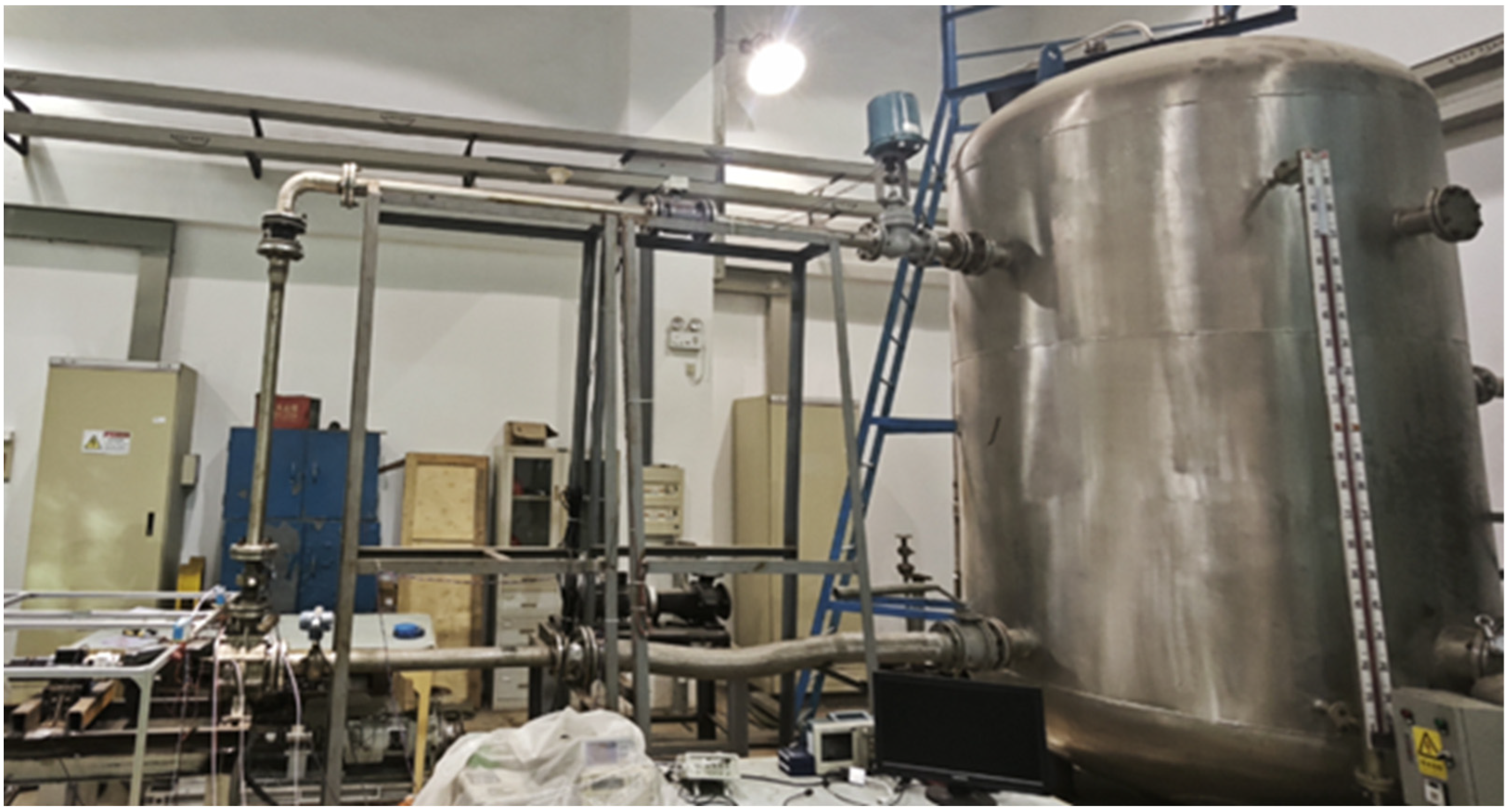
2.5. Experimental Verification

To verify the accuracy of the numerical simulation, the initial model was tested on a closed-loop test rig at the Fluid Mechanics Laboratory of Jiangsu University. Figure 5 shows the test setup. As can be seen from Figure 6, the curve obtained from the external characteristic test had the same trend as the curve obtained from the simulation prediction, the head curve was almost the same at the large flow point and the design condition, and the calculated value of the small flow point was slightly higher than the simulated value, but the relative error was not more than 3.3% of the total head; the simulated value of each point in the efficiency curve was slightly lower than the experimental value, but the relative error was also not more than 5.4%. Therefore, confirming the reliability and feasibility of numerical simulation, the selected computational model can accurately predict the pump hydraulic performance.

3. Significant Factors Screening

In this paper, seven factors are selected to clarify the structural parameters that significantly affect the performance of the spiral centrifugal pump, based on the Plackett–Burman experimental design of resolution III of the main geometric parameters of the spiral centrifugal pump using the software of MINITAB 21.
The Plackett–Burman design is an efficient screening design that can screen for factors that have a significant effect on performance with a small number of trials. This is particularly useful for complex systems such as screw centrifugal pumps with multiple factors and levels. Compared to the full factorial design, the Plackett–Burman design requires significantly fewer experiments, thus saving experimental resources and time. This is a significant advantage for engineering problems that require a large number of experiments and data collection.
In contrast to other methods, such as the full factorial design, although it is able to comprehensively study all factors and their interactions, providing a complete model and accurate conclusions, the number of experiments increases rapidly with the number of factors and levels, which is costly and time-consuming, and in particular it is not applicable when there are a large number of factors. As for the Latin square design, the advantage is that it is suitable for eliminating the ranks effect in the experiment and reduces the confounding error of the experiment. The disadvantages are also obvious: it has limited applicability, can only handle experiments with three factors, and is not applicable when the complexity increases.
Therefore, in this paper, we chose the Plackett–Burman design of the experimental method based on MINITAB 21 software with resolution III, which can efficiently identify the main geometric parameters affecting the performance of spiral centrifugal pumps in the screening stage, save experimental resources and time, and provide concise and clear analysis results.
The parameters are impeller inlet diameter DJ, outer diameter D2, blade thickness S, outlet width b2, blade outlet angle β2, shroud radius R2, and hub radius R1 as variables, and head, efficiency, and residual melting modulus as response quantities. The residual melting modulus is the ratio of the surface area of the residual melting to the volume of the residual melting. The smaller the value in the casting, the smaller the number of isolated molts in the casting, the smaller the tendency of the casting to have defects like shrinkage and blowholes, and the better the quality of the casting.
Seven geometric parameters describing the structure of the spiral centrifugal pump were selected for screening, as shown in Table 1, and the tests were performed 12 times. The analysis of the results was carried out using MINITAB 21 software, using the 12 sets of parameters obtained for the three corresponding indicators, head, efficiency, and residual melting modulus.
Table 2 shows the corresponding p-values of each P-B test factor; the smaller the p-value, the greater the effect on head, efficiency, and residual melting modulus. The top four p-values from small to large are S, b2, D2, and β2 according to the magnitude of the p-value in the head P-B test. Similarly, the top four p values from small to large in the efficiency P-B test are b2, S, β2, and D2, and according to the residual melting modulus P-B test, the top four p values from small to large are S, D2, b2, and DJ. The structural geometry parameter with the highest number of intersections in its top two positions was selected based on the significance analysis of the P-B experiment in the table as S, D2, b2, and DJ. According to the significance analysis of the P-B experiment in the table, the first two structural geometry parameters with the highest number of overlaps were selected as significant influencing factors; these were the blade thickness S and the outlet width b2. Therefore, the factors to be used in the next impact study are these two geometric parameters.

4. Results and Analysis

4.1. Effect of Blade Thickness

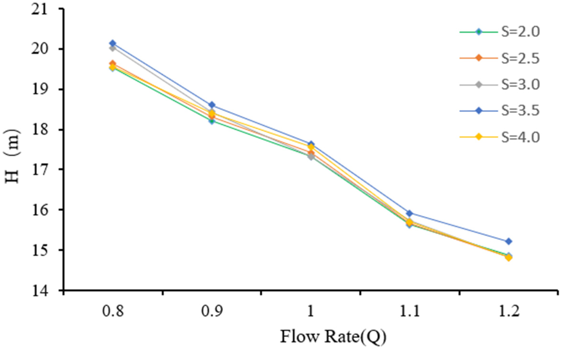
4.1.1. Hydraulic Performance

In order to analyze the effect of blade thickness on the head and efficiency of the spiral centrifugal pump without changing other parameters, the above model is used for simulation, where the impeller inlet diameter D1 = 175 mm, the impeller outer diameter D2 = 290 mm, and the outlet width b2 = 45 mm. The value of the blade thickness S is taken according to the position from the shroud to the hub in accordance with the law from small to large, respectively, (2~4), (2.5~4.5), (3~5), (3.5~5.5), (4~6) (mm). Considering the actual working condition of the pump, the range of the value of the working condition is 0.8~1.2 Q. Figure 7 and Figure 8 show the efficiency and head curves of the five different blade thicknesses.
From the curve comparison, it can be seen that in most cases, pump head and efficiency will improve with increasing blade thickness. At the flow rate of 0.8–0.9 Q, the efficiency of S = 3 is lower than that of S = 4. Under the design condition of 220 m3/h, the S = 3 blade achieves the highest efficiency of 84.52%, which is an increase of 3.16% in efficiency and 0.32 m in head compared to the S = 2 blade. Overall efficiency and head are low at both S = 2 and S = 2.5. From the results of the hydraulic performance, when the blade thickness is increased, the outlet pressure of the impeller and the head of the pump are increased. However, when the blade thickness is increased to 4 mm, both head and efficiency began to show a declining tendency. This is due to the increase in blade thickness causing an eddy current losses increase, resulting in partial energy loss.

4.1.2. Velocity Field

Three different models, S = 2, S = 3.5, and S = 4, were selected for an analysis of their internal flow fields at design conditions in order to investigate the potential effects of different blade thickness models on head and efficiency. Figure 9 shows the relative velocity distribution of the impeller, extracted from the center section. Inside the impeller, there are two significant low-velocity regions, located at the center of each of the two blade pressure surfaces and extending towards the suction surface. At the same time, the maximum relative velocity within the impeller occurs close to the central outlet of the impeller channel. The area of the low-velocity zone at the blade pressure surface was at its maximum for S = 2, when comparing the different models. However, the area of the low velocity zone of the pressure surface was significantly reduced when the blade thickness was increased by 1.5 mm. Increasing the thickness of the blades reduces the formation of vortices within the impeller, improves the distribution of the fluid flow around the blades, and allows the fluid to pass more uniformly through the blades.
When the blade thickness is 4 mm, the area of the low-velocity region of the pressure surface increases again. Therefore, an excessive increase in blade thickness may cause some negative effects, such as vortex and secondary flow generation and an increase in vortex losses. Taken together, a balance needs to be struck in blade design to stabilize the flow field within the impeller and improve efficiency.

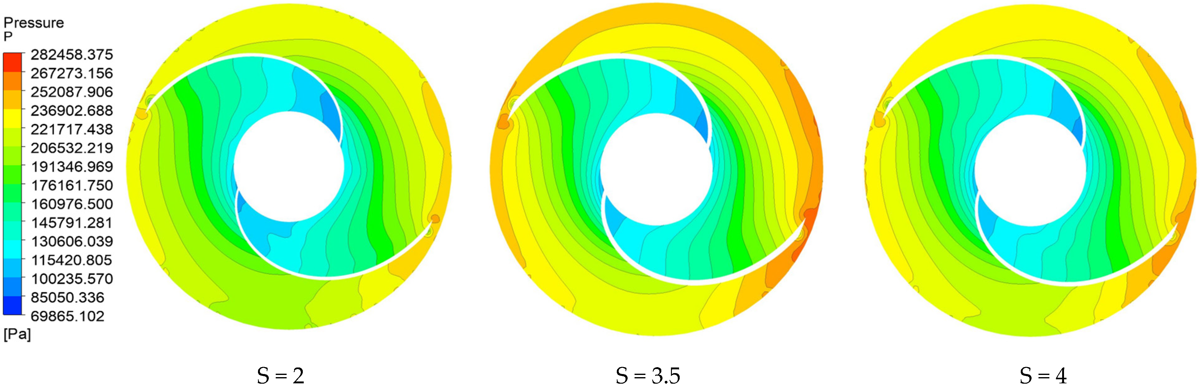
4.1.3. Pressure Field

Figure 10 shows the static pressure distribution in the center of each impeller model at different blade thicknesses. From the figure, it can be seen that low pressure areas appear near the head suction surface at the impeller inlet position for all three model sets. As the design of the volute is helical, the liquid in the volute rotates along the helical path of flow, resulting in an unequal distribution of static pressure in each flow path of the volute, manifested by the static pressure rising from the inlet to the outlet of the volute; the static pressure of the blade pressure surface is significantly greater than that of the blade suction surface.
A side-by-side comparison shows that the pressure distribution inside the impeller is more homogeneous with S = 3, while the blade outlet pressure is higher than S = 2. This is due to the fact that increasing the blade thickness increases the work loading by the impeller on the fluid. However, when the blade thickness was further increased to S = 4, the impeller outlet pressure decreased, indicating a reduction in work loading by the blades on the fluid. and an excessive increase in blade thickness may cause an increase in axial vortices, resulting in greater resistance when the fluid flows through the blades. Therefore, careful balancing of the blade thickness is necessary in design to ensure the stability of the flow field inside the impeller and to improve efficiency.

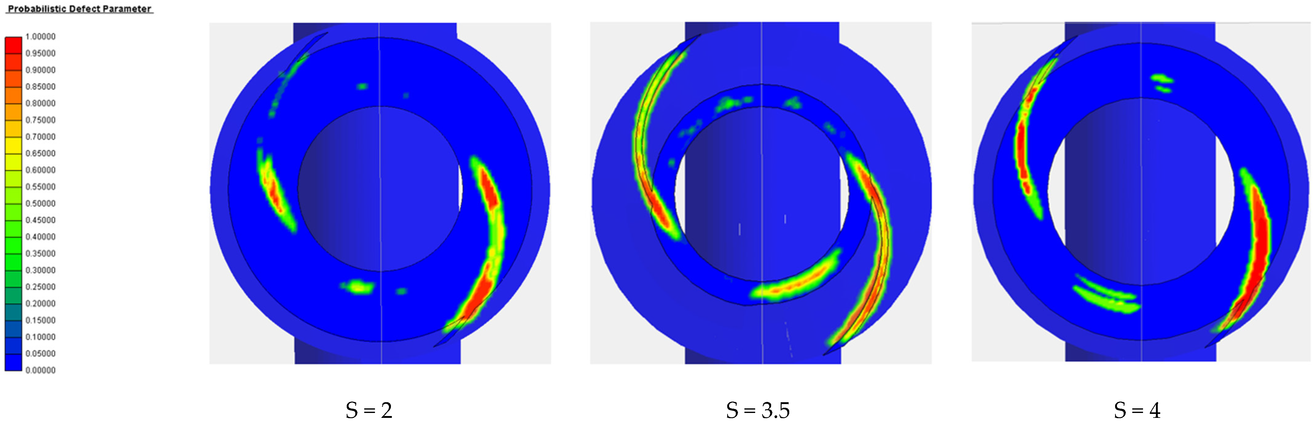
4.1.4. Casting Defects

The 3D model of the entire impeller casting system was drawn in NX12.0 and imported into ANYCASTING 6.0. Figure 11 shows the distribution of defects on the impeller surface. Figure 12 shows the distribution of defects in the impeller center section.
It was observed that the main casting defects were concentrated at the impeller inlet and the suction side of the blades, with the area where the blades meet the rear cover plate being more prone to casting defects. As the thickness of the blade increases, so does the potential for casting defects. Analysis of the previous phenomenon shows that blade solidification starts at the thinner part of the wall thickness and cools towards the thicker part of the wall thickness. Due to the relatively small size of the sprue on the blade, when the high temperature melt enters the cavity and is affected by cooling, the temperature drops, viscosity increases, and fluidity is weakened, which slows the subsequent filling of the melt and then causes incomplete filling of the mold, ultimately leading to the formation of defects such as shrinkage holes and shrinkage loosening during late cooling. The latter phenomenon is due to the increase in blade thickness, which cannot be compensated for in time at thicker points.

4.2. Effect of Discharge Width

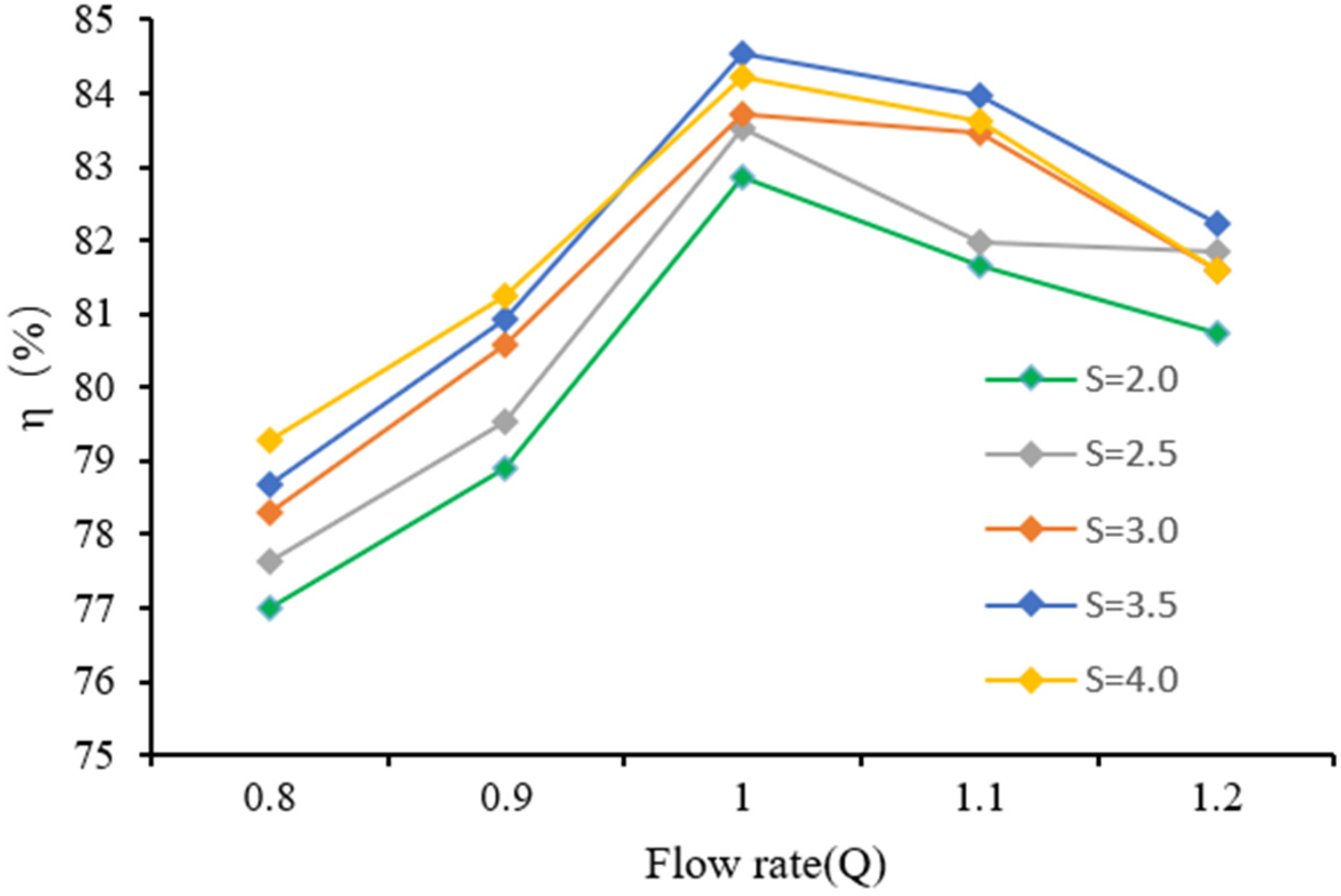
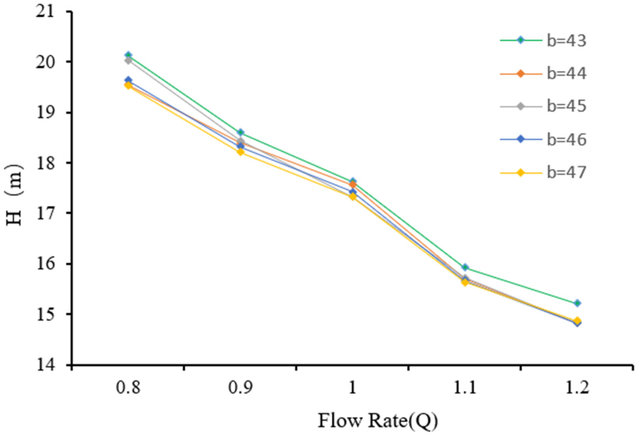
4.2.1. Hydraulic Performance

To analyze the effect of outlet width on the performance of spiral centrifugal pumps, the spiral centrifugal pump model mentioned earlier was used for calculation. During simulation, other parameters were kept constant, and only the outlet width of the impeller of the spiral centrifugal pump was changed. The outlet widths b2 were taken as 43, 44, 45, 46, and 47 mm, respectively. In this case, the inlet width of the worm model was adjusted according to the variation in the outlet width of the impeller, as a way to exclude the influence of the gap between the worm and the impeller on the performance of the centrifugal pump.
Figure 13 shows the efficiency curve and head curve of a spiral centrifugal pump at different flow ratios under five outlet widths. As above, considering the actual operating conditions of the pump, the performance curve of the pump with a flow ratio range of 0.8~1.2 was taken.
From Figure 14, it can be seen that below the design flow rate, the efficiency of the spiral centrifugal pump is significantly higher at b2 = 43 and b2 = 44. When the design flow is higher, it can be seen that b2 = 47 and b2 = 46 achieve higher efficiency, with the highest efficiency of 84.1% achieved at b2 = 47. From this, it can be seen that increasing the blade thickness below the design flow rate and at the design point will reduce the efficiency of the pump, while increasing the blade thickness above the design flow rate will improve the performance of the pump. The reason is that increasing the width of the impeller outlet may cause the working point of the pump to deviate from the design point, thereby affecting efficiency. Increasing the outlet width may make the pump more suitable for handling larger flow rates, causing the design point of the pump to shift on the performance curve, and thereby improving efficiency at the design point, resulting in the highest efficiency occurring above the design flow rate.
As can be seen from the graph, as the width of the impeller outlet continues to increase, the overall head of the pump shows a decreasing trend. The main reason is that the pressure decreases, and a wider outlet may reduce the pressure formed by the liquid in the pump, thereby affecting the head. According to Bernoulli’s law, there is an inverse relationship between pressure and velocity. Therefore, as the outlet width increases, the velocity of the liquid inside the pump may increase, while the pressure decreases, resulting in a decrease in head.

4.2.2. Pressure Field

Figure 15 shows the static pressure distribution in the middle sections of the impeller and volute of various spiral centrifugal pump models with different outlet widths. As shown in the figure, as the width of the impeller outlet increases, the pressure at the impeller outlet, volute outlet, and separator decreases. The pressure reduction is more significant at the impeller outlet and volute outlet. The reason for this is to increase the outlet width of the impeller, allowing more liquid to pass through. The flow rate of the liquid passing through the impeller increases, reducing the pressure formed by the liquid inside the pump, resulting in a decrease in head.

4.2.3. Casting Defects

Figure 16 shows the distribution of casting defects in the middle sections of each model with different impeller outlet widths. The darker the color, the higher the residual melt modulus, and the greater the possibility of defects such as shrinkage porosity and porosity occurring during the actual casting process. As the width of the impeller outlet increases, the residual melt modulus at the connection between the trailing edge of the blade and the rear cover plate will also be larger, while the residual melt modulus on the blade surface near the impeller outlet will decrease. This is because during the casting process, liquid metal must flow through the connection between the blade and the rear cover plate. If the outlet width is large, the flow path of the liquid metal becomes more complex, causing collisions at the connection and resulting in uneven flow, vortices, or turbulence, increasing the risk of casting defects. Increasing the width of the impeller outlet extends the surface of the blade, making it easier for liquid metal to flow inside the blade surface and forming a smoother surface.

5. Conclusions

  • In this paper, considering the hydraulic performance and casting molding of the spiral centrifugal pump, the head, efficiency, and residual melt modulus are taken as the response quantities, and using the Plackett–Burman experimental design of resolution III, the blade thickness S and outlet width b2 are the significant influencing factors.
  • In the authors’ opinion, in terms of blade thickness, under the small flow condition, the blade thickness can be increased appropriately to improve efficiency, and under the large flow condition, it is necessary to increase the blade thickness cautiously; 3.5 mm is optimal under this model. Increasing the blade thickness will increase the probability of casting defects and reduce the casting molding rate and impeller outlet width; increasing the impeller outlet width will lead to a decrease in head. At a small flow rate increase, the impeller outlet width efficiency will decline, and when the flow rate reaches the design flow rate above, the efficiency will rise. The author believes that increasing the impeller outlet width will lead to design point offset. Increasing the impeller outlet width leads to an increase in residual melt at the connection and a decrease in residual melt on the blade surface, and casting defects are likely to occur at the connection between the blade and the rear cover plate.

Author Contributions

Conceptualization, C.W. and Z.L.; methodology, Y.L.; software, Z.L.; investigation, C.W.; resources, Z.S.; testing, D.Y. All authors have read and agreed to the published version of the manuscript.

Funding

This research was funded by the Open Research Subject of Key Laboratory of Fluid Machinery and Engineering (Xihua University), Sichuan Province (No. LTJX-2023002), Taizhou Science and Technology Plan Project (No. 23gyb23), Zhejiang Provincial Natural Science Foundation of China (No. LY24E090004).

Data Availability Statement

The relevant data can be found in this article.

Acknowledgments

Thanks to Shen Zhenhua for providing the test pump from his Postdoctoral Program.

Conflicts of Interest

The authors declare no conflicts of interest.

References

  1. Wu, C.; Fan, Y. Study on internal structure dynamics of spiral centrifugal pump. Water Pump Technology. 2020, 6, 18–23+40. [Google Scholar]
  2. Guan, X.F. Overview. In Handbook of Modern Pump Technology; Aerospace Press: Beijing, China, 1995; pp. 6–7. [Google Scholar]
  3. Liu, X.C.; Han, W.; Li, R.N. Effect of blade wrap angle on cavitation performance of spiral centrifugal fuel pump. Hydraulic Pneum. Seal. 2022, 42, 75–81. [Google Scholar]
  4. Zhou, F.; Li, Y.H.; Li, Q.F. Analysis of flow-solid coupling forces in spiral centrifugal pumps under different working conditions. Hydraul. Pneum. Seal. 2023, 43, 19–22. [Google Scholar]
  5. Thi, H.; Viet, A.T. Optimization of the Meridional Plane Shape Design Parameters in a Screw Centrifugal Pump Impeller. KSFM J. Fluid Mach. 2021, 24, 15–25. [Google Scholar]
  6. Thi, H.; Ujjwal, S.; Young, D. Hydraulic and Suction Performances of the Screw Centrifugal Pump for Live Fish Transfer According to Impeller Blade Inlet Shapes. Korean Soc. Fluid Mech. 2022, 25, 16–25. [Google Scholar]
  7. Thi, H.; Ujjwal, S.; Young, D. Effect of impeller inlet and passage meridional shapes on screw centrifugal pump performance. In Proceedings of the Spring Meeting of the Korean Society of Mechanical Engineers, Seoul, Republic of Korea, 3–7 November 2020. [Google Scholar]
  8. Wu, C.G.; Fan, Y.Z. Research on gas-liquid two-phase flow in spiral centrifugal pump. Water Supply Drain. 2020, 56, 973–978+985. [Google Scholar]
  9. Ren, W.L.; Zhao, Z.F.; Hao, Z.R. Influence of medium viscosity on internal flow characteristics of spiral centrifugal pumps. Mar. Eng. 2021, 43, 241–246. [Google Scholar]
  10. Egorkina, N.; Petrov, A. The method of constructing the cavitation characteristics of a screw centrifugal pump using the methods of hydrodynamic modeling. Mater. Sci. Eng. 2019, 492, 12–15. [Google Scholar] [CrossRef]
  11. Emilio, E.; Paladino; Rafael, F.L.; De, C.; Josiane, W.; Thales, C.; Lavoratti, E. Theoretical and experimental analysis of multiphase twin-screw pumps operating in serial arrangement. J. Pet. Sci. Eng. 2022, 216, 110–130. [Google Scholar]
  12. Yasushi, T.; Kazuhiro, T. Influence of meridian shape on screw-type centrifugal pump performance. In Proceedings of the ASME 2002 Fluids Engineering Division Summer Meeting, Montreal, QC, Canada, 14 July 2002. [Google Scholar]
  13. Bai, Y.; Zhang, H.; Huang, L.; Gao, X. Numerical simulation and optimization of impeller die casting based on ProCAST. Therm. Process. Technol. 2021, 50, 71–75. [Google Scholar]
  14. Samraj, A.; Ponnusamy, R.; Ganesan, V. Numerical and experimental approach to eliminate defects in al alloy pump- crank case processed through gravity die casting route. Mater. Today Proc. 2020, 37, 1772–1777. [Google Scholar]
  15. Yao, L.J.; Zhao, H.H.; Zhong, K.S. Research on closed impeller rapid casting technology based on ProCAST and 3D printing technology. Mech. Electr. Eng. 2015, 32, 1166–1169+1191. [Google Scholar]
  16. Zhang, F.; Zhang, J.; Xi, L.; He, Z.; Wang, Y. Numerical simulation study of aluminium alloy impeller investment casting. Foundry Technol. 2016, 37, 805–808. [Google Scholar] [CrossRef]
  17. Xu, Q.; Wang, X.; Wu, S. Numerical Simulation of Bubble Migration in Liquid Titanium Alloy Melt During Vertical Centrifugal Casting Process. J. Harbin Inst. Technol. 2019, 6, 91–96. [Google Scholar]
  18. Zhang, X.; Hu, B.B.; Feng, Y.M. Multi-objective optimization design of spiral centrifugal pump based on RBF neural network and DECIMO algorithm. J. Drain. Lrrigation Mach. Eng. 2022, 40, 667–673. [Google Scholar]
  19. Wu, C.S.; Zhang, W.Q.; Wu, P. Effects of blade pressure side modification on unsteady pressure pulsation and flow structures in a centrifugal pump. J. Fluids Eng. 2021, 143, 111208. [Google Scholar] [CrossRef]
  20. Zhang, L.W.; Wu, C.S. Influence of blade thickness distribution on flow structure and performance of centrifugal pump. Fluid Mach. 2023, 51, 19–25+65. [Google Scholar]
  21. Mousavi, N.; Kothapalli, G.; Habibi, D.; Lachowicz, S.W.; Moghaddam, V. A real-time energy management strategy for pumped hydro storage systems in farmhouses. J. Energy Storage 2020, 32, 101928. [Google Scholar] [CrossRef]
  22. Gulich, J.F. Effect of Reynolds number and surface roughness on the efficiency of centrifugal pump. J. Fluid Eng. 2003, 125, 670–679. [Google Scholar] [CrossRef]
  23. Ulanicki, B.; Kahler, J.; Coulbeck, B. Modeling the Efficiency and Power Characteristics of a Pump Group. J. Water Resour. Plan Manag. 2008, 134, 88–93. [Google Scholar] [CrossRef]
  24. Liu, Z.; Zhou, L.; Tang, H.; Wang, Z.; Zhao, F.; Ji, X.; Zhang, H. Primary instability, sensitivity and active control of flow past two tandem circular cylinders. Ocean. Eng. 2024, 294, 116863. [Google Scholar] [CrossRef]
  25. Léopold, G.; Nadot, Y.; Billaudeau, T.; Mendez, J. Influence of artificial and casting defects on fatigue strength of moulded components in Ti-6Al-4V alloy. Fatigue Fract. Eng. Mater. Struct. 2015, 38, 1026–1041. [Google Scholar] [CrossRef]
Figure 1. Research process.
Water 16 01598 g001
Figure 2. Pump mesh.
Water 16 01598 g002
Figure 3. Calculation results of hydraulic performance under different mesh numbers.
Water 16 01598 g003
Figure 4. Casting model mesh and mold-filling process.
Water 16 01598 g004
Figure 5. Closed-loop test rig.
Water 16 01598 g005
Figure 6. Comparison between test and simulation.
Water 16 01598 g006
Figure 7. Efficiency curves for 5 different blade thicknesses.
Water 16 01598 g007
Figure 8. Head curves for 5 different blade thicknesses.
Water 16 01598 g008
Figure 9. Comparison of velocity fields with different blade thicknesses.
Water 16 01598 g009
Figure 10. Comparison of pressure fields with different blade thicknesses.
Water 16 01598 g010
Figure 11. Comparison of casting defects on the surfaces of impellers with different blade thicknesses.
Water 16 01598 g011
Figure 12. Comparison of casting defects in the middle sections of impellers with different blade thicknesses.
Water 16 01598 g012
Figure 13. Efficiency curves for different impeller outlet widths.
Water 16 01598 g013
Figure 14. Head curves of different impeller outlet widths.
Water 16 01598 g014
Figure 15. Static pressure distribution in the middle sections of spiral centrifugal pumps with different impeller outlet widths.
Water 16 01598 g015
Figure 16. Comparison of casting defects in the middle section of impellers with different impeller outlet widths.
Water 16 01598 g016
Table 1. Plackett–Burman design factors and levels.
ItemFactorsLow Level (−)High Level (+)
ADJ (mm)170180
BD2 (mm)295305
Cb2 (mm)4347
Dβ2 (°)2024
ES (mm)2 (shroud)
4 (hub)
4 (shroud)
6 (hub)
FR2 (mm)4244
GR1 (mm)8789
Table 2. Comparison of p values of influencing factors.
FactorsP (H)P (η)P (R)
DJ (mm)0.1130.5390.098
D2 (mm)0.0360.0450.025
b2 (mm)0.0270.0160.047
β2 (°)0.0670.0350.248
S (mm)0.0220.0310.039
R2 (mm)0.4890.2640.532
R1 (mm)0.2300.6230.364
Disclaimer/Publisher’s Note: The statements, opinions and data contained in all publications are solely those of the individual author(s) and contributor(s) and not of MDPI and/or the editor(s). MDPI and/or the editor(s) disclaim responsibility for any injury to people or property resulting from any ideas, methods, instructions or products referred to in the content.

