Article

A Study on the Transient Characteristics of the Power-Off Transition Process of a Double-Volute Centrifugal Pump

1
Hunan Provincial Water Resources Development and Investment Co., Ltd., Changsha 410007, China
2
School of Electrical and Power Engineering, Hohai University, Nanjing 211100, China
3
Hunan Water Resources and Hydropower Survey, Design, Planning and Research, Co., Ltd., Changsha 410007, China
*
Author to whom correspondence should be addressed.
Water 2024, 16(12), 1707; https://doi.org/10.3390/w16121707
Submission received: 16 May 2024 / Revised: 9 June 2024 / Accepted: 13 June 2024 / Published: 15 June 2024
(This article belongs to the Special Issue Advances in Hydrodynamics of Water Pump Station System)

Abstract

:
A double-volute centrifugal pump is a very important pump type; the internal flow field of a centrifugal pump will change drastically during the transition process of power failure, which will affect the safety and stability of the pump’s operation. In this paper, the CFD numerical simulation method is used, and the UDF procedure is developed to realize the continuous update of the impeller speed at each time step. The working parameters, such as the torque and flow rate at the instantaneous moment, are obtained through the sequential iteration of each small step, and a numerical simulation of the power-off transient is carried out on a double-volute centrifugal pump; additionally, the changes in the external characteristic parameters and the internal flow field of the centrifugal pump are analyzed in detail. The results show that the double-volute centrifugal pump experienced four different modes after power failure, namely pump mode, braking mode, turbine mode, and runaway mode, and the absolute values of the runaway speed and runaway flow rate are 1.465 times and 1.21 times the initial values, respectively. Through the analysis of the flow field in different regions, the change processes of the generation, development, and disappearance of the vortex at each position of the centrifugal pump are obtained, and the change and development processes of the internal velocity gradient of the centrifugal pump are obtained. In addition, it is found that the high-speed area located in the second volute runner is larger than that of the first volute runner because the second volute runner is shorter and narrower than the first volute runner.

1. Introduction

A double-volute centrifugal pump is a very important pump type, which uses a splitter to divide the traditional single volute runner into two volute runners, so it has better hydraulic efficiency and head, it can better balance the radial force on the impeller, and it can effectively suppress pressure pulsation [1,2]. Li Q et al. [3] investigated the entropy generation of single and double-volute molten salt pumps, and they discovered that the double-volute molten salt pump experiences a less radial hydraulic force. In general, the double-volute scheme reduces energy loss and ensures better structural stability. Shim H S et al. [4,5] numerically calculated the hydraulic efficiency and radial force of double-volute centrifugal pumps with different volute geometries and found that a reasonable double-volute structure can effectively reduce the radial force on the impeller. Khalifa A E et al. [6] found that there is a relationship between pressure fluctuation and vibration in a double-volute centrifugal pump and found an effective way to reduce the vibration in the double-volute pump. Xiao R et al. [7] found that adding a reasonable splitter structure in a single-volute double-suction pump can make the double-volute double-suction pump maintain its original hydraulic performance and reduce the radial force of the impeller. Yang J et al. [8] calculated and analyzed the transient flow during the start-up process of the double-volute centrifugal pump and found that the pressure fluctuation on the outside of the splitter was relatively stable relative to the inside of the splitter. Yang M et al. [9] numerically simulated the pressure pulsation characteristics and radial force of the impeller of the double-volute centrifugal pump and found that there was obvious pressure pulsation in the double-volute pump.
In the process of power failure and during the shutdown and start-up of the pump, the internal flow field will change drastically, which will affect the safety and stability of the pump’s operation. At present, some progress has been made in the internal transient flow of centrifugal pumps under transient operating conditions. In the 1980s, Tsukamoto et al. [10,11] systematically studied the transient transition process of a small volute centrifugal pump during the rapid start-up and shutdown process, and they found that because of the existence of pulsating pressure, the dimensionless head coefficient was much higher than the calculated value under a quasi-steady state. Chalghoum I et al. [12] theorized transient flow during centrifugal pump start-up. The effects of the start-up time, impeller diameter, number of blades, and blade height on pressurization were analyzed. The numerical results show that the pressure increment is inversely proportional to the start-up time. Tanaka T et al. [13] conducted experiments and CFD studies on the transient characteristics of centrifugal pumps during rapid start-up, and the results showed that the transient characteristics in the experiment were greater than the quasi-steady state change at the beginning of the transient period and then gradually approached the quasi-steady state change. Zhou D et al. [14] revealed variations in parameters such as the speed, flow, torque, and pressure at the measuring point with time through the numerical simulation of the axial flow pump device model during runaway caused from power failure. Wang W et al. [15] analyzed the unsteady internal flow characteristics and time-frequency characteristics of pressure fluctuation of a pump turbine in turbine mode (PAT) during power failure, and the results showed that the flow field between the blades was extremely unstable under braking conditions, and the main frequency of volute pressure fluctuation was related to the rotation speed, which was mainly caused by dynamic and static interaction. Wang W [16] et al. studied the pressure pulsation characteristics of a mixed-flow pump under turbine and runaway modes on an open test bench and analyzed the frequency domain characteristics of pressure pulsation based on FFT (Fourier Frequency Transform), and they found that in order to avoid pressure pulsation under runaway mode, the mixed-flow pump is best operated under small flow conditions such as those in a hydraulic turbine. Feng J et al. [17] simulated the power-off process of the centrifugal pump, and the results showed that the characteristic curves and runaway parameters of the pump predicted by the numerical simulation were in good agreement with the experimental results. The transient process after power failure mainly goes through four working modes: pump, brake, turbine, and runaway. Dong W et al. [18] studied the internal flow characteristics of centrifugal pumps under two linear start-up schemes, 0.1 s and 0.3 s, and found that the vorticity distribution of the 0.3 s start-up scheme was more regular, and the slender high-vorticity region was only distributed near the blade side. Zhang Y L et al. [19] established a closed-loop pipeline system including a centrifugal pump to achieve self-coupling solving, which revealed the transient characteristics of the centrifugal pump during shutdown and provided a good reference for the transient behavior of other impeller machinery.
When the pump unit is shut down due to sudden power failure or maloperation, it will eventually enter runaway mode, and when the pump unit is running in runaway mode, some parts of the pump unit may be damaged due to the mass imbalance of the rotating body and the hydraulic instability inside the unit [20]. More and more scholars have begun to conduct experiments and numerical simulation studies on the runaway mode of the pump unit [21,22]. Kan K et al. [23] analyzed in detail the flow characteristics and energy loss of the internal flow field during the runaway process of an axial flow pump unit. Wang G [24] et al. conducted an experimental study on the hydraulic characteristics of the inertial tank after the failure of the pump power and analyzed the influence of structural parameters, including CPD and the transition section, on the hydraulic characteristics of the inertial tank. Yang F et al. [25] conducted runaway characteristic tests on multiple groups of pump systems, and the measurement results showed that the runaway speed of the unit was different under different blade angles and increased with the increase in blade angles.
The accidental shutdown of a pumping station unit caused by power failure is a huge threat to the safe operation of the pumping station. Due to safety, financial, or technical constraints, some pump transient processes cannot be evaluated experimentally. In order to ensure the safe and stable operation of a pump unit in daily life, it is necessary to study the transient flow of the centrifugal pump after power failure. In this paper, the power-off transition process of the double-volute centrifugal pump is simulated by introducing the UDF procedure, and the transient change process of the external characteristics and internal flow field of the double-volute centrifugal pump are analyzed and revealed. This study provides a certain theoretical basis for the safe operation of a pumping station.

2. Numerical Methodology

2.1. Three-Dimensional Modeling of Centrifugal Pump

The centrifugal pump model is mainly composed of the intake pipe, impeller, double volute, and outlet diffusion section, as shown in Figure 1. The design parameters of the double-volute centrifugal pump are shown in Table 1. The specific speed used in this study is defined as follows:
n s = 3.65 N d Q d H d 0.75
where n s , N d , Q d , and H d denote the specific speed, design rotational speed, design flow rate, and design head, respectively.

2.2. Mesh Generation

In order to obtain more accurate numerical simulation results, this paper performs hexahedral structured meshing of each part of the double-volute centrifugal pump and encrypts the local mesh of key parts such as the double-volute tongue and the watershed around the runner blades. A schematic view of the grid of the individual components is shown in Figure 2, and the grid around an impeller blade is shown in Figure 3. Grid independence verification based on head and efficiency parameters is shown in Figure 4. When the number of grids is greater than 8.2 million, the efficiency value and head value tend to be stable. Therefore, the total number of calculated grid cells in the fluid area of the entire centrifugal pump is 8202648, and the number of grid cells for each component is listed in Table 2.

2.3. Setting of Boundary Conditions

In this paper, the transient calculation and analysis of the power-off transition process of a centrifugal pump are carried out based on CFD numerical simulation, and the SST k-ω turbulence model is selected. Compared to the k-ε model, the SST k-ω model can better deal with the transport of turbulent shear stress in the reverse pressure gradient and separation boundary layer. The centrifugal pump unit has a strong reverse pressure gradient, flow separation, reflux, and other abnormal flow phenomena during the shutdown process, so the SST k-ω model is used to calculate the subsequent transition process [26,27].
The inlet is adopted as the pressure inlet boundary condition, and the outlet is adopted as the pressure outlet boundary condition. The impeller is defined as a dynamic grid area. SIMPLEC is used for the pressure and velocity coupling algorithm; the pressure term in the calculation process adopts the second-order format, and the turbulent kinetic energy term and convection term are both in the second-order upwind style. The time step of the transient simulation is set to 4.5 × 10⁻⁴ s, which represents the time it takes for the impeller to rotate by 4 degrees. The number of iterations during each time step is set to 20, considering the influence of gravity, and the user-defined function (UDF) is used to calculate and control the angular speed of the impeller area during the entire shutdown process.
During power failure, the impeller speed and torque are determined by the angular momentum balance equation [28] represented by Equation (2):
M t M g = J d ω d t
where M t   is the resultant torque acting on the impeller, N·m; M g   is the drag torque, N·m; J   is the moment of inertia of the impeller of the centrifugal pump, kg·m2; and ω is the angular velocity, rad/s.
When the centrifugal pump is suddenly powered off, the drag torque is quickly reduced to zero, M g = 0, that is, the rotation angular velocity of the impeller at any time is shown in Equation (3):
ω i + 1 = ω i + M t i J × t
where t is the time step of the simulation calculation, and the angular velocity ω i and torque M t i at the ith moment can be obtained to iteratively calculate the speed of the next moment so as to realize the continuous update of the impeller speed at each time step. The sequential iteration of each small step is carried out to obtain working parameters such as the torque and flow rate at the instantaneous moment so as to realize the whole process calculation of the power-off transient.

2.4. Validation of Numerical Methods

In order to verify the accuracy of the numerical simulations, tests were carried out on a high-precision test bench, and the characteristic parameters of the pumps were obtained; the test bench is shown in Figure 5. The test process and methods strictly followed the international standard IEC 60193 [29]. By changing the speed of the pump to adjust the flow rate, the test data under multiple sets of pump conditions with different flow rates were measured, and Figure 6 shows the comparison of the simulation and experimental characteristic parameters, including the head (H), efficiency (η), and power (P). From the graph, it can be observed that the calculated value deviates from the experimental value. Under the condition of a small flow rate, the calculated values of the head, power, and efficiency are lower than the experimental values. Under the condition of a large flow rate, the calculated values of the head and power are higher than the experimental values, and the efficiency is lower than the experimental value. The errors are all within 5%, and they could have been caused by subtle geometric differences between the simulated model and the physical test model, including gaps that were overlooked during the simulation. In general, the results of the numerical calculations are basically consistent with the testing data, so the method of numerically simulating the transient power-off process of the centrifugal pump is reliable.

3. Results

3.1. Variation of External Characteristics

In order to more intuitively and clearly observe the variation in each external characteristic parameter of a centrifugal pump with time, the three values of torque, flow rate, and speed are dimensionless. Three relative values are introduced, which are the relative value of torque ( M r e l ), the relative value of the flow rate ( Q r e l ), and the relative value of speed ( N r e l ), where the subscripts t and 0 represent the instantaneous value and the initial value, respectively, as shown in Equation (4):
M r e l = M t / M 0 Q r e l = Q t / Q 0 N r e l = N t / N 0
As shown in Figure 7, the centrifugal pump has experienced four working modes, namely pump, brake, turbine, and runaway, during the power failure process. Under the pump mode (t = 0.212 s), the centrifugal pump is in the steady-state operation state under the design working condition during the 0–0.1 s period. The accident power failure occurs at 0.1 s, the parameters decrease rapidly, the relative value of the speed decreases by about 45%, the torque decreases to about 23.6% of the initial value, and the flow rate drops to 0 at t = 0.212 s. Then, it enters the braking mode, and the braking time is about 0.148 s (t = 0.212–0.36 s), the reverse flow rate begins to appear in the centrifugal pump and increases, the torque reaches the trough at t = 0.237 s, and then it begins to rise gradually. Under the action of reverse flow, the speed decreases faster than that of the pump under the action of reverse flow, and the speed drops to 0 at t = 0.36 s. As the direction of the rotation of the impeller changes, the centrifugal pump enters the turbine mode (t = 0.36–0.886 s), and the torque reaches its peak at t = 0.42 s, at which time M r e l = 1.02. Due to the influence of its own inertia, the flow rate decreases with the increase in speed after t = 0.531 s, and the speed, N r e l , gradually increases from 0 and then decreases slightly, finally reaching runaway speed. At t = 0.732 s, the reverse speed reaches the maximum value, and then because the centrifugal pump has experienced a small fluctuation from the turbine working condition to the hydraulic turbine dynamic condition and then to the hydraulic turbine working mode, the torque has a small fluctuation in a short time near 0. When the torque is stable at about 0 fluctuations, it enters a stable runaway mode (t > 0.886 s). At this time, the torque, flow rate, and rotational speed tend to be stable values. The absolute value of the speed is 1.465 times of the design rotational speed, and the absolute value of the flow rate is 1.21 times of the design flow rate, that is, the runaway speed is −2168.2 r/min, and the runaway flow rate is −0.38841 m3/s.

3.2. Evolution of Internal Flow

3.2.1. Flow State of Intake Pipe

In this section, the flow field inside the inlet pipe is studied by analyzing the streamline and velocity distribution of the intake pipe, as shown in Figure 8.
It is known from Figure 8a that when the flow rate of the centrifugal pump is 0, the streamline in the inlet pipe is relatively stable as a whole. But the streamline in the intake pipe and the inlet area of the impeller begins to rotate, indicating that the flow state in the inlet pipe is about to be unstable. When the speed of the impeller drops to 0, combined with Figure 8b, the straight cone pipe section close to the impeller begins to appear as an unstable vortex. The high flow velocity area is mainly concentrated in the wall surface of the straight cone pipe section. When the impeller reverses and enters the turbine mode, the swirl movement inside the intake pipe gradually increases. As shown in Figure 8c, the vortex of the straight cone section moves towards the elbow section and creates a new vortex in the straight cone section, and the high flow velocity area also moves towards the wall of the elbow section. Then, the maximum reverse flow is reached. As shown in Figure 8d, the original large vortex developed into several small vortices and began to move towards the diffusion pipe section, and the flow velocity of the pipe wall decreased. As shown in Figure 8e, with the continuous increase in the reversal speed, the previous small vortices gradually moved outward and, at the same time, produced new vortices in the straight cone pipe section. The high-speed area at the straight cone pipe wall reappeared. As shown in Figure 8f, in the stable runaway mode, there was a large range of vortices on the inside of the straight cone pipe section and the elbow pipe section, and some large vortices moved to the inlet of the intake pipe.

3.2.2. Flow State of Double Volute and Outlet

In order to better understand the content of this section, Figure 9 marks the locations of the tongue, the splitter, the first volute runner, and the second volute runner.
Figure 10 illustrates the velocity and streamline distribution in the double-volute and outlet diffusion section at various times. As can be seen in Figure 10a, when the flow rate of the centrifugal pump is 0, the centrifugal pump enters the braking mode. The flow regime of the double-volute area and the outlet diffusion section is very complex and disordered, a large number of vortices are located in the outlet diffusion section, and the vortex in the double-volute area is mainly located at the tongue and the tail end of the splitter. Due to the influence of dynamic and static interference, the high-speed area is mainly located at the beginning of the tongue and the splitter, and the speed at the tongue is higher. When the impeller speed drops to 0, it begins to enter the turbine mode; as seen in Figure 10b,c, the flow regime of the double volute area and the outlet diffusion section becomes relatively stable, the vortex disappears, and the high-speed area appears in a small area at the tail of the impeller blade. Because the second volute runner is shorter and narrower than the first volute runner, the area of the high-speed area located in the second volute runner is 30–50% larger than the first volute runner. This is when the maximum value of the reverse flow rate is reached. As shown in Figure 10d, the high-speed area develops from a block-like distribution to a continuous band-like distribution. As shown in Figure 10e,f, the high-speed area develops into a discontinuous band-like distribution divided by blades as the reversal speed increases until it reaches the runaway speed.

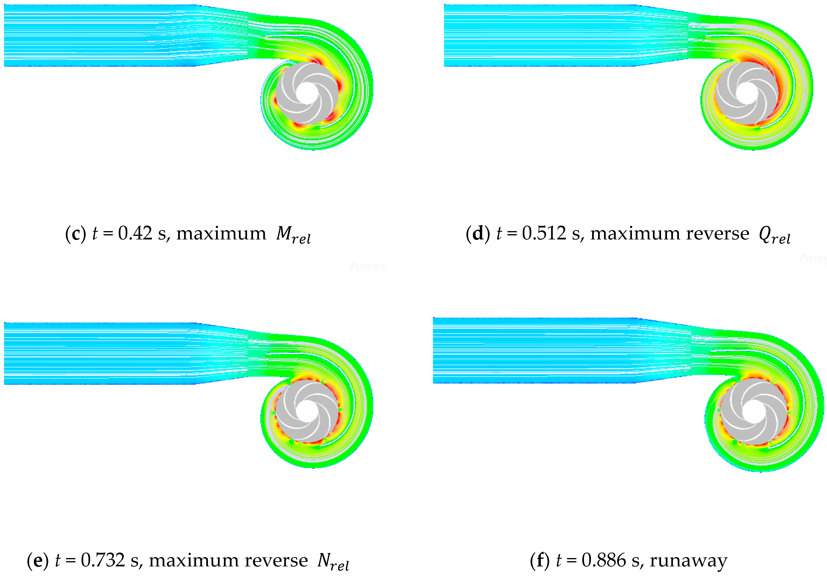
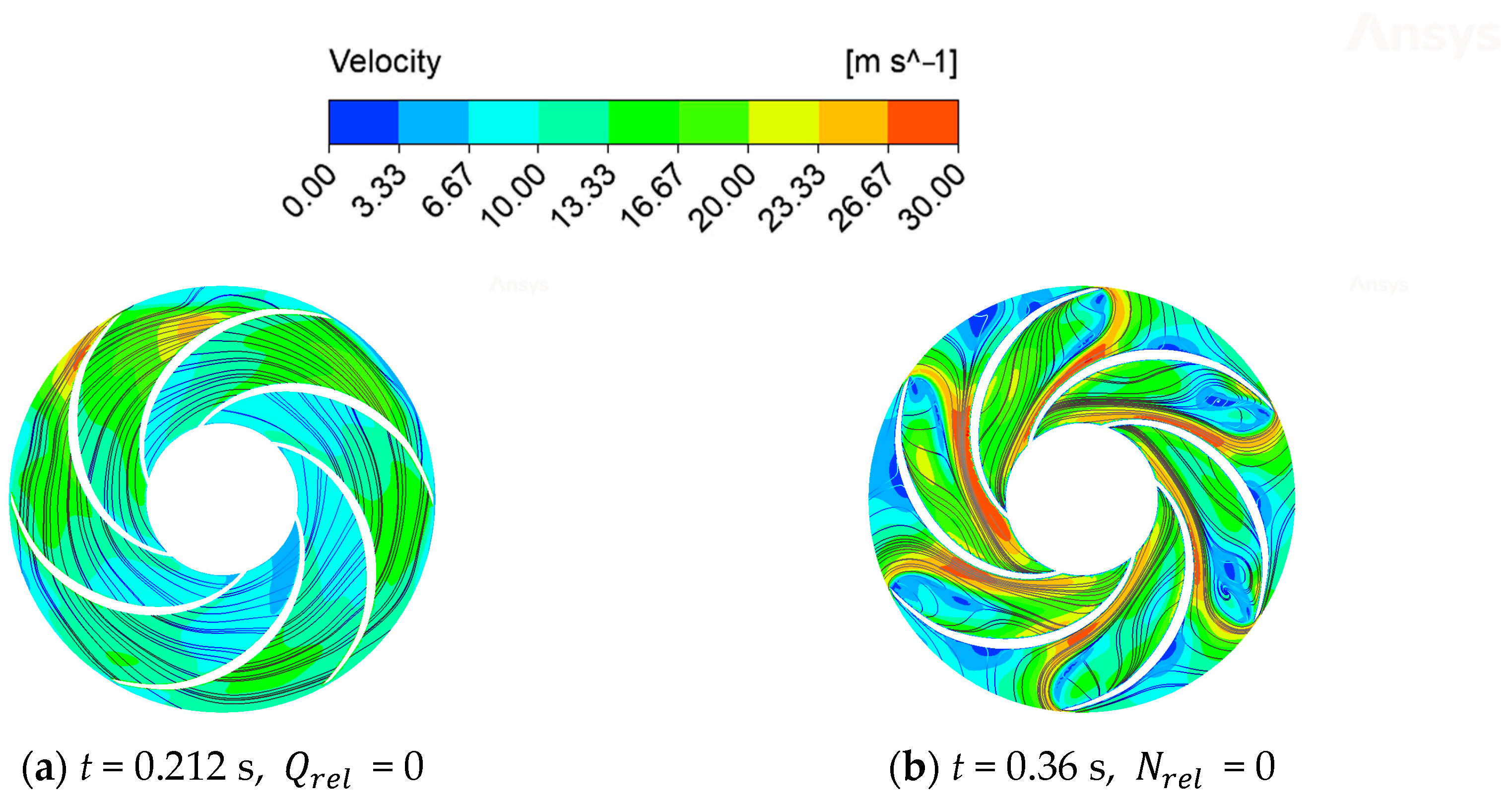
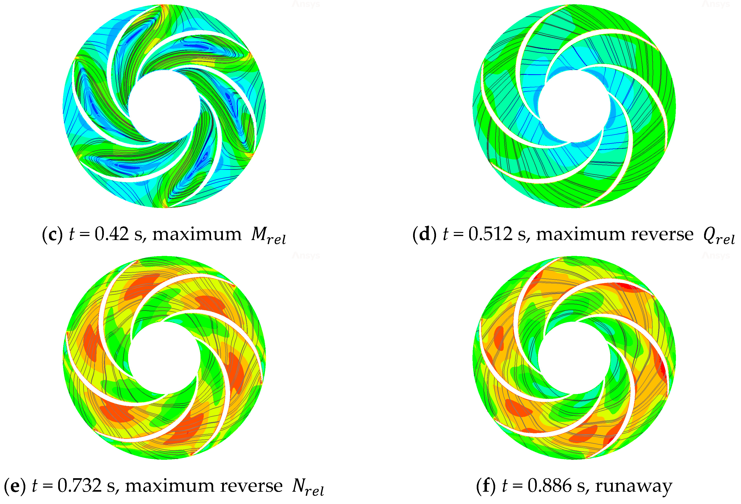
3.2.3. Flow State of Impeller

The impeller is the most important component of the centrifugal pump, and the direction of the impeller will change during the transient process of stopping the pump. In order to facilitate the description of the suction surface and pressure surface of the impeller and the inlet and outlet of the impeller during the transition process, the initial pump working conditions are taken as the reference. That is, the interface between the impeller and the intake pipe is defined as the impeller inlet, the interface between the impeller and the volute is defined as the impeller outlet, the convex surface of the blade is the pressure surface, and the concave surface of the blade is the suction surface. Figure 11 shows the velocity and streamline distribution of the central section of the impeller at various times.
As can be seen in Figure 11a, the speed and flow rate of the centrifugal pump continue to decrease after power failure. When the flow rate of the centrifugal pump is 0, the streamline in the impeller area is relatively stable, and the speed gradient is not obvious. But there is a small high-speed area near the tongue due to the influence of dynamic and static interference, and there is a small low-speed area at the entrance of the impeller, which may be the place where the vortex of the inlet pipe is generated. When the speed of the impeller drops to 0, as seen in Figure 11b, the flow regime in the impeller area changes drastically. It can clearly be seen that there is a large number of vortices at the tail of the impeller suction surface, and the velocity gradient in the impeller area has a drastic difference. There are both high-speed and low-speed areas; the high-speed area is mainly concentrated in the front end of the impeller pressure surface, and the low-speed area is located in the small area of the rear end of the impeller pressure surface and the center of the vortex at the tail of the impeller suction surface. When the impeller begins to reverse into the turbine mode. As shown in Figure 11c, the vortex begins to move towards the front end of the impeller suction surface, the velocity gradient at the front end of the impeller pressure surface decreases significantly, and the low-speed area also moves with the vortex towards the impeller inlet. When the maximum value of reverse flow is reached. As shown in Figure 11d, the vortex in the runner area gradually disappears due to the gradual decrease in the impact of the water flow on the blades. The internal flow regime gradually stabilizes, the velocity gradient is no longer obvious, and only a small low-speed area is located in the runner inlet area. As shown in Figure 11e, with the continuous increase in the reverse speed, the streamline is no longer smooth, and there is a tendency to rotate but no new vortex is formed. The high-speed area reappears, which is located in a leafless zone near the middle of the impeller pressure surface. As shown in Figure 11f, the internal flow regime does not change significantly in the stable runaway mode, and the high-speed area begins to move towards the tail of the impeller suction surface.

4. Conclusions

In this paper, the numerical simulation of the power-off transient of the centrifugal pump is carried out by using the CFD numerical simulation and the UDF procedure that introduces the torque balance equation to control the speed of the centrifugal pump. The changes in the external characteristic parameters and internal flow field of the centrifugal pump are analyzed in detail, and the following conclusions are drawn:
(1)
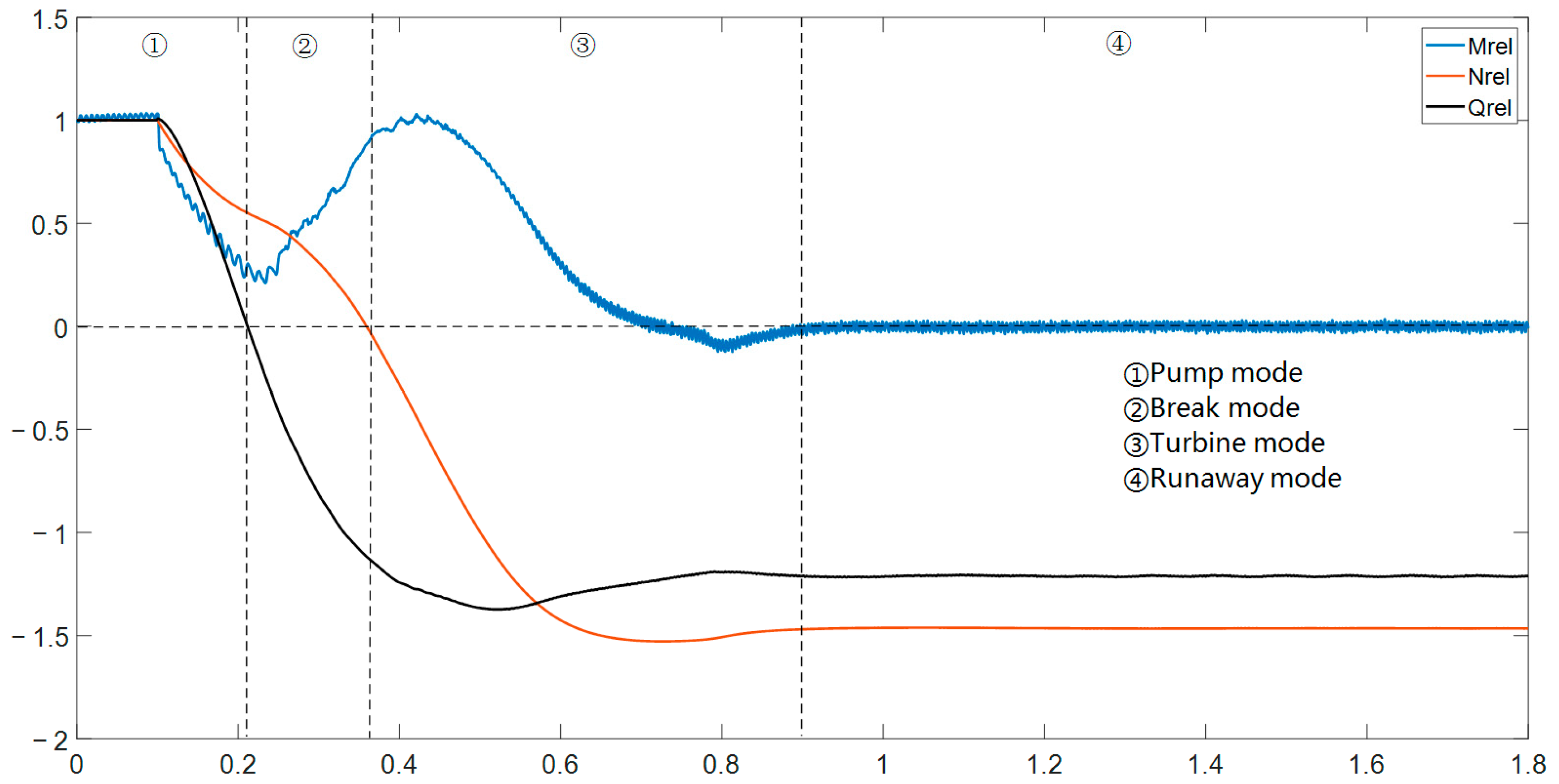
After the double-volute centrifugal pump is powered off, it experienced four different modes, namely pump mode, braking mode, turbine mode, and runaway mode. The impeller torque, flow rate, and speed of the centrifugal pump underwent drastic changes after power failure and finally became stable under runaway mode. The absolute values of the runaway speed and the runaway flow rate are 1.465 times and 1.21 times the initial values, respectively.
(2)
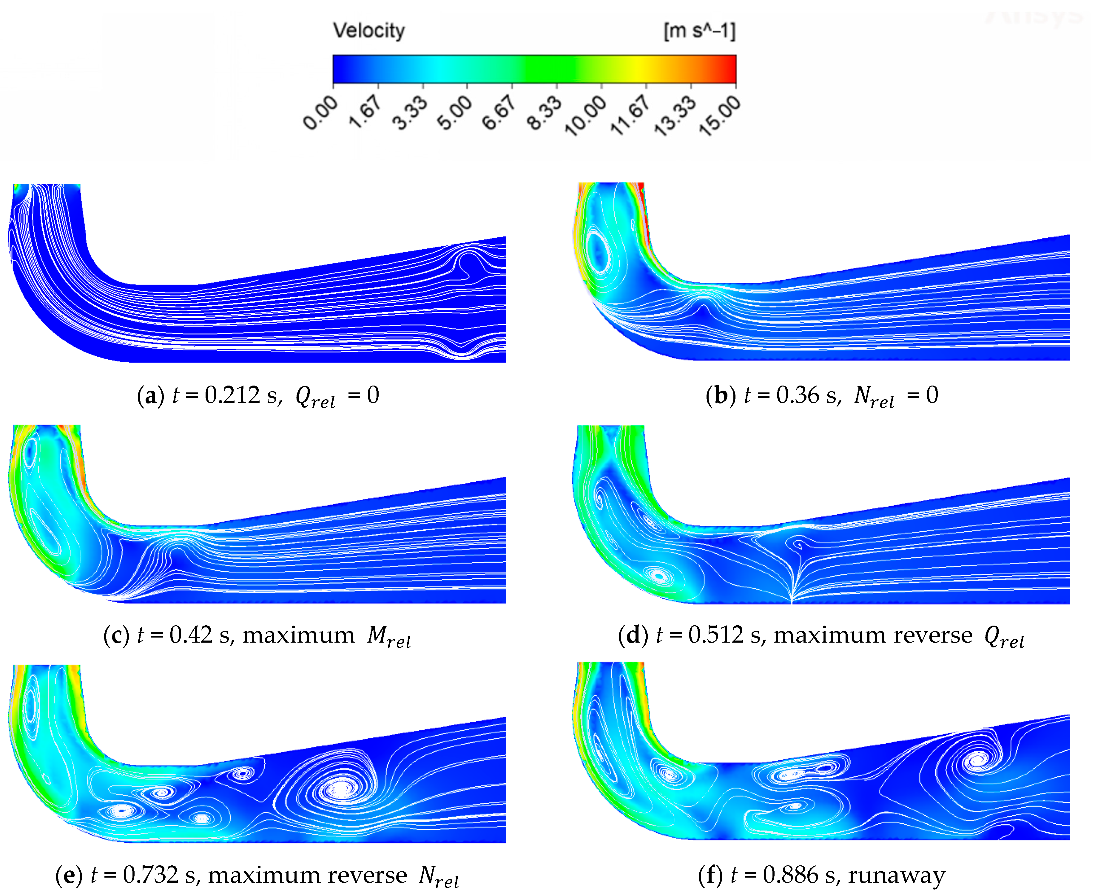
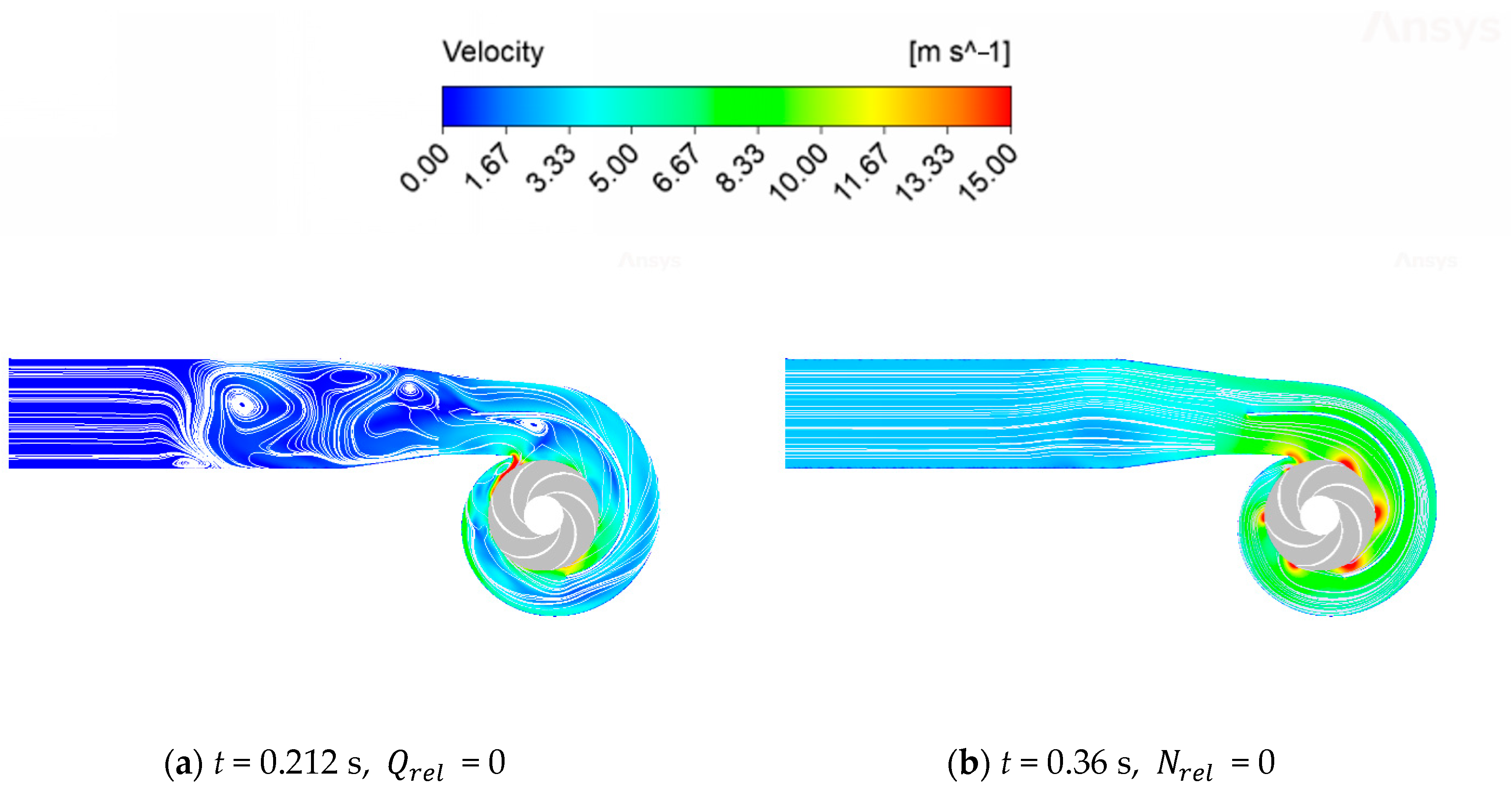
Due to the huge change in the direction of speed and flow rate in the process of power failure, the flow regime inside the whole centrifugal pump became very complicated, and a large number of unstable flows of secondary flow, reflux, and flow separation were produced in the flow runner. Through the analysis of the flow field in the intake pipe area, the impeller area, the double-volute area, and the outlet diffusion section, we can see the change process of the generation, development, and disappearance of the vortex at each position of the centrifugal pump. We can also see the change and development process of the internal speed gradient of the centrifugal pump.
(3)
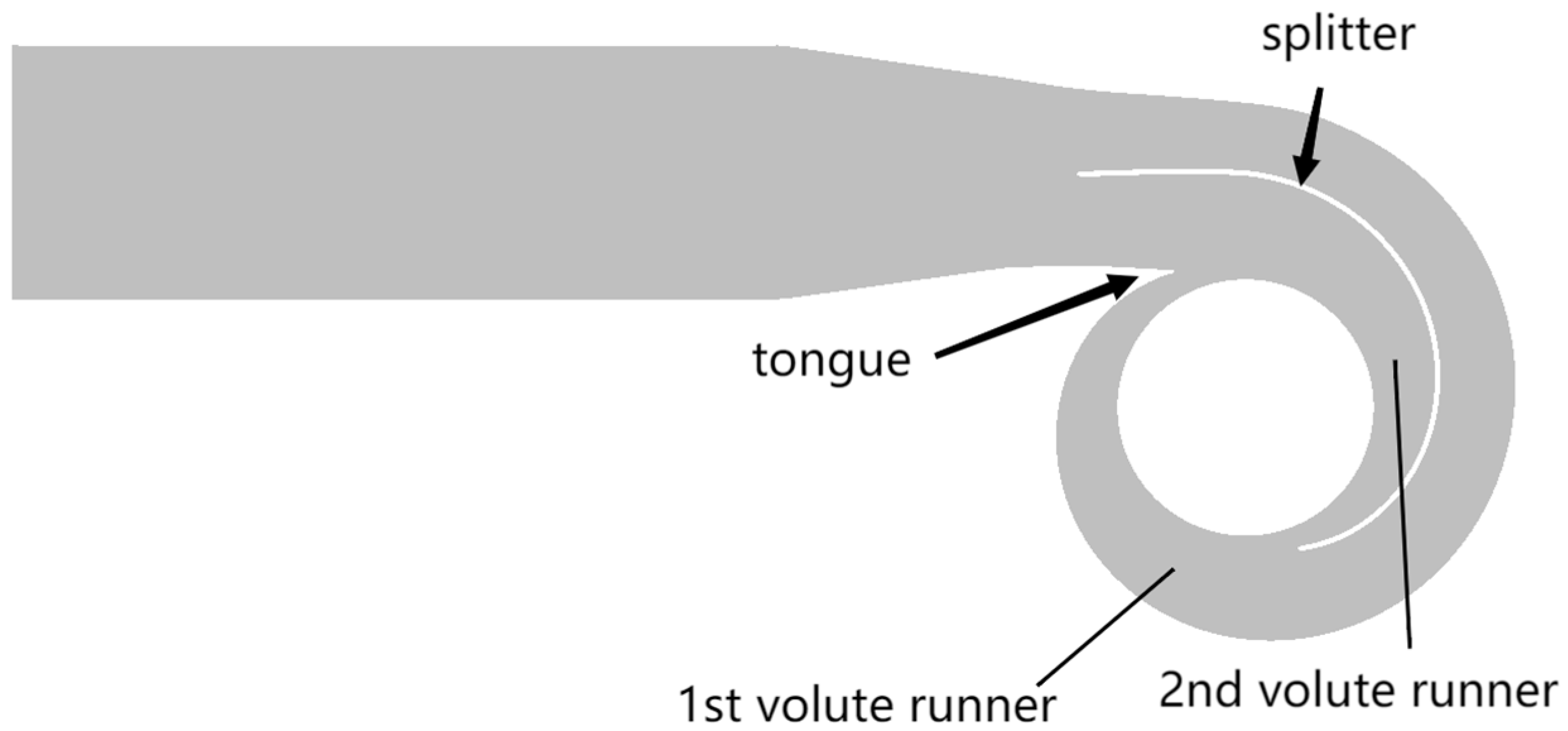
For the double-volute centrifugal pump, not only the dynamic and static interference of the tongue, but also the dynamic and static interference at the splitter will cause certain changes in the internal flow regime of the centrifugal pump. Because the second volute runner is shorter and narrower than the first volute runner, the high-speed area located in the second volute runner will be larger than that of the first volute runner.

Author Contributions

L.L.: Conceptualization, Formal Analysis, and Methodology. Z.R.: Software, Data Curation, and Writing—Original Draft Preparation. Z.W.: Investigation, Validation, and Methodology. W.Z.: Resources, Visualization, and Supervision. S.L.: Project Administration, Software, and Visualization. J.D.: Validation and Writing—Review and Editing. C.Y.: Funding Acquisition and Writing—Review and Editing. M.D.: Investigation and Software. All authors have read and agreed to the published version of the manuscript.

Funding

This project was supported by the Key Program of the National Natural Science Foundation of China (No. 52339006) and the National Natural Science Foundation of China (No. 52271275).

Data Availability Statement

The data presented in this study are available on request from the corresponding author.

Conflicts of Interest

Author Lifeng Lu, Wenjie Zhou, and Jin Dai were employed by the company Hunan Provincial Water Resources Development and Investment Co., Ltd.; and Zhongzan Wang, Siwei Li, and Mengfan Dang were employed by the company Hunan Water Resources and Hydropower Survey, Design, Planning and Research, Co., Ltd. The remaining authors declare that the research was conducted in the absence of any commercial or financial relationships that could be construed as a potential con-flict of interest.

References

  1. Zhang, X.; Yuan, S.; Zhang, J. Effects of spiral volute type on performance of high specific speed centrifugal pump. J. Drain. Irrig. Mach. Eng. 2017, 35, 25–31. [Google Scholar]
  2. Zhang, Z.; Wang, F.; Yao, Z.; Xiao, R. Effect of Double-Volute Casing on Impeller Radial Force for a Large Double-Suction Centrifugal Pump. In Fluids Engineering Division Summer Meeting; American Society of Mechanical Engineers: New York, NY, USA, 2015; Volume 57212, p. V001T33A016. [Google Scholar]
  3. Li, Q.; Zhang, R.; Xu, H. Effects of volute structure on energy performance and rotor operational stability of molten salt pumps. J. Appl. Fluid Mech. 2023, 16, 1615–1626. [Google Scholar]
  4. Shim, H.S.; Kim, K.Y. Numerical investigation on hydrodynamic characteristics of a centrifugal pump with a double volute at off-design conditions. Int. J. Fluid Mach. Syst. 2017, 10, 218–226. [Google Scholar] [CrossRef]
  5. Shim, H.S.; Afzal, A.; Kim, K.Y.; Jeong, H.S. Three-objective optimization of a centrifugal pump with double volute to minimize radial thrust at off-design conditions. Proc. Inst. Mech. Eng. Part A J. Power Energy 2016, 230, 598–615. [Google Scholar] [CrossRef]
  6. Khalifa, A.E.; Al-Qutub, A.M.; Ben-Mansour, R. Study of pressure fluctuations and induced vibration at blade-passing frequencies of a double volute pump. Arab. J. Sci. Eng. 2011, 36, 1333–1345. [Google Scholar] [CrossRef]
  7. Xiao, R.; Lu, T.; Wang, F. Influence of rib structure in double-volute centrifugal pumps on the impeller radial force. Nongye Jixie Xuebao (Trans. Chin. Soc. Agric. Mach.) 2011, 42, 85–88. [Google Scholar]
  8. Yang, J.; Zhou, R.; Chen, H.; Yu, T. Transient flow characteristics and pressure pulsation characteristics at splitter of double-volute centrifugal pump during startup. J. Jiangsu Univ. (Nat. Sci. Ed.) 2021, 42, 278–283. [Google Scholar]
  9. Yang, M.; Min, S.M.; Wang, F.J. Numerical simulation of pressure fluctuation and radial force in a double volute pump. Trans. Chin. Soc. Agric. Mach. 2009, 40, 83–88. [Google Scholar]
  10. Tsukamoto, H.; Ohashi, H. Transient Characteristics of a Centrifugal Pump During Starting Period. J. Fluids Eng. 1982, 104, 6–13. [Google Scholar] [CrossRef]
  11. Tsukamoto, H.; Matsunaga, S.; Yoneda, H.; Hata, S. Transient Characteristics of a Centrifugal Pump During Stopping Period. J. Fluids Eng. 1986, 108, 392–399. [Google Scholar] [CrossRef]
  12. Chalghoum, I.; Elaoud, S.; Akrout, M.; Taieb, E.H. Transient behavior of a centrifugal pump during starting period. Appl. Acoust. 2016, 109, 82–89. [Google Scholar] [CrossRef]
  13. Tanaka, T.; Takatsu, N. Transient Characteristics of a Centrifugal Pump at Rapid Startup; IOP Publishing Ltd.: Bristol, UK, 2019; Volume 240, p. 052016. [Google Scholar]
  14. Zhou, D.; Zhong, L.; Zheng, Y.; Mao, Y. Numerical simulation of transient flow in axial-flow pump unit model during runaway caused from power failure. J. Drain. Irrig. Mach. Eng./Paiguan Jixie Gongcheng Xuebao 2012, 30, 401–406. [Google Scholar]
  15. Wang, W.; Guo, H.; Zhang, C.; Shen, J.; Pei, J.; Yuan, S. Transient characteristics of PAT in micro pumped hydro energy storage during abnormal shutdown process. Renew. Energy 2023, 209, 401–412. [Google Scholar] [CrossRef]
  16. Wang, W.; Guo, H.; Zhang, C.; Shen, J.; Pei, J.; Yuan, S. Experimental investigation on pressure fluctuation characteristics of a mixed-flow pump as turbine at turbine and runaway conditions. J. Energy Storage 2022, 55, 105562. [Google Scholar] [CrossRef]
  17. Feng, J.; Ge, Z.; Zhang, Y.; Zhu, G.; Wu, G.; Lu, J.; Luo, X. Numerical investigation on characteristics of transient process in centrifugal pumps during power failure. Renew. Energy 2021, 170, 267–276. [Google Scholar] [CrossRef]
  18. Dong, W.; Fan, X.; Dong, Y.; He, F. Transient Internal Flow Characteristics of Centrifugal Pump During Rapid Start-Up. Iran. J. Sci. Technol. Trans. Mech. Eng. 2023. [Google Scholar] [CrossRef]
  19. Zhang, Y.L.; Zhu, Z.C.; Cui, B.L.; Li, Y.; Tao, R.H. Numerical simulation of unsteady flow in centrifugal pump during stopping period. J. Eng. Thermophys. 2012, 33, 2096–2099. [Google Scholar]
  20. Kan, K.; Zheng, Y.; Chen, H.; Zhou, D.; Dai, J.; Binama, M.; Yu, A. Numerical simulation of transient flow in a shaft extension tubular pump unit during runaway process caused by power failure. Renew. Energy 2020, 154, 1153–1164. [Google Scholar] [CrossRef]
  21. Walseth, E.C.; Nielsen, T.K.; Svingen, B. Measuring the dynamic characteristics of a low specific speed pump—Turbine model. Energies 2016, 9, 199. [Google Scholar] [CrossRef]
  22. Ye, C.; Tang, Y.; An, D.; Wang, F.; Zheng, Y.; van Esch, B.P.M. Investigation on stall characteristics of marine centrifugal pump considering transition effect. Ocean Eng. 2023, 280, 114823. [Google Scholar] [CrossRef]
  23. Kan, K.; Xu, Z.; Chen, H.; Xu, H.; Zheng, Y.; Zhou, D.; Muhirwa, A.; Maxime, B. Energy loss mechanisms of transition from pump mode to turbine mode of an axial-flow pump under bidirectional conditions. Energy 2022, 257, 124630. [Google Scholar] [CrossRef]
  24. Wang, G.; Wang, B.; Wen, J.; Tian, R.; Niu, Z.; Liu, X. Experimental study on the hydraulic characteristics of inertia tank after the failure of pump power. Ann. Nucl. Energy 2021, 151, 107885. [Google Scholar] [CrossRef]
  25. Yang, F.; Liu, C.; Tang, F.P.; Zhou, J.R. Experimental Study on Runaway Characteristics of Pump System; IOP Conference Series: Materials Science and Engineering; IOP Publishing: Bristol, UK, 2013; Volume 52, p. 022021. [Google Scholar]
  26. Menter, F.R. Two-equation eddy-viscosity turbulence models for engineering applications. AIAA J. 1994, 32, 1598–1605. [Google Scholar] [CrossRef]
  27. Mao, J.Y.; Yuan, S.Q.; Pei, J.; Zhang, J.F.; Wang, W.J. Applications of Different Turbulence Models in Simulations of a Large Annular Volute-Type Pump with the Diffuser; IOP Conference Series: Earth and Environmental Science; IOP Publishing: Bristol, UK, 2014; Volume 22, p. 022019. [Google Scholar]
  28. Fu, S.; Zheng, Y.; Kan, K.; Chen, H.; Han, X.; Liang, X.; Liu, H.; Tian, X. Numerical simulation and experimental study of transient characteristics in an axial flow pump during start-up. Renew. Energy 2020, 146, 1879–1887. [Google Scholar] [CrossRef]
  29. IEC 60193; Hydraulic Turbines, Storage Pumps and Pump-Turbines-Model Acceptance Tests. IEC: Geneva, Switzerland, 2019.
Figure 1. Three-dimensional model of double-volute centrifugal pump.
Water 16 01707 g001
Figure 2. Grid view of each component: (a) outlet, (b) double volute, (c) impeller, and (d) intake pipe.
Water 16 01707 g002
Figure 3. The grid around an impeller blade.
Water 16 01707 g003
Figure 4. Grid independence verification diagram.
Water 16 01707 g004
Figure 5. Test bench.
Water 16 01707 g005
Figure 6. Comparison of simulation and experimental characteristic parameters.
Water 16 01707 g006
Figure 7. Pump characteristic parameters during power failure.
Water 16 01707 g007
Figure 8. Streamline and velocity distributions in intake pipe at various times.
Water 16 01707 g008
Figure 9. Locations of the tongue, the splitter, the first volute runner, and the second volute runner.
Water 16 01707 g009
Figure 10. Streamline and velocity distributions in double volute and outlet at various times.
Water 16 01707 g010aWater 16 01707 g010b
Figure 11. Streamline and velocity distributions in impeller at various times.
Water 16 01707 g011aWater 16 01707 g011b
Table 1. Main parameters of centrifugal pump.
Parameter NameNumerical Value
Design flow rate, Qd (m3/s)0.321
Design head, Hd (m)40.3
Design rotational speed, Nd (r/min)1480
Specific speed, ns191.3
Impeller inlet diameter, D1 (mm)283.7
Impeller outlet diameter, D2 (mm)399.8
Number of impeller blades, Z16
Table 2. Number of grid cells for each component.
Component NameIntake PipeImpellerDouble VoluteOutlet Pipe
Number of grid cells921,7133,571,7143,563,816145,405
Disclaimer/Publisher’s Note: The statements, opinions and data contained in all publications are solely those of the individual author(s) and contributor(s) and not of MDPI and/or the editor(s). MDPI and/or the editor(s) disclaim responsibility for any injury to people or property resulting from any ideas, methods, instructions or products referred to in the content.

