Technical Note

Experimental Study on Upstream Water Level Rise of Submerged Rock Weirs

1
Key Laboratory of Hydraulic and Waterway Engineering of the Ministry of Education, Chongqing Jiaotong University, Chongqing 400074, China
2
College of River and Ocean Engineering, Chongqing Jiaotong University, Chongqing 400074, China
3
State Key Laboratory of Hydraulics and Mountain River Engineering, Sichuan University, Chengdu 610065, China
*
Author to whom correspondence should be addressed.
Water 2024, 16(15), 2136; https://doi.org/10.3390/w16152136
Submission received: 8 July 2024 / Revised: 25 July 2024 / Accepted: 25 July 2024 / Published: 28 July 2024
(This article belongs to the Topic Research on River Engineering)

Abstract

:
Rock weirs, typically created by the placement of loose rocks, are eco-friendly hydraulic structures used for raising the upstream water level, which has benefits for irrigation, shipping, and grade control. Although rock weirs are frequently submerged in rivers, few studies have systematically investigated their impacts on the upstream water level under submerged conditions. A series of flume experiments regarding this topic were conducted. Different flow discharges, tail-water depths, and void ratios were adopted in the experiments. The results show that (1) the submerged rock weirs primarily function to raise the upstream water level, while having a limited impact on the tail-water level; (2) for a given tail-water depth and void ratio, the upstream water level rise increases with increased discharge, although this response becomes insignificant as tail-water depth increases; (3) as void ratio increases, the upstream water level rise is expected to decrease for a given tail-water depth and discharge; and (4) based on the data and observations, a predictor including the effects of Froude number, submergence, and void ratio is proposed for estimating the upstream water level rise of submerged rock weirs. These results contribute to further understanding the hydraulic properties of rock weirs and are important for river training practices using rock weirs.

1. Introduction

Rock weirs are eco-friendly hydraulic structures typically created by the placement of loose rocks [1]. They usually span the full width of the channel to increase local flow resistance, thereby increasing the upstream water level, which is beneficial for irrigation, shipping, and grade control [2,3]. Also, rock weirs are more eco-friendly than solid weirs as they can improve river longitudinal connectivity [4], mimic heterogeneous habitats to support aquatic life [5], and promote hyporheic exchange to enhance water quality [6]. Consequently, rock weirs are widely used for training or restoring small- and medium-sized rivers [7]. Despite their popularity, the impact of rock weirs on the upstream water level is not yet well understood due to the complexity of structures formed by rocks (e.g., structural permeability [8,9]), limiting their application in river engineering.
In recent decades, many studies have been conducted to study the response of the upstream water level to the presence of rock weirs. In earlier works, many studies often simplified rock weirs as broad-crested weirs, using modified head–discharge relationships (e.g., modifying the discharge coefficient [10,11,12,13,14,15]) to estimate the upstream water level. Over the past decade, many studies specific to rock weirs were conducted. Holmquist-Johnson [16] experimentally studied the responses of water depth upstream of U-shaped rock weirs (in plan), proposing an empirical equation including the effects of weir geometry and normal water depth for predicting the upstream water depth. Thornton [17] investigated the impacts of W-, U-, and A-shaped rock weirs on the river water level using the experimental data from Meneghetti [18]; subsequently, an equation calculating the water level upstream for each type of rock weirs was proposed. Baki [19] numerically studied the flow regimes and hydraulics of I- and V-shaped rock weirs; subsequently, they proposed an empirical equation to predict the weir flow depth including the effects of submergence, weir geometry, and bed slope. Kupferschmidt and Zhu [20] experimentally studied the impacts of weir geometry, discharge, and bed slope on the water level along a flume with I- or V-shaped rock weirs; subsequently, they proposed a predictor for the water level along the flume center line. Zeng [21] numerically studied the flow behavior around I-shaped rock weirs and proposed a head–discharge relationship including the effect of weir permeability. Although existing studies provide significant knowledge regarding the impact of rock weirs on the upstream water level, these studies are usually based on non-submerged or partially submerged conditions. In practice, rock weirs are frequently submerged in rivers as they are low-head hydraulic structures [1]. Given that the behavior of flow over rock weirs can be affected by the tail-water [22,23] and the weir permeability [24,25] under fully submerged conditions, investigations on the impact of rock weirs on the upstream water level are far from complete.
The reported study conducted a series of flume experiments (using a straight flume with a fixed bed) to investigate the upstream water level rise of submerged rock weirs. Section 2 presents the details of the experimental setup. Section 3 addresses and discusses the impacts of the Froude number, weir submergence, and weir void ratio on the upstream water level rise of submerged rock weirs, proposing an equation for predicting the upstream water level rise. These results present new insights in hydraulic characteristics of rock weirs, which is important for weir design and river engineering.

2. Methods

2.1. Experimental Setup

All tests were conducted in a glass-walled straight flume measuring 20 m (length) × 0.8 m (depth) × 0.5 m (width) in the Key Laboratory of Hydraulic and Waterway Engineering of the Ministry of Education at Chongqing Jiaotong University, China (Figure 1). This flume was equipped by a water pump that could circulate the water in it. The flume discharge was varied with the speed of the water pump, which could be adjusted by a variable electronic speed control unit (the maximum discharge was about 60 L/s). A flow straightener was set at the flume inlet to ensure unidirectional flows, and a tail-water gate was used at the downstream end of the flume to adjust the tail-water depth. The flume bed was flat. The water level along the flume could be measured using cameras focused through transparent-grid sheets attached to both sides of the flume (the grid scale was 1 cm × 1 cm, and the accuracy of the measurement method was ±2 mm). No sediment was used in this study, indicating that all tests were conducted on fixed bed conditions.
The rock weir used in this study was composed of natural loose rocks. It was placed 10 m downstream of the flume inlet with a 50 mm protrusion (i.e., weir height z) above the flume bed and spanned the full width of the flume. The rock weir was I-shaped in plan and had a triangular cross-section. The upstream and downstream weir slope were equal to the submerged angle of repose of rocks (about 40°). Three types of rocks were used to place the weir (i.e., D = 12 mm, 24 mm and 33 mm). Each type of rock was approximately uniform in size with a coefficient of uniformity (CU = D60/D10, where D60 and D10 are the diameters for which 60% and 10% of rocks are finer, respectively) less than two (Bell [26]). By using these three types of rocks, three weir void ratios (i.e., e = 0.13, 0.21, and 0.35, indicating the ratio of the weir voids volume to all the solids volume) were obtained. The volume of voids was determined by subtracting the volume of solids from the total volume of the weir, and the volume of solids was obtained after measuring the total rock weight and dividing it by the rock density (2650 kg/m3 [27]).
Table 1 summarized the experimental conditions of this study. Figure 2 plots the main nomenclatures used in this study and their meanings are as follows: ht = tail-water depth; h0 = approach flow depth; Hd = water level difference across the weir (i.e., Hd = h0ht); U0 = approach flow velocity; and φ = weir slope. Figure 2 also plots the coordinate system (x-O-y) for measurement in this study. The coordinate origin (O) was at the center of the weir bottom in the cross-section view. Three tail-water depths (i.e., ht = 100 mm, 120 mm, and 150 mm) were designed to form different weir submergence (ht/z). For each ht/z, a range of discharge (Q) was designed. The minimum discharge corresponds to a small variation of the upstream water level, and the maximum one should be below the rock weir failure threshold specified by Zhang [23]. In total, 36 test trials were conducted in this study.
Prior to each test trial, water was added slowly into the flume to the designed ht (i.e., the initial water depth in the flume). Subsequently, the discharge in the flume was increased to the designed value, with ht fixed through adjusting the tail-water gate. After the flow in the flume became stable, the water level along the flume was recorded by the camera. The water surface profile in the flume was expected to be quasi-two-dimensional along the longitudinal direction due to the aspect ratio of the flow = 3.3~5.0 (i.e., the ratio of flow width to flow depth in the cross-section of the flume [28]). The longitudinal range for water level records was x = −1.5 m~1.5 m. A similar approach was applied to the subsequent next trial until all test trials were performed.

2.2. Framework of Analysis

Under submerged conditions, the water level rise upstream of a rock weir is approximately equal to the water level difference across the weir (i.e., Hd depicted in Figure 2), which can be determined by the following parameters:
Hd = f(z, D, b, Φ, U, h, ν, g, B, e)
where b = weir width; g = acceleration of gravity; U = flow velocity in flume without weir; h = flow depth in flume without weir; B = flume width; ν = fluid kinematic viscosity; and Φ = rock shape factor. Equation (1) can be expressed non-dimensionally with g and D chosen as the repeating variables:
Hd/z = f(D/z, b/z, Φ, U/g0.5h0.5, h/z, Uh/ν, B/z, e)
In this study, the rock materials are uniform in shape (the effect of Φ is negligible); the values for b/z and B/z are constant; the D/z parameter is related to e for a given flume scale [29]; Uh/ν can be neglected for a fully turbulent flow, as envisaged; and for a given Q, U and h can be approximated as the flow velocity (Ut) and water depth (ht) in the tail-water region of a submerged weir, respectively [3]. Hence, Equation (2) can be simplified as:
Hd/z = f(Ut/g0.5ht0.5, ht/z, e)
where Ut can be calculated as Q/(B·ht). Equation (3) assumes that the water level rise upstream of submerged rock weirs is driven by submergence ht/z, the void ratio e, and the Froude number before building the weir Ut/g0.5ht0.5.

3. Results and Discussion

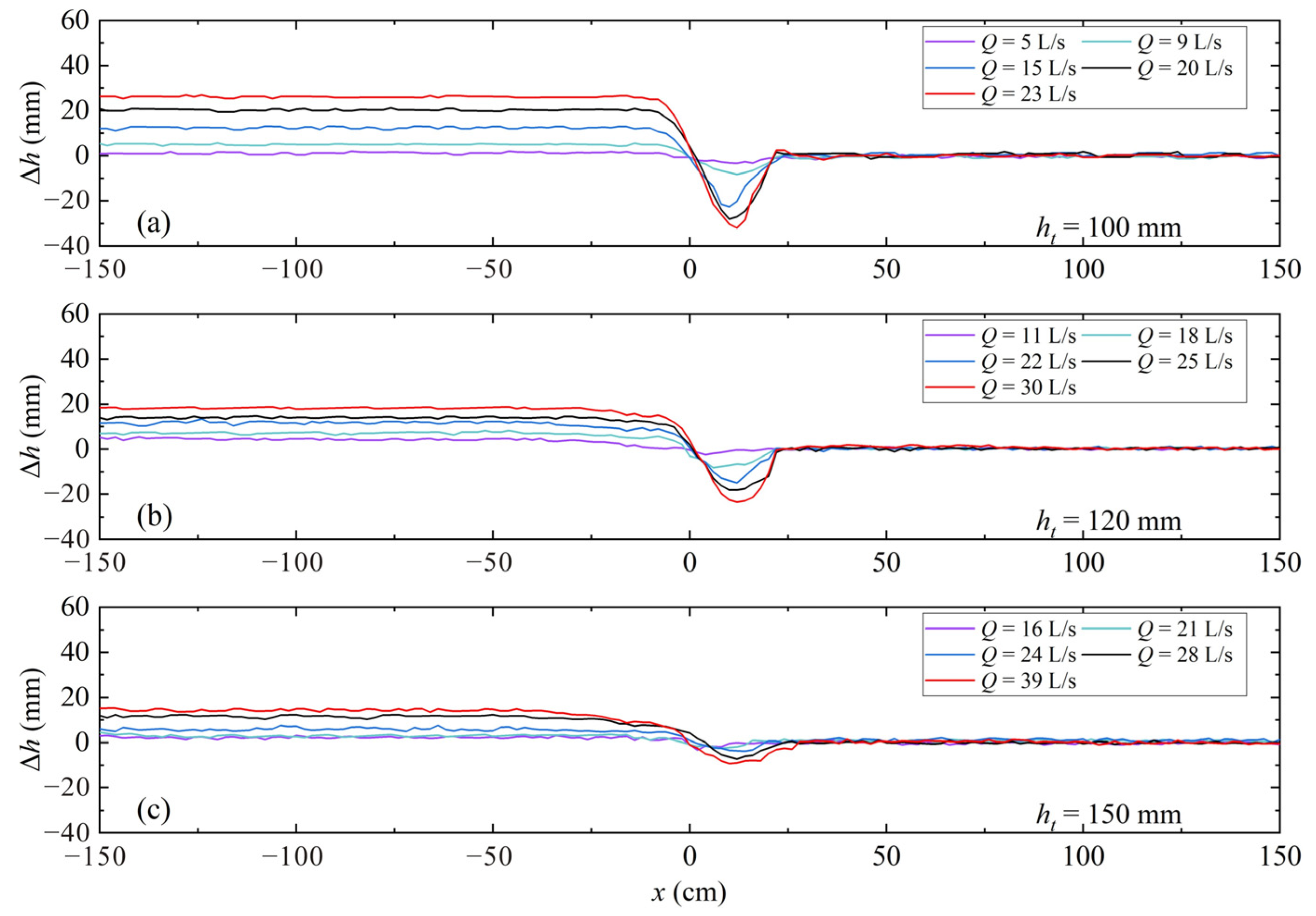
3.1. Effect of Tail-Water Depth on Upstream Water Level Rise

Figure 3 plots the water level rise occurring upstream and downstream of the rock weir (e = 0.21) for different Q and ht values. Δh denotes the differences between the actual and the initial water depth (i.e., ht) along the weir for each test trial. Figure 3 shows that an obvious Δh occurs upstream of the weir (x < 6 cm). Near the weir crest (−6 cm < x < 6 cm), the increased flow velocity decreases the flow potential energy. Subsequently, the water level begins to decrease to connect with the tail-water level (x > 6 cm). Figure 3 summarizes three characteristics for Δh along the submerged weir. (1) The tail-water level is nearly unchanged in this study, indicating that the submerged rock weirs mainly affect the water level upstream of the weir (see each subplot in Figure 3a). (2) With increasing Q, a larger Δh upstream of the weir is expected for each ht (see each subplot in Figure 3a). As the flow inertia is positively related to the flow intensity [3], the increased discharge enhances the weir obstruction on the approaching flow; according to Bernoulli’s continuity equation [30], the velocity of approaching flow reduces greatly, resulting in a significant increase in Δh. (3) The larger the ht, the smaller the Δh upstream of the weir. This phenomenon is found by comparing the maximum Δh value for different ht values in Figure 3. For example, the maximum Δh value in Figure 3c is smaller than that in Figure 3a, although the corresponding discharge is larger in Figure 3c, which suggests that the effect of rock weirs on raising the upstream water level decreases with increasing ht.

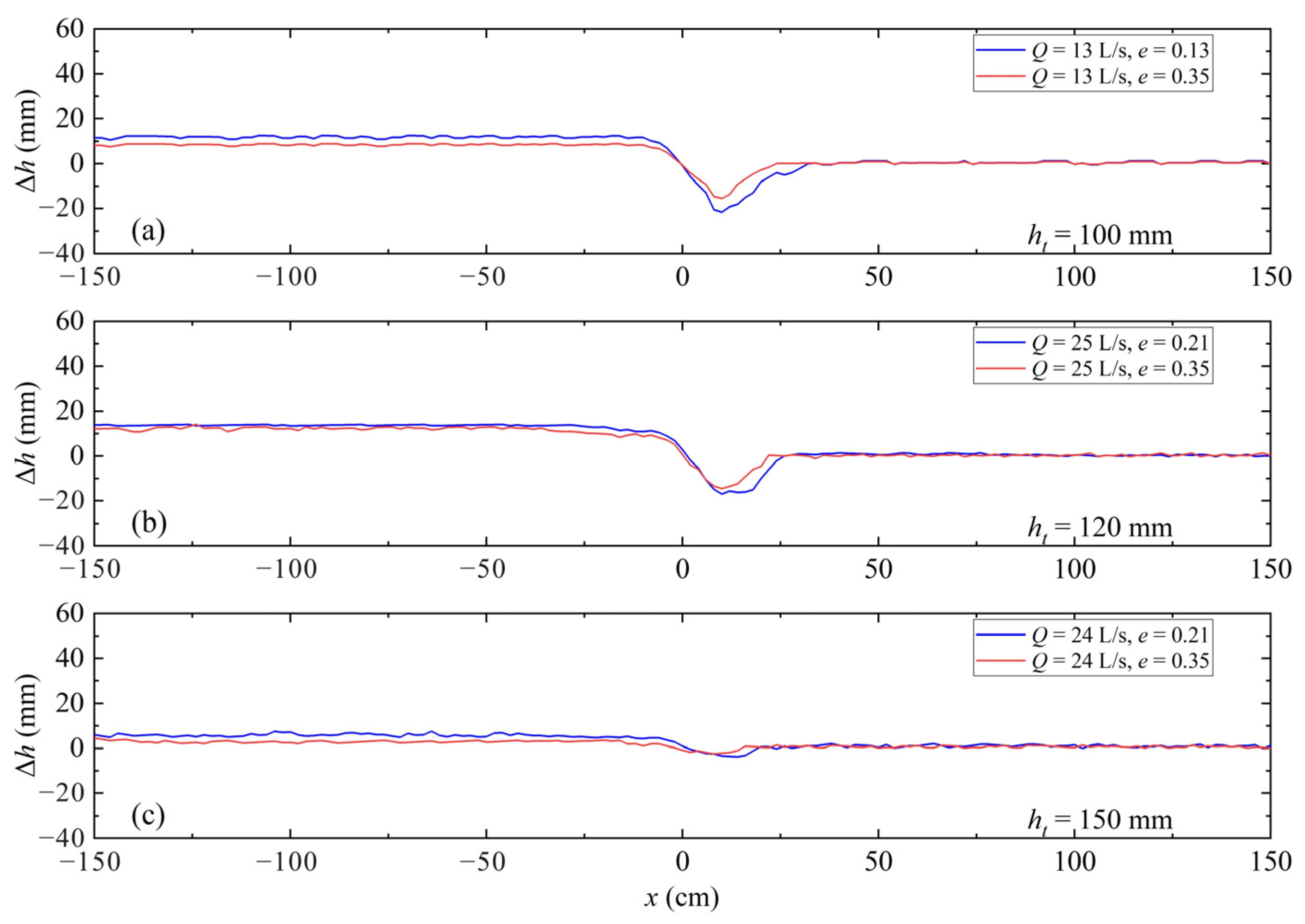
3.2. Effect of Weir Void Ratio on Upstream Water Level Rise

Figure 4 shows the water level rise occurring upstream and downstream of the rock weir for different e and ht values. In each subplot, the discharge Q is fixed. Figure 4 shows that the submerged rock weirs with different e remain only affecting the upstream water level. Namely, the tail-water level is insensitive to the change in e. Furthermore, for the same Q, with larger e, a smaller upstream Δh is expected. This phenomenon is related to the characteristics of the flow passing the weir. Compared with a solid weir, the flow passing a rock weir consists of two components, namely, the flow over the weir (weir overflow) and the flow through the weir (interstitial flow) [21]. Since the increase in e can lead to more flow through the weir, the weir overflow and the corresponding upstream Δh are reduced. This finding agrees well with that in Mohamed [25] based on gabion weirs.

3.3. Estimation of Upstream Water Level Rise

Based on Equation (3), Figure 5 shows the sensitivity of the dimensionless upstream water level rise (i.e., Hd/z) to Ut/g0.5ht0.5, ht/z, and e. Figure 5a–c indicate that for a given e and ht/z, Hd/z increases with increasing Ut/g0.5ht0.5. The increased Froude number raises the kinetic energy of the flowing water, resulting in a more pronounced conversion of kinetic energy to potential energy as the water approaches the weir, thereby raising the water level. Figure 5d–f suggest that for a given e and Ut/g0.5ht0.5, Hd/z decreases with increasing ht/z. This is because with increasing submergence, a decrease in weir obstruction on the approaching flow is expected, allowing the flows to pass the weir more easily and reducing upstream water level rise accordingly. Figure 5g–i indicate that for a given ht/z and Ut/g0.5ht0.5, Hd/z decreases with increasing e. As mentioned in Section 3.2, an increase in e leads to more flow passing through the weir, reducing the weir obstruction on the approaching flow to decrease the upstream water level rise.
Based on the above analysis and Equation (3), Equation (4) is proposed for predicting the water level rise upstream of I-shaped submerged rock weirs using all data in this study (in each test trial, the h0 value used for calculating Hd is the mean value of h0 measured from −1.5 m < x < −0.5 m):
Hd/z = 2.992·(Ut/g0.5ht0.5)1.915·(e)−0.229·(ht/z)−0.939
Equation (4) has a multiple correlation R2 = 0.97. Figure 6 compares the normalized upstream water level rise Hd/z predicted using Equation (4) with the measured values, and shows good agreement with a Mean Relative Deviation (MRD [31] = 0.12). In this study, the MRD is calculated as:
MRD   = 1 n i = 1 n x i y i y i
where n = the number of data points; xi = the predicted value of the i-th data point; and yi = the measured value of the i-th data point.
The estimated water level rise using Equation (4) may also be used for determining the head–discharge relationship of I-shaped rock weirs under submerged conditions. In previous studies, the Poleni formula (Equation (6)) was widely used for calculating the head–discharge relationship of rock weirs after the discharge coefficient is determined [21]:
Q = 2 3 C d B 2 g H 1.5
where Cd = the dimensionless discharge coefficient, and H = the head of water above the weir crest. Since the term H relates to the water level rise upstream of submerged weirs (i.e., H = Hd + htz), Equation (4) may be used for calibrating the discharge coefficient Cd in Equation (5) when the terms Q and B are known. Then, the head–discharge relationship of I-shaped rock weirs under submerged conditions can be determined, which facilitates the design of river training practices.
It should be noted that, as this study is based on flume experiments and can be inevitably affected by scale effects, and Equation (4) is valid for 2 < ht/z < 3, 0.13 < e < 0.35, and 0.10 < Ut/g0.5ht0.5 < 0.47, more field measurements or experimental data using flumes at different scales are required to examine the reliability and practicability of the findings and predictors of this study.

4. Conclusions

Flume experiments were conducted to study the upstream water level rise of submerged rock weirs. The main findings are as follows.
The recorded water level along the flume showed that under submerged conditions, the rock weirs primarily raise the upstream water level, while exerting minimal influence on changing the tail-water level. For a given tail-water depth and void ratio of rock weirs, the upstream water level rise increases with increasing discharge. However, this response becomes insignificant as tail-water depth increases. Furthermore, as the weir void ratio increases, the water level rise upstream of the weir is expected to decrease for a given discharge and tail-water depth.
Based on the experimental data and observations, a predictor including the effects of the Froude number before building the weir, weir submergence, and the weir void ratio was proposed for estimating the water level rise upstream of I-shaped rock weirs under submerged conductions. The computed water level rise agreed well with the measured data. The estimated upstream water level rise may also be useful for determining the head–discharge relationships of submerged rock weirs, which can assist in the design of rock weirs for river engineering.

Author Contributions

Conceptualization, W.Z.; methodology, W.Z. and B.G.; supervision, X.L.; formal analysis, W.Z.; visualization, W.Z.; data curation, W.Z.; funding acquisition, W.Z. and B.G.; writing—original draft preparation, W.Z.; writing—review and editing, W.Z., B.G. and X.L. All authors have read and agreed to the published version of the manuscript.

Funding

This research was funded by the National Key R&D Program of China (2023YFC3208800), the National Natural Science Foundation of China (52309078), the Chongqing Natural Science Foundation Postdoctoral Science Fund (CSTB2023NSCQ-BHX0201), the Science and Technology Research Program of Chongqing Municipal Education Commission (KJQN202300727), the Open Fund of Key Laboratory of Hydraulic and Waterway Engineering of the Ministry of Education, Chongqing Jiaotong University (SLK2023B12), and the Open Fund of State Key Laboratory of Hydraulics and Mountain River Engineering (SKHL2320).

Data Availability Statement

Data related to this study are available from the authors upon reasonable request.

Acknowledgments

The first author would like to thank Shengxian Xu for assisting in analyzing part of results of this study.

Conflicts of Interest

The authors declare no conflicts of interest.

References

  1. USBR (United States Bureau of Reclamation). Rock Weir Design Guidance; USBR Technical Service Center, Sedimentation and River Hydraulics Group: Denver, CO, USA, 2016.
  2. Nichols, M.H.; Polyakov, V.O. The impacts of porous rock check dams on a semiarid alluvial fan. Sci. Total Environ. 2019, 664, 576–582. [Google Scholar] [CrossRef]
  3. Chen, Z.C.; Shao, X.J.; Zhang, J.W. Experimental study on the upstream water level rise and downstream scour length of a submerged dam. J. Hydraul. Res. 2005, 43, 703–709. [Google Scholar] [CrossRef]
  4. Martens, K.D.; Connolly, P.J. Effectiveness of a redesigned water diversion using rock vortex weirs to enhance longitudinal connectivity for small salmonids. N. Am. J. Fish Manage. 2010, 30, 1544–1552. [Google Scholar] [CrossRef]
  5. Baki, A.B.M.; Zhu, D.Z.; Harwood, A.; Lewis, A.; Healey, K. Hydraulic design aspects of rock-weir fishways with notch for habitat connectivity. J. Ecohydraulics 2019, 5, 94–109. [Google Scholar] [CrossRef]
  6. Gordon, R.P.; Lautz, L.K.; Daniluk, T.L. Spatial patterns of hyporheic exchange and biogeochemical cycling around cross-vane restoration structures: Implications for stream restoration design. Water Resour. Res. 2013, 49, 2040–2055. [Google Scholar] [CrossRef]
  7. Radspinner, R.R.; Diplas, P.; Lightbody, A.F.; Sotiropoulos, F. River training and ecological enhancement potential using in-stream structures. J. Hydraul. Eng. 2010, 136, 967–980. [Google Scholar] [CrossRef]
  8. Wang, C.L.; Zhao, Y.; Ning, B.; Bi, J. Permeability evolution of coal subjected to triaxial compression based on in-situ nuclear magnetic resonance. Int. J. Rock Mech. Min. 2022, 159, 105213. [Google Scholar]
  9. Wang, C.L.; Pan, L.H.; Zhao, Y.; Zhang, Y.F.; Shen, W.K. Analysis of the pressure-pulse propagation in rock: A new approach to simultaneously determine permeability, porosity, and adsorption capacity. Rock Mech. Rock Eng. 2019, 52, 4301–4317. [Google Scholar] [CrossRef]
  10. Pasternack, G.B.; Ellis, C.R.; Marr, J.D. Jet and hydraulic jump near-bed stresses below a horseshoe waterfall. Water Resour. Res. 2007, 43, W07449. [Google Scholar] [CrossRef]
  11. Wyrick, J.R.; Pasternack, G.B. Modeling energy dissipation and hydraulic jump regime responses to channel nonuniformity at river steps. J. Geophys. Res. 2008, 113, F03003. [Google Scholar] [CrossRef]
  12. Horton, R.E. Weir Experiments, Coefficients and Formulas; USGS (United States Geological Survey): Washington, DC, USA, 1907.
  13. Ramamurthy, A.S.; Tim, U.S.; Rao, M.V.J. Characteristics of square-edged and round-nosed broad-crested weirs. J. Irrig. Drain. Eng. 1988, 114, 61–73. [Google Scholar] [CrossRef]
  14. Dust, D.; Wohl, E. Characterization of the hydraulics at natural step crests in step-pool streams via weir flow concepts. Water Resour. Res. 2012, 48, 1–14. [Google Scholar] [CrossRef]
  15. FAO/DVWK (Food and Agriculture Organization of the United Nations with Deutscher Verband fur Wasserwirtschaft und Kulturbau). Fish Passes: Design, Dimensions, and Monitoring; DVWK: Rome, Italy, 2002. [Google Scholar]
  16. Holmquist-Johnson, C.L. Numerical Analysis of River Spanning Rock U-Weirs: Evaluating Effects of Structure Geometry on Local Hydraulics. Ph.D. Thesis, Colorado State University, Fort Collins, CO, USA, 2011. [Google Scholar]
  17. Thornton, C.I.; Meneghetti, A.M.; Collins, K.; Abt, S.R.; Scurlock, S.M. Stage-discharge relationships for U-, A-, and W-weirs in un-submerged flow conditions. J. Am. Water Resour. Assoc. 2011, 47, 169–178. [Google Scholar] [CrossRef]
  18. Meneghetti, A.M. Stage-Discharge Relationships for U-, W-, and A-Weirs in Unsubmerged Conditions. Ph.D. Thesis, Colorado State University, Fort Collins, CO, USA, 2009. [Google Scholar]
  19. Baki, A.B.M.; Zhu, D.Z.; Harwood, A.; Lewis, A.; Healey, K. Rock-weir fishway. I: Flow regimes and hydraulic characteristics. J. Ecohydraul. 2017, 2, 122–141. [Google Scholar] [CrossRef]
  20. Kupferschmidt, C.; Zhu, D.Z. Physical modelling of pool and weir fishways with rock weirs. River Res. Appl. 2017, 33, 1130–1142. [Google Scholar] [CrossRef]
  21. Zeng, Y.X.; Ismail, H.; Liu, X.F. Flow decomposition method based on computational fluid dynamics for rock weir head-discharge relationship. J. Irrig. Drain. E. 2021, 147, 04021030. [Google Scholar] [CrossRef]
  22. Pagliara, S.; Palermo, M.; Kurdistania, S.M.; Hassanabadi, L.S. Erosive and hydrodynamic processes downstream of low-head control structures. J. Appl. Water. Eng. Res. 2015, 3, 122–131. [Google Scholar] [CrossRef]
  23. Zhang, W.; Nie, R.H.; Melville, B.W.; Whittaker, C.N.; Shamseldin, A.Y.; Liu, X.N.; Wang, L. Failure of rock weirs due to rock dislodgements. J. Hydraul. Res. 2023, 61, 356–368. [Google Scholar] [CrossRef]
  24. Pagliara, S.; Palermo, M. Rock grade control structures and stepped gabion weirs: Scour analysis and flow features. Acta. Geophys. 2013, 61, 126–150. [Google Scholar] [CrossRef]
  25. Mohamed, H.I. Flow over gabion weir. J. Irrig. Drain. E. 2010, 136, 573–577. [Google Scholar] [CrossRef]
  26. Bell, F.G. Engineering Properties of Soils and Rocks, 3rd ed.; Butterworth-Heinemann: Oxford, Boston, 1992. [Google Scholar]
  27. Zhao, Y.; Liu, H.H. An elastic stress-strain relationship for porous rock under anisotropic stress conditions. Rock Mech. Rock Eng. 2012, 45, 389–399. [Google Scholar] [CrossRef]
  28. Zhang, W.; Wang, L.; Melville, B.W.; Guan, D.W.; Whittaker, C.N.; Shamseldin, A.Y. Characteristics of the flow field within a developing scour hole at a submerged weir. J. Hydraul. Res. 2021, 60, 283–294. [Google Scholar] [CrossRef]
  29. Ettema, R.; AuBuchon, J.; Holste, N.; Varyu, D.; Baird, D.; Padilla, R.; Posner, A.; Thornton, C. Large flume tests on flow dislodgment of rocks forming bendway weirs. J. Hydraul. Eng. 2020, 146, 04020008. [Google Scholar] [CrossRef]
  30. Shatalov, A.; Hafez, M. Numerical solutions of incompressible Navier–Stokes equations using modified Bernoulli’s law. Int. J. Numer. Meth. Fl. 2003, 43, 1107–1137. [Google Scholar] [CrossRef]
  31. Guan, D.W.; Melville, B.W.; Friedrich, H. Live-bed scour at submerged weirs. J. Hydraul. Eng. 2015, 141, 04014071. [Google Scholar] [CrossRef]
Figure 1. Illustration of experimental flume and measurement devices.
Water 16 02136 g001
Figure 2. Definition of main test nomenclatures and the coordinate system (x-O-y) for measurement.
Water 16 02136 g002
Figure 3. Water level rise along the submerged rock weirs for various ht values at e = 0.21: (a) ht = 100 mm; (b) ht = 120 mm; and (c) ht = 150 mm.
Water 16 02136 g003
Figure 4. Water level rise along the submerged rock weirs for various e values: (a) ht = 100 mm; (b) ht = 120 mm; and (c) ht = 150 mm.
Water 16 02136 g004
Figure 5. Sensitivity of Hd/z to Ut/g0.5ht0.5 (ac), ht/z (df), and e (gi).
Water 16 02136 g005
Figure 6. Comparison of measured and calculated Hd/z.
Water 16 02136 g006
Table 1. Summary of the experimental conditions.
Q (L/s)z (mm)D (mm)eht (mm)Hd (mm)h0 (mm)Fu
9~1850120.131005~15105~1150.17~0.29
11~2150120.131204~11124~1310.16~0.29
18~2650120.131502~6152~1560.19~0.27
5~2350240.211001~26101~1260.11~0.33
11~3050240.211203~18123~1380.17~0.37
16~3950240.211501~14151~1640.19~0.40
9~2350330.351003~27103~1270.17~0.33
14~2950330.351203~21123~1410.20~0.35
24~3950330.351504~15154~1650.25~0.37
Notes: Fu is the Froude number of the approach flow, Fu = U0/(gh0)0.5.
Disclaimer/Publisher’s Note: The statements, opinions and data contained in all publications are solely those of the individual author(s) and contributor(s) and not of MDPI and/or the editor(s). MDPI and/or the editor(s) disclaim responsibility for any injury to people or property resulting from any ideas, methods, instructions or products referred to in the content.

