Abstract
This study investigates the role of emerged vegetation in enhancing the performance of submerged spur dikes for better flow control and bank protection in river systems. The research utilizes a numerical model based on Computational Fluid Dynamics (CFD), validated with experimental data. After validation, the study explores various configurations of vegetated spur dike, adjusting the submergence heights of the impermeable spur dike to achieve porosity ranging from fully impermeable to highly porous. Porosity levels of 24%, 48%, and 72% were chosen based on the spur dike height and the effectiveness of staggered vegetation arrangements in maximizing drag and reducing velocity. This approach aims to determine their impact on flow structure, velocity, and turbulence characteristics. The results reveal that impermeable dikes create strong recirculation zones downstream, increasing the potential for bank erosion. Introducing vegetation on the dike, particularly at moderate porosities (24% and 48%), effectively disrupts this behavior by reducing downstream velocity and mitigating mass and momentum exchange concentration between the spur dike field and the mainstream. However, the highest porosity case (72%) offered reduced flow resistance, limiting its protective effectiveness. Analysis of velocity and stress distributions showed that vegetation porosity significantly impacts normal and shear stresses, influencing flow stability at critical points around the spur dike. The findings signify the potential of integrating vegetation into spur dike designs to achieve a balance between effective flow conveyance and erosion control even in the spur dike submergence condition. This approach can outperform conventional emerged impermeable spur dikes, as supported by previous studies that demonstrate the effectiveness of porous and vegetated structures in reducing flow resistance, minimizing stagnation zones, and improving sediment deposition compared to impermeable designs.
1. Introduction
Rivers are integral to the natural environment, shaping landscapes, supporting ecosystems, and providing essential resources for human development. Their dynamic flow patterns and sediment transport processes are vital for maintaining ecological balance and ensuring the sustainability of surrounding habitats. However, inadequate river management can lead to significant social, environmental, and economic consequences, including community displacement due to flooding (social), loss of biodiversity and habitat destruction (environmental), and substantial financial losses from damage to infrastructure and agricultural lands (economic) [1]. Effective management of river systems is therefore crucial to mitigate these challenges and maintain their multifaceted functionality.
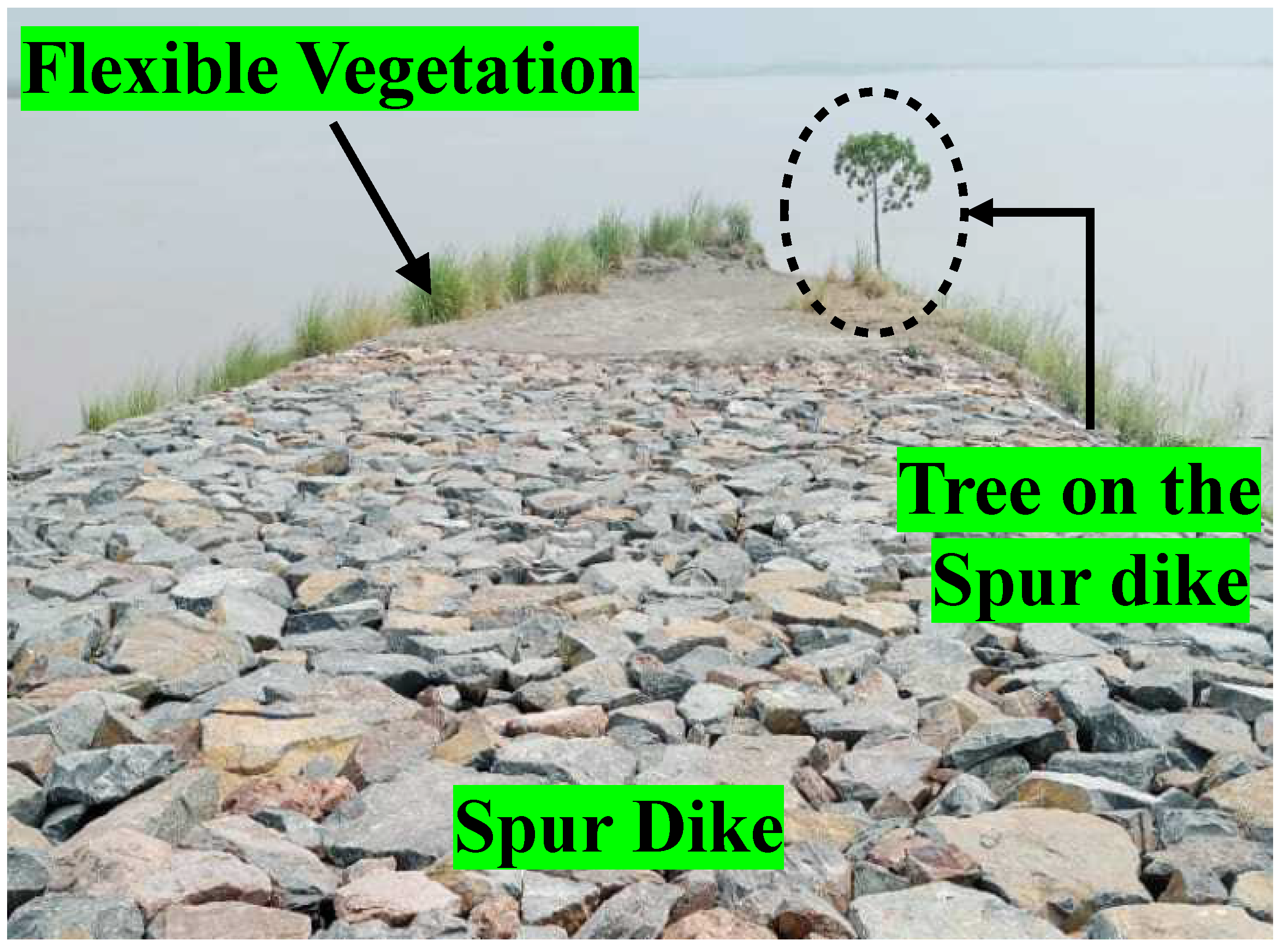
To address these issues, hydraulic engineering solutions, particularly river training structures, have been extensively employed. Spur dikes, for example, are commonly used structures that extend from riverbanks into the water to alter flow patterns, control sediment transport, and protect banks from erosion [2,3]. By modifying the velocity and turbulence of river flows, spur dikes create localized flow conditions that can stabilize channels and improve riverbank integrity. These structures have proven effective in numerous river management applications, but their design and implementation often require optimization to balance hydraulic efficiency and environmental impacts. Spur dikes typically feature a core made of earth, consisting of granular and sometimes various soil types, depending upon the locally available materials [4]. New spur dikes do not have vegetation and feature a stone surface. Over time, as the spur dikes mature, the amount of vegetation covering them tends to increase [5,6]. The authors have observed the similar behavior of vegetated spur dike after a field visit to Punjab, Pakistan, as illustrated in Figure 1.
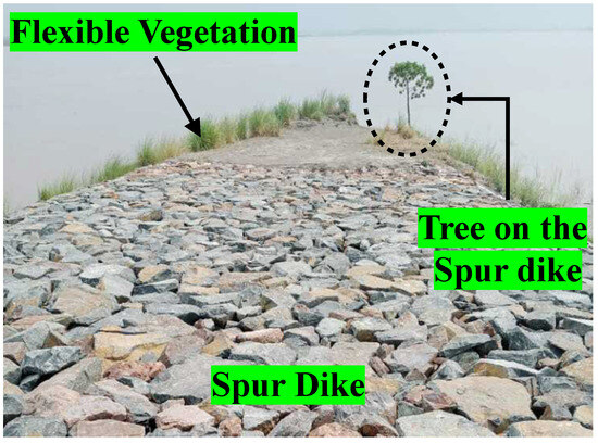
Figure 1.
Naturally grown trees and vegetation on the top of the spur dike in Punjab, Pakistan.
Impermeable or conventional spur dikes are prepared to function optimally under a medium depth of water levels, while the crests stay emerged. In these scenarios, the main channel carries the bulk of the water flow with the lowest interchange between the channel and the spur dike field [7]. In the vicinity of spur dikes there is a significant increase in the velocity of water flow, and downstream vortices are often seen [8,9], which divides the flow into three zones, named the spur dike field, the momentum exchange zone, and the mainstream zone as shown in Figure 2a. The momentum exchange zone refers to the region where energy is transferred between the main flow and the wake, playing a crucial role in reducing flow velocity, generating turbulence, and influencing sediment transport. When the depth of water increases more than the spur dike height, the spur dikes are to be considered submerged. Even though the highest flow velocities are sustained in the main channel, the submerged spur dikes behave as obstacles that slow down the flow in those parts of the open channel [5,10,11]. This impact is especially pronounced during flood events. The submerged status of the spur dikes also introduces ambiguities regarding their effectiveness. Submerged spur dikes, such as the stream barbs implemented in North America, are used for environmental restoration in channelized rivers, where they reduce flow velocity and enhance sediment deposition for habitat improvement. In contrast, emerged spur dikes are conventional structures used globally for riverbank protection and navigational purposes as they effectively deflect flow toward the mainstream side to stabilize banks and maintain navigation channels. In conducting hydraulic assessments for natural riverbeds, it is vital to consider the influence of vegetation within the riverbed, around the banks, and also available at the floodplains. The flow dynamics of vegetation are significantly affected by a mix of the stream’s hydrodynamic characteristics and the specific traits of the vegetation, including density, biomechanical properties, and geometric characteristics [12]. A staggered arrangement of piles impacts flow dynamics more positively than an inline arrangement, particularly in terms of reducing velocity near the banks [13]. The drag force in a staggered vegetation arrangement, also known as the ’colony type’, is greater than that in a ’grid’ arrangement [14].
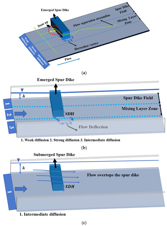
Figure 2.
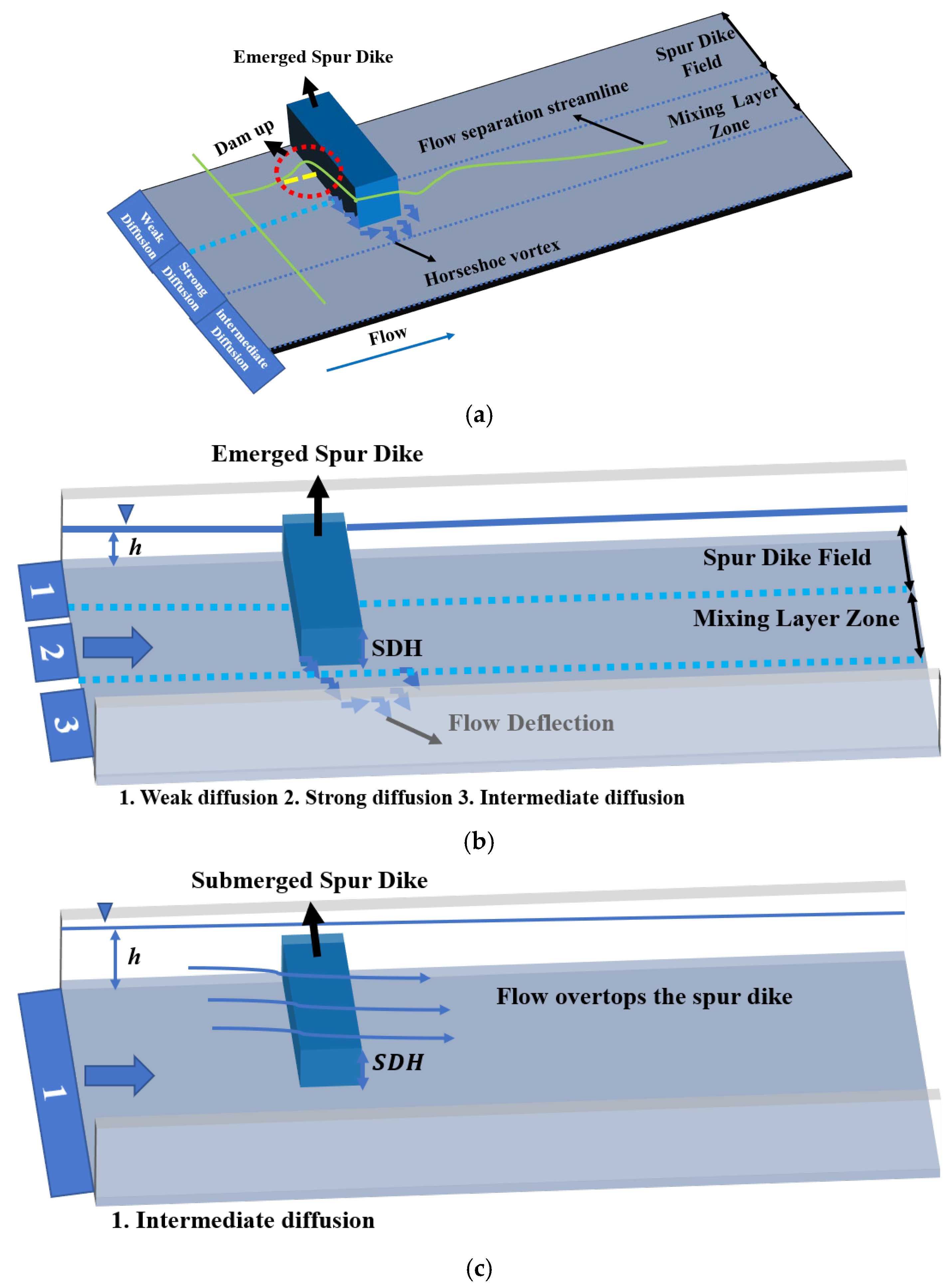
Flow characteristics around a single emerged and submerged impermeable spur dike. (a) Three-dimensional schematic of the flow structure around an emerged spur dike, showing flow separation, dam-up effect, mixing layer zone, and the formation of the horseshoe vortex. (b) Top view of the flow field around an emerged spur dike, highlighting flow deflection, spur dike height (SDH), diffusion regions (weak, strong, and intermediate), and the mixing layer zone. (c) Top view of the flow field around a submerged spur dike, illustrating overtopping flow and intermediate diffusion zone.
Advancements in understanding vegetated spur dikes and their impacts on flow and structural dynamics have been facilitated by a combination of experimental and numerical approaches [2,12]. Research focusing on the development of turbulent flow structures near vegetated spur dikes has been extensively pursued [6,15,16]. Researchers employed Particle Image Velocimetry (PIV) to capture and analyze turbulent flow patterns within open-channel environments. A key component of these studies was the comparative analysis between impermeable and vegetated spur dikes, especially concerning differences in permeability. The permeability of a spur dike was found to significantly influence the position of the maximum Reynolds stress downstream of the structure. A reduced permeability was associated with a higher crest height, which corresponded to an increase in the peak stress value [3]. Additionally, Sukhodolov et al. [17] carried out field investigations to examine the impacts of both riparian and aquatic vegetation on hydrodynamic processes within spur dike fields. Their experiments utilized large-scale spur dike models incorporating both rigid and flexible artificial vegetation in natural river environments. The findings indicated that vegetation subtly alters the hydrodynamic interactions between the main river channel and the spur dike field [18].
Some researchers have highlighted the influence of riverine vegetation on flow velocity and turbulence [19,20,21,22], but limited research has examined the specific flow dynamics of vegetated spur dikes under submerged conditions, particularly under high flood events. During high flood events, the effectiveness of spur dikes as flow deflectors and riverbank protectors significantly diminishes once they become submerged. Traditional impermeable spur dikes, effective under lower water stages, fail to prevent erosion adjacent to the spur dike during overtopping events. This leads to increased pressure on the upstream face of the spur dike, heightening the risk of partial or complete failure. Figure 2a–c visually supports this description. To address this issue, this study explores various configurations of vegetated spur dikes, adjusting their submergence heights to vary their porosity from fully impermeable to highly porous. Unlike conventional research that primarily focuses on impermeable spur dikes, this study introduces vegetated and porous configurations to enhance hydraulic performance, minimize turbulence, and control erosion more effectively. This innovative approach aims to provide sustainable solutions for river engineering, combining ecological and structural benefits. The findings aim to provide practical insights for designing more resilient and sustainable spur dikes that effectively balance flow control with erosion mitigation, even under challenging flood conditions.
2. Methodology
2.1. Experimental Setup
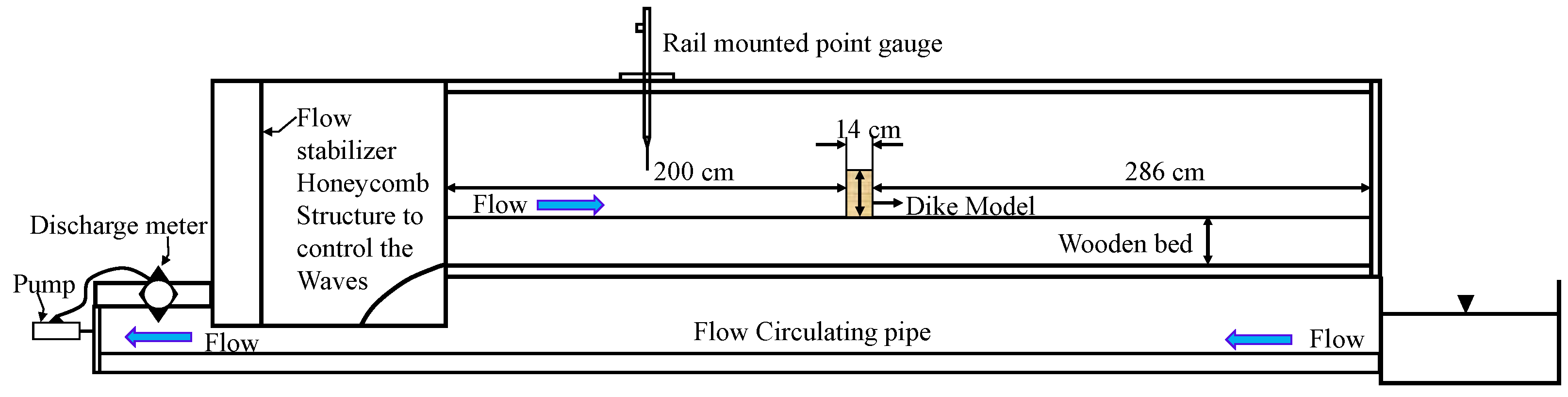
In this study, we adopted the experimental framework presented by Iqbal and Tanaka [23] to validate our CFD computation model. Their experimental arrangement involved using a glass-sided flume with dimensions of 5 m in length, 0.7 m in width, and 0.5 m in depth, located at Saitama University in Japan. A depiction of their experimental layout can be found in Figure 3. A single impermeable spur dike, measuring 17.5 cm in length and 14 cm in width, was positioned in an emerged state within the experimental channel. Previously, many researchers utilized rectangular open channels with glass sides [2,5,12,16].
The experimental design aimed to replicate general ground conditions instead of specific geographical features. Large floods, particularly in inland or mountainous regions, typically last for extended periods, making it difficult to reproduce such events accurately in laboratory conditions. To address this challenge, a controlled pump discharge () was utilized to simulate flood flows within the flume. By assuming quasi-steady behavior typical of prolonged flood events, the experiments used steady-state flow conditions to represent large-scale flood scenarios. By assuming quasi-steady behavior typical of prolonged flood events, where flow characteristics such as velocity and depth change gradually over time, the experiments used steady-state flow conditions to represent large-scale flood scenarios. This approach is computationally efficient and aligns with previous studies that have successfully modeled similar flood scenarios using quasi-steady assumptions [1,12,23].
The scaling in the experiments was implemented at a 1/15 scale. Flow parameters were derived using Froude number similarity, which is a standard approach for maintaining dynamic similarity in fluid mechanics. Historical Froude number data for the Jinnah and Taunsa Barrages on the Indus River, collected over 59 years by the Punjab Irrigation Department, Pakistan, provided the basis for selecting the experimental range. The chosen initial Froude number for the subcritical flow regime was approximately 0.59, calculated using where the obstruction-free water depth was 8 cm.
We applied this experimental methodology to validate and assess the accuracy of our computational model.
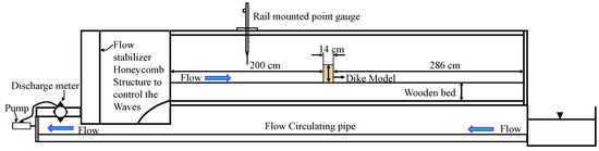
Figure 3.
Diagrammatic representation of the experimental arrangement by Iqbal and Tanaka [23].
Figure 3.
Diagrammatic representation of the experimental arrangement by Iqbal and Tanaka [23].
2.2. Numerical Modeling
2.2.1. Governing Equations
The continuity and Reynolds-averaged Navier–Stokes (RANS) equations formed the basis for the numerical modeling of steady, incompressible flow within an open channel environment. These equations are formulated as follows:
1. Continuity Equation:
where U, V, and W are the velocity components in the U, V, and W direction, respectively. X, Y, and Z are the spatial coordinates.
2. Momentum Equation
where and are the time-averaged velocity components in and directions, respectively. P is the pressure, and are the fluid density and kinematic viscosity, and represents the time-averaged product of the fluctuating velocity components, which is the Reynolds stress tensor [24].
Equation (2) represents the Reynolds-Averaged Navier–Stokes (RANS) momentum equation, which is derived by time-averaging the Navier–Stokes momentum equation for incompressible flow. Starting from the momentum conservation equation for the X-direction in 3D, incompressible flow is given by:
where , V, and W are the velocity components in the X, Y, and Z directions, respectively; is the local acceleration term, is pressure gradient, and is the viscous diffusion term. For steady (time-independent) and incompressible flow, the local acceleration term () is removed, and the continuity equation ensures mass conservation as given in Equation 1. To account for turbulence, the velocity, the velocity and pressure (P) are decomposed into mean (, , ) and fluctuating () components:
Substituting these into the Navier–Stokes equations and time-averaging removes the fluctuating terms’ time derivatives, yielding the RANS momentum Equation (2):
3. Reynolds Stress Transport Equation
The transport equation for Reynolds stresses is as follows:
where represents the rate of change of Reynolds stresses, refers to the convection transport, signifies the production rate of Reynolds stresses, is the diffusion-related stress transport, denotes the dissipation rate of stresses, is the stress transport due to turbulent pressure-strain interactions, and describes the rotational effects, with as the rotational vector and as the permutation tensor. The constants used in the model are and .
4. Turbulent Kinetic Energy (TKE)
The TKE is defined as
5. Dissipation Rate:
The dissipation rate is modeled as:
2.2.2. Modeling Setup
In adapting the experimental setup described by Iqbal and Tanaka [23] for computational analysis, the computational domain was modified for efficiency and accuracy. The length of the domain was reduced to 160 cm to include a critical feature of a single impermeable dike, while considering the original experimental width of 70 cm and a depth of 8 cm that mirrors the controlled flow depth in the experiments [12]. This reduction was implemented to minimize computational cost following successful validation of the experimental data, a practice commonly adopted in similar studies [5,12]. The reduced domain length did not affect flow interactions or result accuracy, as the experimental velocity data were successfully captured, and a mesh sensitivity analysis was conducted to ensure reliability. Figure 4a illustrates the scaled-down computational domain, highlighting the dimensions including the spur dike length (SDL), spur dike width (SDW), spur dike height (SDH), and placement of the spur dike within the model. To determine the optimal mesh configuration for accurate and computationally efficient simulations, a mesh independence study was performed with three mesh densities: 0.25 million cells (coarse), 1.1 million cells (medium), and 1.8 million cells (fine). The assessment revealed velocity differences of approximately 5% between the coarse and medium meshes. The mesh independence trial result is shown in Figure 4b. Consequently, the medium mesh with 1.1 million cells was selected due to its suitable balance of accuracy and computational demand. Moreover, Figure 4c presents the meshing of the computational domain in the presence of a single impermeable spur dike for case NV.
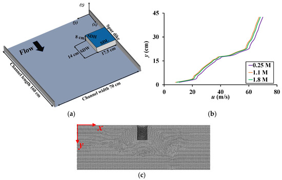
Figure 4.
The computational domain of the CFD model contains the detailed (a) schematic diagram, (b) results of depth-averaged streamwise velocity profiles at position P1 for the mesh independence trial, and (c) meshing of a single impermeable spur dike.
The simulation’s boundary conditions were meticulously chosen to replicate the experimental setup as closely as possible, considering the reduced size of the computational domain. The pressure–velocity coupling was modeled using the semi-implicit method for pressure-linked equations consistent (SIMPLEC) algorithm, with pressure discretization performed using the “body force weighted” method. The turbulent kinetic energy, turbulent dissipation rate, and momentum were discretized using “first-order upwind” schemes to ensure solution convergence, with a convergence criterion for all residuals set at 1 × 10⁻⁶. At the inlet, a mass flow rate condition was applied to accurately simulate the flow dynamics as per the experimental setup, while an outlet boundary condition at the domain’s exit allowed the flow to leave freely, avoiding any backpressure effects. Non-slip conditions were assigned to the boundary walls, the spur dike, and the channel bed to capture the interaction between the fluid and the solid surfaces. Non-slip conditions are critical in fluid dynamics simulations as they ensure that the velocity of the fluid at the solid boundaries (e.g., walls, channel bed, and spur dike) matches the velocity of the boundary surface itself, which is typically zero for stationary boundaries. This condition is essential to accurately capture the realistic interactions between the fluid and the solid surfaces, such as shear stresses, flow separation, and turbulence generation, which significantly influence the overall flow behavior and the accuracy of the results.
The top water surface was modeled using a symmetry boundary condition, restricting displacement in the normal direction while allowing tangential sliding. In fixed-bed flume experiments, the slope of the water surface over the emerged spur dike flow is typically constant, so a rigid lid approximation was used to simulate the free surface, assuming it remains unchanged. The flume’s sidewalls and the spur dike structures were treated as solid boundaries to ensure an accurate representation of the physical flow conditions [25].
The Reynolds Stress Model (RSM) turbulence model was applied to provide a detailed resolution of the flow’s turbulent structure. The RSM was chosen because it is particularly effective in capturing complex flow situations involving strong streamline curvature, swirling, and recirculation, providing a detailed resolution of the flow’s turbulent structure. Unlike eddy-viscosity models (e.g., k-ε or k-ω), which assume isotropic turbulence, the RSM directly resolves the individual components of the Reynolds stress tensor, allowing for a more accurate representation of anisotropic turbulence effects. This capability makes the RSM highly suitable for simulating flows with significant directional variations and complex interactions between fluid and solid boundaries. Finally, the CFD simulations were conducted to analyze the intricate fluid dynamics, ensuring the modeled flow characteristics align closely with the experimental observations. This methodological approach not only optimizes computational resource use but also robustly supports the validation of experimental findings.
2.3. Simulation Setup
In this study, the computational domain used for the numerical simulations is illustrated in Figure 4. The study explores various configurations of vegetated spur dikes, adjusting their submergence heights to vary their porosity from fully impermeable to highly permeable. The specific cases are presented in Table 1. The measuring locations in the simulation domain are shown in Figure 5. A total of five measuring locations are selected in the domain, specifically two streamwise positions (SP1 and SP2) and three cross-sectional positions (CP1-CP3). Furthermore, to calculate vertical velocity (w) distribution, two critical positions P1 and P2 are selected. The arrangements of the cases from impermeable to vegetated spur dikes are shown in Figure 6. To simulate the vegetated spur dike, a staggered arrangement of rigid cylinders was chosen. Takemura and Tanaka [26] suggested that a staggered arrangement of vegetation provides a greater drag force compared to grid configurations. This setup aims to realistically model the interactions between flow dynamics and vegetative structures, thereby potentially offering more effective flood mitigation. Additionally, staggered arrangements of multiple vegetated spur dikes can enhance turbulence due to overlapping wakes, significantly influencing sediment transport and deposition patterns. These configurations may also provide improved erosion control by dissipating flow energy over a broader area, making them a promising area for future research.

Table 1.
Simulation cases of the numerical model.
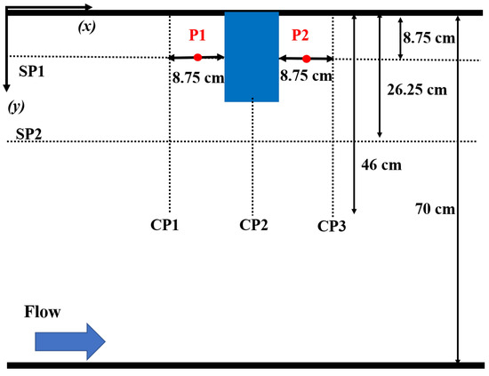
Figure 5.
Measuring location in the computational domain of the CFD model, P1 and P2 represent the vertical measuring locations, CP1, CP2, and CP3 denote the spanwise measuring locations, while SP1 and SP2 indicate the streamwise measuring locations.
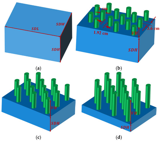
Figure 6.
Characteristics of (a) NV, (b) LV-24, (c) MV-48, and (d) HV-72 spur dike cases.
3. Results and Discussion
3.1. Model Validation
The accuracy of our numerical model is confirmed through a comprehensive comparison with the experimental results documented by Iqbal and Tanaka [23]. The locations of the measuring locations (S1 and S2) used in the experimental setup are depicted in Figure 7a, providing essential context for the validation process. Figure 7b presents a detailed comparison between numerical predictions and the corresponding experimental data at these specific positions. The numerical results (S1 Numerical and S2 Numerical) closely align with the experimental observations (S1 Experimental and S2 Experimental) at both positions (S1 and S2), confirming the model’s accuracy. This alignment highlights the model’s accuracy in capturing and accurately replicating the essential dynamics and variations observed experimentally, affirming its suitability for extended analysis in similar conditions. The accuracy of the computational model is further explained in Table 2.
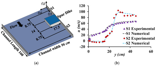
Figure 7.
(a) Streamwise measuring location (S1 and S2) used in the experimental setup, (b) comparison between numerical and experimental results.
Table 2.
Accuracy of computational domain against experimental data at specified locations.
3.2. Velocity Distribution Profiles
3.2.1. Depth-Averaged Streamwise Velocity Distribution
The depth-averaged streamwise velocity (u) was analyzed at three cross-sectional locations (CP1, CP2, and CP3) and two streamwise positions (SP1 and SP2) to understand the flow behavior influenced by varying spur dike porosities. The x-axis and y-axis were non-dimensionalized using the spur dike width (SDW) and initial velocity (U) to standardize the results and facilitate comparisons across configurations as shown in Figure 8. The analysis reveals that spur dike porosity in terms of vegetation significantly affects the velocity distribution near and around the dike, with important implications for hydraulic performance and erosion control.
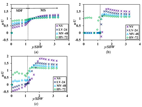
Figure 8.
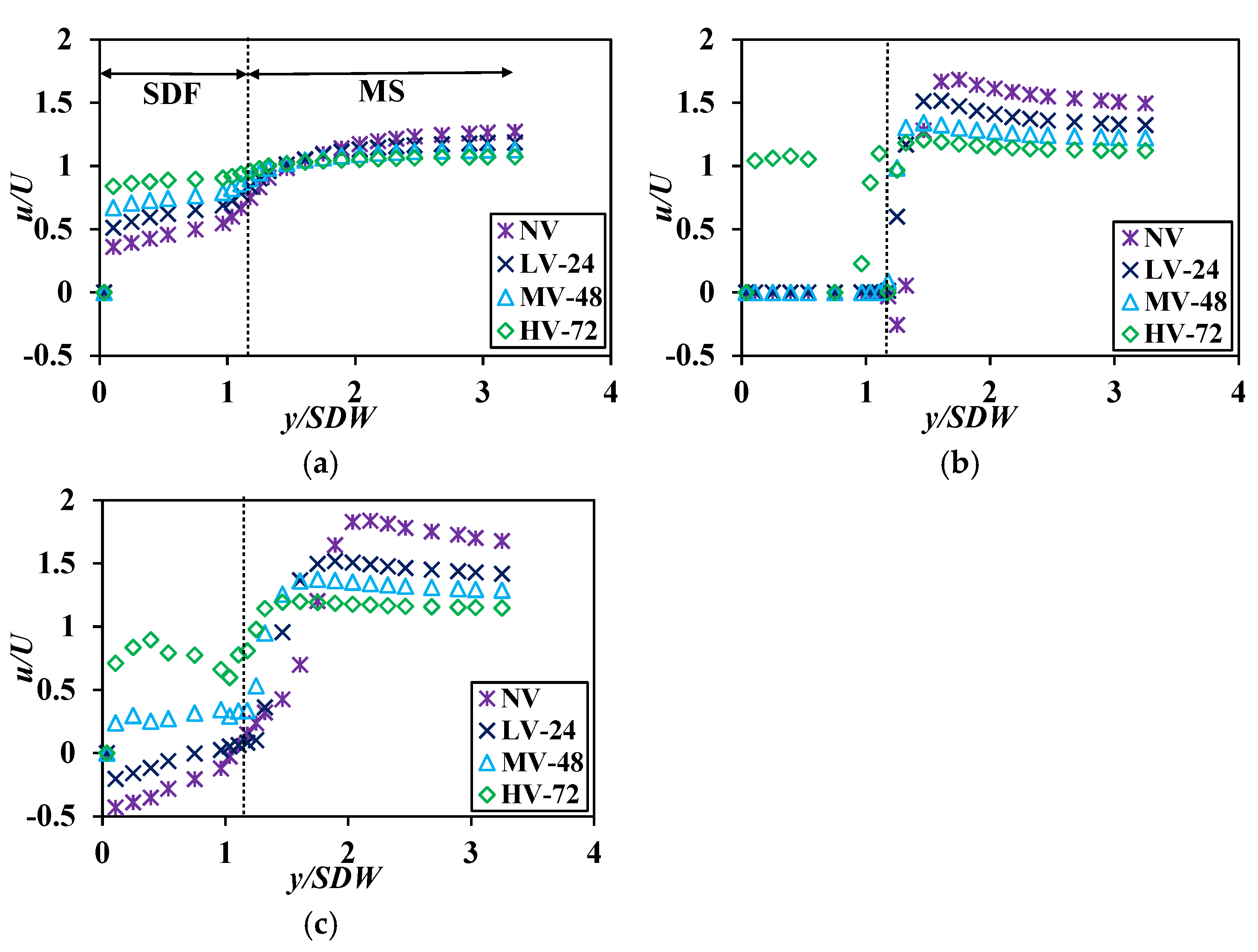
Depth-averaged streamwise velocity distribution in spanwise direction at (a) CP1, (b) CP2, and (c) CP3. SDF and MS represent the spur dike field and the mainstream, respectively.
At CP1, which represents the upstream section, all cases showed a gradual increase in velocity as the flow moved from the mainstream towards the spur dike region. This increase corresponds to the reduction in flow resistance and the acceleration of the flow as it enters the unaffected channel zone. Within the spur dike field (SDF), the impermeable spur dike in NV exhibited the most pronounced velocity reduction, with normalized velocity (u/U) remaining below 0.3 near y/SDW = 1.0. This reflects the concentrated blockage of momentum and the inability of the flow to penetrate the structure. In comparison, porous configurations (LV-24, MV-48, and HV-72) resulted in progressively higher velocities in the SDF, with values reaching approximately 0.5, 0.7, and 0.8, respectively, near y/SDW = 1.0. These represent velocity increases of 67%, 133%, and 167%, respectively, compared to NV.
In the mainstream (MS), velocity profiles showed smoother transitions as porosity increased. For example, at y/SDW = 2.5, the normalized velocity for NV remained approximately 1.1, while LV-24, MV-48, and HV-72 exhibited higher velocities of 1.3, 1.5, and 1.6, representing increases of 18%, 36%, and 45%, respectively, compared to NV. The impermeable spur dike in NV exhibited the most pronounced velocity reduction near the spur dike edge, reflecting the concentrated blockage of momentum and the inability of the flow to penetrate the structure. This stagnation effect aligns with Haider et al. [3], who demonstrated that impermeable spur dikes generate high-pressure zones upstream, significantly altering local flow dynamics. By contrast, the porous configurations in LV-24, MV-48, and HV-72 progressively reduced resistance near the dike, resulting in higher velocities closer to the structure. These findings are consistent with the previous studies [27,28], which highlighted the benefits of porosity in reducing stagnation zones and promoting smoother velocity profiles.
At CP2, located at the midpoint of the spur dike, the NV case again displayed the lowest velocity values, underscoring the impermeable dike’s capacity to generate a concentrated momentum exchange. This momentum exchange refers to the interaction between the flow and the spur dike surface, where the incoming flow is deflected around the spur dike. This deflection creates localized regions of increased shear stress and turbulence, redistributing velocity and affecting both upstream and downstream flow patterns. This process is critical in understanding the hydrodynamic behavior around the spur dike and its influence on the surrounding flow field. This behavior is a direct result of the impermeable dike’s inability to dissipate flow energy effectively, leading to stagnation at the upstream corner and reduced flow near the center of the spur dike field. Similar trends have been documented previously [7,29], where impermeable spur dikes were shown to obstruct flow continuity and create localized low-velocity zones. In contrast, porous configurations in MV-48 and HV-72 cases allowed for enhanced energy dissipation and smoother momentum transfer, thereby exhibiting higher velocity values at CP2. The ability of the high porous vegetation arrangement to facilitate better flow interactions supports findings from many researchers [12,30,31], who observed that higher porosity levels lead to improved hydraulic performance by minimizing sharp velocity gradients and distributing energy more uniformly.
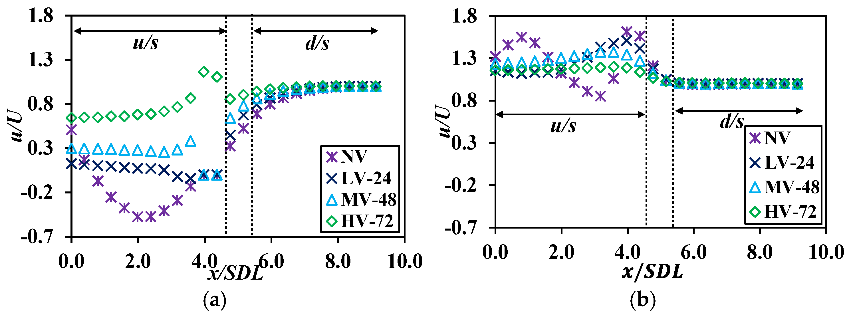
In Figure 8c, NV demonstrated a significant reduction in velocity within the spur dike field, further emphasizing the impermeable spur dike’s inability to effectively manage flow transitions. This sharp velocity drop of 33% near the structure increases the risk of localized erosion and structural instability, particularly under high-flow conditions. Porous spur dike configurations, particularly in MV-48 and HV-72 cases, exhibited higher velocities within the spur dike field, indicating smoother flow transitions and reduced wake effects. These smoother transitions are beneficial in reducing localized erosion near the dike, minimizing sediment transport disruptions, and enhancing the overall stability of the surrounding environment. This highlights the potential of porous configurations for improving flow management and mitigating adverse hydrodynamic impacts. Shiono and Knight [32] reported that porous structures mitigate wake formation and promote more uniform velocity profiles downstream, reducing erosion potential and improving stability. The streamwise analysis provided further insights into the effects of porosity on flow behavior as shown in Figure 9. At SP1 in Figure 9a, the differences in depth-averaged velocity at the downstream side were less pronounced compared to the upstream side. The HV-74 case, characterized by the highest porosity (74%), exhibited higher velocities due to minimal flow resistance. This behavior reflects the reduced drag forces associated with increased porosity, which have been discussed extensively in previous studies [8,23,26]. In contrast, the impermeable configuration in NV resulted in higher resistance, leading to reduced velocities. These results highlight the critical role of porosity in modulating drag forces and optimizing flow conditions in the upstream region. Moreover, vegetated spur dikes allow more flowers and forbs to grow to enhance plant diversity, which in turn benefits insects and other wildlife.

Figure 9.
Depth-averaged streamwise velocity distribution in a streamwise direction at (a) SP1 and (b) SP2. u/s and d/s represent the upstream and downstream, respectively, while dotted lines represent the location of the spur dike.
Figure 9b shows the depth-averaged velocity distribution at SP2. The porous spur dike configurations in MV-48 and HV-72 cases exhibited significant velocity reductions in front of the dike. This behavior indicates effective energy dissipation upstream, a critical factor in mitigating erosion and structural damage. The ability of porous dikes to reduce velocity at the upstream previously emphasized the importance of energy dissipation in ensuring spur dike stability under emerged and submerged conditions [23,33]. The NV case, on the other hand, showed less effective energy dissipation, leading to concentrated flow and higher erosion potential downstream. The maximum velocity gradients observed in impermeable spur dike configuration, also shown in Figure 2a, highlighted the disadvantages of impermeable spur dike in maximizing localized scouring and promoting short-term stability.
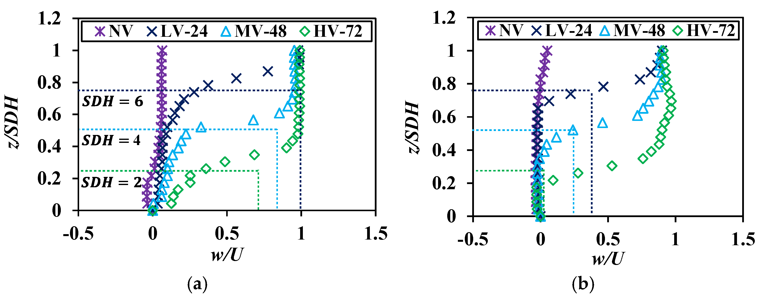
The vertical velocity distribution at P1 and P2, as depicted in Figure 10a,b, reveals a similar inflation trend across the examined cases. The velocity profiles demonstrate a clear relationship between the spur dike height (SDH) and the observed variations in vertical velocity. Specifically, the cases with SDH = 2, 4, and 6 cm indicated a progressive change in flow behavior with increasing spur dike height, showcasing the influence of spur dike geometry (submergence height and vegetation porosity) on vertical velocity behavior.
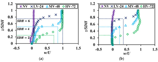
Figure 10.
The vertical distribution of depth-wise velocity distribution in vertical direction at (a) P1 and (b) P2.
In HV-72, the maximum vertical velocity distribution was observed, attributed to the spur dike’s high porosity of 72%. This significant porosity allows for enhanced porosity, facilitating vertical momentum exchange within the flow. The increased porosity effectively reduces the drag forces on the flow, allowing for higher vertical velocity distributions compared to less porous configurations. These findings are consistent with studies by Tominaga et al. [33], which highlighted the role of high-porosity vegetation in promoting vertical velocity distribution and minimizing energy losses in open-channel flows in the presence of a submerged vegetated dike. In contrast, cases with lower porosity and greater impermeable height exhibited reduced vertical-velocity magnitude. This reduction is attributable to the increased flow resistance associated with less porous configurations. As the impermeable portion of the spur dike increases, the ability of the flow to redistribute vertically diminishes, resulting in lower velocity profiles. The progressive inflation trend observed in the velocity distribution at P1 and P2 further underscores the impact of porosity and spur dike height on flow dynamics as well as their implications for sediment transport and scouring risks.
The observed trends also highlight the balance between porosity and flow resistance in vertical-velocity redistribution. While higher porosity, as in HV-72 case, enables greater vertical velocity and momentum exchange, it may also lead to reduced flow resistance and increased velocity gradients. These effects are advantageous in certain conditions, such as mitigating recirculation and enhancing sediment transport, but may require careful consideration in spur dike design to prevent excessive flow concentration and erosion downstream [23].
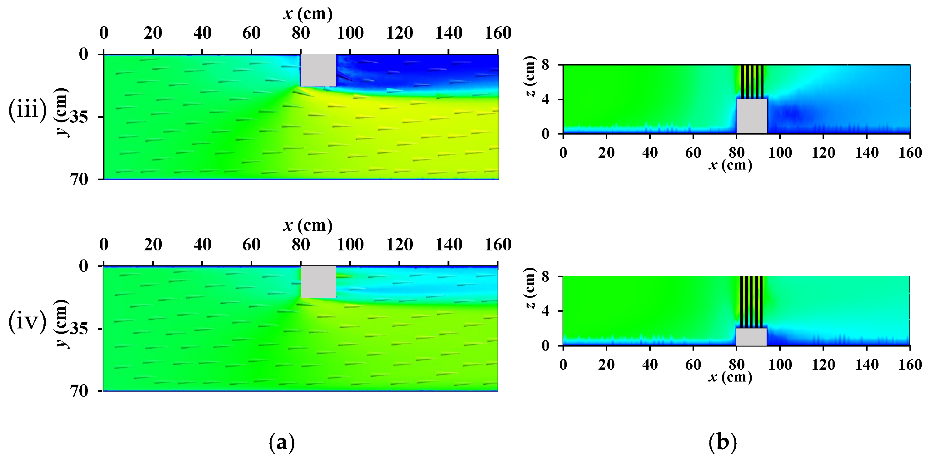
3.2.2. Flow Structure and Velocity Contours
The flow structure and velocity contours presented in Figure 11 illustrate the impact of partially and fully submerged spur dike configuration. Involving an emerged spur dike (NV) and submerged dikes with emergent vegetation (LV-24, MV-48, and HV-72), Figure 11 reveals how spur dike submergence and the presence of vegetation significantly alter flow patterns, including the formation and dissipation of recirculation zones, velocity profiles, and streamline behavior in the upstream and downstream regions. In NV, characterized by an impermeable and emerged spur dike without vegetation (Figure 11i), a pronounced recirculation zone forms immediately downstream of the dike. This high-velocity recirculation is a consequence of flow separation caused by the impermeable spur dike, which generates abrupt changes in momentum and pressure gradients at the downstream corner. Such regions are highly susceptible to erosion, as the concentrated vortex action exerts substantial shear stress on the adjacent riverbanks. This phenomenon has been widely reported in hydraulic studies [7,34,35], where impermeable spur dikes were found to create intense shear layers and localized erosion hotspots downstream. The presence of high-velocity flow within the recirculation region emphasizes the potential risks to bank stability, necessitating mitigation measures to reduce erosion and flow concentration near the dike.
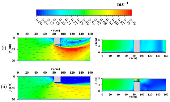
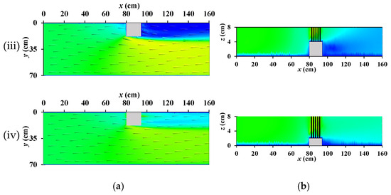
Figure 11.
Flow structure and velocity contours for (i) NV, (ii) LV-24, (iii) MH-48, and (iv) HV-72 measured at the (a) top of channel and (b) cross section at the mid of the spur dike.
In LV-24 and MV-48 cases, the addition of emergent vegetation to the submerged impermeable dike’s crest significantly alters the flow structure, effectively mitigating the recirculation phenomenon observed in NV case. The vegetation provides additional flow resistance and enhances energy dissipation, allowing for smoother momentum transfer downstream. As shown in Figure 11ii,iii, the recirculation region entirely disappears, and the flow transitions from high-velocity, concentrated zones to a more distributed and uniform velocity profile. These changes demonstrate the effectiveness of vegetation with different porosity in controlling flow patterns and reducing the intensity of turbulent zones downstream [36]. The absence of concentrated recirculation highlights the role of vegetation in minimizing shear stresses and promoting sediment deposition, thereby enhancing bank stability and reducing erosion risks. The sediment deposition will enhance the biodiversity allowing them to grow along the riverbank. Vegetation on spur dikes helps stabilize riverbanks by reducing erosion, particularly during flood events. The roots of the plants bind soil particles, reducing the risk of sediment displacement, and improving the overall stability of the river channel.
The HV-72 case, which features a submerged spur dike with a very small impermeable portion and emergent vegetation with maximum porosity of 72% (Figure 11iv), presents a distinct flow behavior, in both top (Figure 10a) and cross-sectional view (Figure 11a). Due to the minimal obstruction caused by the impermeable part of the dike, high-velocity flow transitions directly from the upstream to downstream regions without significant flow separation or turbulence. The high-concentration streamlines observed in the upstream region realign into parallel streamlines as they pass over the dike, indicating reduced flow disruption. This behavior can be attributed to the reduced resistance offered by the dike’s submerged and porous configuration [10,21,28,37], which links reduced impermeable surface areas to enhanced flow continuity and lower energy losses. While this configuration minimizes upstream flow obstruction, it results in the upstream region becoming a high-velocity zone, as seen in Figure 11iv. Such high velocities upstream may pose challenges for sediment deposition and scour mitigation near the dike’s base.
3.3. Turbulence Characteristics
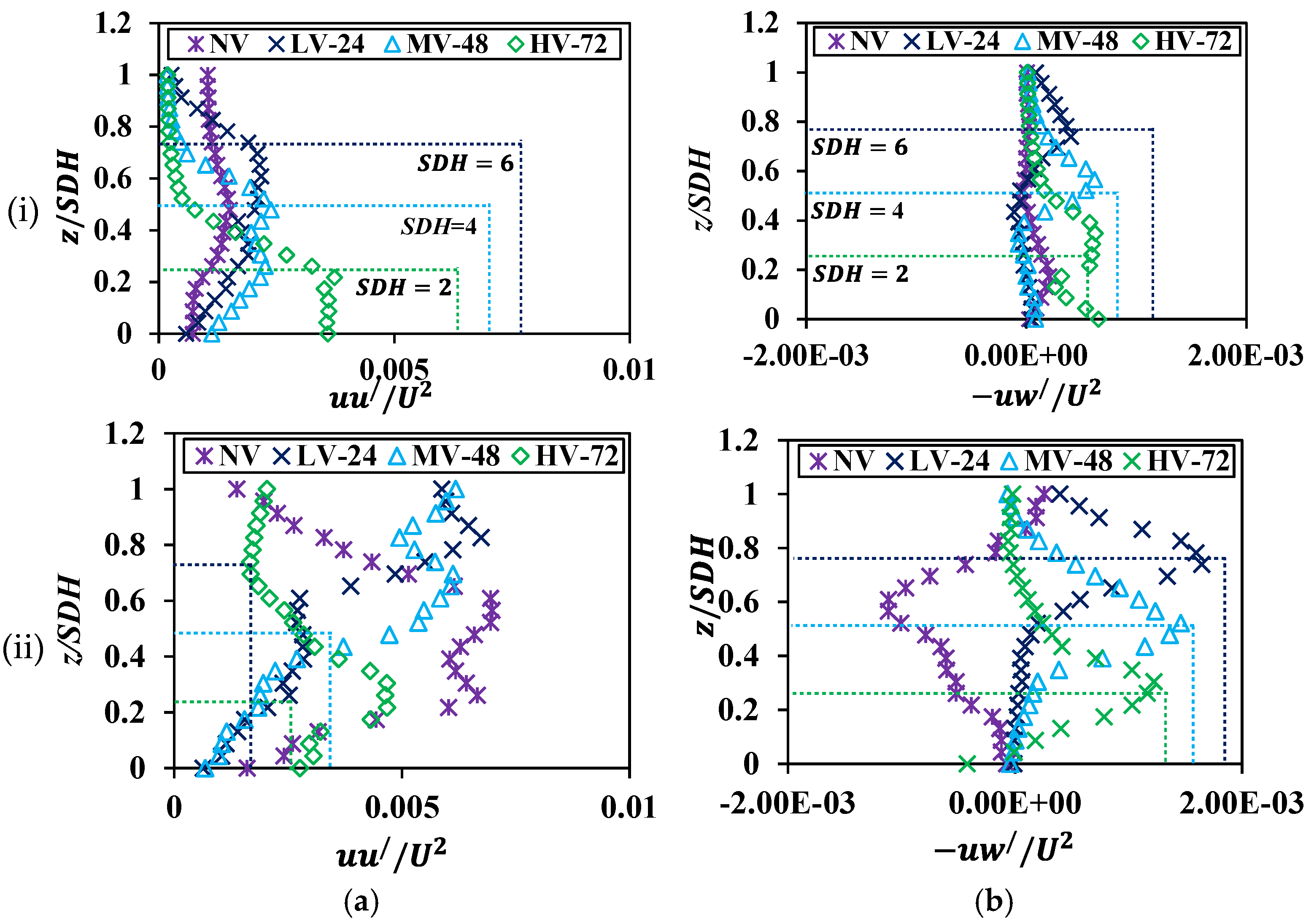
3.3.1. Reynold Stresses
The Reynolds normal and shear stresses distribution in the vertical direction at locations P1 and P2, as illustrated in Figure 12a and Figure 12b, respectively, shows a comprehensive understanding of the interaction between impermeable and vegetated spur dike components on turbulent flow behavior. To facilitate comparative analysis, the x-axis was made dimensionless with , representing the square of the initial velocity, and the z-axis by the SDH, the height of the permeable spur dike. These normalizations ensure that the results are dimensionless and enable direct comparisons across different spur dike configurations and heights. The results emphasize the impact of porosity, spur dike height, and the interface between impermeable and vegetated sections on the distribution of stresses at both upstream and downstream of the spur dike in vertical directions. At location P1, depicted in Figure 12i, NV, which features a fully impermeable spur dike, demonstrated no significant fluctuations in the vertical profiles of normal and shear stresses. This uniformity suggests that the impermeable spur dike induced minimal turbulence in the upstream region, leading to stable flow behavior. The lack of vegetation in NV eliminates the possibility of any substantial momentum exchange or shear generation at the spur dike surface, resulting in relatively low turbulence.
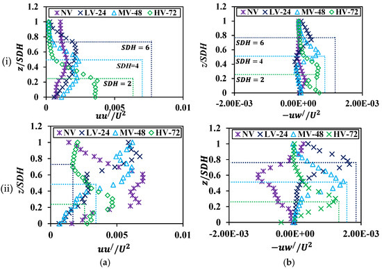
Figure 12.
The vertical distribution of (a) normal and (b) shear stresses at location (i) P1 and (ii) P2. The dashed lines show the height location of submerged impermeable spur dike (SDH).
In contrast, LV-24, MV-48, and HV-72, which incorporate vegetated sections into the spur dike design, exhibited maximum stresses at the interface between the impermeable and vegetated parts, corresponding to SDH = 2 cm, 4 cm, 6 cm. These maximum stresses occur due to the formation of a shear layer at the interface, which arises from the velocity gradient between the flow near the impermeable section and the vegetated section. This shear layer generates significant turbulence and concentrated stresses at the interface. From a structural design perspective, this emphasizes the need for reinforcement at the interface to withstand these stresses and prevent potential damage or erosion in such configurations. These elevated stresses arise from the sudden change in flow resistance as the flow transitions from the impermeable spur dike to the vegetated region. The abrupt interface generates localized turbulence and shear, driven by differences in velocity and momentum exchange between the two regions. This behavior is consistent with the previous research [38,39,40], which noted that transitions between impermeable and porous regions in hydraulic structures result in intensified turbulence and stress concentrations. Near the free surface, the stresses stabilized for all cases, reflecting reduced turbulence and flow acceleration in the upper layers where shear interactions are less pronounced.
At location P2, shown in Figure 12ii, the stress profiles displayed distinct patterns across the cases. NV exhibited the highest normal stresses but the lowest shear stresses in this region. The high normal stresses are attributed to the recirculation zones forming behind the impermeable dike, where flow stagnation leads to concentrated pressure gradients. Conversely, the low shear stresses, including negative values, are a direct consequence of the low-velocity regions created by the recirculation behavior downstream of the impermeable dike. These low velocities result in reduced velocity gradients, thereby minimizing the generation of shear stresses. Negative shear stresses, as observed in NV, occur due to flow reversal within the recirculation zone, which is a common phenomenon in flows obstructed by impermeable spur dikes. Similar findings were reported by Iqbal and Tanka [23], who demonstrated that recirculation zones downstream of impermeable spur dikes produce negative flow formation due to reverse flow behavior within the spur dike field.
When the porosity of the spur dike increased from 24% to 72%, the stress magnitudes at P2 showed a notable reduction. The introduction of vegetation and porous sections enhances the ability of the flow to dissipate energy and reduces the intensity of recirculation zones downstream. The LV-24 and MV-48 cases, which represent low and medium porosity levels, respectively, exhibited the highest overall stresses at P2. This is due to the combined effect of momentum exchange and localized turbulence at the interface of impermeable and vegetated sections. These cases create a balance between energy dissipation and turbulence generation, resulting in elevated stress levels. In contrast, HV-72, with the highest porosity, displayed the lowest stresses, both normal and shear, in this region. The high porosity of the spur dike allows for smoother flow transitions and minimizes resistance, leading to reduced turbulence and stress, which in turn decreases the risk of localized erosion near the vegetated sections.
The results at both P1 and P2 underscore the critical role of porosity and spur dike geometry in determining stress distributions. The NV, with its impermeable design, produces stable stress profiles upstream but leads to significant normal stresses and negative shear stresses downstream due to recirculation effects. The introduction of vegetation in porosity cases introduces enhanced turbulence and stress concentrations at the interface of impermeable and vegetated sections, particularly at P1. However, as porosity increases, the stresses at P2 are significantly reduced, highlighting the advantages of porous configurations in mitigating turbulent forces and promoting smoother flow transitions. This stress reduction at P2 is particularly important for long-term erosion mitigation strategies, as it reduces the potential for localized scouring and facilitates more uniform sediment transport and deposition downstream. The HV-72 case, with its high porosity, emerges as the most effective configuration for minimizing stress levels enhancing flow stability, and promoting sustainable erosion resistance.
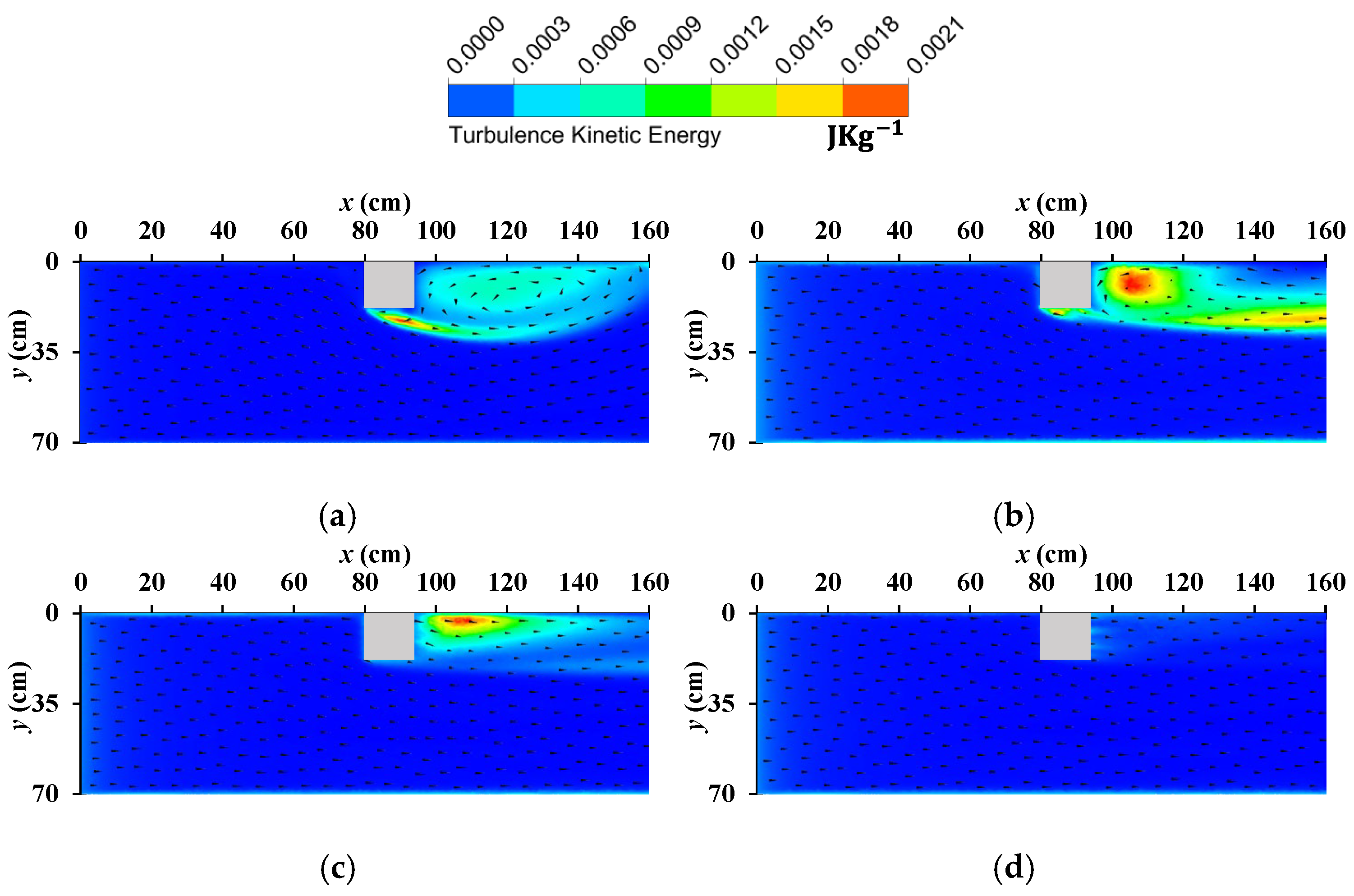
3.3.2. Turbulent Kinetic Energy
The turbulent kinetic energy (TKE) distributions presented in Figure 13a–d provide a detailed visualization of how different spur dike configurations influence turbulence generation and dissipation under emerged and submerged conditions. TKE, which represents the intensity of turbulence in the flow, is a key indicator of energy dissipation, mixing, and potential erosive forces. The analysis of the four cases highlights the critical differences between impermeable and porous spur dike designs, particularly in their ability to manage turbulence and ensure flow stability.
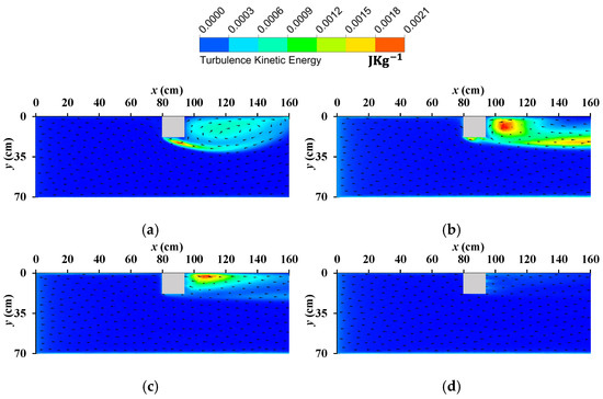
Figure 13.
Turbulent kinetic energy contours for (a) NV, (b) LV-24, (c) MH-48, and (d) HV-72 were measured at the top of the channel.
In the NV case, the fully impermeable spur dike exhibits significant turbulence downstream, as shown by the high concentration of TKE near the recirculation zone. The impermeable spur dike creates a sharp flow separation at its downstream interface, leading to the formation of strong vortices and elevated energy dissipation. This phenomenon is a direct consequence of the abrupt momentum exchange caused by the impermeable spur dike, which obstructs the flow entirely and forces it to navigate around it. The localized turbulence downstream not only increases the risk of structural damage to the spur dike but also poses a substantial threat to bank stability due to erosion. This is particularly problematic in submerged conditions, where the higher flow velocities over the spur dike exacerbate turbulence and enhance erosive forces. These negative aspects of impermeable spur dikes have been reported previously [23,41], which emphasizes the inefficiency of impermeable structures in mitigating turbulent energy under high-flow conditions. The inability of the impermeable spur dike to dissipate energy effectively underscores its limitations in submerged scenarios, making it less suitable for applications where erosion control and structural stability are critical.
The LV-24, which introduces vegetation on top of the impermeable spur dike, demonstrates significant improvements in managing turbulence under submerged conditions. The addition of vegetation creates a layer of increased flow resistance that disrupts the formation of high-energy vortices, thereby reducing the intensity of turbulence downstream. Although some localized turbulence remains near the interface between the impermeable spur dike and the vegetated section, the overall TKE is considerably lower than in NV. This reduction highlights the positive role of vegetation in dissipating energy and enhancing flow stability. Vegetation acts as a natural buffer, slowing down the flow and distributing turbulent energy more evenly across the flow field. This mitigates the risk of erosion and reduces the potential for structural damage to the spur dike and its surroundings. The improved performance of LV-24 under submerged conditions aligns with the findings of Aziz and Kadota [42], who observed that vegetation significantly reduces turbulent energy and promotes sediment deposition, thereby enhancing bank stability. The inclusion of vegetation also helps to balance the momentum exchange across the flow, minimizing the sharp velocity gradients that are characteristic of impermeable spur dikes.
In Figure 13c, where the spur dike incorporates a higher level of porosity alongside vegetation, the performance is further improved under submerged conditions. The increased porosity allows a greater portion of the flow to pass through the dike, reducing the overall resistance and minimizing the sharp momentum changes observed in NV and LV-24. The result is a more distributed and less intense TKE profile, with significantly reduced turbulence downstream. Unlike the impermeable spur dike in NV, which generates concentrated turbulence, MV-48 facilitates smoother flow transitions and dissipates energy more effectively. This makes MV-48 particularly well-suited for submerged conditions, where high flow velocities can otherwise lead to severe turbulence and erosion. The combination of porosity and vegetation creates an ideal balance between flow resistance and energy dissipation, ensuring that turbulent forces are kept to a minimum while maintaining spur dike stability.
4. Discussion
The findings of this study reveal the critical role of vegetation porosity in enhancing the performance of submerged spur dikes for flow control and bank protection in river systems. Impermeable dikes without vegetation, as in the NV case, produce strong recirculation zones downstream, leading to significant turbulence and increased erosion risks. These three zones formation (weak, strong, and intermediate diffusion, as shown in Figure 2b), are driven by sharp flow separation, concentrating turbulent kinetic energy and Reynolds stresses, creating localized areas of high energy dissipation. Such behavior not only compromises the stability of the spur dike structure but also accelerates the degradation of adjacent riverbanks, making NV dikes less effective for sustainable hydraulic management [23]. Introducing vegetation with different porosity (24%, 48%, and 72%) in terms of their height (low vegetation (LV); medium vegetation (MV), and high vegetation (HV)), significantly alters the flow structure and turbulence distribution, as demonstrated in LV-24 and MV-48 configurations. These moderately porous designs successfully disrupt recirculation zones and mitigate momentum concentration downstream. The LV-24 configuration reduces high-velocity zones near the spur dike, while MV-48 further enhances energy dissipation and smoothens flow transitions, balancing turbulence and stability. The results underscore that moderate vegetation porosity effectively minimizes adverse flow patterns, promoting sediment deposition and reducing erosion risks. This performance aligns with existing studies that emphasize the importance of porosity in mitigating shear stresses and ensuring hydraulic efficiency in submerged conditions.
The findings of this study align with existing research emphasizing the critical role of porosity in enhancing hydraulic performance. Similar to prior investigations, the results confirm that moderate porosities (e.g., LV-24 and MV-48) effectively reduce turbulence and promote smoother flow transitions by mitigating recirculation zones downstream. This aligns with studies by Tominaga et al. [33] and Haider et al. [3], which demonstrated the benefits of porosity in minimizing energy dissipation and controlling shear stresses around spur dikes. Additionally, the observed reduction in turbulent kinetic energy in vegetated configurations supports the findings of Iqbal et al. [12] who noted the role of vegetation in enhancing sediment deposition and reducing erosion risks. However, the current study diverges in highlighting the limitations of high porosity (HV-72). While previous research often emphasized the hydraulic efficiency of permeable dikes, this study identifies trade-offs, including reduced energy dissipation upstream and increased downstream flow instability. Unlike impermeable designs, the HV-72 configuration exhibited smoother streamlined alignment but was less effective in controlling downstream velocities, posing potential risks for localized sediment displacement. This nuanced understanding underscores the need for optimizing porosity levels and balancing hydraulic performance with erosion control, and aligns with findings by Zhang and Nakagawa [34], who highlighted similar trade-offs in permeable dike designs.
Conversely, the HV-72 case highlights the trade-off between porosity and flow resistance. While high vegetation porosity reduces turbulence and facilitates smoother streamlined alignment, it also diminishes the dike’s ability to dissipate energy effectively upstream. The reduced resistance in HV-72 allows excessive flow through the structure, limiting its protective impact and increasing the risk of downstream instability. Although reduced turbulence minimizes localized stress, smoother flow transitions can lead to elevated downstream velocities, which increases sediment transport and the potential for scouring in these areas. This finding demonstrates that overly high porosity, while beneficial for flow continuity, may compromise the dike’s erosion control capability. The analysis of velocity and stress distributions further emphasizes the superiority of LV-24 and MV-48 configurations. Compared to NV, these configurations achieve substantial reductions in turbulent kinetic energy and shear stress while maintaining effective energy dissipation. The moderate porosity levels enable controlled turbulence and smooth momentum exchange at the interface between impermeable and vegetated sections, minimizing erosion and promoting stability. While HV-72 achieves low turbulence, its inability to control downstream velocities highlights the importance of optimizing porosity levels for balanced hydraulic performance that effectively mitigates erosion while maintaining flow stability. Moreover, vegetation encourages biodiversity by offering shelter, breeding grounds, and food sources for various organisms.
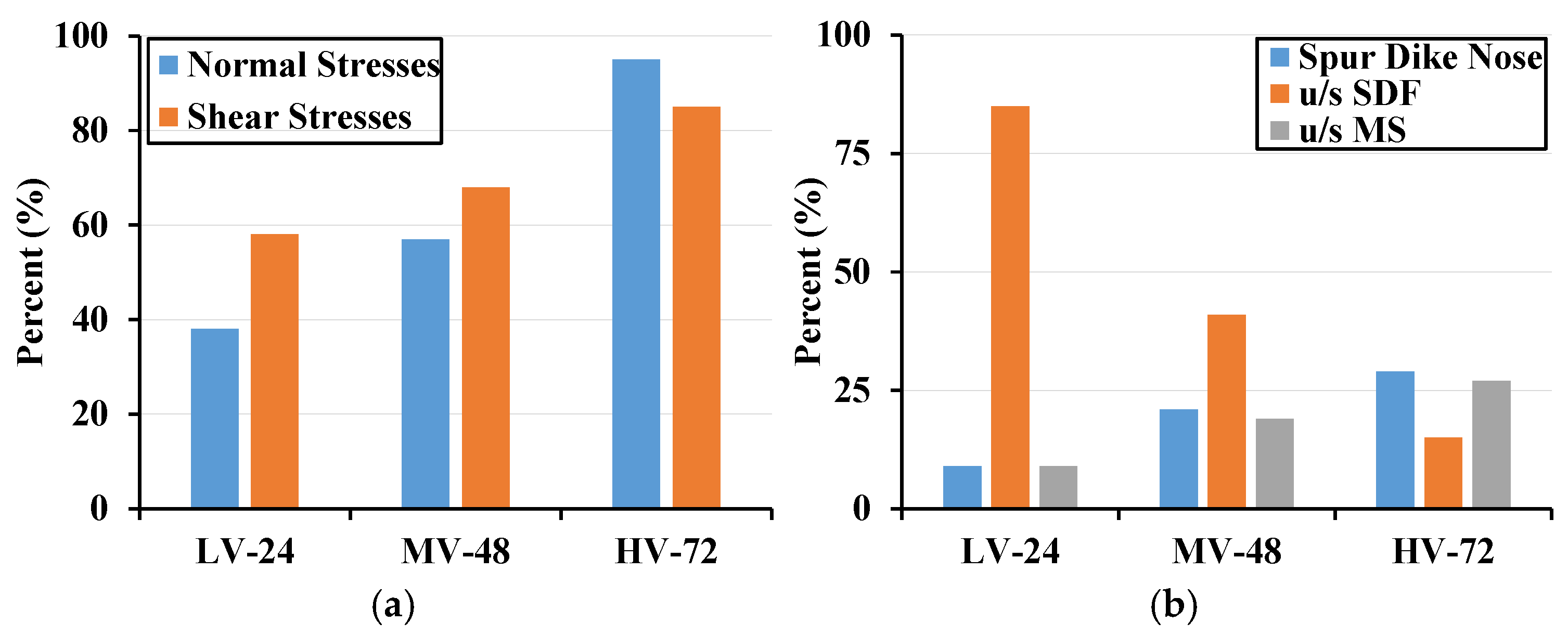
Figure 14 provides a comparative summary of key performance metrics for different spur dike configurations (LV-24, MV-48, and HV-72), focusing on stress distribution and velocity characteristics at critical regions. Figure 14a illustrates the normal and shear stress distributions on the spur dike. As porosity increases, normal stresses significantly rise, with HV-72 exhibiting an approximately 80% higher normal stress compared to LV-24. This indicates that higher porosity leads to a more uniform distribution of flow forces across the dike structure, reducing localized pressure peaks. Shear stresses also show a consistent increase with porosity, though to a lesser extent, suggesting that porous configurations effectively reduce stagnation zones and turbulence near the dike. Figure 14b highlights the velocity distributions at three critical locations: the spur dike nose, the upstream spur dike field (u/s SDF), and the upstream mainstream (u/s MS). Near the spur dike nose, velocities are lowest for all configurations, with LV-24 showing the smallest value due to its lower porosity and greater resistance to flow. In the u/s SDF, velocity progressively increases with porosity, with HV-72 demonstrating a 100% increase compared to LV-24. This trend indicates that higher porosity facilitates better flow penetration and minimizes stagnation effects in the spur dike field. Similarly, in the u/s MS, velocity increases are more moderate, with HV-72 exhibiting a 50% higher velocity compared to LV-24, reflecting smoother flow transitions into the mainstream. These findings underline the necessity of incorporating moderate porosity vegetation into spur dike designs to optimize their protective performance under submerged conditions. The LV-24 and MV-48 configurations outperform both impermeable dikes and highly porous designs, offering a sustainable and efficient solution for erosion control and flow management. By balancing energy dissipation, turbulence reduction, and flow resistance, these designs contribute to improved hydraulic efficiency and support sustainable river management strategies. This study highlights the potential of combining vegetation and porosity in spur dike designs, advancing the understanding of their role in mitigating erosion and enhancing the stability of river systems. A concise Table 3 summarizing the velocity, stress, and turbulence outcomes for each configuration has been added for comparison purposes.
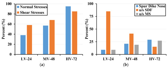
Figure 14.
Comparative summary of key performance metrics, including (a) normal and shear-stress distributions and (b) velocity percentages reduction at critical locations: spur dike nose, upstream spur dike field (u/s SDF), and upstream mainstream (u/s MS).
Table 3.
Configuration Outcomes Summary.
5. Conclusions
This study numerically analyzed the effects of vegetation porosity on the hydraulic performance of submerged spur dikes, focusing on flow control and bank protection in river systems. By employing a validated computational fluid dynamics (CFD) model, various configurations of vegetated dikes, ranging from impermeable to highly porous, were evaluated under submerged conditions. The findings provide significant insights into the critical role of vegetation porosity in stabilizing flow, reducing turbulence, and mitigating erosion risks. The following are the key conclusions,
The results demonstrated that impermeable spur dikes without vegetation (NV) are prone to generating strong recirculation zones downstream, characterized by high turbulent kinetic energy (TKE) and sharp velocity gradients. These effects exacerbate sediment erosion and compromise bank stability, making NV spur dikes less effective under submerged conditions. In contrast, vegetated spur dikes with low and medium porosities (LV-24 and MV-48) significantly enhanced flow performance. By introducing moderate vegetation porosity, these configurations disrupted recirculation zones, reduced downstream velocity, and promoted energy dissipation, effectively addressing the shortcomings of impermeable dikes. LV-24 was particularly effective in minimizing high-velocity zones, while MV-48 further optimized the balance between flow resistance and turbulence mitigation.
Highly porous configurations (HV-72) reduced turbulence intensity and allowed smoother streamlined alignment but exhibited diminished protective capabilities due to excessive flow through the structure. This resulted in less-effective energy dissipation upstream and potential instability in downstream sediment transport. The findings underscore the trade-offs associated with high porosity, emphasizing that moderate porosities (24% and 48%) offer the best balance between hydraulic performance and structural stability.
Velocity and stress distributions further validated the superior performance of moderate porosity dikes. The analysis revealed that LV-24 and MV-48 effectively minimized shear and normal stresses at critical locations around the spur dike, promoting smoother flow transitions and reducing localized erosion. These configurations also redistributed turbulent energy more evenly, ensuring long-term stability and efficiency under submerged conditions. Conversely, the impermeable spur dike exhibited concentrated stresses and negative shear stress in recirculation zones, highlighting its limitations in turbulence management.
These findings have important real-world applications, particularly for flood-prone regions where erosion control and flow management are critical. The use of moderate-porosity vegetated spur dikes can help stabilize riverbanks, reduce sediment transport risks, and improve floodplain resilience. In such areas, these configurations provide an effective solution for mitigating the impact of extreme hydrodynamic conditions, ensuring both hydraulic efficiency and long-term stability.
Overall, this study establishes that integrating vegetation with moderate porosity into submerged spur dike designs can significantly improve their hydraulic performance. In field applications, the use of vegetated dikes can significantly reduce maintenance costs by minimizing erosion and sedimentation around riverbanks. The gradual dissipation of energy downstream ensures that sediment transport is evenly distributed, preventing localized deposition or scouring that could destabilize the spur dike or adjacent infrastructure. Moreover, the flexibility in spur dike design allows engineers to adapt the porosity and vegetation type based on site-specific conditions, such as flow intensity, sediment load, and ecological requirements. This adaptability makes vegetated dikes a versatile tool for river restoration and flood control projects. Despite these promising outcomes, there remain critical research gaps to address in future studies. While this study focused on the hydraulic performance of vegetated dikes under controlled conditions, further research is needed to evaluate their long-term effectiveness under varying environmental scenarios, such as extreme flood events or changing sediment loads. Additionally, understanding the ecological implications of using different vegetation types and densities is crucial for integrating these designs into broader riverine ecosystem management plans. The interaction between vegetation growth dynamics and hydraulic performance over time also warrants further investigation, as natural changes in vegetation density could influence spur dike efficiency. In this study, the focus was placed on internal flow dynamics and the influence of vegetation porosity on a single submerged spur dike. While the modeling framework effectively captures key flow characteristics, advanced methods such as Volume of Averaging (VOA), Volume of Fluid (VOF), and Higher Order Averaging (HOA) could further enhance the accuracy of vertical flow calculations, especially near complex structures like spur dikes provided in a series compared to single spur dike. These methods have been shown to improve the representation of vertical flow interactions in similar studies. Future research could integrate these techniques to provide a more comprehensive understanding of vertical flow patterns, turbulence distribution, and their implications for hydraulic and ecological performance. Moreover, investigating the impact of sedimentation dynamics over time would provide valuable insights into the long-term performance of spur dike configurations. This aspect, including the interactions between flow structures, sediment transport, and deposition patterns, is an important avenue for future research.
Author Contributions
Conceptualization, S.I., R.H. and G.A.P.; writing—original draft preparation, S.I. and R.H.; methodology, R.H. and S.I.; formal analysis, G.A.P., L.Z., F.M.A. and N.A.; investigation, L.Z., N.A., N.M., F.M.A. and Z.A.; data curation, R.H. and S.I.; writing—review and editing, G.A.P., L.Z., N.A., N.M. and Z.A.; supervision, S.I., G.A.P. and L.Z. All authors have read and agreed to the published version of the manuscript.
Funding
This research received no external funding.
Data Availability Statement
Data is contained within the article.
Conflicts of Interest
The authors declare no conflicts of interest.
References
- Asghar, M.; Pasha, G.A.; Ghani, U.; Iqbal, S.; Jameel, M.S. Investigating multiple debris impact load and role of vegetation in protection of house model during floods. In Proceedings of the 2nd Conference on Sustainability in Civil Engineering, Virtual, 2 August 2020. [Google Scholar]
- Brevis, W.; García-Villalba, M.; Niño, Y. Experimental and large eddy simulation study of the flow developed by a sequence of lateral obstacles. Environ. Fluid Mech. 2014, 14, 873–893. [Google Scholar] [CrossRef]
- Haider, R.; Qiao, D.; Yan, J.; Ning, D.; Pasha, G.A.; Iqbal, S. Flow Characteristics Around Permeable Spur Dike with Different Staggered Pores at Varying Angles. Arab. J. Sci. Eng. 2022, 47, 5219–5236. [Google Scholar] [CrossRef]
- Pasha, G.A.; Ghumman, A.R.; Naseer, M.J.; Iqbal, S.; Ahmed, A. Flow Characteristics in a Two-Stage Vegetated Compound Trapezoidal Channel. Iran. J. Sci. Technol. Trans. Civ. Eng. 2023, 47, 505–517. [Google Scholar] [CrossRef]
- Iqbal, S.; Siddique, M.; Hamza, A.; Murtaza, N.; Pasha, G.A. Computational analysis of fluid dynamics in open channel with the vegetated spur dike. Innov. Infrastruct. Solut. 2024, 9, 345. [Google Scholar] [CrossRef]
- Okamoto, T.; Okazaki, T.; Takenaka, M.; Sanjou, M.; Toda, K. Experimental Study on Horse Shoe Vortex and Coherent Vortex around Vegetated Groyne. J. Jpn. Soc. Civ. Eng. Ser. A2 (Appl. Mech. (AM)) 2018, 74, I_431–I_438. [Google Scholar]
- Pandey, M.; Ahmad, Z.; Sharma, P.K. Scour around impermeable spur dikes: A review. ISH J. Hydraul. Eng. 2018, 24, 25–44. [Google Scholar] [CrossRef]
- Azinfar, H.; Kells, J.A. Drag force and associated backwater effect due to an open channel spur dike field. J. Hydraul. Res. 2011, 49, 248–256. [Google Scholar] [CrossRef]
- Shampa; Hasegawa, Y.; Nakagawa, H.; Takebayashi, H.; Kawaike, K. Three-dimensional flow characteristics in slit-type permeable spur dike fields: Efficacy in riverbank protection. Water 2020, 12, 964. [Google Scholar] [CrossRef]
- Kuhnle, R.A.; Jia, Y.; Alonso, C.V. Measured and Simulated Flow near a Submerged Spur Dike. J. Hydraul. Eng. 2008, 134, 916–924. [Google Scholar] [CrossRef]
- Radan, P.; Vaghefi, M. Flow and scour pattern around submerged and non-submerged T-shaped spur dikes in a 90° bend using the SSIIM model. Int. J. River Basin Manag. 2016, 14, 219–232. [Google Scholar] [CrossRef]
- Anjum, N.; Iqbal, S.; Tanaka, N. Impact of floating vegetation island on velocity distribution in open channel flow. Model. Earth Syst. Environ. 2023, 10, 1631–1645. [Google Scholar] [CrossRef]
- Safie, O.; Tominaga, A. EEffects of pile density and arrangement on flow characteristics and sediment deposition around a pile-group dike. J. Jpn. Soc. Civ. Eng. Ser. A2 (Applied Mech. (AM)) 2019, 75, I_487–I_498. [Google Scholar] [CrossRef]
- Iimura, K.; Tanaka, N. Numerical simulation estimating effects of tree density distribution in coastal forest on tsunami mitigation. Ocean Eng. 2012, 54, 223–232. [Google Scholar] [CrossRef]
- Scheres, B.; Schüttrumpf, H. Investigating the erosion resistance of different vegetated surfaces for ecological enhancement of sea dikes. J. Mar. Sci. Eng. 2020, 8, 519. [Google Scholar] [CrossRef]
- Xiang, K.; Yang, Z.; Wu, S.; Gao, W.; Li, D.; Li, Q. Flow hydrodynamics of the mixing layer in consecutive vegetated groyne fields. Phys. Fluids 2020, 32, 065110. [Google Scholar] [CrossRef]
- Sukhodolov, A.N. Hydrodynamics of groyne fields in a straight river reach: Insight from field experiments. J. Hydraul. Res. 2014, 52, 105–120. [Google Scholar] [CrossRef]
- Fukuoka, S.; Watanabe, A.; Ohashi, M.; Himeno, Y. Possibility of the use of Vegetation groin. Proc. Hydraul. Eng. 1997, 41, 1129–1132. [Google Scholar] [CrossRef]
- Wang, C.; Zheng, S.; Wang, P.; Hou, J. Interactions between vegetation, water flow and sediment transport: A review. J. Hydrodyn. 2015, 27, 24–37. [Google Scholar] [CrossRef]
- Davis, M.M.; Mitchell, W.A.; Wakeley, J.S.; Fischenich, J.C.; Craft, M.M. Environmental Value of Riparian Vegetation; US Army Corps of Engineers, Waterways Experiment Station [Environmental Laboratory]: Vicksburg, MS, USA, 1996. [Google Scholar]
- Nepf, H.; Ghisalberti, M. Flow and transport in channels with submerged vegetation. Acta Geophys. 2008, 56, 753–777. [Google Scholar] [CrossRef]
- Wilson, C.; Stoesser, T.; Bates, P.D.; Pinzen, A.B. Open Channel Flow through Different Forms of Submerged Flexible Vegetation. J. Hydraul. Eng. 2003, 129, 847–853. [Google Scholar] [CrossRef]
- Iqbal, S.; Tanaka, N. Experimental Study on Flow Characteristics and Energy Reduction Around a Hybrid Dike. Int. J. Civ. Eng. 2023, 21, 1045–1059. [Google Scholar] [CrossRef]
- Malalasekera, W.; Versteeg, H. An Introduction to Computational Fluid Dynamics: The Finite Volume Method; Pearson Education India: Delhi, India, 2007. [Google Scholar]
- Gu, Z.; Cao, X.; Jiao, Y.; Lu, W.-Z. Appropriate CFD Models for Simulating Flow around Spur Dike Group along Urban Riverways. Water Resour. Manag. 2016, 30, 4559–4570. [Google Scholar] [CrossRef]
- Takemura, T.; Tanaka, N. Flow structures and drag characteristics of a colony-type emergent roughness model mounted on a flat plate in uniform flow. Fluid Dyn. Res. 2007, 39, 694–710. [Google Scholar] [CrossRef]
- Wu, W.; Asce, M.; Kang, J.; Yeo, H.; Kuhnle, R.A.; Alonso, C.V.; Shields, F.D.; Chamani, R.; Rajaratnam, N.; Beirami, M.K.; et al. Ghani, three-dimensional computation of flow around groyne By Sylvain Ouillon 1 and Denis Dartus 2. J. Hydraul. Eng. 2011, 18, 97–105. [Google Scholar] [CrossRef]
- Chanson, H. Hydraulics of Open Channel Flow; Elsevier: Amsterdam, The Netherlands, 2004. [Google Scholar]
- Nandhini, D.; Murali, K.; Harish, S.; Schüttrumpf, H.; Heins, K.; Gries, T. A state-of-the-art review of normal and extreme flow interaction with spur dikes and its failure mechanism. Phys. Fluids 2024, 36, 051301. [Google Scholar] [CrossRef]
- Hakim, M.; Yarahmadi, M.B.; Kashefipour, S.M. Use of spur dikes with different permeability levels for protecting bridge abutment against local scour under unsteady flow conditions. Can. J. Civ. Eng. 2022, 49, 1842–1854. [Google Scholar] [CrossRef]
- Iqbal, S.; Tanaka, N. Hydraulic performance assessment of various submerged pile designs around an emerged dike. Water Sci. Eng. 2024, 17, 406–416. [Google Scholar] [CrossRef]
- Shiono, K.; Knight, D.W. Turbulent open-channel flows with variable depth across the channel. J. Fluid Mech. 1991, 222, 617–646. [Google Scholar] [CrossRef]
- Tominaga, A.; Safie, O.; Komura, H. Flow structures around laterally and vertically hybrid spur dike. In River Flow, 2020; CRC Press: Boca Raton, FL, USA, 2020; pp. 185–193. [Google Scholar]
- Zhang, H.; Nakagawa, H. Characteristics of local flow and bed deformation at impermeable and permeable spur dykes. Annu. J. Hydraul. Eng. JSCE 2009, 53, 145–150. [Google Scholar]
- Ahmed, H.; Hasan, M.; Tanaka, N. Analysis of flow around impermeable groynes on one side of symmetrical compound channel: An experimental study. Water Sci. Eng. 2010, 3, 56–66. [Google Scholar]
- Zey, S.; Nowroozpour, A.; Lachhab, A.; Martinez, E.; Ettema, R. Wall-Porosity Effects on Sediment Deposition and Scour at a Deflector Wall in an Alluvial Channel. J. Hydraul. Eng. 2018, 144, 06018002. [Google Scholar] [CrossRef]
- Nakamura, M.; Shiraishi, H.; Sasaki, Y. Wave damping effect of submerged dike. In Coastal Engineering; American Society of Civil Engineers: Reston, VA, USA, 1966; pp. 254–267. [Google Scholar]
- Qin, J.; Zhong, D.; Wu, T.; Wu, L. Sediment Exchange Between Groin Fields and Main-Stream. Adv. Water Resour. 2017, 108, 44–54. [Google Scholar] [CrossRef]
- Wu, T.; Qin, J. Influence of Flow and Sediment Transport Processes on Sedimentation in Groyne Fields. J. Coast. Res. 2020, 95, 304–308. [Google Scholar] [CrossRef]
- Molinas, A.; Kheireldin, K.; Wu, B. Shear Stress around Vertical Wall Abutments. J. Hydraul. Eng. 1998, 124, 822–830. [Google Scholar] [CrossRef]
- Mohammed, A.; Pervin, R. Hasan, M.Z. Effect of Various Groins in a Series on Channel Bed Morphology: An Experimental Investigation. Stavební Obz.-Civ. Eng. 2022, 31, 211–221. [Google Scholar] [CrossRef]
- Aziz, P.; Kadota, A. Experimental Study of Morphological Changes and Flow Structure around the Vegetated Groyne. Int. J. Adv. Sci. Eng. Inf. Technol. 2018, 8, 99–107. [Google Scholar] [CrossRef]


Disclaimer/Publisher’s Note: The statements, opinions and data contained in all publications are solely those of the individual author(s) and contributor(s) and not of MDPI and/or the editor(s). MDPI and/or the editor(s) disclaim responsibility for any injury to people or property resulting from any ideas, methods, instructions or products referred to in the content. |
© 2025 by the authors. Licensee MDPI, Basel, Switzerland. This article is an open access article distributed under the terms and conditions of the Creative Commons Attribution (CC BY) license (https://creativecommons.org/licenses/by/4.0/).