
Depositional Architecture of Aggrading Delta Front Distributary Channels and Corresponding Depositional Evolution Process in Ordos Basin: Implications for Deltaic Reservoir Prediction

Abstract
:1. Introduction
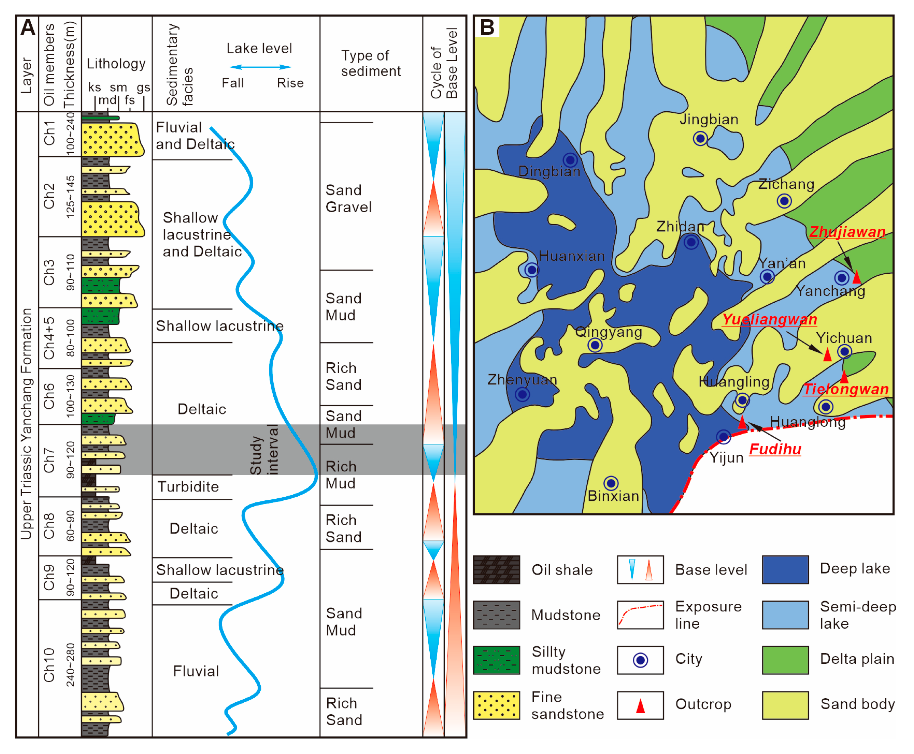
2. Geological Setting
3. Data and Methods
4. Results and Analysis
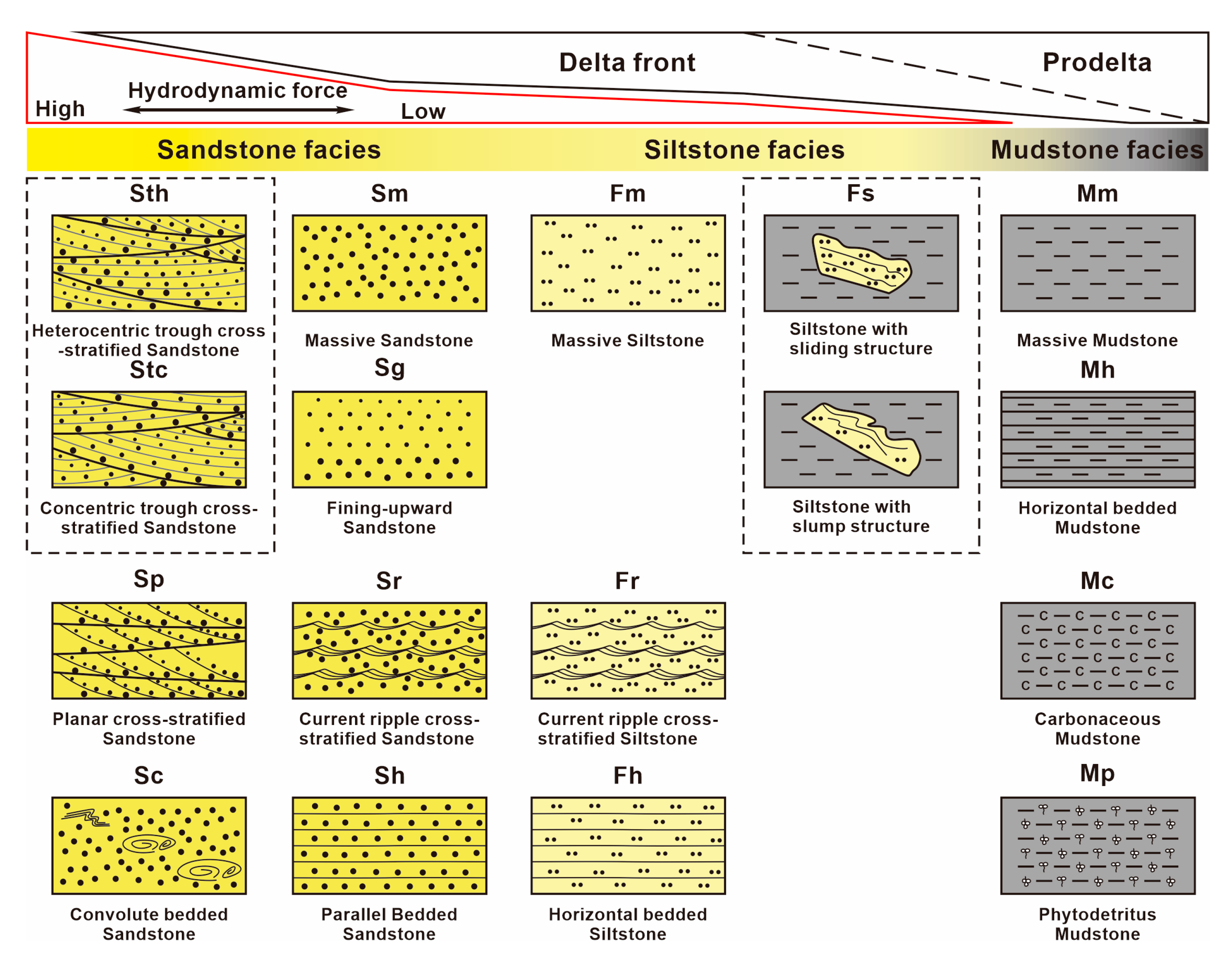
4.1. Lithofacies Analysis

| Lithofacies Code | Lithofacies Title | Grain Size | Thickness Range (m) | Description | Interpretation |
|---|---|---|---|---|---|
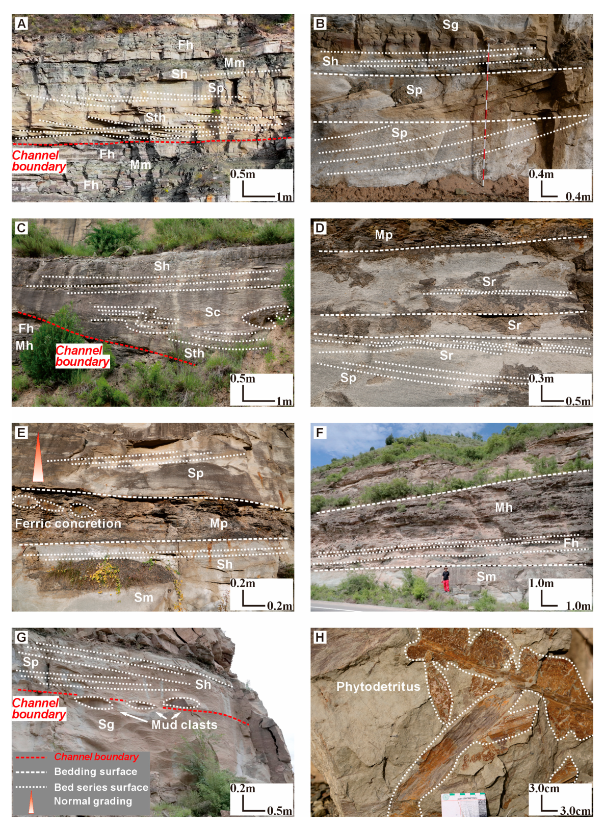
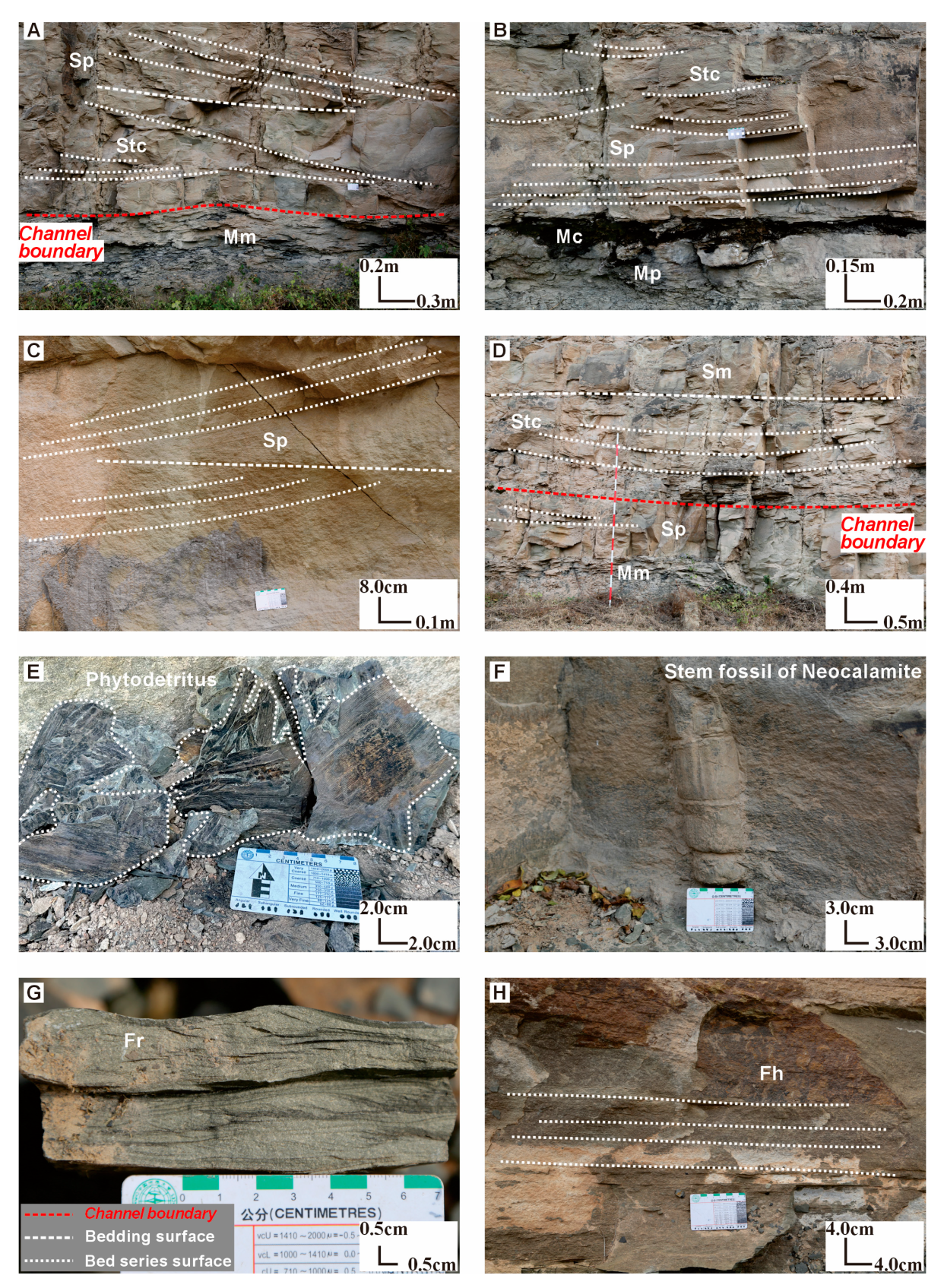
| Sth | Heterocentric trough cross-stratified Sandstone | Coarse to medium-grained sand | 0.50–3.00 | Lithofacies Sth occurs at the base of grayish-white sandstone. Its lower boundary has a curved erosional surface where troughed sets intersect consistent lamina planes at oblique angles. There are varying degrees of depression between the cross-bedded sets, with trough widths ranging from 1.0 to 3.0 m (Figure 3 and Figure 4A,C). | Trough cross-bedding forms at the base of a channel due to intense hydrodynamic erosion linked to channel incision [66]. Lithofacies Sth indicates channel migration [67]. |
| Stc | Concentric trough cross-stratified Sandstone | Coarse to medium-grained sand | 0.50–2.00 | Lithofacies Stc consists of well-sorted, rounded gray-white sandstone. The base exhibit subtle erosion surface. The troughs exhibit symmetrical shapes, with rapidly varying thicknesses and concave bottoms. The concave laminae and sets are consistent and vertically stacked. The trough widths range from 1.0 to 2.0 m (Figure 3 and Figure 5A,B,D). | Trough cross-bedding forms at the base of a channel as a result of strong hydrodynamic erosion associated with channel incision. Lithofacies Stc reflects rapid channel infilling [68,69]. |
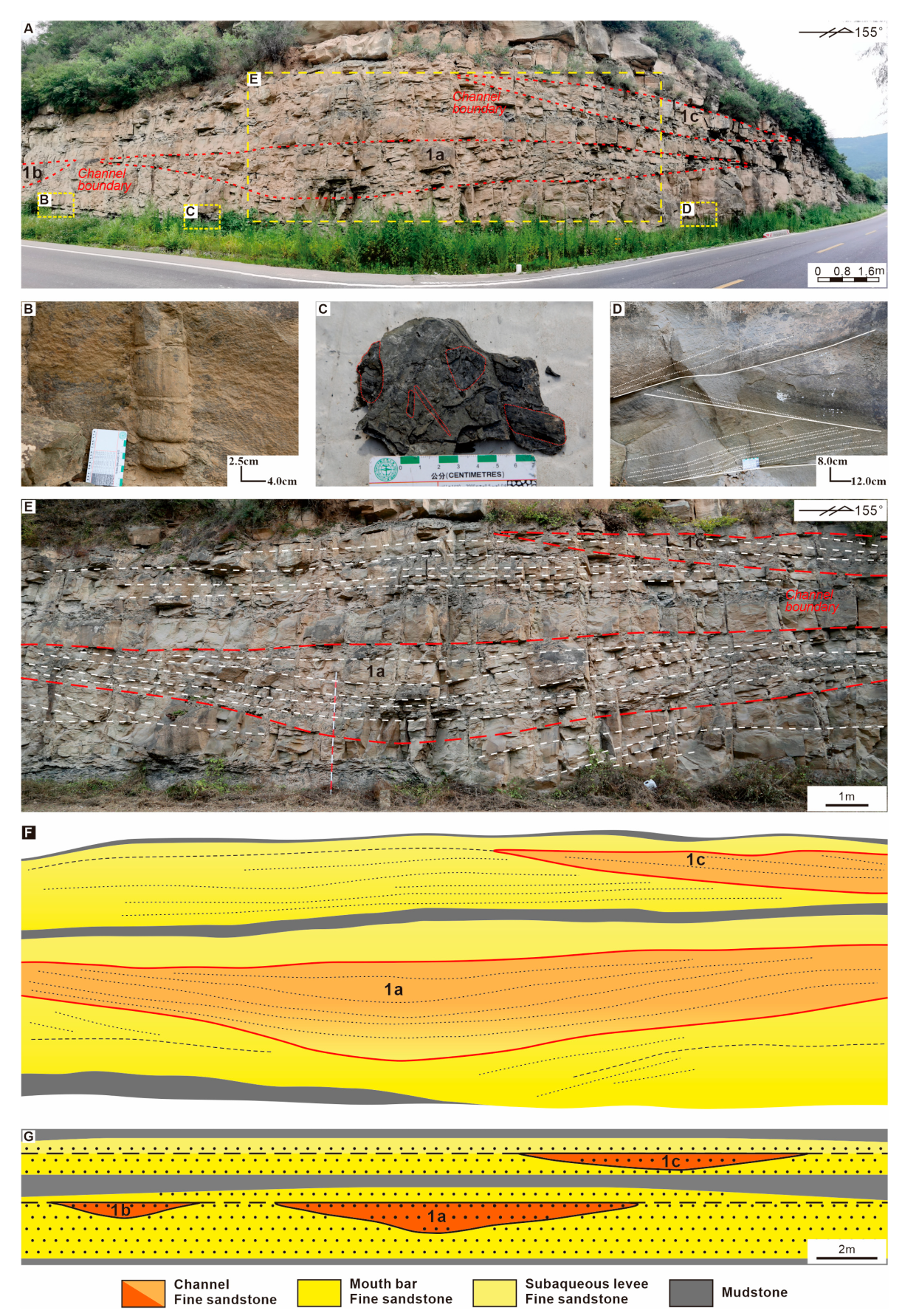
| Sp | Planar cross-stratified Sandstone | Coarse to medium-grained sand | 0.50–5.00 | The cross-bedding is observed at the base of the sets within gray-white sandstone. The sets exhibit a flat, parallel, and plate-like morphology, with minimal variation in thickness. The laminae intersect the sets at various angles, with the majority of laminae within a set aligned in the same direction. The angle between the laminae and the sets exceeds 10° (Figure 3 and Figure 4B,D,E,G). | Lithofacies Sp reflects the lateral or foreset deposition of sediments transported by strong forces. The cross-bedding indicates the downstream flow direction of bedload migration and typically forms within the microfacies of distributary channels and mouth bars [70,71]. |
| Sc | Convolute bedded Sandstone | Medium to fine-grained sand | 0.30–1.00 | Convolute bedding is observed in gray sandstone, characterized by continuous open “synclines” and tight “anticlines” (Figure 3). The distorted laminae gradually return to their normal orientation toward the base of the rock layer and are truncated by the overlying strata, with diameters ranging from 0.3 to 0.8 m (Figure 4C). | During flooding, channel overflow generated excessive vertical force at the edges, causing sediment to roll and deposit into the interdistributary bay. This process led to the curling of internal sediment layers, forming convolute bedding [72,73]. |
| Sm | Massive Sandstone | Medium to fine-grained sand | 0.20–2.00 | The rock stratum consists of well-sorted gray sandstone, positioned above St and Sp (Figure 5D). It is characterized by a uniform appearance and the absence of laminae, with a relatively consistent composition and structure (Figure 3). | Lithofacies Sm forms from the rapid vertical accumulation of suspended particles, indicating a high-energy sedimentary environment with strong hydrodynamic conditions. It is commonly found in the middle and upper sections of distributary channels [74,75]. |
| Sg | Fining-upward Sandstone | Medium to fine-grained sand | 1.00–3.00 | It consists of gray sandstone (Figure 4B,G). The fining-upward sandstone is a sedimentary unit characterized by a gradual decrease in particle size from medium to fine grains. The bedding planes are parallel, and laminae are absent (Figure 3). | Lithofacies Sg forms as water velocity progressively decreases during deposition. It is typically found in the middle and upper sections of mouth bars. As deposition occurs, reduced water flow leads to smaller sediment grain sizes and suppresses the development of bedding structures [76]. |
| Sr | Current ripple cross-stratified Sandstone | Medium to fine-grained sand | 0.10–1.00 | The middle and upper portions of the well-rounded, gray-white sandstone stratum display multiple layers of asymmetrical, wavy laminae. The bedding consists of overlapping, wave-shaped textures formed by the forward migration and upward growth of sandy ripple marks during sediment deposition, with an extension ranging from 1.0 to 2.0 m (Figure 3 and Figure 4D). | Lithofacies Sr typically forms in the upper sections of the rock stratum and is associated with overflow deposition, commonly observed at the top of a channel or within the upper portions of a flood fan [77,78]. |
| Sh | Parallel-bedded Sandstone | Fine-grained sand | 0.20–0.50 | Lithofacies Sh is observed in gray-white sandstone, where the layers are parallel and commonly exhibit fracture lineation. These layers display uniform thickness and consist of well-sorted grains (Figure 3). The laminae range in thickness from 0.5 to 1.0 cm (Figure 4B,G). | The absence of cross-bedding and significant bioturbation suggests stable depositional conditions during formation. Parallel-bedded sandstone typically forms under stable, unidirectional high-flow conditions and is commonly found at distributary channel tops or in central mouth bars [71,79]. |
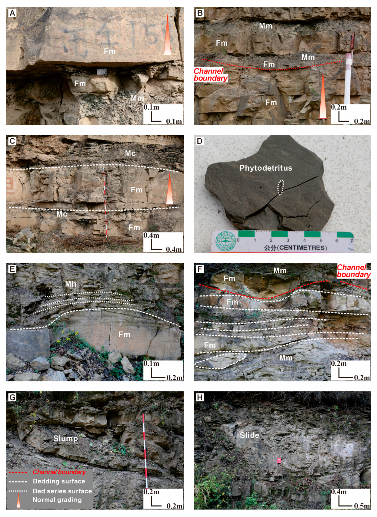
| Fm | Massive Siltstone | Silt | 0.10–2.00 | Lithofacies Fm consists of well-sorted, gray siltstone with a thickness under 2.0 m, interbedded with lithologies Mm and Mh (Figure 6). It is characterized by a fine-grained, homogeneous texture with minimal internal structure. This lithology lacks notable laminations or bioturbation and exhibits a tendency to break into large, block-like fragments due to its cohesive properties (Figure 3). | Lithofacies Fm is formed in high-energy environments with moderate rates of sedimentation. Periodic flooding events facilitate the deposition of fine sediments with minimal reworking. The lithofacies develops rapidly from suspended fine sediments and typically occurs in terminal distributary channels and distal bars [80]. |
| Fr | Current ripple cross-stratified Siltstone | Silt | 0.10–1.00 | The facies is found in dark gray siltstone, characterized by ripple heights of less than 0.5 cm and wavelengths ranging from 2.0 to 4.0 cm (Figure 5G). The laminae exhibit alternating layers of fine-grained silt, distinguished by well-defined ripple features. This is typically observed in (Figure 3). The thickness of individual laminae ranges from 0.1 to 1.0 cm, which contributes to their finely banded appearance. | Lithofacies Fr, which indicates the direction of sediment transport, reflects the movement and accumulation of sandy sediments under unidirectional flow conditions with low hydrodynamic forces. This facies occurs in distal bars and sheet sand deposits [71,80]. |
| Fh | Horizontal bedded Siltstone | Silt | 0.10–0.50 | Lithofacies Fh is developed in dark gray siltstone and interbedded with Mh (Figure 4F and Figure 5H). It is characterized by parallel layers of fine-grained silt with minimal internal structure (Figure 3). These beds exhibit uniform thickness and consistent grain size. The laminae are poorly defined, with thickness ranging from 1.0 to 2.0 mm. | Under stable hydrodynamic conditions, materials precipitate from suspension or solution, forming horizontal bedding composed mainly of fine-grained silt and mud. This lithofacies is common in floodplain settings, representing periods of calm water, where fine sediments settle from suspension. It is found in interdistributary bays [81]. |
| Fs | Deformation structured Siltstone | Silt | 0.40–2.00 | The dark gray, siltstone is characterized by deformation, fragmentation, folding, and fracturing (Figure 6G,H). This lithofacies contains a mixture of mudstone, with a breccia-like appearance and a mudstone sliding surface at its base. Common structural elements include folds, faults, and irregular lamination (Figure 3). The lengths of the sliding and slump bodies range from 4.0 to 5.0 m, with thicknesses between 2.0 and 2.5 m. | Sliding and slumping structures are deformations caused by the movement of unconsolidated sediments on slopes due to gravity. (1) Sliding structures form when sediments move downslope under gravity. (2) Slumping structures occur when liquefaction or fluidization causes silty sand to roll or become suspended, triggered by earthquakes. These structures develop in rapidly deposited sediments in steep environments, particularly within the slope break zone of the prodelta [82,83]. |
| Mm | Massive Mudstone | Mud | 0.10–2.00 | Lithofacies Mm is a dark gray lithology with a homogeneous, fine-grained texture predominantly composed of clay- and silt-sized particles. This rock type is notable for its lack of stratification, internal structure, and bioclasts (Figure 3). It is commonly interbedded with fine sandstone and siltstone (Figure 5A and Figure 6). | This lithofacies indicates a stable depositional environment with low-energy conditions. The absence of distinct bedding planes suggests rapid sediment deposition, often associated with events like flooding or sediment overloading. It is commonly found in interdistributary bays [81]. |
| Mh | Horizontal bedded Mudstone | Mud | 0.10–0.50 | Lithology Mh consists of dark gray mudstone with high organic matter content. The laminae are parallel and straight, with no discernible bedding planes, and exhibit excellent continuity. The laminae thicknesses range from 1.0 to 2.0 mm (Figure 3 and Figure 4F). | It reflects sediment deposition in stable, low-energy environments, typical of low-flow conditions. This lithofacies is commonly found in floodplains, riverbanks, interdistributary bays, and prodelta regions, where fine sediments accumulate in calm water [74,81]. |
| Mc | Carbonaceous Mudstone | Mud | 0.10–1.00 | This lithofacies is dark gray to black, characterized by high organic matter content, imparting a distinctive color and often a greasy texture. It consists of fine-grained clay and silt particles, with visible plant remains (Figure 3). It has an organic carbon content ranging from 10.0% to 15.0% (Figure 5B and Figure 6C). | Lithofacies Mc indicates deposition in low-energy environments that facilitate the preservation of organic matter. It is found in interdistributary bay environments, where fine sediments accumulate without significant disturbance [69]. |
| Mp | Phytodetritus Mudstone | Mud | 0.10–1.00 | Lithofacies Mp is composed of dark gray clay and mud particles mixed with significant amounts of plant debris, resulting in a high organic matter content (Figure 3). Phytodetritus ranges in size from 2.0 to 30.0 cm (Figure 5E and Figure 6D). | This sedimentary environment is characterized by low energy, with plant debris indicating proximity to the lake shore, where mud sediments accumulate. It represents a periodically flooded depositional area within the interdistributary bay of the delta front [84]. |
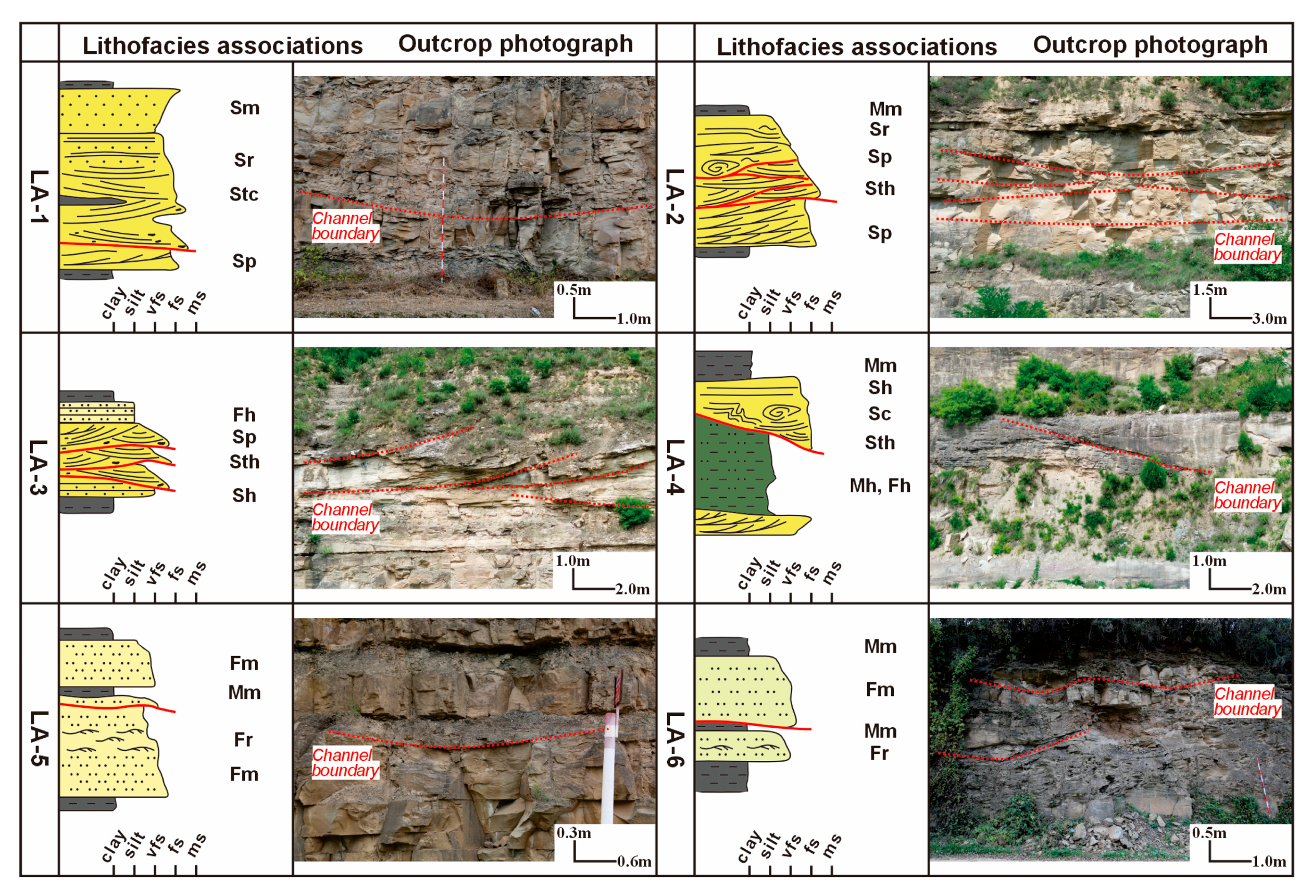
4.2. Lithofacies Associations
4.2.1. LA-1: Major Distributary Channel-Fill Deposits
4.2.2. LA-2: Amalgamated Swinging Distributary Channel-Fill Complexes Deposits
4.2.3. LA-3: Amalgamated Lateral Accretion Distributary Channel-Fill Complex Deposits
4.2.4. LA-4: Interdistributary Bay and Overflow Deposits
4.2.5. LA-5: Distal Bar with Terminal Distributary Channel Erosion-Fill Deposits
4.2.6. LA-6: Terminal Distributary Channel Erosion-Fill Deposits
4.3. Morphology, Fill Patterns, and Facies Zone of Distributary Channels
4.3.1. Type 1: Aggradation Channel with Erosion Base
4.3.2. Type 2: Swinging Channel with Erosion Base
4.3.3. Type 3: Lateral Accretion Channel with Erosion Base
4.3.4. Type 4: Filled Channel with Erosion Base
4.4. The Paleoslope–Channel Morphology Relationship
4.4.1. Width-to-Thickness Ratio
4.4.2. Degree of Symmetry
4.4.3. Migration Frequency
4.4.4. Channel Lithologic Character
4.4.5. Paleoslope Classification
5. Discussion
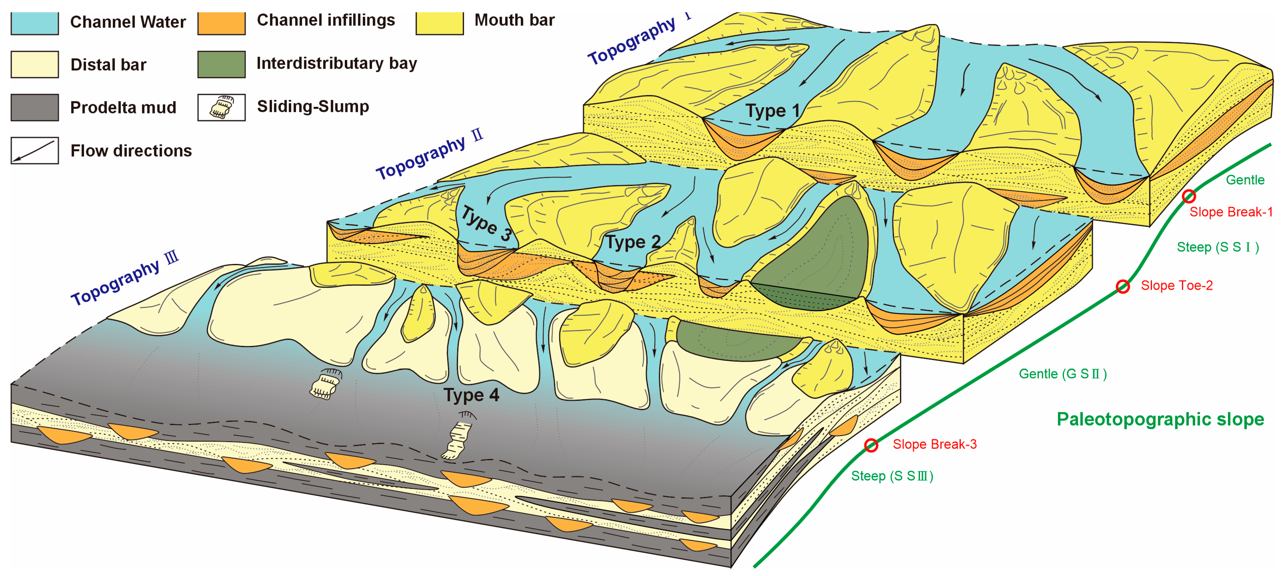
5.1. Facies Zone–Topography Control on Channel
5.1.1. River Mouth to Proximal Delta Front-Topography I Control on Type 1 Channel
5.1.2. Medial Delta Front-Topography II Control on Type 2 and 3 Channels
5.1.3. Distal Delta Front to Slope Break-Topography III Control on Type 4 Channel
5.2. Evolution Patterns of Distributary Channels
5.3. Aggradation Pattern of Channels in Response to Topography
5.4. Implications for Reservoir Prediction
6. Conclusions
Author Contributions
Funding
Data Availability Statement
Acknowledgments
Conflicts of Interest
References
- Liu, L.; Chen, H.; Wen, H.; Xu, W.; Zhong, Y.; Wang, X.; Wang, Z. Facies architecture and sediment infilling processes in intrabasinal slope belts of lacustrine rift basins, Zhanhua Depression, Bohai Bay Basin. Mar. Pet. Geol. 2020, 112, 104089. [Google Scholar] [CrossRef]
- Tye, R.S.; Coleman, J.M. Depositional processes and stratigraphy of fluvially dominated lacustrine deltas; Mississippi delta plain. J. Sediment. Res. 1989, 59, 973–996. [Google Scholar] [CrossRef]
- Alfaro, E.; Holz, M. Seismic geomorphological analysis of deepwater gravity-driven deposits on a slope system of the southern Colombian Caribbean margin. Mar. Pet. Geol. 2014, 57, 294–311. [Google Scholar] [CrossRef]
- Xia, S.; Li, X.; Deng, J.; Luo, D.; Shu, L.; Wang, S.; Wu, P.; Peng, K.; Zhang, X.; Ji, X. Sequence architecture and depositional evolution of the late Palaeogene in southwestern slope of Lufeng Depression, Pearl River Mouth Basin: Responses to tectonic processes and base-level changes. Geol. J. 2020, 55, 1468–1492. [Google Scholar] [CrossRef]
- Wei, Z.; Li, S.; Zhang, T.; Liu, Y.; Yao, Z.; Xu, W.; Li, H. The delta-fluvial evolution of a lacustrine basin with gentle slope and low sedimentation rate: A case study of the Fudong Slope, Junggar Basin, Northwest China. Sediment. Geol. 2023, 453, 106441. [Google Scholar] [CrossRef]
- Baydin, S.S. Formation of Modern Delta Branches on Non-Tidal Rivers with Large Sediment Discharge; United Nations Educational, Scientific and Cultural Organisation: Paris, France, 1970. [Google Scholar]
- Heerden, I.L.V.; Roberts, H.H. Facies development of Atchafalaya Delta, Louisiana: A modern bayhead delta. AAPG Bull. 1988, 72, 439–453. [Google Scholar] [CrossRef]
- Olariu, C.; Bhattacharya, J.P. Terminal distributary channels and delta front architecture of river-dominated delta systems. J. Sediment. Res. 2006, 76, 212–233. [Google Scholar] [CrossRef]
- Axelsson, V. The Laitaure Delta: A study of deltaic morphology and processes. Geogr. Ann. Ser. A Phys. Geogr. 1967, 49, 1–127. [Google Scholar] [CrossRef]
- DuMars, A.J. Distributary Mouth Bar Formation and Channel Bifurcation in the Wax Lake Delta, Atchafalaya Bay, Louisiana. Master’s Thesis, Louisiana State University and Agricultural & Mechanical College, Baton Rouge, LA, USA, 2002. [Google Scholar]
- Bhattacharya, J.P.; Willis, B.J. Lowstand deltas in the Frontier Formation, Powder River Basin, Wyoming: Implications for sequence stratigraphic models. AAPG Bull. 2001, 85, 261–294. [Google Scholar] [CrossRef]
- Overeem, I.; Kroonenberg, S.B.; Veldkamp, A.; Groenesteijn, K.; Rusakov, G.V.; Svitoch, A.A. Small-scale stratigraphy in a large ramp delta: Recent and Holocene sedimentation in the Volga delta, Caspian Sea. Sediment. Geol. 2003, 159, 133–157. [Google Scholar] [CrossRef]
- Olariu, C.; Bhattacharya, J.P.; Xu, X.; Aiken, C.L.; Zeng, X.; Mcmechan, G.A. Integrated Study of Ancient Delta-Front Deposits, Using Outcrop, Ground-Penetrating Radar, and Three-Dimensional Photorealistic Data: Cretaceous Panther Tongue Sandstone, Utah, USA. In River Deltas–Concepts, Models, and Examples; Society for Sedimentary Geology: Claremore, OK, USA, 2005. [Google Scholar] [CrossRef]
- Gilbert, G.K. The Topographic Features of Lake Shores; US Government Printing Office: Washington, DC, USA, 1885. [Google Scholar]
- Albertson, M.L.; Dai, Y.; Jensen, R.A.; Rouse, H. Diffusion of submerged jets. Trans. Am. Soc. Civ. Eng. 1950, 115, 639–664. [Google Scholar] [CrossRef]
- Bates, C.C. Rational theory of delta formation. AAPG Bull. 1953, 37, 2119–2162. [Google Scholar]
- Postma, G. An analysis of the variation in delta architecture. Terra Nova 1990, 2, 124–130. [Google Scholar] [CrossRef]
- Postma, G. Depositional architecture and facies of river and fan deltas: A synthesis. In Coarse-Grained Deltas; Wiley: Hoboken, NJ, USA, 1990; pp. 13–27. [Google Scholar] [CrossRef]
- Nemec, W.; Oti, M.N.; Postma, G. The dynamics of deltaic suspension plumes. In Geology of Deltas; A. A. Balkema: Cape Town, South Africa, 1995; pp. 31–93. [Google Scholar]
- Olariu, C.; Steel, R.J.; Petter, A.L. Delta-front hyperpycnal bed geometry and implications for reservoir modeling: Cretaceous Panther Tongue delta, Book Cliffs, Utah. AAPG Bull. 2010, 94, 819–845. [Google Scholar] [CrossRef]
- Caineng, Z.; Xingyang, Z.; Ping, L.; Lan, W.; Zhong, L.; Liuhong, L. Shallow-lacustrine sand-rich deltaic depositional cycles and sequence stratigraphy of the Upper Triassic Yanchang Formation, Ordos Basin, China. Basin Res. 2010, 22, 108–125. [Google Scholar] [CrossRef]
- Olariu, C.; Bhattacharya, J.P.; Leybourne, M.I.; Boss, S.K.; Stern, R.J. Interplay between river discharge and topography of the basin floor in a hyperpycnal lacustrine delta. Sedimentology 2012, 59, 704–728. [Google Scholar] [CrossRef]
- Dixon, J.F.; Steel, R.J.; Olariu, C. River-dominated, shelf-edge deltas: Delivery of sand across the shelf break in the absence of slope incision. Sedimentology 2012, 59, 1133–1157. [Google Scholar] [CrossRef]
- Martini, I.; Sandrelli, F. Facies analysis of a Pliocene river-dominated deltaic succession (Siena Basin, Italy): Implications for the formation and infilling of terminal distributary channels. Sedimentology 2015, 62, 234–265. [Google Scholar] [CrossRef]
- Coleman, J.M.; Wright, L.D. Modern river deltas: Variability of processes and sand bodies. Geol. Environ. Sci. 1975, 99–149. [Google Scholar]
- Edmonds, D.A.; Slingerland, R.L. Significant effect of sediment cohesion on delta morphology. Nat. Geosci. 2010, 3, 105–109. [Google Scholar] [CrossRef]
- Falcini, F.; Jerolmack, D.J. A potential vorticity theory for the formation of elongate channels in river deltas and lakes. J. Geophys. Res. Earth Surf. 2010, 115, F04038. [Google Scholar] [CrossRef]
- Geleynse, N.; Storms, J.E.; Walstra, D.R.; Jagers, H.A.; Wang, Z.B.; Stive, M.J. Controls on river delta formation; insights from numerical modelling. Earth Planet. Sci. Lett. 2011, 302, 217–226. [Google Scholar] [CrossRef]
- Paola, C.; Twilley, R.R.; Edmonds, D.A.; Kim, W.; Mohrig, D.; Parker, G.; Viparelli, E.; Voller, V.R. Natural processes in delta restoration: Application to the Mississippi Delta. Annu. Rev. Mar. Sci. 2011, 3, 67–91. [Google Scholar] [CrossRef] [PubMed]
- Caldwell, R.L.; Edmonds, D.A. The effects of sediment properties on deltaic processes and morphologies: A numerical modeling study. J. Geophys. Res. Earth Surf. 2014, 119, 961–982. [Google Scholar] [CrossRef]
- Burpee, A.P.; Slingerland, R.L.; Edmonds, D.A.; Parsons, D.; Best, J.; Cederberg, J.; McGuffin, A.; Caldwell, R.; Nijhuis, A.; Royce, J. Grain-size controls on the morphology and internal geometry of river-dominated deltas. J. Sediment. Res. 2015, 85, 699–714. [Google Scholar] [CrossRef]
- Zinke, P.; Olsen, N.; Bogen, J. Three-dimensional numerical modelling of levee depositions in a Scandinavian freshwater delta. Geomorphology 2011, 129, 320–333. [Google Scholar] [CrossRef]
- Yu, X.H.; Li, S.L.; Sun, H.W. Coupling effect of “mass-slope” from source to sink in clastic rock deposition. J. Palaeogeogr. Chin. Ed. 2022, 24, 1037–1057. [Google Scholar]
- Syvitski, J.P.M.; Kettner, A.J.; Correggiari, A.; Nelson, B.W. Distributary channels and their impact on sediment dispersal. Mar. Geol. 2005, 222–223, 75–94. [Google Scholar] [CrossRef]
- Anees, A.; Zhang, H.; Ashraf, U.; Wang, R.; Liu, K.; Mangi, H.N.; Jiang, R.; Zhang, X.; Liu, Q.; Tan, S.; et al. Identification of favorable zones of gas accumulation via fault distribution and sedimentary facies: Insights from Hangjinqi area, northern Ordos Basin. Front. Earth Sci. 2022, 9, 822670. [Google Scholar] [CrossRef]
- Muto, T.; Steel, R.J. Autostepping during the transgressive growth of deltas: Results from flume experiments. Geology 2001, 29, 771–774. [Google Scholar] [CrossRef]
- Holbrook, J.; Scott, R.W.; Oboh-Ikuenobe, F.E. Base-level buffers and buttresses: A model for upstream versus downstream control on fluvial geometry and architecture within sequences. J. Sediment. Res. 2006, 76, 162–174. [Google Scholar] [CrossRef]
- Gibling, M.R. Width and thickness of fluvial channel bodies and valley fills in the geological record: A literature compilation and classification. J. Sediment. Res. 2006, 76, 731–770. [Google Scholar] [CrossRef]
- Paola, C.; Heller, P.L.; Angevine, C.L. The large-scale dynamics of grain-size variation in alluvial basins. Basin Res. 1992, 4, 73–90. [Google Scholar] [CrossRef]
- Miall, A.D. The Geology of Stratigraphic Sequences; Springer Science & Business Media: Berlin/Heidelberg, Germany, 2010. [Google Scholar]
- Miall, A.D. The Geology of Fluvial Deposits: Sedimentary Facies, Basin Analysis, and Petroleum Geology; Springer: Berlin/Heidelberg, Germany, 2013. [Google Scholar]
- He, M.; Zhuo, H.; Chen, W.; Wang, Y.; Du, J.; Liu, L.; Wang, L.; Wan, H. Sequence stratigraphy and depositional architecture of the Pearl River Delta system, northern South China Sea: An interactive response to sea level, tectonics and paleoceanography. Mar. Pet. Geol. 2017, 84, 76–101. [Google Scholar] [CrossRef]
- Xu, S.; Hao, F.; Xu, C.; Zou, H.; Gao, B. Seismic geomorphology and sedimentology of a fluvial-dominated delta: Implications for the Neogene reservoirs, offshore Bohai Bay Basin, China. AAPG Bull. 2019, 103, 2399–2420. [Google Scholar] [CrossRef]
- Bhattacharya, J.P.; Giosan, L. Wave-influenced deltas: Geomorphological implications for facies reconstruction. Sedimentology 2003, 50, 187–210. [Google Scholar] [CrossRef]
- Anees, A.; Shi, W.; Ashraf, U.; Xu, Q. Channel identification using 3D seismic attributes and well logging in lower Shihezi Formation of Hangjinqi area, northern Ordos Basin, China. J. Appl. Geophys. 2019, 163, 139–150. [Google Scholar] [CrossRef]
- Anees, A.; Zhang, H.; Ashraf, U.; Wang, R.; Liu, K.; Abbas, A.; Ullah, Z.; Zhang, X.; Duan, L.; Liu, F.; et al. Sedimentary facies controls for reservoir quality prediction of lower shihezi member-1 of the Hangjinqi area, Ordos Basin. Miner 2022, 12, 126. [Google Scholar] [CrossRef]
- Zhang, C.M.; Yin, T.J.; Zhu, Y.J.; Ke, L.M. Shallow-Water Deltas and Models. Acta Sedimentol. Sin. 2010, 28, 92–103. [Google Scholar]
- Guo, Y.Q.; Li, W.H.; Guo, B.C.; Zhang, Q.; Chen, Q.; Wang, R.G.; Liu, X.; Ma, Y.; Li, Z.C.; Zhang, M.T.; et al. Sedimentary system and paleogeographic evolution of Ordos Basin. J. Palaeogeogr. Chin. Ed. 2019, 21, 293–320. [Google Scholar]
- Xian, B.Z.; Wang, J.H.; Gong, C.L.; Yin, Y.; Chao, C.Z.; Liu, J.P.; Zhang, G.D.; Yan, Q. Classification and sedimentary characteristics of lacustrine hyperpycnal channels; Triassic outcrops in the south Ordos Basin, central China. Sediment. Geol. 2018, 368, 68–82. [Google Scholar] [CrossRef]
- Liu, S.; Yang, S. Upper Triassic—Jurassic sequence stratigraphy and its structural controls in the western Ordos Basin, China. Basin Res. 2000, 12, 1–18. [Google Scholar] [CrossRef]
- Chen, Q.; Li, W.; Gao, Y.; Guo, Y.; Feng, J.; Zhang, D.; Cao, H.; Liang, J. The deep-lake deposit in the Upper Triassic Yanchang Formation in Ordos Basin, China and its significance for oil-gas accumulation. Sci. China Ser. D Earth Sci. 2007, 50, 47–58. [Google Scholar] [CrossRef]
- Zou, C.N.; Zhao, W.Z.; Zhang, X.Y.; Luo, P.; Wang, L.; Liu, L.H.; Xue, S.H.; Yuan, X.J.; Zhu, R.K.; Tao, S.Z. Formation and distribution of shallow-water deltas and central-basin sandbodies in large open depression lake basins. Acta Geol. Sin. 2008, 82, 813–825. [Google Scholar]
- Lai, J.; Wang, G.W.; Ran, Y.; Zhou, Z.L.; Cui, Y.F. Impact of diagenesis on the reservoir quality of tight oil sandstones: The case of Upper Triassic Yanchang Formation Chang 7 oil layers in Ordos Basin, China. J. Pet. Sci. Eng. 2016, 145, 54–65. [Google Scholar] [CrossRef]
- Ren, Y.L.; Zhao, J.F.; Chen, J.Y.; Guan, X.; Song, J.G. Sedimentary characteristics and sand body Architecture of shallow Delta Front in Ordos Basin: A case study of Chang 9 Member in Shiwanghe Section in Yichuan. Xinjiang Pet. Geol. 2022, 43, 310–319. [Google Scholar]
- Zou, C.N.; Wang, L.; Li, Y.; Tao, S.Z.; Hou, L.H. Deep-lacustrine transformation of sandy debrites into turbidites, Upper Triassic, Central China. Sediment. Geol. 2012, 265–266, 143–155. [Google Scholar] [CrossRef]
- Yang, R.C.; Jin, Z.J.; Van Loon, A.T.; Han, Z.Z.; Fan, A.P. Climatic and tectonic controls of lacustrine hyperpycnite origination in the Late Triassic Ordos Basin, central China: Implications for unconventional petroleum development. AAPG Bull. 2017, 101, 95–117. [Google Scholar] [CrossRef]
- Xu, Q.H.; Shi, W.Z.; Xie, X.Y.; Manger, W.; McGuire, P.; Zhang, X.M.; Wang, R.; Xu, Z. Deep-lacustrine sandy debrites and turbidites in the lower Triassic Yanchang Formation, southeast Ordos Basin, central China: Facies distribution and reservoir quality. Mar. Pet. Geol. 2016, 77, 1095–1107. [Google Scholar] [CrossRef]
- Folk, R.L. Petrology of Sedimentary Rocks; Hemphill Publishing Company: Austin, TX, USA, 1980. [Google Scholar]
- Wentworth, C.K. A Scale of Grade and Class Terms for Clastic Sediments. J. Geol. 1922, 30, 377–392. [Google Scholar] [CrossRef]
- Miall, A.D. A review of the braided-river depositional environment. Earth-Sci. Rev. 1977, 13, 1–62. [Google Scholar] [CrossRef]
- Cotter, E.; Miall, A.D. Fluvial sedimentology. Can. Soc. Pet. Geol. 1978, 5, 361–383. [Google Scholar]
- Miall, A.D. Reservoir heterogeneities in fluvial sandstones: Lessons from outcrop studies. AAPG Bull. 1988, 72, 682–697. [Google Scholar]
- Bridge, J.S. Description and interpretation of fluvial deposits: A critical perspective. Sedimentology 1993, 40, 801–810. [Google Scholar] [CrossRef]
- Nichols, G. Sedimentary Basins. Evolution, Facies, and Sediment Budget. Sediment. Geol. 2001, 143, 729–733. [Google Scholar]
- Galloway, W.E. Process framework for describing the morphologic and stratigraphic evolution of deltaic depositional systems. AAPG Bull. 1975, 7, 87–98. [Google Scholar]
- Guan, X.; Wu, J.; Wei, L.; Zhao, J.; Feng, G.; Li, Y. Meandering River Deposit and Sand Body Architecture in Qigu Formation of Jiangong Coal Mine Section in the Southern Margin of Junggar Basin. Xinjiang Pet. Geol. 2019, 40, 290–297. [Google Scholar]
- Celis, S.A.; García-García, F.; Rodríguez-Tovar, F.J.; Giraldo-Villegas, C.A.; Pardo-Trujillo, A. Coarse-grained submarine channels: From confined to unconfined flows in the Colombian Caribbean (late Eocene). Sediment. Geol. 2024, 459, 106550. [Google Scholar] [CrossRef]
- Lai, J.; Wang, G.; Fan, Z.; Chen, J.; Wang, S.; Fan, X. Sedimentary characterization of a braided delta using well logs: The Upper Triassic Xujiahe Formation in Central Sichuan Basin, China. J. Pet. Sci. Eng. 2017, 154, 172–193. [Google Scholar] [CrossRef]
- Pang, J.; Colombera, L.; Mountney, N.P.; Guo, J.; Yang, K.; Li, W. Mapping palaeoshorelines of river-dominated deltas in lacustrine ramp settings: Application of sedimentological analyses to the Triassic Yanchang Formation (Ordos Basin, China). Mar. Pet. Geol. 2024, 164, 106797. [Google Scholar] [CrossRef]
- Turner, B.R.; Tester, G.N. The Table Rocks Sandstone: A fluvial, friction-dominated lobate mouth bar sandbody in the Westphalian B Coal Measures, NE England. Sediment. Geol. 2006, 190, 97–119. [Google Scholar] [CrossRef]
- Winsemann, J.; Lang, J.; Fedele, J.J.; Zavala, C.; Hoyal, D.C.J.D. Re-examining models of shallow-water deltas: Insights from tank experiments and field examples. Sediment. Geol. 2021, 421, 105962. [Google Scholar] [CrossRef]
- Magalhães, A.J.C.; Scherer, C.M.S.; Gabaglia, G.P.R.; Catuneanu, O. Mesoproterozoic delta systems of the Ac¸ uruá Formation, Chapada Diamantina, Brazil. Precambrian Res. 2015, 257, 1–21. [Google Scholar] [CrossRef]
- Lang, J.; Brandes, C.; Winsemann, J. Erosion and deposition by supercritical density flows during channel avulsion and backfilling: Field examples from coarse-grained deepwater channel-levée complexes (Sandino Forearc Basin, southern Central America). Sediment. Geol. 2017, 349, 79–102. [Google Scholar] [CrossRef]
- Deng, Q.; Hu, M.; Su, S.; Chen, W.; Shen, J.; Kane, O.I.; Cai, Q.; Hu, Z. Factors controlling reservoir quality of a retreating delta-front in shallow-water lacustrine in the Songliao Basin, Northeast China. J. Pet. Sci. Eng. 2022, 216, 110773. [Google Scholar] [CrossRef]
- Silva, F.A.B.D.; França, M.C.; Cohen, M.C.L.; Pessenda, L.C.R.; Mayle, F.E.; Fontes, N.A.; Lorente, F.L.; Junior, A.Á.B.; Piccolo, M.D.C.; Bendassolli, J.A.; et al. Late Holocene mangrove dynamics of the Doce River delta, southeastern Brazil: Implications for the understanding of mangrove resilience to sea-level changes and channel dynamics. Palaeogeogr. Palaeoclimatol. Palaeoecol. 2022, 600, 111055. [Google Scholar] [CrossRef]
- Degeai, J.; Joseph, C.; Salel, T.; Giaime, M.; Rovira, N.; Piquès, G. Relationships between channelization, sedimentation and sea level in the deltaic environment of the ancient harbor of Lattara, southern France. Mar. Geol. 2024, 476, 107384. [Google Scholar] [CrossRef]
- Peng, Y.; Steel, R.J.; Olariu, C.; Li, S. Rapid subsidence and preservation of fluvial signals in an otherwise wave-reworked delta front succession: Early-mid Pliocene Orinoco continental-margin growth, SE Trinidad. Sediment. Geol. 2020, 395, 105555. [Google Scholar] [CrossRef]
- Chen, S.; Steel, R.J.; Olariu, C. Chapter 7—Palaeo-Orinoco (Pliocene) Channels on the Tide-Dominated Morne L’Enfer Delta Lobes and Estuaries, SW Trinidad. In Developments in Sedimentology; Springer: Berlin/Heidelberg, Germany, 2015; Volume 68, pp. 227–281. [Google Scholar] [CrossRef]
- Moyano-Paz, D.; Isla, M.F.; MacEachern, J.A.; Richiano, S.; Gómez-Dacal, A.R.; Varela, A.N.; Poiré, D.G. Evolution of an aggradational wave-dominated delta: Sediment balance and animal-substrate dynamics (Upper Cretaceous La Anita Formation, Southern Patagonia). Sediment. Geol. 2022, 437, 106193. [Google Scholar] [CrossRef]
- Liu, C.; Jiang, Z.; Zhou, X.; Duan, Y.; Lei, H.; Wang, X.; Quaye, J.A. Paleocene storm-related event beds in the Gaoyou Sag of the Subei Basin, eastern China: A new interpretation for these deep lacustrine sandstones. Mar. Pet. Geol. 2021, 124, 104850. [Google Scholar] [CrossRef]
- Shawwa, N.A.; McLoughlin-Coleman, T.R.; Babechuk, M.G.; Rainbird, R.H. Paleoproterozoic (Huronian) valley-controlled deglacial-fluvial sedimentation, northern Cobalt Basin, Ontario, Canada. Sediment. Geol. 2023, 455, 106421. [Google Scholar] [CrossRef]
- Kim, J.W.; Chough, S.K. A gravel lobe deposit in the prodelta of the Doumsan fan delta (Miocene), SE Korea. Sediment. Geol. 2000, 130, 183–203. [Google Scholar] [CrossRef]
- Gibert, L.; Galdeano, C.S.D.; Alfaro, P.; Scott, G.; Garrido, A.C.L. Seismic-induced slump in Early Pleistocene deltaic deposits of the Baza Basin (SE Spain). Sediment. Geol. 2005, 179, 279–294. [Google Scholar] [CrossRef]
- Arregui, M.G.; Buatois, L.A.; Rodriguez, E. Shrimps and leaves: Phytodetrital pulses and bioturbation in deposits of a river-dominated delta (Middle Jurassic Lajas Formation, Neuquén Basin, Argentina). Palaeogeogr. Palaeoclimatol. Palaeoecol. 2019, 516, 179–189. [Google Scholar] [CrossRef]
- van Cappelle, M.; Ravnås, R.; Hampson, G.J.; Johnson, H.D. Depositional evolution of a progradational to aggradational, mixed-influenced deltaic succession: Jurassic Tofte and Ile formations, southern Halten Terrace, offshore Norway. Mar. Pet. Geol. 2017, 80, 1–22. [Google Scholar] [CrossRef]
- Bayet-Goll, A.; de Carvalho, C.N. Architectural evolution of a mixed-influenced deltaic succession: Lower-to-Middle Ordovician Armorican Quartzite in the southwest Central Iberian Zone, Penha Garcia Formation (Portugal). Int. J. Earth Sci. 2020, 109, 2495–2526. [Google Scholar] [CrossRef]
- Obodoefuna, D.C.; Fan, D.; Guo, X.; Li, B. Highly accelerated siltation of abandoned distributary channel in the Yangtze Delta under everchanging social-ecological dynamics. Mar. Geol. 2020, 429, 106331. [Google Scholar] [CrossRef]
- Zhang, L.; Bao, Z.; Dou, L.; Xu, Q. Diagenetic alterations related to sedimentary architecture of deltaic distributary channels in red beds of the Cretaceous Yaojia Formation, Songliao Basin. J. Pet. Sci. Eng. 2021, 203, 108564. [Google Scholar] [CrossRef]
- Liu, Y.; Yu, X.; Li, S.; Du, W.; Li, M.; Li, S. Characteristics and Evolution of Sedimentary Microfacies of Chang 6—4+5 Layer in the Northern Area of Western Mahuang Mountain. Earth Sci. Front. 2009, 16, 277–286. [Google Scholar] [CrossRef]
- Petter, A.L.; Steel, R.J. Hyperpycnal flow variability and slope organization on an Eocene shelf margin, Central Basin, Spitsbergen. AAPG Bull. 2006, 90, 1451–1472. [Google Scholar] [CrossRef]
- Edmonds, D.; Chadwick, A.J.; Lamb, M.P.; Lorenzo-Trueba, J.; Murray, B.; Nardin, W.; Salter, G.; Shaw, J.B. Morphodynamic modeling of river-dominated deltas: A review and future perspectives. Authorea Preprint 2022. [Google Scholar] [CrossRef]
- Zeng, Z.; Zhu, H.; Yang, X.; Zeng, H.; Hu, X.; Xia, C. The Pangaea Megamonsoon records: Evidence from the Triassic Mungaroo Formation, Northwest Shelf of Australia. Gondwana Res. 2019, 69, 1–24. [Google Scholar] [CrossRef]
- Yin, S.; Hu, Z.; Ren, X.; Wu, X.; Chen, Y.; Zheng, L.; Jiang, Z. Reservoir architecture patterns of sandy gravel braided distributary channel A case study of Triassic Upper Karamay Formation, Xinjiang oilfield. Petroleum 2016, 2, 117–129. [Google Scholar] [CrossRef]
- Wang, H.; Guo, Y.; Huang, Y.; Yu, C.; Huo, Z.; Li, X.; Chen, X. Morphologies, patterns, and filling architectures at the confluence zones of the cretaceous shallow-water delta in the Songliao Basin, NE China. J. Asian Earth Sci. 2023, 254, 105758. [Google Scholar] [CrossRef]
- Miall, A.D. Architectural-element analysis: A new method of facies analysis applied to fluvial deposits. Earth-Sci. Rev. 1985, 22, 261–308. [Google Scholar] [CrossRef]
- Bridge, J.S.; Tye, R.S. Interpreting the dimensions of ancient fluvial channel bars, channels, and channel belts from wireline-logs and cores. AAPG Bull. 2000, 84, 1205–1228. [Google Scholar] [CrossRef]
- Villegas, P.M.; Umazano, A.M.; Melchor, R.N.; Kataoka, K. Soft-sediment deformation structures in gravelly fluvial deposits: A record of Cretaceous seismic activity in Patagonia? J. S Am. Earth Sci. 2019, 90, 325–337. [Google Scholar] [CrossRef]
- Knaust, D.; Hoth, S. Bay-head deltas as hydrocarbon reservoirs: The Middle Jurassic Hugin Formation in Block 15/3 of the South Viking Graben, Norway. Mar. Pet. Geol. 2021, 126, 104841. [Google Scholar] [CrossRef]
- Ortiz, S.S.; Lowe, D.G. Stratal evolution and provenance of a precambrian delta in a tectonically active terrane: The lower Signal Hill Group, Avalon Zone, Newfoundland. Precambrian Res. 2024, 401, 107274. [Google Scholar] [CrossRef]
- Li, S.; Ma, Y.Z.; Yu, X.; Jiang, P.; Li, M.; Li, M. Change of deltaic depositional environment and its impacts on reservoir properties—A braided delta in South China Sea. Mar. Pet. Geol. 2014, 58, 760–775. [Google Scholar] [CrossRef]
- Celis, S.A.; Rodríguez-Tovar, F.J.; Pardo-Trujillo, A.; García-García, F.; Giraldo-Villegas, C.A.; Gallego, F.; Plata, Á.; Trejos-Tamayo, R.; Vallejo-Hincapié, F.; Cardona, F.J. Deciphering influencing processes in a tropical delta system (middle-late Eocene to Early Miocene, Colombian Caribbean): Signals from a well-core integrative sedimentological, ichnological, and micropaleontological analysis. J. S. Am. Earth Sci. 2023, 127, 104368. [Google Scholar] [CrossRef]
- Abdel-Fattah, Z.A. Facies transition and depositional architecture of the Late Eocene tide-dominated delta in northern coast of Birket Qarun, Fayum, Egypt. J. Afr. Earth Sci. 2016, 119, 185–203. [Google Scholar] [CrossRef]
- Rossi, V.; Barbieri, G.; Vaiani, S.C.; Amorosi, A. Benthic foraminifers from Holocene subaqueous deltas of the Western Mediterranean: Stratigraphic implications and palaeoenvironmental significance of the biofacies. Mar. Geol. 2021, 442, 106632. [Google Scholar] [CrossRef]
- Zhang, Y.; Shi, Z.; Li, J.; Wang, J.; Yang, B.; Jiang, J. The influence of water level changes on sand bodies at river-dominated delta fronts: The Gubei Sag, Bohai Bay Basin. Pet. Sci. 2022, 19, 58–73. [Google Scholar] [CrossRef]
- Mancuso, A.C. Taphonomic analysis in lacustrine environments: Two different contexts for Triassic lake paleofloras from Western Gondwana (Argentina). Sediment. Geol. 2009, 222, 149–159. [Google Scholar] [CrossRef]
- Liu, H.; Qiu, Z.; Xu, L.; Wang, F.; Tong, Q.; Lin, J.; Yin, S.; Wang, W. Distribution of shallow water delta sand bodies and the genesis of thick layer sand bodies of the Triassic Yanchang Formation, Longdong Area, Ordos Basin. Pet. Explor. Dev. 2021, 48, 123–135. [Google Scholar] [CrossRef]
- Nyman, S.L.; Gani, M.R.; Bhattacharya, J.P.; Lee, K. Origin and distribution of calcite concretions in Cretaceous Wall Creek Member, Wyoming: Reservoir-quality implication for shallow-marine deltaic strata. Cretac. Res. 2014, 48, 139–152. [Google Scholar] [CrossRef]
- Wang, K.; Wu, G.; Liang, B.; Shi, B.; Li, H. Linking marsh sustainability to event-based sedimentary processes: Impulsive river floods initiated lateral erosion of deltaic marshes. Coast. Eng. 2024, 190, 104515. [Google Scholar] [CrossRef]
- Irastorza, A.; Zavala, C.; Campetella, D.M.; Turienzo, M.; Sánchez, N.; Durán, T.; Peñalva, G. Origin and evolution of shallowing-upward clastic successions: A case example from the Lower Cretaceous Agrio Formation, Neuqu’en Basin, Argentina. J. S. Am. Earth Sci. 2024, 137, 104855. [Google Scholar] [CrossRef]
- Shanmugam, G. New perspectives on deep-water sandstones: Implications. Pet. Explor. Dev. 2013, 40, 316–324. [Google Scholar] [CrossRef]
- Lu, Q.Q.; Xin, H.G.; Wang, L.; Luo, S.S.; Dan, W.D. Sedimentary types, characteristics and model of lacustrine fine-grained gravity flow in the Member 7 of Trassic Yanchang Formation in Ningxian area, Ordos Basin. J. Palaeogeogr. 2023, 25, 823–840. [Google Scholar]
- Yang, R.C.; He, Z.L.; Qiu, G.Q.; Jin, Z.J.; Sun, D.S.; Jin, X.H. A Late Triassic gravity flow depositional system in the southern Ordos Basin. Pet. Explor. Dev. 2014, 41, 724–733. [Google Scholar] [CrossRef]
- Yang, T.; Cao, Y.; Wang, Y.; Zhang, S. Types, sedimentary characteristics and genetic mechanisms of deep-water gravity flows: A case study of the middle submember in Member 3 of Shahejie Formation in Jiyang depression. Acta Pet. Sin. 2015, 36, 1048. [Google Scholar]
- Niu, X.; Yang, T.; Cao, Y.; Li, S.; Zhou, X.; Xi, K.; Dodd, T.J.H. Characteristics and formation mechanisms of gravity-flow deposits in a lacustrine depression basin: Examples from the Late Triassic Chang 7 oil member of the Yanchang Formation, Ordos Basin, Central China. Mar. Pet. Geol. 2023, 148, 106048. [Google Scholar] [CrossRef]
- Bozetti, G.; Li, X.; Yang, Z.; Liu, H.; Huang, J.; Li, Z.; Xu, J. New insights into deep-lacustrine architectural elements: Examples from the upper Triassic Yanchang Formation, Ordos basin. J. Asian Earth Sci. 2023, 241, 105431. [Google Scholar] [CrossRef]
- Sun, Z.; Bai, Q.; Ren, H.; Yan, K.; Gao, L.; Wei, L. Quantitative evaluation of morphological characteristics of thin sand body: Taking the deltaic distributary channel sand body as an example in Shengtuo oil field of Dongying sag, east of Bohai Bay Basin. J. Pet. Sci. Eng. 2021, 205, 108749. [Google Scholar] [CrossRef]
- Allison, M.A.; Weathers, H.D.; Meselhe, E.A. Bottom morphology in the Song Hau distributary channel, Mekong River Delta, Vietnam. Cont. Shelf Res. 2017, 147, 51–61. [Google Scholar] [CrossRef]
- Graves, B.P.; Ralph, T.J.; Morgan, A.M. Channel breakdown and avulsion in arroyos feeding the Little Colorado River, Arizona, USA. Geomorphology 2025, 468, 109501. [Google Scholar] [CrossRef]
- Mukherjee, S.; Ansari, K.; Raha, A.; Biswas, M.; Mazumder, S. Tectonics of cauvery basin (India) in onshore and offshore portions. Mar. Pet. Geol. 2025, 171, 107142. [Google Scholar] [CrossRef]
- Bouchakour, M.; Zhao, X.; Ge, J.; Miclăuș, C.; Yang, B. Evolution of submarine channel morphology in intra-slope mini-basins: 3D-seismic interpretation from offshore Niger delta. Mar. Pet. Geol. 2022, 146, 105912. [Google Scholar] [CrossRef]
- Parker, G. Self-formed straight rivers with equilibrium banks and mobile bed. Part 2. The gravel river. J. Fluid. Mech. 1978, 89, 127–146. [Google Scholar] [CrossRef]
- Nanson, G.C.; Croke, J.C. A genetic classification of floodplains. Geomorphology 1992, 4, 459–486. [Google Scholar] [CrossRef]
- Hooke, J. River meander behaviour and instability: A framework for analysis. Trans. Inst. Br. Geogr. 2003, 28, 238–253. [Google Scholar] [CrossRef]
- Wright, L.D.; Coleman, J.M.; Thom, B.G. Processes of channel development in a high-tide-range environment: Cambridge Gulf-Ord River Delta, Western Australia. J. Geol. 1973, 81, 15–41. [Google Scholar] [CrossRef]
- Thom, B.G.; Wright, L.D.; Coleman, J.M. Mangrove Ecology and Deltaic-Estuarine Geomorphology: Cambridge Gulf-Ord River, Western Australia. J. Ecol. 1975, 63, 203–232. [Google Scholar] [CrossRef]
- Anees, A.; Zhang, H.; Ashraf, U.; Wang, R.; Thanh, H.V.; Radwan, A.E.; Ullah, J.; Abbasi, G.R.; Iqbal, I.; Ali, N. Sand-ratio distribution in an unconventional tight sandstone reservoir of Hangjinqi area, Ordos Basin: Acoustic impedance inversion-based reservoir quality prediction. Front. Earth Sci. 2022, 10, 1018105. [Google Scholar] [CrossRef]
- Manshor, N.A.; Hassan, M.H.A.; Madon, M. Tidally-influenced fluvial channel systems from the Miocene Malay Basin, Malaysia: Evidence from core facies and seismic geomorphological analyses. Mar. Pet. Geol. 2022, 135, 105384. [Google Scholar] [CrossRef]
- Farrell, K.M. Geomorphology, facies architecture, and high-resolution, non-marine sequence stratigraphy in avulsion deposits, Cumberland Marshes, Saskatchewan. Sediment. Geol. 2001, 139, 93–150. [Google Scholar] [CrossRef]
- Zăinescu, F.; Vespremeanu-Stroe, A.; Anthony, E.; Tătui, F.; Preoteasa, L.; Mateescu, R. Flood deposition and storm removal of sediments in front of a deltaic wave-influenced river mouth. Mar. Geol. 2019, 417, 106015. [Google Scholar] [CrossRef]
- Peterson, C.D.; Pettit, D.J.; Kingen, K.; Vanderburgh, S.; Rosenfeld, C. Catastrophic beach sand losses due to erosion from predicted future sea level rise (0.5–1.0 m), based on increasing submarine accommodation spaces in the high-wave-energy coast of the Pacific Northwest, Washington, Oregon, and Northern California, USA. Mar. Geol. 2021, 439, 106555. [Google Scholar] [CrossRef]
- Levine, E.R.; Goodman, L.; O’Donnell, J. Turbulence in coastal fronts near the mouths of Block Island and Long Island Sounds. J. Mar. Syst. 2009, 78, 476–488. [Google Scholar] [CrossRef]
- Nota, P.J.; Zhang, X.; Liu, H.; Mubikirwa, H.; Majid, A. Effects of upstream and downstream boundary conditions on lacustrine shallow-water delta morphologies: A numerical modeling approach. Mar. Pet. Geol. 2024, 167, 106966. [Google Scholar] [CrossRef]
- Anell, I. The quintessential s-shape in sedimentology: A review on the formation and controls of clinoform shape. Earth-Sci. Rev. 2024, 254, 104821. [Google Scholar] [CrossRef]
- Guo, L.; Zhu, C.; Xie, W.; Xu, F.; Wu, H.; Wan, Y.; Wang, Z.; Zhang, W.; Shen, J.; Wang, Z.; et al. Changjiang Delta in the Anthropocene: Multi-scale hydro-morphodynamics and management challenges. Earth-Sci. Rev. 2021, 223, 103850. [Google Scholar] [CrossRef]
- Dou, L.; Wang, X.; Liu, Y.; Hou, J.; Zhang, L.; Liao, S.; Li, H.; Lai, H.; Liu, D.; Sun, P. River mouth jet plume related deposition in lacustrine shoal-water deltas: Implications for reservoir characterization in lacustrine basins. J. Pet. Sci. Eng. 2022, 219, 111011. [Google Scholar] [CrossRef]
- Rouby, D.; Nalpas, T.; Jermannaud, P.; Robin, C.; Guillocheau, F.; Raillard, S. Gravity driven deformation controlled by the migration of the delta front: The Plio-Pleistocene of the Eastern Niger Delta. Tectonophysics 2011, 513, 54–67. [Google Scholar] [CrossRef]
- Tang, J.; Wu, H.; Xing, F.; Zhang, F.; Tang, B.; Li, G.; Wang, Y. Formation and transport of fluid mud triggered by typhoon events in front of the subaqueous Changjiang Delta. Mar. Geol. 2023, 460, 107052. [Google Scholar] [CrossRef]
- Wu, J.E.; McClay, K.; Frankowicz, E. Niger Delta gravity-driven deformation above the relict Chain and Charcot oceanic fracture zones, Gulf of Guinea: Insights from analogue models. Mar. Pet. Geol. 2015, 65, 43–62. [Google Scholar] [CrossRef]
- Zhu, X.; Zeng, H.; Li, S.; Dong, Y.; Zhu, S.; Zhao, D.; Huang, W. Sedimentary characteristics and seismic geomorphologic responses of a shallow-water delta in the Qingshankou Formation from the Songliao Basin, China. Mar. Pet. Geol. 2017, 79, 131–148. [Google Scholar] [CrossRef]
- Winsemann, J.; Hartmann, T.; Lang, J.; Fälber, R.; Lauer, T. Depositional architecture and aggradation rates of sand-rich, supercritical alluvial fans: Control by autogenic processes or high-frequency climatic oscillations? Sediment. Geol. 2022, 440, 106238. [Google Scholar] [CrossRef]
- Fu, C.; Huang, W.; Li, S.; Chen, H. The spatial discrepancy of Miocene transgression and its corresponding channel transformation pattern: A case study of the carabobo region in the northeast Venezuela basin. J. S. Am. Earth Sci. 2019, 89, 347–365. [Google Scholar] [CrossRef]
- Maloney, J.M.; Bentley, S.J.; Xu, K.; Obelcz, J.; Georgiou, I.Y.; Miner, M.D. Mississippi River subaqueous delta is entering a stage of retrogradation. Mar. Geol. 2018, 400, 12–23. [Google Scholar] [CrossRef]
- Korus, J.T.; Fielding, C.R. Asymmetry in Holocene river deltas: Patterns, controls, and stratigraphic effects. Earth-Sci. Rev. 2015, 150, 219–242. [Google Scholar] [CrossRef]
- Allison, M.A.; Khan, S.R.; Goodbred, S.L.; Kuehl, S.A. Stratigraphic evolution of the late Holocene Ganges—Brahmaputra lower delta plain. Sediment. Geol. 2003, 155, 317–342. [Google Scholar] [CrossRef]
- George, C.F.; Macdonald, D.I.M.; Spagnolo, M. Deltaic sedimentary environments in the Niger Delta, Nigeria. J. Afr. Earth Sci. 2019, 160, 103592. [Google Scholar] [CrossRef]
- Plotzki, A.; May, J.H.; Preusser, F.; Roesti, B.; Denier, S.; Lombardo, U.; Veit, H. Geomorphology and evolution of the late Pleistocene to Holocene fluvial system in the south-eastern Llanos de Moxos, Bolivian Amazon. Catena 2015, 127, 102–115. [Google Scholar] [CrossRef]
- Mahrez, H.B.; Márton, P.; Márton, B.; Szőnyi, J.M.; Kovács, J.; Sztanó, O. Hydrostratigraphic decomposition of fluvio-deltaic sediments inferred from seismic geomorphology and geophysical well logs in the Pannonian Basin, Hungary. Glob. Planet. Change 2023, 230, 104285. [Google Scholar] [CrossRef]
- Fielding, C.R.; Ashworth, P.J.; Best, J.L.; Prokocki, E.W.; Sambrook Smith, G.H. Tributary, distributary and other fluvial patterns: What really represents the norm in the continental rock record? Sediment. Geol. 2012, 261–262, 15–32. [Google Scholar] [CrossRef]


| Lithofacies Associations | Brief Description | Thickness Range (m) | Component Lithofacies | Environmental Interpretation |
|---|---|---|---|---|
| LA-1 | Channelized medium to fine-grained concentric cross-stratified sandstone | 2.0–3.0 | Stc-Sr (dominant); Sp, Sm (subordinated) | River mouth to proximal delta front, major distributary channel, mouth bar setting |
| LA-2 | Multilayered medium to fine-grained heterocentric cross-stratified sandstone with subordinated massive mudstone | 5.0–6.0 | Sth-Sp-Sr (dominant); Sp, Mm (subordinated) | Medial delta front, swinging distributary channel, mouth bar setting |
| LA-3 | Multilayered heterocentric trough cross-stratified sandstone | 5.0–6.0 | Sth-Sp (dominant); Sh, Fh (subordinated) | Medial delta front, lateral accretion distributary channel, mouth bar setting |
| LA-4 | Horizontal bedded mudstone and siltstone with subordinated channelized sandstone | 4.0–5.0 | Fh, Mh, Mm (dominant); Sth-Sc-Sh (subordinated) | Medial delta front, interdistributary bay, overflow deposits setting |
| LA-5 | Current ripple cross-stratified siltstone with subordinated channelized massive siltstone | 2.5–3.0 | Fm Fr (dominant); Mm (subordinated) | Distal delta front, terminal distributary channel, distal bar setting |
| LA-6 | Channelized massive siltstone with subordinated current ripple cross-stratified siltstone | 1.0–1.5 | Fm Fr (dominant); Mm (subordinated) | Distal delta front to slope break edge, terminal distributary channel, distal bar setting |
| Channel Units | 1a | 1b | 1c | 2a | 2b | 2c | 3a | 3b | 3c | 3d | 4a | 4b | 4c | 4d | 4e | 4f | 4g |
|---|---|---|---|---|---|---|---|---|---|---|---|---|---|---|---|---|---|
| Thickness (m) | 2.45 | 0.90 | 0.96 | 5.85 | 3.50 | 1.07 | 1.79 | 1.43 | 1.56 | 4.73 | 0.32 | 0.55 | 0.50 | 0.70 | 0.50 | 0.79 | 0.80 |
| Width (m) | 27.91 | 9.06 | 9.14 | 151.46 | 49.35 | 29.30 | 35.02 | 30.78 | 28.89 | 116.28 | 3.70 | 7.60 | 7.20 | 10.60 | 8.54 | 11.53 | 14.10 |
| W/T | 11.39 | 10.07 | 9.52 | 25.89 | 14.10 | 27.38 | 19.56 | 21.52 | 18.52 | 24.58 | 11.56 | 13.82 | 14.40 | 15.14 | 17.08 | 14.59 | 17.63 |
| Degree of symmetry | 0.83 | 0.97 | 0.81 | 0.71 | 0.54 | 0.58 | 0.66 | 0.42 | 0.63 | 0.72 | 0.87 | 0.89 | 0.72 | 0.69 | 0.76 | 0.88 | 0.99 |
| Migration frequency | 1 | 1 | 1 | 3 | 3 | 3 | 4 | 4 | 4 | 2 | 1 | 1 | 1 | 1 | 1 | 1 | 1 |
| Relative paleoslope | 0.73 | 0.97 | 0.85 | 0.09 | 0.13 | 0.07 | 0.08 | 0.05 | 0.09 | 0.15 | 0.75 | 0.64 | 0.50 | 0.47 | 0.44 | 0.60 | 0.56 |
| Channel Units | 1a | 1b | 1c | 2a | 2b | 2c | 3a | 3b | 3c | 3d | 4a | 4b | 4c | 4d | 4e | 4f | 4g |
|---|---|---|---|---|---|---|---|---|---|---|---|---|---|---|---|---|---|
| Geometry | Complete | Complete | Complete | Partial | Partial | Partial | Partial | Partial | Partial | Partial | Complete | Complete | Complete | Complete | Complete | Complete | Complete |
| Sediment | Rich sand | Rich sand | Rich sand | Sand, Mud | Sand, Mud | Sand, Mud | Sand, Mud | Sand, Mud | Sand, Mud | Sand, Mud | Silt, Mud | Silt, Mud | Silt, Mud | Silt, Mud | Silt, Mud | Silt, Mud | Silt, Mud |
| Sand content rate | 95% | 96% | 95% | 80% | 90% | 85% | 90% | 85% | 86% | 90% | 55% | 88% | 80% | 83% | 80% | 75% | 77% |
| Filling structure | Aggradation | Swinging | Lateral accretion | Filled | |||||||||||||
 |  |  |  | ||||||||||||||
| Superimposed mode |  |  |  | 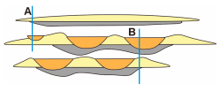 | |||||||||||||
| Lithofacies associations |  LA-1 | 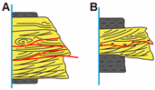 LA-2 |  LA-3, LA-4 |  LA-5, LA-6 | |||||||||||||
| Transport mechanism | Saltation dominated | Suspended-load dominated | Rolling dominated | ||||||||||||||
| Facies zone | River mouth to proximal delta front | Medial delta front | Distal delta front to slope break edge | ||||||||||||||
| Channel morphology and Paleotopographic |  | ||||||||||||||||
| Relative paleoslope | 0.73 | 0.97 | 0.85 | 0.09 | 0.13 | 0.07 | 0.08 | 0.05 | 0.09 | 0.15 | 0.75 | 0.64 | 0.50 | 0.47 | 0.44 | 0.60 | 0.56 |
| Paleoslope type | SS I | GS II | SS III | ||||||||||||||
| Topographic | I: Gentle to steep slopes | II: Steep to gentle slopes | III: Gentle to steep slopes | ||||||||||||||
Disclaimer/Publisher’s Note: The statements, opinions and data contained in all publications are solely those of the individual author(s) and contributor(s) and not of MDPI and/or the editor(s). MDPI and/or the editor(s) disclaim responsibility for any injury to people or property resulting from any ideas, methods, instructions or products referred to in the content. |
© 2025 by the authors. Licensee MDPI, Basel, Switzerland. This article is an open access article distributed under the terms and conditions of the Creative Commons Attribution (CC BY) license (https://creativecommons.org/licenses/by/4.0/).
Share and Cite
Huang, Y.; Yu, X.; Fu, C. Depositional Architecture of Aggrading Delta Front Distributary Channels and Corresponding Depositional Evolution Process in Ordos Basin: Implications for Deltaic Reservoir Prediction. Water 2025, 17, 528. https://doi.org/10.3390/w17040528
Huang Y, Yu X, Fu C. Depositional Architecture of Aggrading Delta Front Distributary Channels and Corresponding Depositional Evolution Process in Ordos Basin: Implications for Deltaic Reservoir Prediction. Water. 2025; 17(4):528. https://doi.org/10.3390/w17040528
Chicago/Turabian StyleHuang, Yuhang, Xinghe Yu, and Chao Fu. 2025. "Depositional Architecture of Aggrading Delta Front Distributary Channels and Corresponding Depositional Evolution Process in Ordos Basin: Implications for Deltaic Reservoir Prediction" Water 17, no. 4: 528. https://doi.org/10.3390/w17040528
APA StyleHuang, Y., Yu, X., & Fu, C. (2025). Depositional Architecture of Aggrading Delta Front Distributary Channels and Corresponding Depositional Evolution Process in Ordos Basin: Implications for Deltaic Reservoir Prediction. Water, 17(4), 528. https://doi.org/10.3390/w17040528