Abstract
Mapping the terrain and the Earth’s surface can be performed through non-contact methoYes, that is correct.ds such as laser scanning. This is one of the most dynamic and effective data collection methods. This case study aims to analyze the usability of spatial data from available sources and to choose the appropriate solutions and procedures for processing the point cloud of the area of interest obtained from available web applications. The processing of the point cloud obtained by airborne laser scanning results in digital terrain models created in selected software. The study also included modeling of different types of residential development, and the results were evaluated. Different data sources may have compatibility issues, which means that the position of the same object from different spatial data databases may not be identical. To address this, deviations of the corresponding points were determined from various data sources such as Real Estate Cadaster, ZBGIS Buildings, LiDAR point cloud, orthophoto mosaic, and geodetic measurements. These deviations were analyzed according to their size and orientation, with the average deviations ranging from 0.22 to 0.34 m and standard deviations from 0.11 to 0.20 m. The Real Estate Cadaster was used as the correct basis for comparison. The area of the building was also compared, with the slightest difference being present between the Real Estate Cadaster and geodetic measurement. The difference was zero after rounding the area to whole numbers. The maximum area difference was +5 m2 for ZBGIS Buildings.
1. Introduction
Spatial data compatibility is characterized based on the locations of the corresponding points from different sources or data providers. If we talk about the compatibility of geodetic points, we assume that the physical marks of points permanently stabilized on the Earth’s surface are identical to the data that define their location in the national reference coordinate system [1]. With the compatibility of spatial data from several sources, it is necessary to determine the positional deviations of the corresponding points of the fixed foundation of buildings in the selected coordinate system [2].
Mapping the landscape, terrain, and Earth’s surface has been among the most dynamic, efficient, and progressive branches of surveying in recent years, which thanks to the development of technology and software equipment and computer and geospatial technologies have made significant progress in the speed of spatial data collection.
Geospatial data collection methods can generally be divided according to the process and nature of the acquisition. Direct measuring methods are characterized by measuring or mapping directly in the field. Depending on whether the measurement is performed directly on the object or the ground, they are further divided into contact and non-contact methods. Geodetic measurements using a total station and Global Navigation Satellite System (GNSS) technology fall under contact data collection methods, while remote sensing, photogrammetry, laser scanning, and radar scanning are examples of non-contact data collection methods [3]. When data and models are used in a processed form (in the analog or digital format), these are indirect data collection methods. This involves digitization, vectorization, or scanning of photographic materials, aerial photographs, or analog maps [4,5].
Terrain and land surface mapping have made distinct and significant progress in providing geospatial data. Non-contact techniques are often used, providing a large amount of spatial data with high accuracy and density, capturing parts, elements, and components of the landscape or the Earth’s surface. Data obtained through non-contact techniques have become available in the digital form even for the standard user of geographic information systems (GISs). When choosing a non-contact data collection technique, we must consider the size of the mapped area, the required density of points, positional and height accuracy, the time required, and the price.
Laser scanning (LS) is an active method of RS of the Earth, which uses the reflection of electromagnetic radiation to capture the 3D geometry of objects, the surface, and the relief of the Earth’s landscape sphere [6]. It is also referred to as LiDAR (Light Detection and Ranging) and is currently the most effective and progressive method of collecting a large amount of 3D data (104–106 p/s) [7]. It has found use in various industries (geodesy, remote sensing (RS), archaeology, geology, transport, ecology, meteorology, forestry, and agriculture). The result is data in the form of a point cloud (with points in the range 106–108), from which digital terrain, relief, and height models are most often generated. Airborne LS, due to its highly economical and time-consuming nature, is directly intended for mapping the 3D geometry of the surface and objects of large areas, even in the case of hard-to-access locations from the surface [8]. ALS is one of the active methods of RS, with the help of which it is possible to obtain extensive data (up to 2 × 10⁵ p/s) for the creation of a digital relief model (DMR) of the country [7]. The advantage of this method is that it can capture the surface of the terrain even through vegetation, trees, or bushes, and it is widely used [9]. To determine the exact position of the observed object, it is necessary to thoroughly know the position and orientation of the scanner [10].
A combination of the GNSS receiver and the Inertial Measurement Unit (IMU) defines the scanner’s precise position, speed, pitch, and orientation. A GNSS reference station on Earth simultaneously monitors the LIDAR position [11]. These two devices enable data transformation into a static point cloud of the observed object with an absolute accuracy of 10–15 cm [8]. Terrestrial laser scanning (TLS) is more suitable for measuring objects or small landscape sections or supplementing ALS. TLS is based on obtaining a point cloud with a high density in a very short time. The color shade of the individual points is taken from the corresponding location of the corresponding photographic image created by the built-in camera in the scanner. Each point from the dataset contains coordinates X, Y, and Z, intensity I, and color shades R, G, and B [12,13]. Mobile laser scanning (MLS), placed on mobile platforms, such as a drone, car, boat, or backpack, is a current trend and consists of a scanner, an inertial system (gyroscopes and odometer), and two GNSS receivers [14]. A handheld scanner efficiently and quickly scans complex objects in 3D, enabling the creation of BIM (Building Information Model) of the existing buildings [15,16]. Combined with ALS, UAS Photogrammetry represents a powerful tool for detailed mapping [17].
Photogrammetry determines objects’ location, shape, and dimensions on the Earth’s surface by processing images from calibrated imaging cameras [18]. Increasing sensing device resolution and processing software performance enables capturing large objects and territories [19]. For processing, it is necessary to have the obtained images georeferenced based on ground control points or use GNSS data when creating the image [20]. The creation of a 3D model is based on optical scanning based on the similarity of images, which results in a point cloud. The condition comprises an uneven surface texture and not too much deep fragmentation [21]. Aerial photogrammetry is usually carried out during the topographical mapping of large areas using an aircraft with a special photogrammetric (multispectral) camera. The processed output can be a digital orthophoto mosaic or orthophoto maps in the chosen coordinate system [22]. The accuracy of the digital orthophoto map is characterized by the mean positional error (root mean square error—RMSE) with the calculated circular error (circle error—CE) at the selected level of significance [23]. UAS imaging has a relatively low cost, higher resolution, greater load that negatively affects flight length, and increased sensitivity to meteorological conditions [3]. Close-range photogrammetry takes pictures with a measuring camera from a fixed position on the Earth’s surface at object distances of approximately 0.1–350 m. Close-range photogrammetry in measuring and creating 3D models of buildings, e.g., of cultural heritage, uses photographs of objects taken from the perspective sides [24,25]. Subsequent processing provides more detailed modeling of facades compared to their sloping roofs, which are not scanned from a vertical view [26]. The more detailed modeling of the entire building, including the roof, allows supplementing aerial images from a drone [27] with GNSS PPK (Postprocessing Kinematic) technology, which ensures georeferencing of images without the use of ground control points [28]. Like MLS on a car, tricycle, or backpack, photogrammetric cameras allow the recording of georeferenced panoramic images of cities, castles, or national parks [29,30].
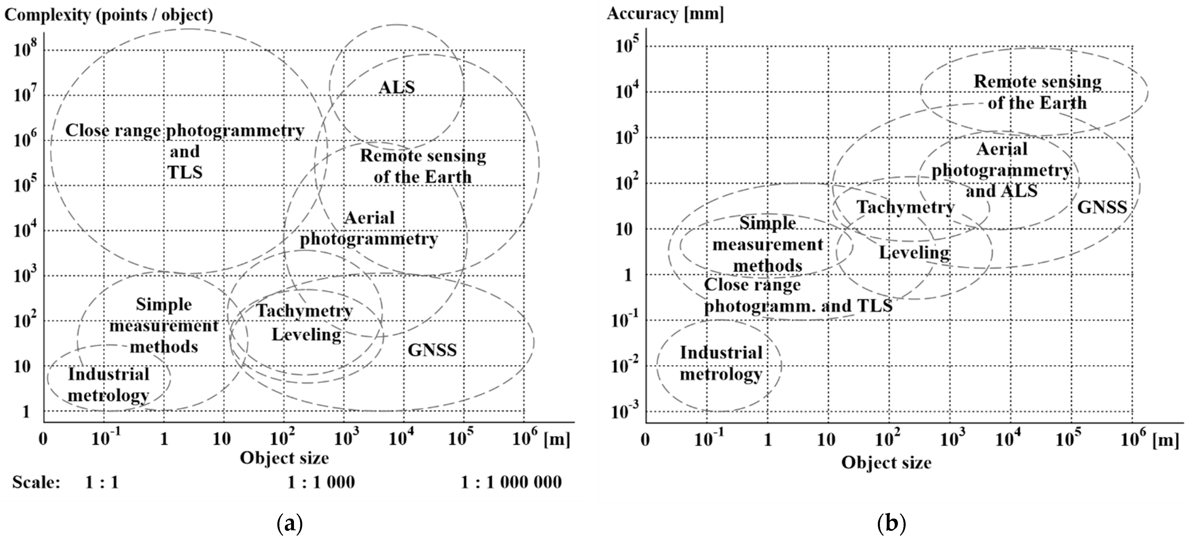
The overall evaluation of spatial data collection methods can be expressed from the relationship of the object (territory) size to the assumed number of determined spatial data in the graphical visualization shown in Figure 1a and from the relationship of the object (territory) size to the assumed achieved accuracy in the graphical visualization shown in Figure 1b. Combining data collection methods in terms of their strengths or weaknesses is appropriate.
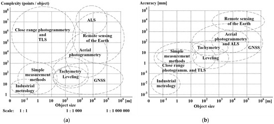
Figure 1.
Graphical visualization of different measurement methods in the relationship between (a) object size and number of points on object and (b) object size and measurement accuracy.
2. Materials and Methods
This study aims to examine the compatibility of spatial data obtained from a specific location in the village of Horné Srnie. The study started by analyzing spatial data from various sources in the Bentley CAD environment. Next, DTM and 3D building models were created. This study analyzed the compatibility of the corresponding points from the available spatial data sources of the given location. The positional deviations of the selected object between different spatial data sources were determined.
2.1. Study Area
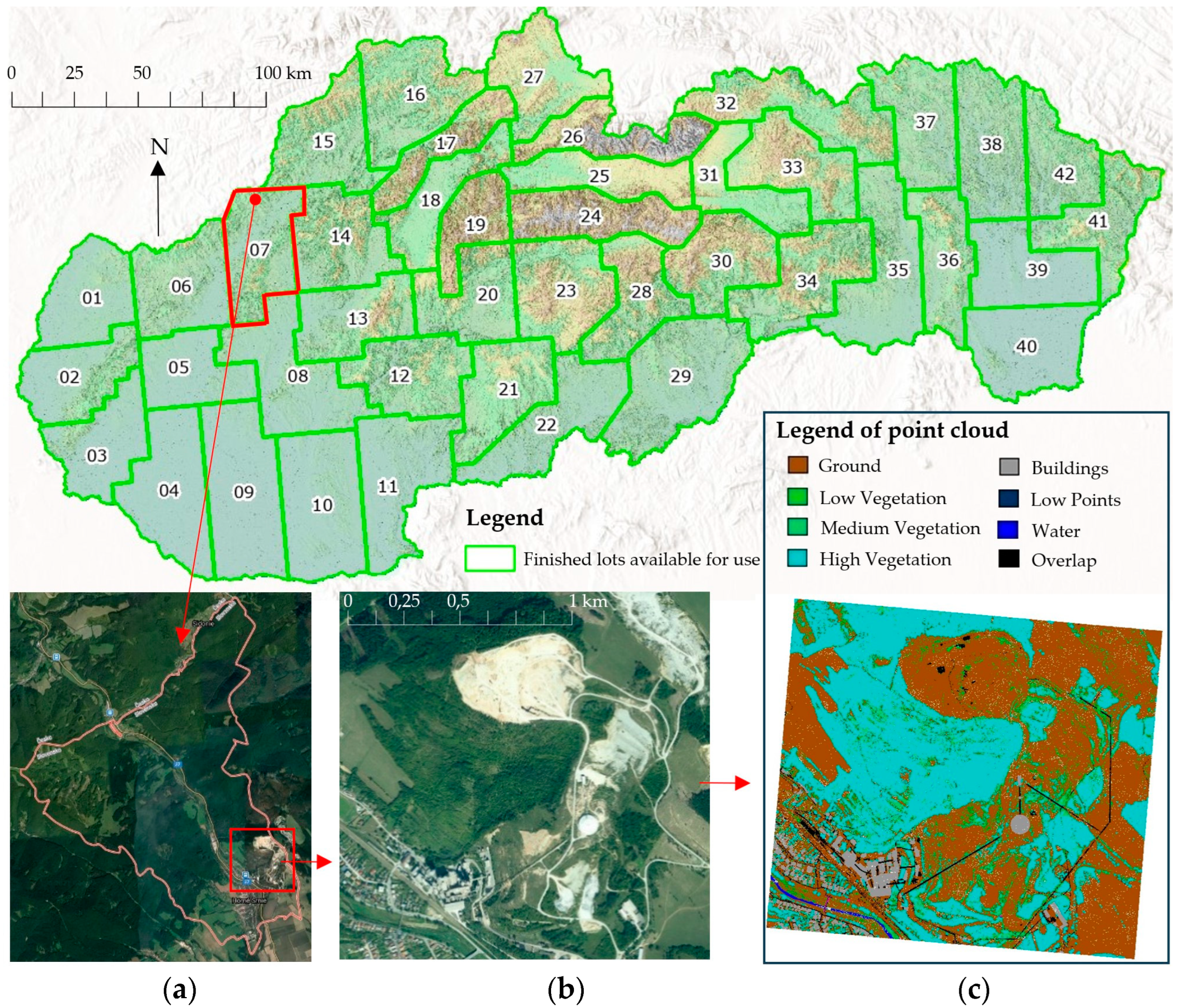
The selection of the study area was preceded by considering several criteria (coverage of the region with ALS data, availability of other spatial data, the degree of representation of residential development in the built-up area, and the anthropogenic areas outside the built-up area of the village). This study has selected an area of interest in the cadastral unit of Horné Srnie. Horné Srnie (Figure 2, Table 1) is the northernmost village in the Trenčín district. It lies on both banks of the Vlára River, almost 17 km from the regional town of Trenčín. Near the village is an open pit mine on the Ostrá Hora hill, where marly limestone and marl are mined for the nearby cement plant. The selected area for this study (49°00′02″ N, 18°07′20″ E) with dimensions of 1.4 × 1.4 km represents a part of the built-up area of the village, the cement plant, and the open pit mine.
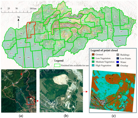
Figure 2.
Localization of the selected area of study from Slovakia based on the regions from which data are provided from the ALS: (a) cadastral unit of Horné Srnie village; (b) orthophoto mosaic of the study area; and (c) classified point cloud of the study area.

Table 1.
Study area.
2.2. Data Collection
Spatial data are ubiquitous today, and work with it is provided by various state authorities, ministries, and private companies on their websites. The best-known private companies for providing spatial data in Slovakia are Geodis, Geodeticca, Photomap, etc., which commercially provide spatial data, orthophoto maps, or digital terrain models. Of the state institutions that provide geospatial data, it is possible to name, in particular, the Geodesy, Cartography and Cadaster Authority of the Slovak Republic (GCCA SR) and then narrowly specialized data provided by the Ministry of Agriculture and Rural Development of the Slovak Republic, Railways of the Slovak Republic, various geological and water management institutes, etc.
In this study, the input spatial data were provided by GCCA SR (Table 2), either downloaded via the ZBGIS Map Client (LiDAR point cloud) or connected via web map services (WMSs). GCCA SR is coordinating the completion of the collection of spatial data by airborne laser scanning (ALS) or the next cycle of data collection from aerial photogrammetry (AFg) on the territory of Slovakia. ALS in Slovakia is taking place gradually at 42 locations from west to east, and currently (May 2024), a point cloud is available from all 42 localities [31]. The last four localities do not provide a classified point cloud. AFg, under the coordination of GCCA SR, is already in the phase of completing the creation of the second cycle of orthophoto mosaics in Slovakia since 2020 [32]. In the Slovak Republic, the two-dimensional projected coordinate system is the “Datum of Uniform Trigonometric Cadastral Network” (D–UTCN) that is Krovak’s projection with x southing and y westing values and with the implementation UTCN/UTCN03, and the vertical system is “Baltic Vertical Datum–After Adjustment” (BVD–AA) [33,34].

Table 2.
Input data from Geodesy, Cartography, and Cadaster Authority of the Slovak Republic.
Eleven LAS format files were obtained from the selected location, representing point clouds from different flight lanes. Data were used in available open-source (CloudComapre) and commercial (Bentley) software environments. However, unifying the coordinate system of all spatial data in the software is necessary to correct point cloud processing. The software CloudCompare 2.12 (open source) made it possible to work with the point cloud: to segment the data, distinguish colors, and sample, register and provide a high-quality display of the data [35]. Our input data were further processed in the software environment Bentley OpenRail Designer Connect Edition 10.12.02.04 [36]. A Scalable Terrain Model (STM) was created in Bentley Descartes Connect Edition 10.17.02.14.
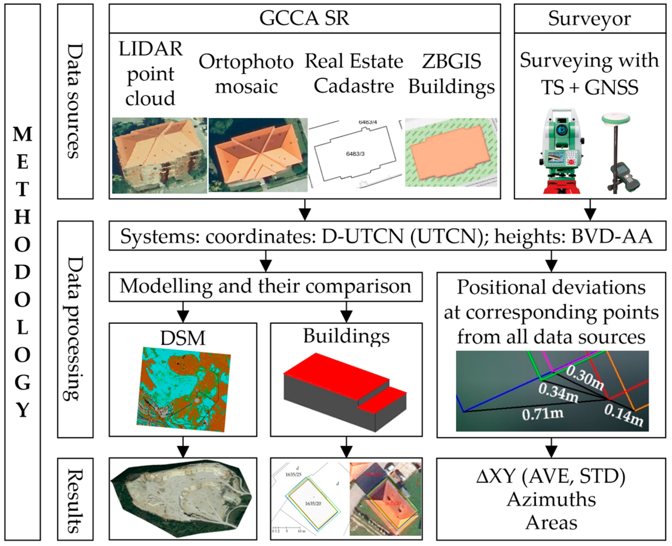
When using spatial data from different sources, the level of their mutual agreement is unclear. The accuracies of the spatial data from the provided sources are listed, but they sometimes do not correspond to the facts. The main goal and, at the same time, the novelty of this scientific study are the analysis of the compatibility of freely available spatial data based on positional data in terms of accuracy of deviations of corresponding points of the fixed foundation of the selected building and their applicability for further use in the CAD environment (Figure 3). A part of the solution also focuses on errors that may occur in the input data and their processing. LiDAR point cloud, orthophoto mosaic, and vector data from information systems in Slovakia (Real Estate Cadaster, ZBGIS Buildings–basic database for the geographic information system) were chosen as input data. The same coordinate system was used for all spatial data, including its implementation. It is important that, before importing data or connecting layers, the desired implementation of the coordinate system of the data or layer is selected, and then, the distances between the two corresponding points in the two layers is measured when viewed from above. Subsequently, the positional deviations of the corresponding points were determined and analyzed according to size and orientation. If the values of the deviations of the corresponding points are small, it can be concluded that they are compatible data sources. If they are large, they are incompatible and unsuitable for further joint processing. A systematic research approach cannot be easily applied to a larger number of buildings. When determining the corresponding points forming the fixed foundation of the building, the problem arises that many buildings have roof edges wider than the fixed foundation of the building. It is problematic when using buildings with a projecting roof (they are the predominant majority) because the corresponding roof in the orthophoto covers their solid foundation. It would only be estimates of the solid foundation of the orthophoto. Thus, the comprehensive approach is not fulfilled.
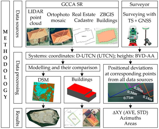
Figure 3.
Methodology of the case study of the positional deviations of the corresponding points.
The analysis was also carried out based on terrain and building modeling. The class Ground from ALS point cloud and orthophoto mosaic data was used for modeling the study area. DTMs were created to explore the mining process and monitor the impact on the site’s natural environment. For various studies, the simple 3D modeling of buildings has shown its advantages and disadvantages in modeling and composition of the building object. LiDAR ALS—airborne laser scanning [37]—is most suitable for modeling buildings and the shape of their roof surfaces. Aerial photogrammetry with output in the format of aerial images [38], high-resolution satellite images [39], and InSAR [40] can be used as additional data sources. Methods for creating a 3D model of building objects were based on LiDAR ALS [41], with the support of close-range or aerial photogrammetry with high resolution [42].
2.3. Level of Detail for Building Modeling, a Transformation of Implementation Coordinate Systems, and Digital Elevation Models
The methodology of 3D modeling of buildings from a point cloud of LiDAR data are presented in studies [43,44,45]. From the point of view of the complex processing of the 3D building model, it is necessary to consider up to five levels of detail (LOD), i.e., LOD0, LOD1, LOD2, LOD3, and LOD4 [46]. The height of the modeled building can be chosen in different height levels of building H0-H6 [47] (Figure 4).

Figure 4.
Levels of detail (LOD) in modeling 3D objects.
The floor plan of the building or the edge of the roof forms LOD0. LOD1 is a simple block model (LOD0 + building height). LOD2 is a model with a simplified shape of the roof and walls of the building. LOD3 represents a building model with exterior details of the facade and roof (windows, doors, roof windows, chimneys, etc.) [48]. The 3D model at the LOD4 level also has an interior structure that can be obtained from additional TLS or MLS of the interior.
Due to the modeling of 3D buildings and their comparison with the ZBGIS and Real Estate Cadaster layers, it is necessary to apply the Shift Grid Model for the point cloud, which serves to transform the implementation of UTCN03 into the implementation of UTCN at the level of the Bessel ellipsoid. On the website, in the report of the GCCA SR [31], it is stated that the transformation shift model includes vectors of coordinate differences defined in the implementation of UTCN03 at 684 corresponding points. The set of corresponding points is the same as when calculating the seven Helmert transform parameters of the global transform key for Slovak Republic. The calculated coordinate differences characterize the systematic inhomogeneity of the UTCN frame but do not adequately describe the detailed inhomogeneity of smaller locations at the cm level. Based on this transformation, the point cloud can be transformed into the D-UTCN coordinate system (UTCN), EPSG code: 5514.
3. Results
LiDAR data represent a suitable data source, but we cannot say that it is an ideal data source, primarily due to the limitation of insufficient capture of building facades or roofed areas (bus platforms, gas stations, etc.) [43]. A lot of data obtained through laser scanning must be prepared and processed. The result of laser scanning processing is a classified cloud of points, in which each point is assigned the measurement number, spatial coordinates determining its position on the Earth’s surface, the intensity of reflection, classification, and other additional information such as the angle of incidence during scanning, the number of returns, return number, scan direction, or GPS time. The point cloud can be displayed using these parameters for the possible data selection. Before working with the point cloud in Bentley, applying the “Shift Grid Model” [31] is necessary to transform the spatial data in D-UTCN from the implementation of UTCN03 to UTCN. National transformations defined by EPSG codes incorporated directly into the Bentley software under the coordinate systems tool were used to transfer to a uniform implementation of the coordinate system. For the better manipulation of the point cloud, merging *.las files from different flight strips into one file using the merge multiple cloud function is necessary. The classification of the point cloud into classes from the selected area (Table 3) was performed by an external supplier of ALS results for GCCA SR.

Table 3.
Classification of point clouds in *.LAS format.
The classification shows that 53% of the data consists of vegetation, 44% of the Earth’s surface, less than 2% of buildings, and other classes represent 1% of the data. Interestingly, the high noise class comprised conveyors in an open pit mine and a mining enterprise.
3.1. Modeling of the Area of Interest
A DTM is created by filtering out all classified point classes except those containing the Earth’s surface points. The display of point cloud is according to classification attributes (Figure 5a) and reflection intensity (Figure 5b). DTM is modeled from the Ground layer using the Terrain function, where the best visualization is represented by the Smooth Modeling style (Figure 5c).

Figure 5.
Point cloud visualization of the study area: (a) display of colored point cloud according to classification in Table 3; (b) display of point cloud according to reflection intensity; and (c) DTM displayed with Smooth Modeling visualization style.
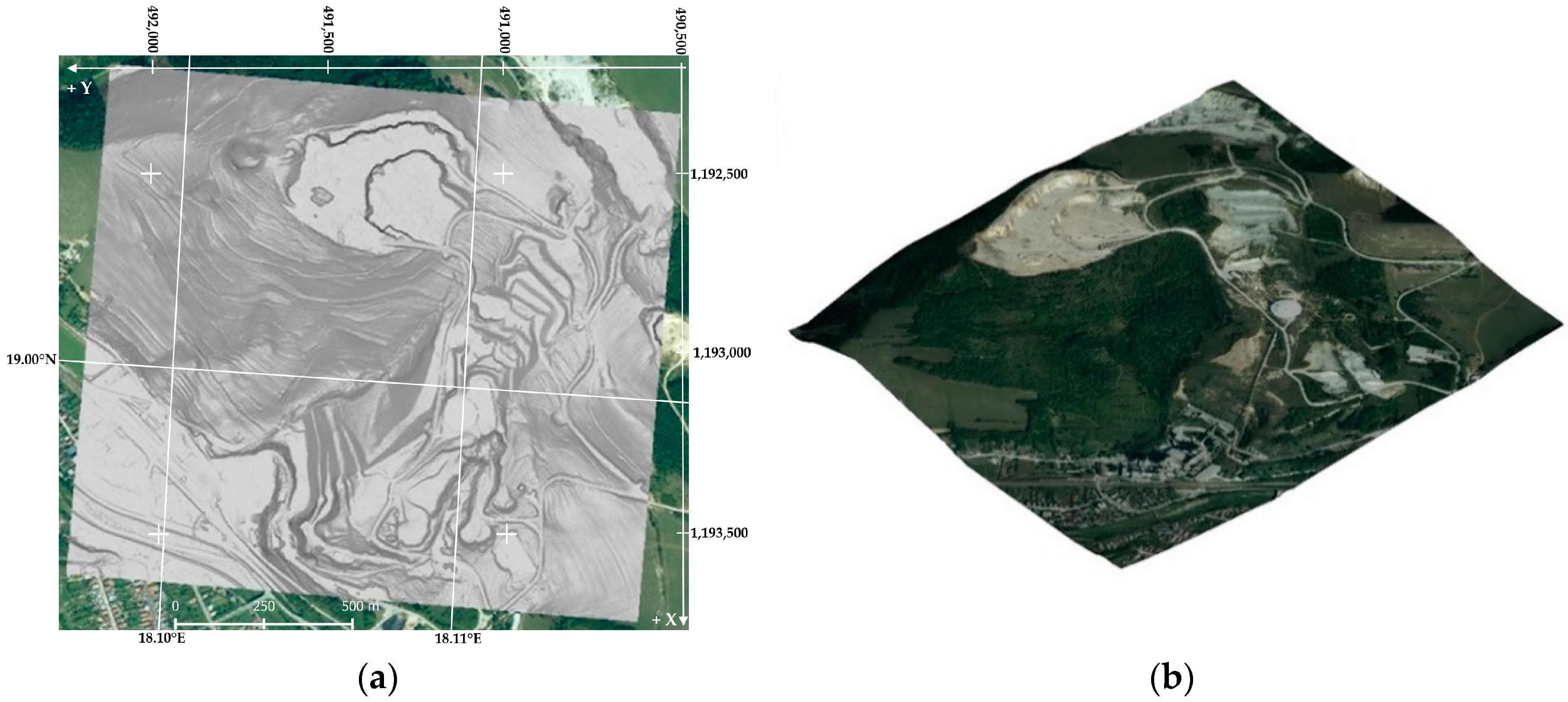
For better presentation, orientation, and up-to-dateness, but also to check the correctness of the modeling and the position of the DTM, the orthophoto mosaic (*.wms) is attached (Figure 6a). The DTM ideally feeds and adheres to the orthophoto mosaic. The literature [49] defines the Scalable Terrain Model (STM) as an improved type of function with the possibility to create and display extensive digital terrain models with a classic orthophoto mosaic overlay (Figure 6b). Then, an actual DTM of the study area is obtained. Based on previous comparisons, it can be concluded that the data are equivalent at the given display scale and the available resolution of the image backgrounds.
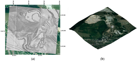
Figure 6.
Visualization of the subject area: (a) DTM display with orthophoto mosaic connection and (b) view of DTM with orthophoto mosaic overlay.
3.2. Open Pit Mine Modeling and Data Analysis
In the point cloud from the open pit mine area in the village of Horné Srnie, the active layers, Ground (the Earth’s surface) and Unassigned (marked in white), were left. The Unassigned layer contains the points of accumulated material that must be included in the DTM. Various machines used to extract and transport material that does not belong to the DTM are in the high noise layer (marked in black) (Figure 7a). It is necessary to apply these approaches, and the result of merging suitable points from Unassigned to Ground is shown in Figure 7b. TLS solves this problem with a double scan of the area, where moving objects are excluded from processing, and only duplicate objects and terrain are left. This principle is also applied in ALS when performing scanning from different flight lanes at the expense of reducing the density of point cloud, e.g., people on the street. The merged point cloud was created, e.g., the contour model, or DTM, and after overlaying with orthophoto mosaic, it represents a realistic 3D model (Figure 7c).

Figure 7.
Display of cropped point cloud of the open pit mine surface: (a) display of point cloud Ground (open pit mine surface—brown color), Unassigned (embankments—white color), and hight noise (loaders—black color); (b) view of the merged point cloud (Ground and Unassigned); and (c) DTM overlaid with orthophoto mosaic in 3D iso view.
These DTMs can be used for modeling geological and geomorphological processes or analysis of geomorphological structures. Among the technical disciplines, DTM is particularly suitable for the needs of management and strategic planning for making a mining map of the open pit mine. The detailed analyses of the open pit mine can be a suitable basis for the continuation, expansion, or completion of the mining process in the following years or for monitoring the environmental impact with the subsequent reclamation of the mining area after the end of the mining process.
3.3. Simple Non-Automated 3D Modeling of Buildings for Various Studies
Methods for creating a 3D model of buildings are based on aerial laser scanning data. The 3D model of individual buildings is compiled from LIDAR data, which represents the actual locations, dimensions, and structures of the buildings. Two buildings were chosen from the selected area—the first is a warehouse building with a flat roof. The second is an apartment building with a sloping roof. There were no windows and doors on the 3D building models at the LOD2 level. The 3D building models are modeled using the perpendicular section and DSM.
3.3.1. Warehouse Building with a Flat Roof and No Edges
Only Ground and Building classes are used for further modeling processing using point cloud classification. Horizontal and vertical sections of the building are made in the Bentley OpenRail Designer program, from which a wire model of the building (Figure 8a) with dimensions of 13.9 × 6.2 × 3.9 m is created. The wireframe 3D model of the walls and roof in two height levels were filled with gray and red colors (Figure 8b). A simple model of the building at the LOD2 level without windows and doors will be created, which can be made if we do not have geodetic technology available. A higher level of LOD3 of a building can be obtained by scanning its facade and expanding the wireframe model by creating windows and doors.

Figure 8.
Comparison of models of the warehouse building with a flat roof: (a) view of the classified point cloud around the building and the wireframe; (b) filling the wireframe without the point cloud; (c) generated building model from the point cloud as DSM; and (d) 3D building model visualized in ZBGIS.
The second procedure for creating a 3D model of a building is to generate a DSM from a classified cloud of points (Ground and Buildings). Automatic DSM generation is used, and a 3D building model is generated in the Smooth Modeling visualization style (Figure 8c). The edges of the building are problematic, where points with different altitudes and approximately the same coordinates create narrow and tall needles. And for this reason, the whole building, including the roof, is unrealistic. The warehouse building from the ZBGIS Buildings data source has a simple 3D visualization at the LOD1 level (Figure 8d).
3.3.2. Apartment Building with a Hipped Roof
An apartment building with a hipped roof in the village of Horné Srnie is also modeled from the point cloud using both methods (Figure 9a). The apartment building will be modeled using horizontal and vertical sections into a wire model with dimensions of 16.5 × 9.7 × 11.5 m with a hipped roof at the LOD2 level (Figure 9b). DSM modeling was used from the point cloud where the hipped roof type is visible in the Smooth Modeling visualization style (Figure 9c). In the case of a wide edge of the roof, the same problem is of a larger scale than in the previous case. But the face of the roof, compared to the previous model, is more realistic. The resulting 3D model of the apartment building is also influenced by the point cloud of chimneys and antennas on its roof. This apartment building displayed from the ZBGIS Buildings data source is at the LOD1 level, which has a simple 3D visualization and does not have information about the type of roof, namely, the hipped roof (Figure 9d).

Figure 9.
Comparison of models of the hipped-roof apartment building: (a) view of the classified point cloud around the building; (b) filling the wireframe without the point cloud; (c) generated building model from the point cloud; and (d) 3D building model visualized in ZBGIS.
3.3.3. Analysis of the Location of the Modeled Buildings
All available spatial data (Table 2) must be added or connected to the software environment Bentley OpenRail Designer and Descartes. The positional representations of two modeled buildings from the classified point cloud from ALS based on orthophoto mosaic, ZBGIS Buildings, and the Real Estate Cadaster were compared (Figure 10a,b—orientation of map situations is to the north). The warehouse building, defined in the cadaster as a built-up area and courtyards, has a rather significant discrepancy from different databases during the border (Figure 10a). Apartment buildings with roof edges are better off as the boundary mismatch is smaller and will be hidden under the roof edges. For example, the ZBGIS Buildings source (blue line) has a minimum positional deviation of 0.14 m in the eastern corner of the apartment buildings with the boundary of the built-up area (solid green line) (Figure 10b). In the western corner of the subject building (blue line), there is a minimum difference with the edge of the roof (dashed green line) with a value of 0.22 m, and with the boundary of the built-up area, there is a positional difference of 1.33 m. According to the data provider, ZBGIS Buildings was created based on aerial photogrammetry since 2008, confirmed by this analysis. Most of the buildings on the orthophoto mosaic have one corner of the building visible, and the opposite corner of the same buildings represents the edge of the roofs of regular buildings. In this case, study, 3D models of two buildings were created, which we can classify into LOD2 and LOD3 levels of detail.

Figure 10.
Positional comparison of buildings on orthophoto mosaic and Real Estate Cadaster: (a) warehouse building with a flat roof and two height levels and (b) apartment building with a hipped roof.
3.4. Detailed Determination of Positional Deviations on Corresponding Points
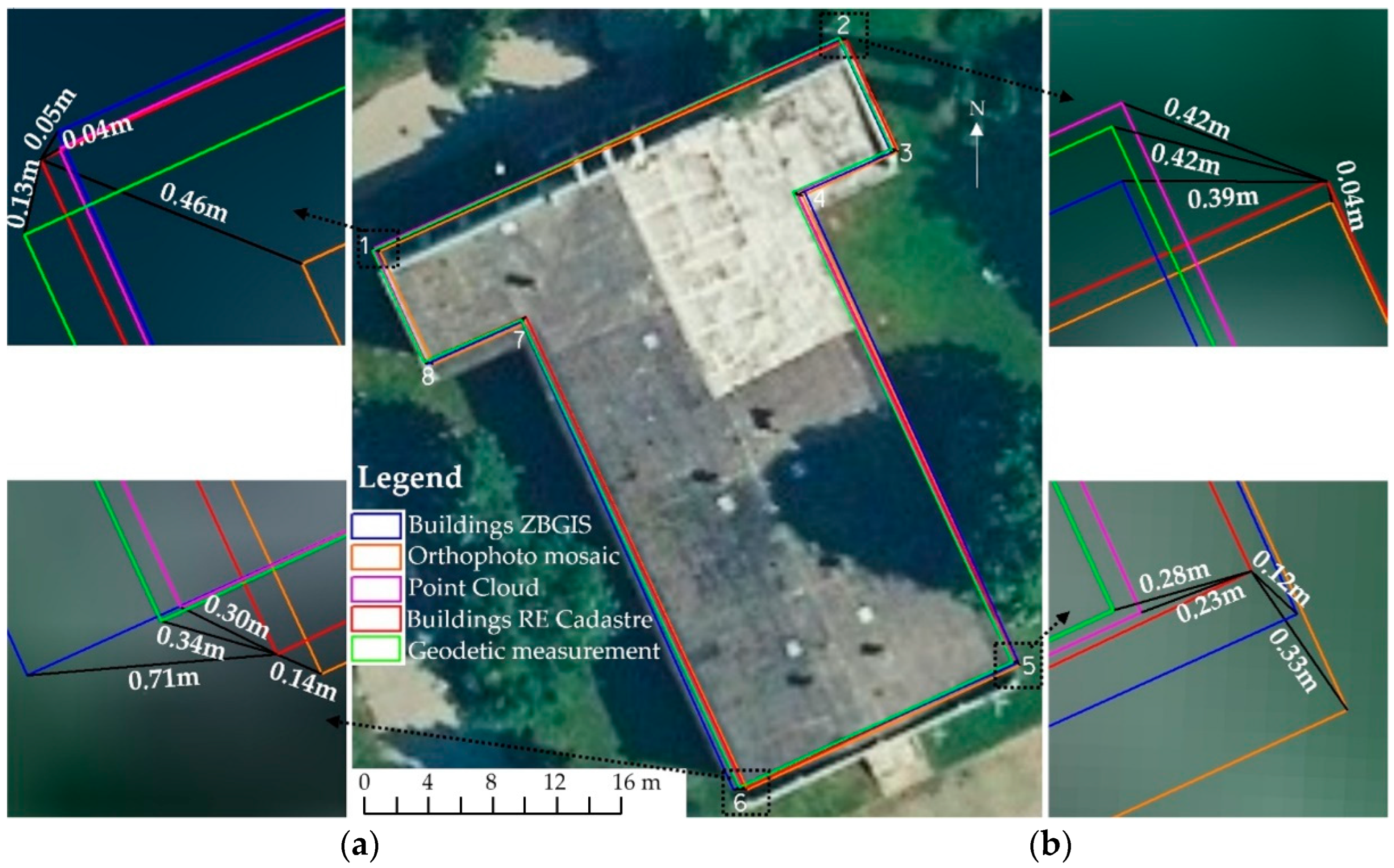
To determine compatibility, comparing the accuracy of matching spatial data from individual sources is necessary. Spatial data must be stored in individual layers below each other for comparison. When importing them into separate layers, it is also necessary to unify the implementations of coordinate systems of compared spatial data sources. Subsequently, the sizes of the positional deviations at selected corresponding points are determined. One simple spatial object (a building without roof edges) was selected, and the compatibility of data from different sources was compared (Figure 11). The most work for comparison was with the point cloud of LiDAR because it is the most complex non-selective spatial data.
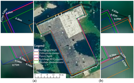
Figure 11.
Compatibility of corresponding points—corners of the selected building together with a detailed display of their positional deviations: (a) left—points 1 and 6 and (b) right—points 2 and 5.
The class Building was used from the LiDAR point cloud to determine the positional deviations of the corresponding points. The corners of the building mentioned above were chosen as the corresponding points. The compatibility of these corner points was measured between all selected spatial data sources: LiDAR (cloud point), ZBGIS (Buildings), Real Estate Cadaster, and an orthophoto mosaic. Compared to the previous analysis of building locations, another source of data was added—geodetic measurement. A horizontal section of the building was selected from the point cloud (LiDAR) and then translated by line segments. A floor plan of the building was created, which was compared with the other mentioned spatial data. All data are implemented into UTCN. The positional deviations are shown between the corresponding points in Figure 11a,b, and their sizes and azimuths are presented in Table 4. Graphical data from the Real Estate Cadaster were chosen as the basis for the comparison, which were compared at all corresponding points with other data sources.

Table 4.
Comparison of the compatibility of all corresponding points of the building by displaying their size, the orientation of the analyzed positional deviations, and the size of the building area too.
3.5. Determination of Positional Deviations of Buildings
To determine compatibility, comparing the accuracy of matching spatial data from individual sources is necessary. Based on the methodology from Section 3.3 and Section 3.4, the positional deviations of the corresponding points on the selected 35 construction objects connected to the ground with a solid foundation were determined in the study location. Deviations were determined based on the Real Estate Cadaster to spatial data from LiDAR point cloud, ZBGIS Buildings, orthophoto mosaic, and geodetic measurements. Table 5 was created from the processed positional deviations, where the values of positional deviations are displayed, namely, the minimum value (MIN), the maximum value (MAX), the arithmetic mean of the positional deviation = average positional deviation (AVG), and the variance of the positional deviation = standard deviation (STD).

Table 5.
Comparison of the positional deviations of all corresponding points of the selected buildings by displaying their size.
4. Discussion
Between the Real Estate Cadaster and ZBGIS Buildings data, a maximal deviation of up to 0.71 m and an average position deviation of 0.34 m was detected on one “T”-shaped building. The most significant positional deviation when comparing the graphic background data of the Real Estate Cadaster and the point cloud obtained by ALS reaches a value of 0.42 m with an average deviation of 0.22 m. When comparing the graphic background data of the Real Estate Cadaster and orthophoto mosaic, the positional deviation reaches a maximum positional deviation of 0.52 m and an average deviation of 0.29 m. The analysis was extended to include the geodetic measurement of the given building to confirm the results achieved. The geodetic measurement of the building was carried out using a combination of a Leica GNNS receiver and a Leica total station, where all breaking points of the building’s solid foundation were determined. If we compare the geodetic measurements with the graphic background data of the Real Estate Cadaster, the maximum positional deviation reaches 0.42 m and with an average deviation of 0.28 m. The displacement of individual layers from the underlying data of the buildings of the Real Estate Cadaster was also examined from the point of view of the direction of rotation, which was determined based on the size of the azimuth. Azimuth is the angle subtended between the plane containing the given target point and the plane of the given meridian and is measured from north to east. The shift of the ZBGIS Building layer, the point cloud layer obtained by ALS, and the geodetic measurement compared to the underlying data of the Real Estate Cadaster buildings does not agree. The shift in comparing the graphic background data of the Real Estate Cadaster and orthophoto mosaic is towards the southeast of different sizes. The AVG ranged from 0.22 to 0.34 m, where the Real Estate Cadaster was used as the basis for comparison. If we take individual data sources together, the minor average positional deviation of the corresponding points was 0.07 m between the LiDAR point cloud and geodetic measurement. We also determined the STD of positional deviations, where the smallest value of 0.11 m was between Building Real Estate Cadaster and Geodetic measurement, and the largest value of 0.20 m was for ZBGIS Building.
When comparing the area of the building in question, there is zero difference between Real Estate Cadaster and geodetic measurement after rounding the area to whole numbers (zero decimal places) (Table 4 marked with *). The maximum area difference is +5 m2 for ZBGIS Buildings. For LiDAR point cloud and orthophoto mosaic, the difference in building areas was about 3 m2.
By processing the positional deviations of the corresponding points of 35 buildings from various sources of spatial data, the data presented in Table 5 were obtained. In these data, the LiDAR point cloud has the smallest positional deviations to the Real Estate Cadaster, which has a maximum value of 0.44 m with an average positional deviation of 0.17 m and standard deviation in position 0.12 m. Subsequently, according to the size, the positional deviations from the geodetic measurement were with a maximum value of 0.52 m and an average deviation of 0.26 m. The average deviation from the orthophoto mosaic was 0.32 m with a maximum value of 0.78 m. The worst accuracy or the largest deviations were achieved by the corresponding points of buildings from the source of ZBGIS Buildings, where the average deviation was 0.63 m and with a maximum value of 2.25 m.
If we compare the positional deviations presented from one “T”-shaped building with the deviations obtained from a group of 35 buildings, the values of the ZBGIS Buildings source have changed the most, where the average positional deviation has almost doubled. Other data did not show such significant changes from Table 4 and Table 5.
When choosing buildings, it was also considered that they had to be registered in all sources of spatial data. Buildings that were removed in the field, but were recorded in some sources, were not included in the study. Furthermore, the study did not include buildings that were created after aerial laser scanning (LiDAR point cloud) or aerial photogrammetry (orthophoto mosaic) but were already registered in the Real Estate Cadaster. The presented positional deviations could also be caused by the reconstruction of the building or roof, where spatial changes are recorded only in some sources. An increase in quality would certainly benefit if all data sources were created on the same date. The time difference in the creation of spatial data reduces the accuracy or increases positional deviations. For example, data recorded in the Real Estate Cadaster from a historical (temporal) point of view are determined over time with increasingly higher accuracy thanks to the development of GNSS technologies before its use in the Real Estate Cadaster. Compared to the LiDAR point cloud, which records all data for a few flights in a short time interval, the data of the Real Estate Cadaster was created by gradually updating the data from geodetic measurements based on the registration of ownership rights to real estate. ZBGIS Buildings are the worst because they are not updated so often and in detail.
The consequence of the differences is the technology (device) used to determine the location of the survey points registered in the Real Estate Cadaster and the technology for obtaining and processing the documents used to determine positional deviations at the corresponding points. Based on the sizes of positional deviations, their STD, and the size of the area in question, the expert reader can decide which source of spatial data to use when solving the order. It would be ideal if data from TLS, MLS, or UAV photogrammetry were also available in addition to geodetic measurements. But that will be the subject of further research.
From the point of view of accuracy, it is possible to conclude that, for GIS applications, these results are more than sufficient, where the accuracy of the results may not be as high and reliable (it is in the order of decimeters). From the geodetic point of view of accuracy, higher accuracy is required (ordered in centimeters), especially for legal purposes for determining ownership rights to problematic property or land boundaries. Classic (non-automated) procedures for creating 3D object models are suitable primarily for individual separate objects or tiny territories, as they require much time. Modeling based on rules has excellent potential from that point of view, as it is based on a programming language and defines individual objects with it, significantly saving time depending on the size of the territory and the number of buildings on it [50,51]. This method of modeling and creating 3D models of cities is significant, mainly for urban planning [52].
5. Conclusions
The study area was selected for this study, including the open pit mine, the conveyors, the mining enterprise itself, and residential development. A partial goal was to summarize spatial data from available sources from different providers. Another goal of the work was the creation of different types of DTM, building models in selected software environments from a classified point cloud in the LAS format.
When modeling the study area from ALS data, the Ground and Unassigned classes were used, and STM was overlaid with an orthophoto mosaic to create a realistic terrain surface. During the detailed modeling of the surface open pit mine, it was also necessary to consider the points of the Unassigned class, which represented terrain points standing out from the surrounding terrain (heaps and isolated stones), but not the high noise class, which was represented by construction or mining machines located in the open pit mine. Digital terrain models made in Horné Srnie can be used for modeling geological and geomorphological processes or analysis of geomorphological structures. Among the technical disciplines, DTM is particularly suitable for management, strategic planning, and creating a mining map of the mining area in the Horné Srnie municipality. The detailed analyses of the open pit mine can be a suitable basis for the continuation and completion of the mining process in the following years and for monitoring the impact on the natural environment, including reclamation after mining.
For various studies, the simple non-automated 3D modeling of buildings has shown its advantages and disadvantages in modeling and composition of the building object. Building modeling based on horizontal and vertical sections from the point cloud is plausible but requires more time. In this case study, two types of 3D models were created that we can classify into LOD2. A big problem in automated modeling is the edges of roofs, which have larger dimensions than the solid foundation of the building and significantly distort the resulting model. Based on the comparison of the location of the buildings, this aspect is satisfactory for the needs of GIS use. Still, it is insufficient for geodetic needs because the solid foundation of the building does not correspond to the edge of the roofs.
The deviations of the corresponding points were determined from various data databases (Real Estate Cadaster, ZBGIS Buildings, LiDAR point cloud, orthophoto mosaic) and geodetic measurements, subsequently analyzed according to their size and orientation. The average deviations ranged from 0.18 to 0.63 m, where the Real Estate Cadaster was used as the primary data source for comparison. When comparing the area of the building in question, the smallest difference is between Real Estate Cadaster and geodetic measurement, which is a zero difference after rounding up the area to whole numbers. The maximum area difference is +5 m2 for ZBGIS Buildings. The values of the positional deviations, their AVG and STD, or the size of the area in question will help the readers decide when solving the task and choosing suitable spatial data sources. Not a single source of spatial data is suitable for geodetic mapping work. All documents are suitable for GIS use. In future research, to further monitor the compatibility of spatial data using the corresponding points, data from TLS, MLS, or UAV photogrammetry could be supplemented.
Author Contributions
Conceptualization, S.L. and P.P.; methodology, S.L.; software, S.L. and P.P.; validation, S.L., P.P., P.S. and L.L.; formal analysis, S.L., P.P., P.S. and L.L.; investigation, S.L.; resources, S.L.; data curation, S.L. and P.P.; writing—original draft preparation, S.L. and P.P.; writing—review and editing, S.L. and P.P.; visualization, S.L. and P.P.; supervision, S.L, P.S. and L.L. All authors have read and agreed to the published version of the manuscript.
Funding
This research was supported by the Slovak Research and Development Agency under contract KEGA grant no. 003TUKE-4/2023, 011TUKE-4/2024.
Data Availability Statement
Data are contained within the article.
Acknowledgments
The authors also thank the Geodesy, Cartography, and Cadaster Authority of the Slovak Republic for providing the ALS data.
Conflicts of Interest
The authors declare no conflicts of interest.
References
- Weiss, G.; Weiss, E.; Weiss, R.; Labant, S.; Bartoš, K. Survey Control Points: Compatibility and Verification, 1st ed.; Springer International Publishing: Cham, Switzerland, 2016; 118p. [Google Scholar] [CrossRef]
- Weiss, G.; Gašinec, J. The compatibility investigation of 2D geodetic points by using the GPS technology. Acta Montan. Slovaca 2005, 10, 2. Available online: https://actamont.tuke.sk/pdf/2005/n2/28weiss.pdf (accessed on 3 August 2023).
- Colomina, I.; Molina, P. Unmanned Aerial Systems for Photogrammetry and Remote Sensing: A Review. ISPRS J. Photogramm. Remote Sens. 2014, 92, 79–97. [Google Scholar] [CrossRef]
- Pacina, J.; Brejcha, M. Digital Terrain Models, 1st ed.; Univerzita J. E. Purkyně v Ústí nad Labem: Ústí nad Labem, Czech Republic, 2014; 73p. [Google Scholar]
- Data Collection for GIS. Available online: http://www.pce.sk/clanky/body_zbor98_2.htm (accessed on 5 May 2022).
- Bruggisser, M.; Hollaus, M.; Wang, D.; Pfeifer, N.; Bruggisser, M.; Hollaus, M.; Wang, D.; Pfeifer, N. Adaptive Framework for the Delineation of Homogeneous Forest Areas Based on LiDAR Points. Remote Sens. 2019, 11, 189. [Google Scholar] [CrossRef]
- Roces-Díaz, J.V.; Cabo, C.; Prendes, C.; Ordoñez, C.; Santín, C. Automatic delineation of forest patches in highly fragmented landscapes using coloured point clouds. Forests 2020, 11, 198. [Google Scholar] [CrossRef]
- Palecek, V.; Kubicek, P. Assessment of Accuracy in the Identification of Rock Formations from Aerial and Terrestrial LaserScanning Data. ISPRS Int. J. Geo-Inf. 2018, 7, 142. [Google Scholar] [CrossRef]
- Niwa, H.; Ise, H.; Kamada, M. Suitable LiDAR Platform for Measuring the 3D Structure of Mangrove Forests. Remote Sens. 2023, 15, 1033. [Google Scholar] [CrossRef]
- Splinter, K.; Harley, M.; Turner, I. Remote sensing is changing our view of the coast: Insights from 40 years of monitoring at Narrabeen-Collaroy, Australia. Remote Sens. 2018, 10, 1744. [Google Scholar] [CrossRef]
- Wang, J.; Wang, L.; Feng, S.; Peng, B.; Huang, L.; Fatholahi, S.N.; Tang, L.; Li, J. An Overview of Shoreline Mapping by Using Airborne LiDAR. Remote Sens. 2023, 15, 253. [Google Scholar] [CrossRef]
- Julin, A.; Kurkela, M.; Rantanen, T.; Virtanen, J.P.; Maksimainen, M.; Kukko, A.; Kaartinen, H.; Vaaja, M.T.; Hyyppä, J.; Hyyppä, H. Evaluating the quality of TLS point cloud colorization. Remote Sens. 2020, 12, 2748. [Google Scholar] [CrossRef]
- Schmitz, B.; Holst, C.; Medic, T.; Lichti, D.; Kuhlmann, H. How to Efficiently Determine the Range Precision of 3D Terrestrial Laser Scanners. Sensors 2019, 19, 1466. [Google Scholar] [CrossRef]
- Chen, Z.; Li, Q.; Li, J.; Zhang, D.; Yu, J.; Yin, Y.; Lv, S.; Liang, A. IMU-Aided Registration of MLS Point Clouds Using Inertial Trajectory Error Model and Least Squares Optimization. Remote Sens. 2022, 14, 1365. [Google Scholar] [CrossRef]
- Abayowa, B.O.; Yilmaz, A.; Hardie, R.C. Automatic registration of optical aerial imagery to a LiDAR point cloud for generation of city models. ISPRS J. Photogramm. Remote Sens. 2015, 106, 68–81. [Google Scholar] [CrossRef]
- Bieda, A.; Bydłosz, J.; Warchoł, A.; Balawejder, M. Historical Underground Structures as 3D Cadastral Objects. Remote Sens. 2020, 12, 1547. [Google Scholar] [CrossRef]
- Nahon, A.; Molina, P.; Blázquez, M.; Simeon, J.; Capo, S.; Ferrero, C. Corridor Mapping of Sandy Coastal Foredunes with UAS Photogrammetry and Mobile Laser Scanning. Remote Sens. 2019, 11, 1352. [Google Scholar] [CrossRef]
- Luethje, F.; Kranz, O.; Schoepfer, E. Geographic Object-Based Image Analysis Using Optical Satellite Imagery and GIS Data for the Detection of Mining Sites in the Democratic Republic of Congo. Remote Sens. 2014, 6, 6636–6661. [Google Scholar] [CrossRef]
- Kudela, P.; Palčák, M. Photogrammetry as a tool for digitizing small objects. Ikaros 2019, 23, 4. Available online: http://ikaros.cz/node/18987 (accessed on 27 November 2022).
- Šafář, V.; Potůčková, M.; Karas, J.; Tlustý, J.; Štefanová, E.; Jančovič, M.; Cígler Žofková, D. The Use of UAV in Cadastral Mapping of the Czech Republic. ISPRS Int. J. Geo-Inf. 2021, 10, 380. [Google Scholar] [CrossRef]
- Moyano, J.; Nieto-Julián, J.E.; Antón, D.; Cabrera, E.; Bienvenido-Huertas, D.; Sánchez, N. Suitability Study of Structure-from-Motion for the Digitisation of Architectural (Heritage) Spaces to Apply Divergent Photograph Collection. Symmetry 2020, 12, 1981. [Google Scholar] [CrossRef]
- Agrafiotis, P.; Skarlatos, D.; Georgopoulos, A.; Karantzalos, K. DepthLearn: Learning to Correct the Refraction on Point Clouds Derived from Aerial Imagery for Accurate Dense Shallow Water Bathymetry Based on SVMs-Fusion with LiDAR Point Clouds. Remote Sens. 2019, 11, 2225. [Google Scholar] [CrossRef]
- Rogers, S.R.; Manning, I.; Livingstone, W. Comparing the Spatial Accuracy of Digital Surface Models from Four Unoccupied Aerial Systems: Photogrammetry Versus LiDAR. Remote Sens. 2020, 12, 2806. [Google Scholar] [CrossRef]
- Marčiš, M. Automated Photogrammetric Methods in Digitizing Cultural Heritage, 1st ed.; Slovak Technical University: Bratislava, Slovakia, 2019; 112p. [Google Scholar]
- Salagean-Mohora, I.; Anghel, A.A.; Frigura-Iliasa, F.M. Photogrammetry as a Digital Tool for Joining Heritage Documentation in Architectural Education and Professional Practice. Buildings 2023, 13, 319. [Google Scholar] [CrossRef]
- Zhu, Z.; Wang, J.; Zhu, Y.; Chen, Q.; Liang, X. Systematické hodnotenie a optimalizácia náklonovej fotogrammetrie bezpilotných leteckých dopravných prostriedkov na základe procesu analytickej hierarchie. Appl. Sci. 2022, 12, 7665. [Google Scholar] [CrossRef]
- Diaz, N.D.; Highfield, W.E.; Brody, S.D.; Fortenberry, B.R. Deriving First Floor Elevations within Residential Communities Located in Galveston Using UAS Based Data. Drones 2022, 6, 81. [Google Scholar] [CrossRef]
- Žabota, B.; Kobal, M. Accuracy Assessment of UAV-Photogrammetric-Derived Products Using PPK and GCPs in Challenging Terrains: In Search of Optimized Rockfall Mapping. Remote Sens. 2021, 13, 3812. [Google Scholar] [CrossRef]
- Elhashash, M.; Albanwan, H.; Qin, R. A Review of Mobile Mapping Systems: From Sensors to Applications. Sensors 2022, 22, 4262. [Google Scholar] [CrossRef] [PubMed]
- Roberts, J.; Koeser, A.; Abd-Elrahman, A.; Wilkinson, B.; Hansen, G.; Landry, S.; Perez, A. Mobile Terrestrial Photogrammetry for Street Tree Mapping and Measurements. Forests 2019, 10, 701. [Google Scholar] [CrossRef]
- Airborne Laser Scanning and DTM 5.0. Available online: https://www.geoportal.sk/en/zbgis/als_dmr/ (accessed on 27 January 2023).
- Orthophotomosaic of Slovakia. Available online: https://www.geoportal.sk/en/zbgis/orthophotomosaic/ (accessed on 27 January 2023).
- ISO 19111:2007; International Technical Standard. Geographic information. Spatial Referencing by Coordinates. Slovak Office of Standards, Metrology, and Testing: Bratislava, Slovakia, 2007; 78p.
- Weiss, G.; Labant, S.; Gasinec, J.; Stankova, H.; Cernota, P.; Weiss, E.; Weiss, R. Establishment of local geodetic networks based on least-squares adjustments of GNSS baseline vectors. Adv. Geod. Geoinf. 2022, 71, e15. [Google Scholar] [CrossRef]
- CloudCompare—3D Point Cloud and Mesh Processing Software—Open Source Project. Available online: https://www.danielgm.net/cc/ (accessed on 22 January 2023).
- OpenRail Designer CONNECT Edition From Planning to Performance. Available online: https://www.bentley.com/wp-content/uploads/PDS-OpenRail-Designer-LTR-EN-LR.pdf (accessed on 22 January 2023).
- Ramiya, A.M.; Nidamanuri, R.R.; Krishnan, R. Segmentation based building detection approach from LiDAR point cloud. Egypt. J. Remote Sens. Space Sci. 2017, 20, 71–77. [Google Scholar] [CrossRef]
- Dornaika, F.; Moujahid, A.; Merabet, E.Y.; Ruichek, Y. Building detection from orthophotos using a machine learning approach: An empirical study on image segmentation and descriptors. Expert Syst. Appl. 2016, 58, 130–142. [Google Scholar] [CrossRef]
- Malof, J.M.; Bradbury, K.; Collins, L.M.; Newell, R.G. Automatic detection of solar photovoltaic arrays in high resolution aerial imagery. Appl. Energy 2016, 183, 229–240. [Google Scholar] [CrossRef]
- Gamba, P.; Houshmand, B.; Saccani, M. Detection and extraction of buildings from interferometric SAR data. IEEE Trans. Geosci. Remote Sens. 2000, 38, 611–617. [Google Scholar] [CrossRef]
- Park, Y.; Guldmann, J.-M. Creating 3D city models with building footprints and LIDAR point cloud classification: A machine learning approach. Comput. Environ. Urban Syst. 2019, 75, 76–89. [Google Scholar] [CrossRef]
- Yalcin, G.; Selcuk, O. 3D city modelling with Oblique Photogrammetry Method. Procedia Technol. 2015, 19, 424–431. [Google Scholar] [CrossRef]
- Gergelova, M.B.; Labant, S.; Kuzevic, S.; Kuzevicova, Z.; Pavolova, H. Identification of Roof Surfaces from LiDAR Cloud Points by GIS Tools: A Case Study of Lučenec, Slovakia. Sustainability 2020, 12, 6847. [Google Scholar] [CrossRef]
- Redweik, P.; Catita, C.; Brito, M. Solar energy potential on roofs and facades in an urban landscape. Sol. Energy 2013, 97, 332–341. [Google Scholar] [CrossRef]
- Tiwari, A.; Meir, I.A.; Karnieli, A. Object-Based Image Procedures for Assessing the Solar Energy Photovoltaic Potential of Heterogeneous Rooftops Using Airborne LiDAR and Orthophoto. Remote Sens. 2020, 12, 223. [Google Scholar] [CrossRef]
- Tang, L.; Li, L.; Ying, S.; Lei, Y. A Full Level-of-Detail Specification for 3D Building Models Combining Indoor and Outdoor Scenes. ISPRS Int. J. Geo-Inf. 2018, 7, 419. [Google Scholar] [CrossRef]
- Gergelova, M.B.; Kuzevicova, Z.; Labant, S.; Kuzevic, S.; Bobikova, D.; Mizak, J. Roof’s Potential and Suitability for PV Systems Based on LiDAR: A Case Study of Komárno, Slovakia. Sustainability 2020, 12, 10018. [Google Scholar] [CrossRef]
- Biljecki, F.; LeDoux, H.; Stoter, J. An Improved LOD Specification for 3D Building Models. Comput. Environ. Urban Syst. 2016, 59, 25–37. [Google Scholar] [CrossRef]
- Scalable Terrain Model Overview. Available online: https://communities.bentley.com/products/3d_imaging_and_point_cloud_software/w/wiki/24963/scalable-terrain-model-overview (accessed on 22 January 2023).
- Zheng, Y.; Weng, Q.; Zheng, Y. A Hybrid Approach for Three-Dimensional Building Reconstruction in Indianapolis from LiDAR Data. Remote Sens. 2017, 9, 310. [Google Scholar] [CrossRef]
- Huang, H.; Brenner, C.; Sester, M. A generative statistical approach to automatic 3D building roof reconstruction from laser scanning data. ISPRS J. Photogramm. Remote Sens. 2013, 79, 29–43. [Google Scholar] [CrossRef]
- Yanwen, L.; Jiang, H.; Yuting, H. A rule-based city modeling method for supporting district protective planning. Sustain. Cities Soc. 2017, 28, 277–286. [Google Scholar] [CrossRef]
Disclaimer/Publisher’s Note: The statements, opinions and data contained in all publications are solely those of the individual author(s) and contributor(s) and not of MDPI and/or the editor(s). MDPI and/or the editor(s) disclaim responsibility for any injury to people or property resulting from any ideas, methods, instructions or products referred to in the content. |
© 2024 by the authors. Licensee MDPI, Basel, Switzerland. This article is an open access article distributed under the terms and conditions of the Creative Commons Attribution (CC BY) license (https://creativecommons.org/licenses/by/4.0/).

