1. Introduction
After pioneering experiments that realized Bose-Einstein condensates (BEC) in systems with weak contact interactions, it took a decade of work on improvements of experimental techniques to enable measurement of effects of the dipole-dipole interaction (DDI) that exist between atoms or molecules with a permanent or induced electrical or magnetic dipole moment. The very first such experiment was realized in 2005 with chromium atoms
Cr [
1], followed by the experiments with atoms with much larger magnetic moments, such as dysprosium
Dy [
2] and erbium
Er [
3]. Furthermore, the dipolar BECs comprised of polar molecules with much stronger electrical [
4] and magnetic [
5] dipole moments were also realized. While the contact interaction is symmetric and has a short-range, the DDI between atoms or molecules is anisotropic and long-range. These features are responsible for a whole series of new phenomena that appear in ultracold dipolar gases [
6]. If we take into account that the strength of the contact interactions can be varied over many orders of magnitude using the Feshbach resonance [
7] technique, and that the DDI strength can be also tuned using a fast rotating magnetic or electric field [
8,
9], it is easy to see that such a versatility of dipolar quantum gases is unparalleled and makes them an obligatory element in a toolbox for engineering quantum devices and sensors.
Bose-Einstein condensates are usually termed quantum fluids, which encompasses a broader range of physical systems where quantum effects are either dominant or very much pronounced. Despite their name, some of quantum fluids do not share the trademark property of classical fluids, incompressibility. In fact, the BECs are made of rarefied gases, but their fluid-like behavior stems from the quantum coherence of such systems. Therefore, while in classical fluids density modulations can be excited only under extreme conditions, in quantum fluids the density waves represent one of the natural collective excitations. They appear due to nonlinearity in ultracold quantum gases, and can be induced by a harmonic modulation of the trap frequencies or interaction strengths. However, the motivation for study of such excitations comes from the classical phenomenon of Faraday waves, which may appear on the surface of the shallow layer of liquid under certain conditions. Namely, if the container with the liquid is harmonically oscillated in a vertical direction, the wave patterns may emerge, depending on the ratio of the liquid depth and the container size, as well as depending on the modulation frequency. This phenomenon was first studied and described by Michael Faraday at the beginning of 19th century [
10]. The interest for this type of excitations arose again during the 1980s, as a consequence of the study of nonlinear liquids. In the context of ultracold gases, Faraday waves were first investigated theoretically in 2002 by Staliunas [
11]. After these theoretical and numerical results for the systems with contact interaction, where it was assumed that the interaction strength is harmonically modulated, the Faraday waves were first measured in BEC experiments with
Rb in 2007 by Engels [
12], and more recently with
Li by Hulet and Bagnato [
13,
14]. In the first experiment, the radial part of the harmonic trap was modulated, while the other two experiments have modulated the contact interaction strength. However, qualitatively, this leads to the same type of density waves.
Parametric driving of system parameters can lead to pattern formation not only in BECs, where Faraday waves are experimentally observed in cigar-shaped condensates [
12,
13,
14], but also in helium cells [
15]. The actual experimental observation of this phenomenon in 2007 was preceded by numerical studies starting in 2002 [
11,
16,
17,
18,
19,
20], all focusing on systems with short-range, contact interactions. More recently, Faraday waves have been studied in dipolar [
21,
22,
23] and two-component condensates, including the systems with spatially-dependent contact interaction [
24,
25]. Numerical studies of Faraday waves have also been extended to mixtures of Bose and Fermi gases [
26], as well as Fermi gases exhibiting superfluid behavior [
27,
28].
Faraday waves in ultracold gases are a consequence of the existence of parametric resonances in the system. While the spatial period of these waves depends on the geometry of the system and other parameters, the frequency of their oscillations is constant and is two times smaller than the modulation frequency. This is a characteristic of all parametric resonant phenomena, and in the variational approach leads to the Mathieu’s differential equation [
29], which gives the observed ratio of the frequency of Faraday waves and the modulation. The Faraday density waves with half of the modulation frequency are not the only nonlinear excitation of the system. In a driven system, there are always excitations with the same frequency as the modulation. However, they become resonant when the modulation frequency corresponds to one of the collective modes or the trap frequencies, or their linear combination. The resonant waves develop in the system and grow exponentially [
30], faster than the Faraday waves. Therefore, these two phenomena can be easily distinguished, not only by comparing their frequencies, but also the corresponding onset times. We note that resonant behavior can appear not only due to the modulation of the interaction strength or the trapping potential, but also due to its spatial modulation [
31,
32,
33,
34,
35,
36,
37,
38,
39,
40].
In the context of dipolar BECs, the study of Faraday waves was limited mostly to their excitation spectrum in one-dimensional and two-dimensional systems [
21], while the properties of resonant waves, to the best of our knowledge, have not been studied yet. In
Section 2, we develop a mean-field variational approach for the dynamics of a driven dipolar BEC at zero temperature and identify the instability of the system leading to the emergence of Faraday and resonant waves. Using this approach, we derive analytic expressions for the dependence of density wave properties on the strength of the contact and the dipole-dipole interaction. In
Section 3, we numerically study how such waves develop and can be characterized in ultracold systems of three experimentally relevant magnetic dipolar species: chromium
Cr, erbium
Er, and dysprosium
Dy. In
Section 4, the analytically obtained expressions for the spatial period of Faraday are compared to results of the extensive numerical simulations, which solve the full three-dimensional mean-field equations for a dipolar BEC. The emergence of resonant waves and comparison of the corresponding analytical and numerical results is given in
Section 5. Finally,
Section 6 summarizes our conclusions and presents outlook for future research.
2. Variational Approach
We consider the system in an experimentally-inspired setup, where the condensate is confined into a cigar-shaped harmonic trap, with the equilibrium frequencies
Hz,
Hz. These are typical values taken from Reference [
12]. The dipole moments of the atoms are assumed to be oriented along
z direction, i.e., orthogonal to the weak-confinement axis
x (which we refer to as the longitudinal axis), since this maximizes the stability of the system. To ensure stability of the system, we consider the condensate to have
atoms for all three species. The driving of the system is achieved by harmonic modulation of the radial (
) part of the trap,
where
is the modulation amplitude and
is the modulation frequency.
For a variational study of Faraday and resonant waves in dipolar condensates, we use a modification of the Gaussian ansatz [
16,
17,
18,
19,
20,
23,
24,
25,
30,
41,
42] to capture the induced density waves in the longitudinal, weak-confinement direction
x,
where the normalization of the wave function to unity is ensured by the prefactor
The above variational ansatz involves eight variational parameters , which are functions of time. The parameters represent the condensate widths, while are the conjugated phases, which are necessary to properly describe the system’s dynamics. Note that these phases can be omitted when we are interested only in the ground state. The multiplicative factor describes the density modulation along x direction, and the variational parameters and represent the real and the imaginary part of the amplitude of the wave. The wave vector k, which is related to the spatial period ℓ of the density waves by , is not treated here as a variational parameter. We determine its value from the condition for the instability emergence, which leads to Faraday or resonant waves.
The use of the Gaussian variational ansatz corresponds to the weak interaction regime with low density of atoms, while the Thomas-Fermi profile is more appropriate for systems with high particle density. Although the emergence of Faraday and resonant waves leads to higher particle densities, we still use the Gaussian ansatz in all regimes. This is done since we are mostly interested just in the onset of longitudinal density modulations, but also for mathematical convenience. Let us note that tunability of all variational parameters may improve the accuracy of the applied approximation. Nevertheless, the use of this ansatz can be fully justified only a posteriori, by comparison with numerical results [
16].
Note that we use the dimensionless units, where a chosen referent frequency defines the length scale through the harmonic oscillator length , where m is the mass of the corresponding atomic species, the time scale as , and the energy scale as . The trapping frequencies are also expressed in units of through the trap aspect ratios , , and , as well as the modulation frequency . We choose below the value , corresponding to , but for now we keep all three aspect ratios as free parameters, for generality.
If we insert the modified Gaussian ansatz (Equation (
2)) into the Lagrangian density that yields the dipolar Gross-Pitaevskii equation, we can express the Lagrangian of the system as a sum of five terms. The first term reads
while the kinetic and the potential energy terms yield, respectively,
The contact interaction term corresponds to
where
is the
s-wave scattering length of atoms, expressed in units of the harmonic oscillator length. The Lagrangian term that corresponds to the DDI energy is given by
where the dipolar potential reads
,
is the angle between the dipoles’ orientation (
z axis) and vector
, and
is the DDI interaction strength, that depends on the dipole moment of atoms
d and their mass
m as
. Note that it is conveniently expressed in units of length and cast into a dimensionless quantity as outlined above. However, due to the spatial modulation term in the modified Gaussian ansatz, it is not possible to perform exact integration and obtain
. Using the convolution theorem, the DDI term can be written as
where
stands for the Fourier transform, and
The coefficient
B can be explicitly calculated and reads
To proceed further, we take into account that the condensate width in the weak confinement direction is large compared to the other widths, as well as compared to the spatial period of the density waves, such that
. We also take into account that the wave amplitude is small immediately after the waves emerge, such that
. Since the integral over
in Equation (
9) cannot be analytically performed even using these approximations, we replace
, stemming from the square of the Fourier transform
, by its average over
, and neglect all terms proportional to
and its powers, as already argued that
is a large quantity. The integration over
can now proceed smoothly, yielding
where
f is the standard dipolar anisotropy function [
43].
Now that we have the explicit expression for the Lagrangian of the system
, we can derive the corresponding Euler-Lagrange equations. We assume that the wave amplitudes
and
are small, such that their quadratic and higher order terms can be neglected in the equations of motion. The three equations for the phases yield
and can be used to eliminate the phases
from the corresponding set of equations for the condensate widths
, which have the form of the second order differential equations,
where
and
are partial derivatives of the anisotropy function with respect to the first and the second argument. The Euler-Lagrange equation for the variational parameter
yields
, which we use to eliminate
from the corresponding equation for the parameter
, as was done with the phases. With this, the equation for
turns out to be the second order differential equation,
In the context of variational analysis of Faraday and resonant waves, the above equation of motion for the wave amplitude
is usually cast into the form of the Mathieu-like equation [
29]
This equation can be solved perturbatively in the small modulation amplitude
. Assuming a solution in the form of a harmonic oscillator
we obtain that functions
P and
Q are exponentials of the form
, where
is a complex number. The existence of the imaginary part of
leads to the instability, i.e., to the exponential growth of the wave amplitude, which yields Faraday or resonant waves. It was shown in Reference [
29] that the nonvanishing imaginary part of
appears for
, where
, and this represents the mathematical form of the instability condition.
To cast Equation (
16) into the Mathieu-like form (Equation (
17)), we need to take into account that the radial trap frequencies are modulated, such that the corresponding trap aspect ratio is given by
, where
. This generates the dynamics of the system and we need to obtain approximate expressions for the condensate widths in order to get explicit form of the quantities
and
. We assume that the condensate width
slowly varies, and can be taken to be constant at the onset of instability. We also assume that second derivatives of the radial widths
and
, with respect to time, can be neglected, since they are proportional to the small modulation amplitude
. Furthermore, for simplicity, we assume
, which now satisfies the modified Equation (
14) or (
15) in the form
where
. On the right-hand side of the above equation, we assume that the ratio
is constant and equal to the corresponding ratio for the ground state, which can be calculated from Equations (
13)–(
15). If we express
from Equation (
19), and use it to estimate the quantity
in Equation (
16), we obtain the equation for the variational parameter
in the form
where
is given by
After inserting the explicit form for
into Equation (
20), we still need to make a variable change
in order to transform it into the Mathieu-like Equation (
17). This finally yields the expressions for the coefficients
and
,
As previously discussed, the instability condition for the Faraday waves reads
, which can be used to calculate the wave vector of density waves shortly after their emergence,
This represents our analytical result for the wave vector
and the spatial period
of the Faraday waves, which can be directly compared with numerical or experimental results. Let us also stress that the above analysis is consistent with the main characteristic of the Faraday waves, namely, that their oscillation frequency is half that of the driving frequency. This can be concluded according to
and Equation (
18), where we see that indeed the solution of the derived Mathiue-like equation oscillates with the frequency whose aspect ratio is
, i.e., with the frequency
.
If the modulation frequency is close to one of the characteristic oscillation modes of the system, it will exhibit resonant behavior, which is suppressed for an arbitrary value of the modulation frequency. While the system’s dynamics will certainly include the Faraday mode at the frequency
even close to a resonance, the resonant mode with the frequency
will have a larger amplitude and will develop much faster. Although it is clear that the above analysis would break down, the condition for the emergence of resonant waves still corresponds to
, i.e., the wave vector of the resonant wave is given by
In that case, according to
and Equation (
18), the resonant density wave will oscillate with the frequency whose aspect ratio is
, i.e., with the frequency
. Depending on the system’s parameters, higher resonant modes can also appear corresponding to the conditions
, where
n is an integer, corresponding to the oscillation frequencies
.
3. Faraday Waves in Chromium, Erbium, and Dysprosium Condensates
To study Faraday waves in dipolar condensates, we performed extensive numerical simulations of the real-time dynamics and solved the dipolar Gross-Pitaevskii equation using the programs described in References [
44,
45,
46,
47,
48,
49,
50,
51,
52]. The parameters of these simulations match the physical parameters of BECs of chromium
Cr, erbium
Er, and dysprosium
Dy, which, respectively, have the dipole moments
,
, and
, where
is the Bohr magneton. The corresponding background
s-wave scattering lengths are
,
, and
, where
is the Bohr radius. We used these interaction strengths, unless otherwise specified.
As discussed previously, Faraday waves are expected as a main excitation mode of the system when the modulation frequency
does not match any of the characteristic frequencies of the system. For this reason, we used the value
Hz, for which we verified that these conditions are satisfied. To characterize the density waves, we typically analyze their FFT spectra in the time-frequency and spatial-frequency domains. However, instead of directly analyzing their density profiles, for FFT, it is advantageous to have a clearer signal, which can be obtained by considering only the density variations compared to the initial state, i.e., the ground state of the system, before the modulation is switched on. Therefore,
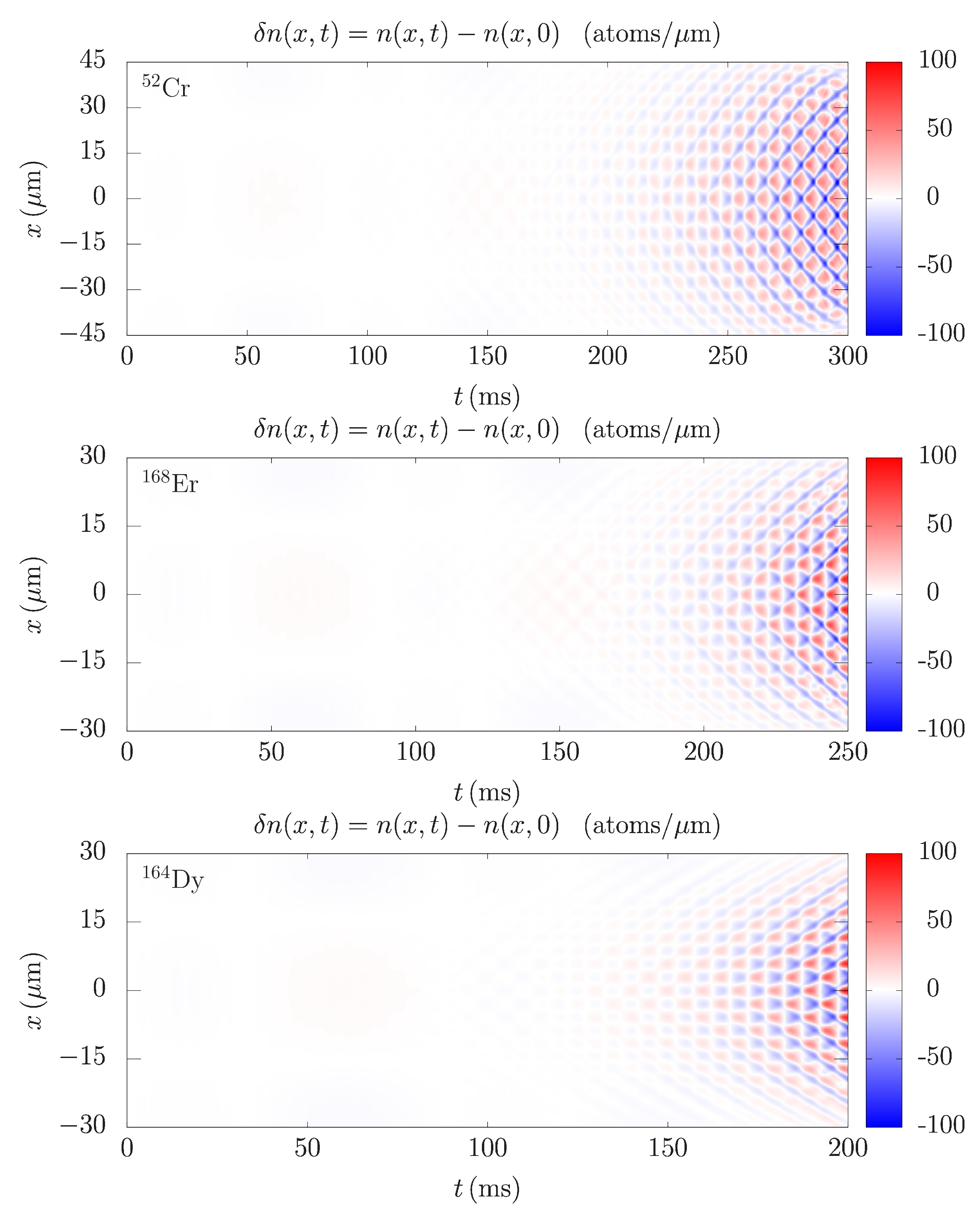
Figure 1 shows time dependence of the integrated density profile variations in the weak confinement direction
. Here,
is the column density profile calculated by integrating the 3D condensate density
over the radial coordinates
y and
z.
The emergence of spatial patterns is clearly visible for all three atomic species after around 150 ms. This is consistent with earlier experimental observations [
12,
13,
14] and theoretical results [
16,
24,
25]. The density waves in
x direction from
Figure 1 take time to develop and are a result of the transfer of energy from the modes that are directly excited in the radial directions, where the trap is modulated. On the other hand, the density waves in the radial directions (which are not shown here) emerge immediately after the modulation is switched on at
, and their frequency is equal to the modulation frequency. By looking at
Figure 1, we can even estimate the main oscillation frequency, e.g., counting the number of maxima or minima in a given time interval. For instance, in the last 50 ms in each of the panels in
Figure 1, we count five periods, which corresponds to the frequency
. This is a distinguishing characteristic of Faraday waves, and therefore we can directly determine that in this case the system develops this type of collective oscillations.
However, this way we can determine only the main excitation modes. The dynamics of the system contains other modes as well, and over the time they can develop and even start to dominate the behavior of the system. Therefore, it is important to analyze the spectra in more detail. This is done in
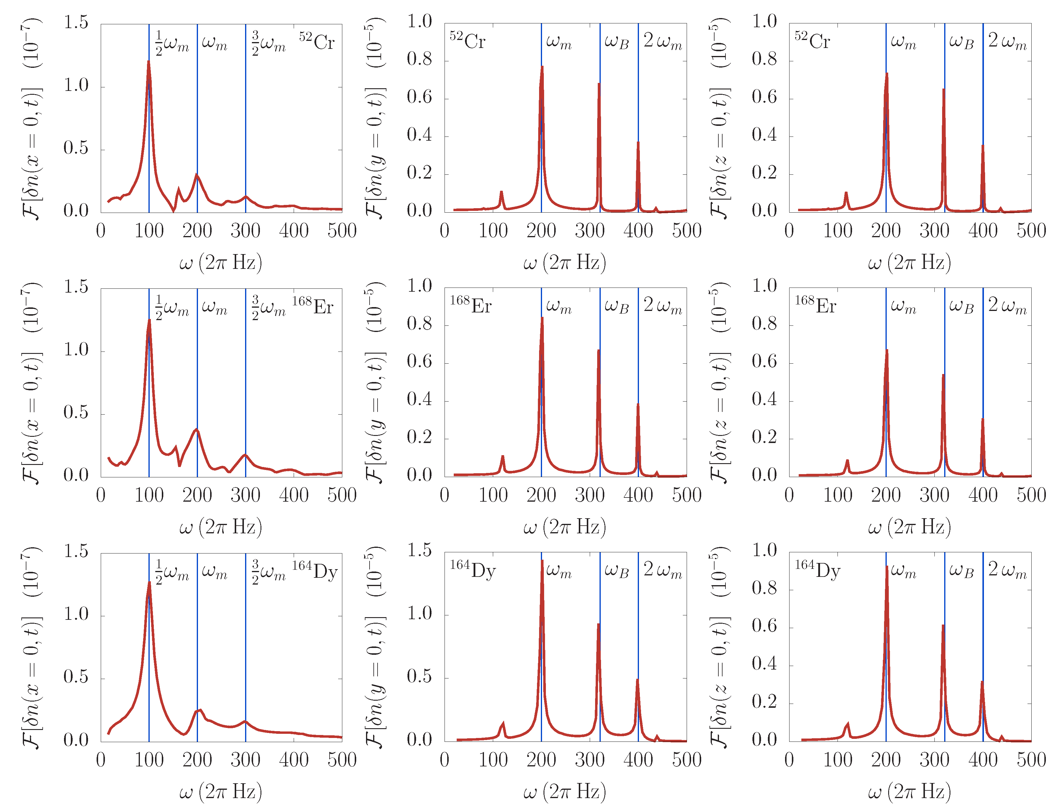
Figure 2 for all integrated density profile variations, separately for each spatial direction. For simplicity, the FFT analysis is performed for the profiles at the trap center. As expected, in the weak confinement direction (left column of
Figure 2), the main excitation mode has a frequency
. In addition to this, we observe two other modes, at
and
. This is expected from the theoretical analysis in
Section 2, but could not be discerned directly from the density profiles or their variations.
In the Fourier spectra of the integrated density profile variations in the radial directions (middle and right columns of
Figure 2), we see a somewhat richer set of excitation modes. In addition to the main mode corresponding to the trap modulation at
, we see that also the breathing mode is excited at the frequency
Hz. This value can be calculated by linearizing the equations of motion from
Section 2. The spectra prominently contain the second modulation harmonic at
as well. We also see some other peaks, for instance the small peak at around
Hz, which can be due to the linear combination of the modes
. However, such an identification would require further theoretical and numerical analysis, which is out of the scope of the present paper.
While the Fourier analysis in the time-frequency domain can be used to determine the character of the induced density waves (Faraday, collective, and resonant), the analysis in the spatial-frequency domain enables us to characterize the density patterns and calculate their spatial period. This is illustrated in
Figure 3 for Faraday waves for all three considered atomic species. The integrated density profile variations are analyzed at appropriate times, which are determined to correspond to the evolution stage when Faraday waves have fully emerged, but the system is still far from the violent dynamics that inevitably follows after the long driving period.
In all three panels of
Figure 3, the main peak corresponds to the wave vector
of the Faraday waves, and we see significant differences: for
Cr, we obtained
, yielding the spatial period
; for
Er, we obtained
and
; and, for
Dy, we obtained
and
. The variational analysis presented in
Section 2 yields results which are in good agreement with the numerical ones, namely
for
Cr,
for
Er, and
for
Dy. These variational results are shown in
Figure 3 by vertical blue lines, which illustrate their agreement with the Fourier analysis. The presented spectra also contain some additional peaks that correspond to other geometrical features of the analyzed density profile variations, such as the condensate widths and their higher harmonics, as well as the higher harmonics of the Faraday waves periods, and linear combinations of all of these. However, they are not of interest for our analysis and we did not study them further.
Note that the spatial period of Faraday waves can also be determined by directly looking at the density profile variations in
Figure 1, and estimating the spacing between the consecutive minima or maxima at the appropriate evolution time. For instance, for chromium, we count three minima over the spatial extent of 30
m, yielding an estimate
, and similarly for other species. Obviously, such estimates are not as precise as the Fourier analysis results, and therefore we rely on FFT spectra to systematically determine the spatial periods of Faraday waves and their functional dependencies on the contact and the DDI strength.
4. Interaction Effects and Properties of Faraday Waves
In the previous section, we show how the Fourier analysis can be used to calculate the spatial period of Faraday waves. Next, we systematically studied the interaction effects, namely how the contact and the DDI strength affect the properties of generated density waves. First, we explored the influence of the contact interaction on the emergence time and the spatial period of Faraday waves for a fixed value of the DDI strength. In experiments, this can be achieved by employing the Feshbach resonance technique, which allows tuning by changing the external magnetic field, thus changing the electronic structure of atoms and their scattering properties.
The existence of Faraday waves is a consequence of nonlinearity of the system, i.e., the presence of the contact and the DDI terms in the Hamiltonian. In a linear system, described by the pure Schrödinger equation, the harmonic modulation of the trap in the radial direction would not be transferred into the longitudinal direction. Therefore, the emergence time of Faraday waves (and other types of density waves in the longitudinal direction) critically depends on the strength of interatomic interactions. However, if interaction strengths become sufficiently large, the emergence time is less sensitive to their changes. Since the DDI is strong in erbium and dysprosium, we can expect that the emergence time of Faraday waves significantly depends on the contact interaction strength only in chromium, where is small.
This is illustrated in
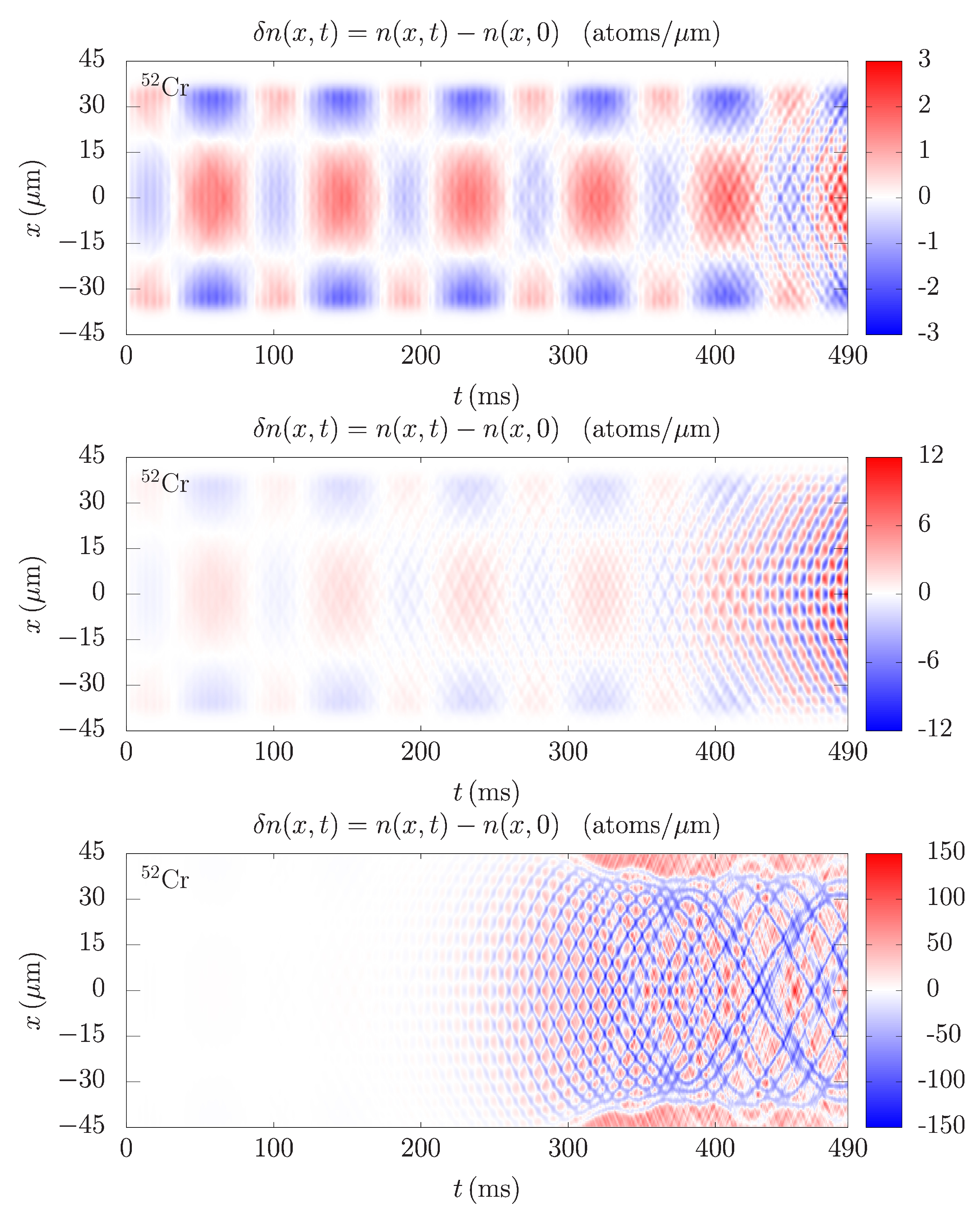
Figure 4, where we see the density profile variations for chromium for three different values of
. Let us first note that the amplitude of density variations is much smaller in the top panel for
than in the middle panel for
, and significantly smaller than in the bottom panel for
. This is also evident from the fact that in the top and middle panel we can clearly see the quadrupole collective oscillation mode, which has a frequency of around
Hz. This can be estimated from the figure and compared to the variational value of
, which can be obtained by linearizing the equations of motion in
Section 2. When the interaction is sufficiently large, the amplitude of Faraday waves is much larger than those of the collective modes, and they cannot be even discerned in the bottom panel in
Figure 4. Only for a weak interaction the amplitude of the Faraday waves is comparable to the amplitude of the collective modes, and this is why we can see them all for small values of
.
As with all other excitations, Faraday waves start to develop immediately after the modulation is switched on. The question on their emergence time is related to their amplitude, which is time-dependent and grows exponentially, as can be seen from the solution (Equation (
18)) of the Mathieu-like equation that describes the dynamics of the Faraday density oscillations. The imaginary part of the parameter
in Equation (
18) is responsible for the exponential growth of the Faraday waves’ amplitude, which is not the case for collective modes. Therefore, in practical terms, the definition of the emergence time of Faraday waves is always arbitrary and can be expressed as a time needed for the density variations to reach a certain absolute or relative (compared to the total density) value. One can even relate this to the experimental point of view, where there is a threshold for the density variations that can be observed, due to measurement errors. However, in numerical simulations, there are no such limitations and one can easily use an arbitrary definition to estimate the emergence time of density waves. The more relevant quantity to study would be the exponent that governs the growth of the wave amplitude, which depends on the interaction strength.
Now, we turn our attention to spatial features of the Faraday waves.
Figure 5 presents the dependence of the wave vector
on the
s-wave scattering length
for all three considered species. We also show the variational results for the dependence
derived in
Section 2. The agreement is very good, with errors of the order of 10–15%. We stress that the derived variational expression closely follows the numerical results not only by their values, but, more importantly, also their functional dependence properly.
Next, we studied the effects of the DDI strength for a fixed value of the contact interaction.
Figure 6 shows the corresponding dependence of
on
. In contrast to the contact interaction dependence, where
is a decreasing function of
, here we see that
increases as the DDI strength is increased.
Figure 6 also shows the variational results, where the level of agreement with the numerically obtained results is different, with errors as small as 7% for chromium and up to around 25% for erbium and dysprosium for largest values of
. Due to complex approximations made in the derivation of variational results, in particular those related to the DDI term, the obtained functional dependence is not as good as in the case of contact interaction, but still provides reasonable estimates of the wave vector values for the Faraday waves.
5. Resonant Waves
In the presence of interactions, various excitation modes in dipolar BECs are coupled and the energy pumped into the system by periodic driving can be transferred from the driving direction to other, orthogonal directions. In the previous section, we show this for non-resonant driving, when the harmonic modulation in the radial direction was transferred to the longitudinal direction in the form of Faraday waves, which were the main excitation mode generated. The main distinguishing property of these excitations is halving of the oscillation frequency, i.e., the induced density waves have the frequency . Next, we studied the other important case, when the modulation frequency is resonant, such that the induced density waves have the same frequency. This happens when is close to one of the characteristic frequencies of the system, e.g., one of the frequencies of the collective oscillation modes or one of the trap frequencies. Although Faraday waves and all other collective oscillation modes are also excited in this case, the largest amplitude corresponds to resonant waves with the frequency . When generated, these resonant waves dominate the behavior of the system and make all other excitations negligible for the dynamics.
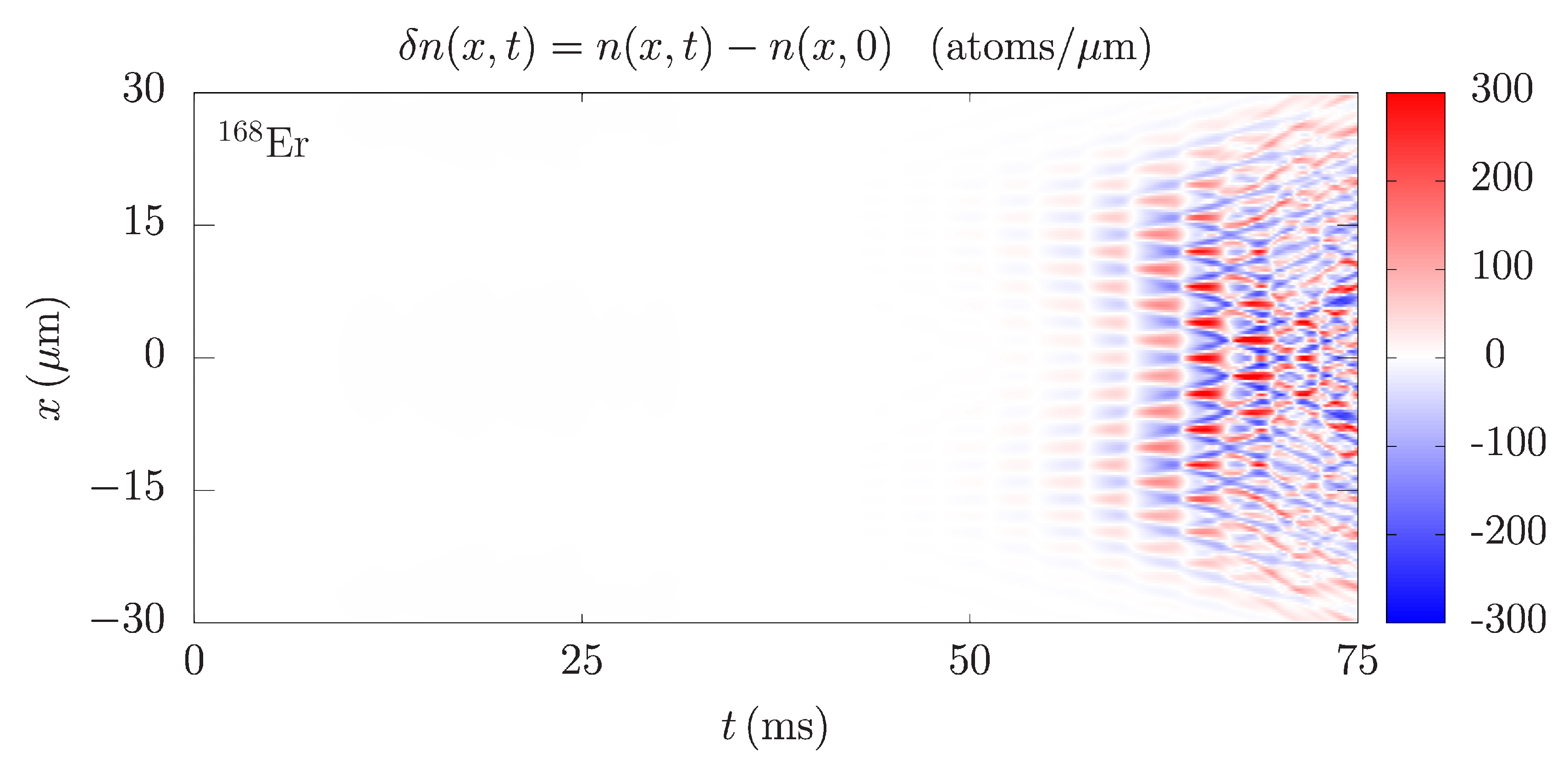
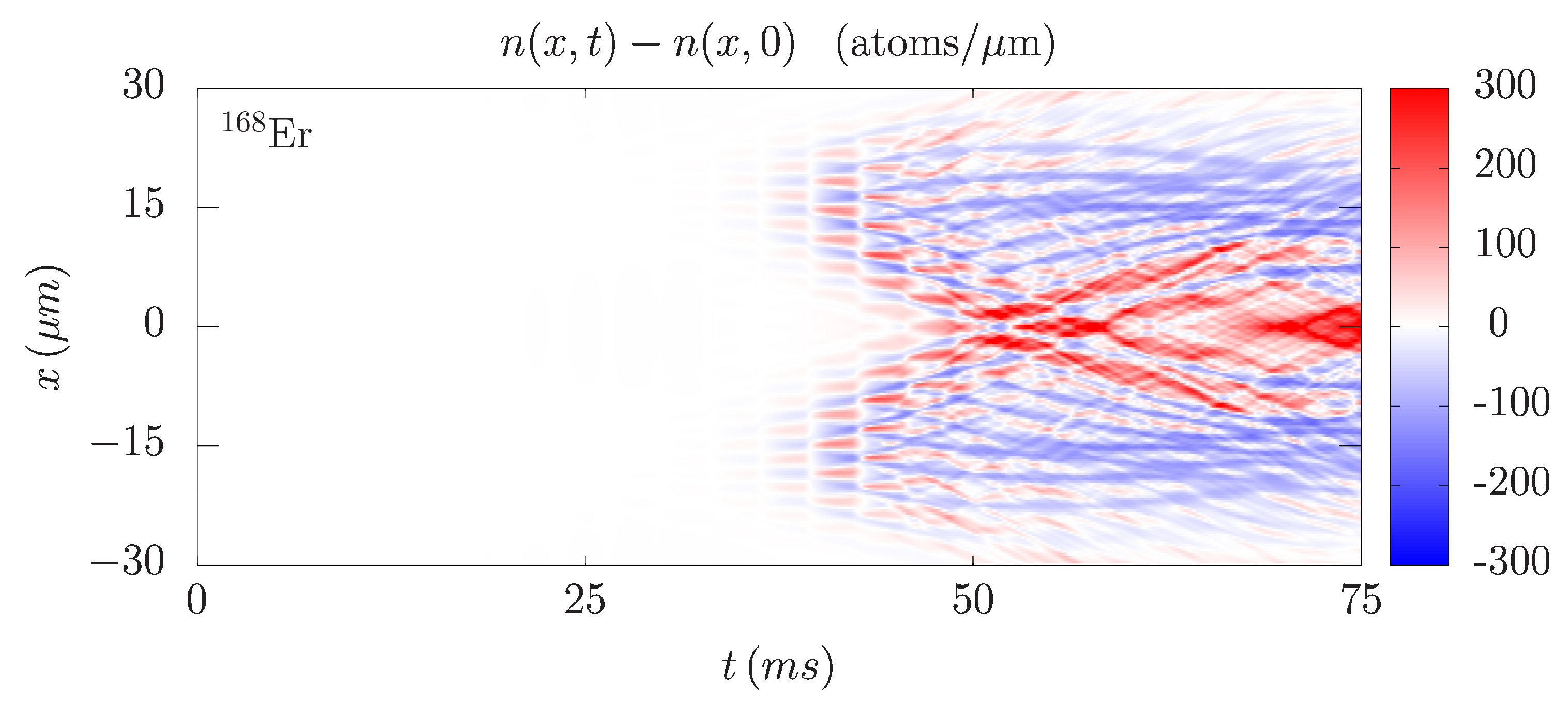
Figure 7 shows the integrated density profile variation of
Er for a resonant wave induced by a harmonic modulation of the radial part of the trapping potential at
, i.e., when the modulation frequency coincides with the radial trapping frequency. The density waves in this case develop much more quickly than for the non-resonant modulation and are clearly visible already after 55 ms. Due to a violent dynamics that emerges in the system very quickly, it is not easy to estimate the frequency of the waves directly from
Figure 7, as was possible before. Therefore, we relied on the Fourier analysis in the time-frequency domain, as presented in the left panel of
Figure 8. The obtained FFT spectrum clearly shows that the main excitation mode has the frequency equal to
. We also see that the spectrum is continuous, practically without distinct individual peaks, and only the second harmonic at
yields a small local maximum. This demonstrates that the system is far from the regime of small perturbations, where individual excitation modes can be observed.
In the right panel of
Figure 8, we see the Fourier spectrum in the spatial-frequency domain, which yields the wave factor
of resonant waves. The FFT results give the value
and the corresponding spatial period
for
Er. In the figure we also present the variational result
, calculated using Equation (
24). The agreement is again quite good, which indicates that the variational approach developed in this paper can be reliably used not only for the Faraday waves, but also for the resonant waves.
This can also be concluded from
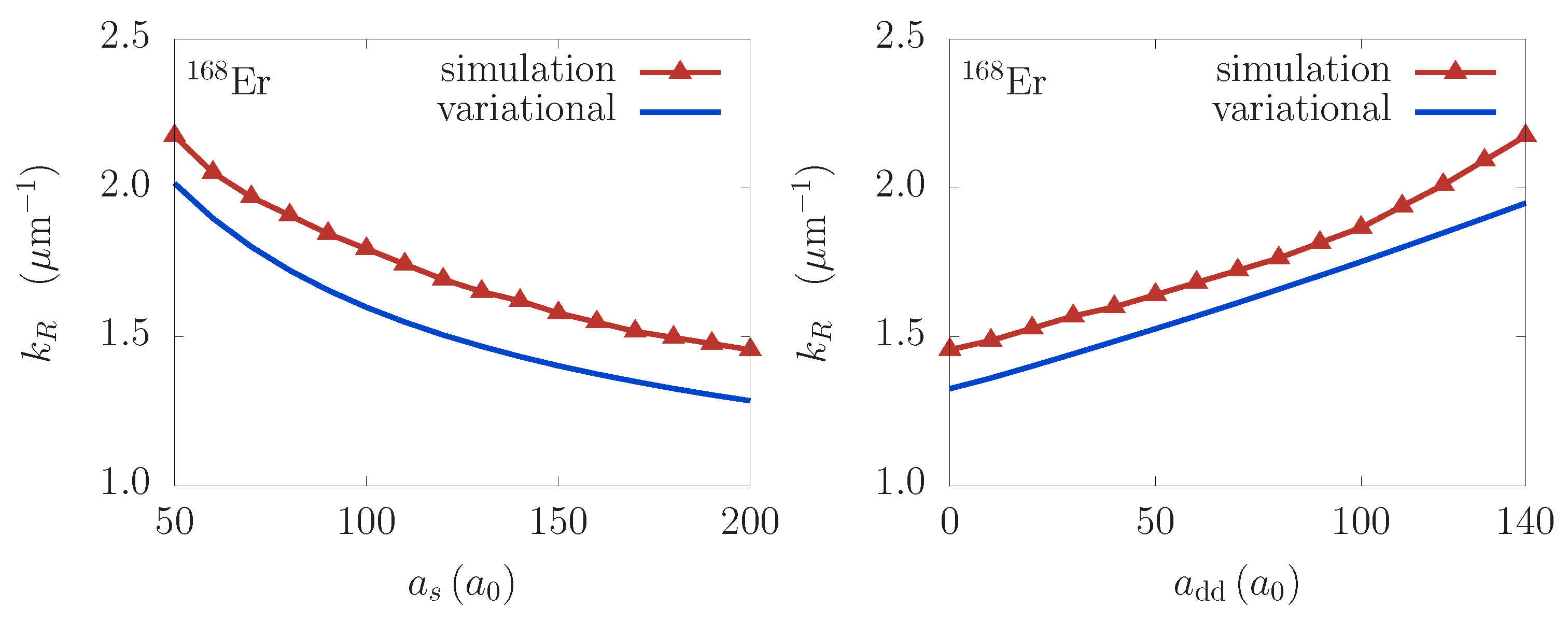
Figure 9, which presents the results for the dependence of the resonant wave vector
on the contact and the DDI strength. The agreement between the numerical and variational results is of the order of 10% over the whole experimentally relevant domain. We see similar behavior for the resonant waves as for the Faraday ones, namely the wave vector decreases as the contact interaction strength increases, while the opposite is true for the DDI. Again, the functional dependence obtained from the variational approach properly describes the numerical results, thus confirming that Equation (
24) can be used to calculate spatial period of resonant waves.
It is interesting to note that resonant behavior appears not only under conditions mentioned above, when
is equal to one of the characteristic frequencies, but also when it matches their higher harmonics.
Figure 10 illustrates this for
Er, which is harmonically modulated at twice the radial trapping frequency,
Hz. In this case, the amplitude of the resonant mode grows even more quickly and significant density variations can be observed already after 30 ms. Therefore, we see that the modulation at the second harmonic yields even more violent dynamics than the first harmonic. The Fourier analysis in the time-frequency domain reveals that the main excitation mode again has a frequency of
, but the mode at
is also present. From the experimental point of view, resonant driving is very dangerous and leads to the destruction of the system in a matter of tens of milliseconds. While numerical simulations can be performed for longer time periods, the atoms leave the condensate due to a large, resonant transfer of energy to the system. As the condensate is depleted, the mean-field description of the system breaks down and it can no longer be simulated by the dipolar Gross-Pitaevskii equation.
