Influence of Loose Contact between Tunnel Lining and Surrounding Rock on the Safety of the Tunnel Structure

Abstract
:1. Introduction
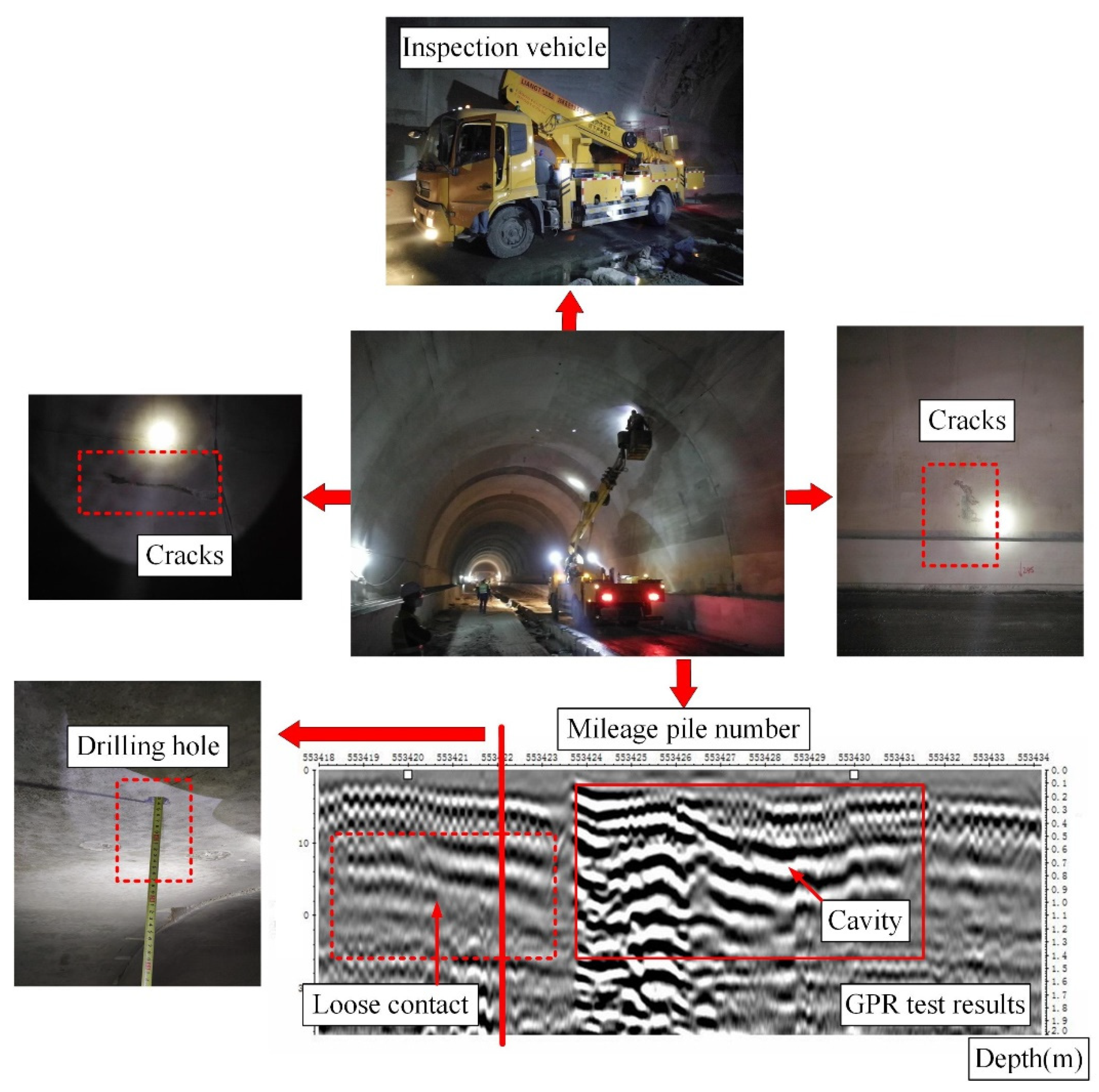
2. Field Investigation
3. Numerical Simulation and Model Test Verification
3.1. Numerical Model
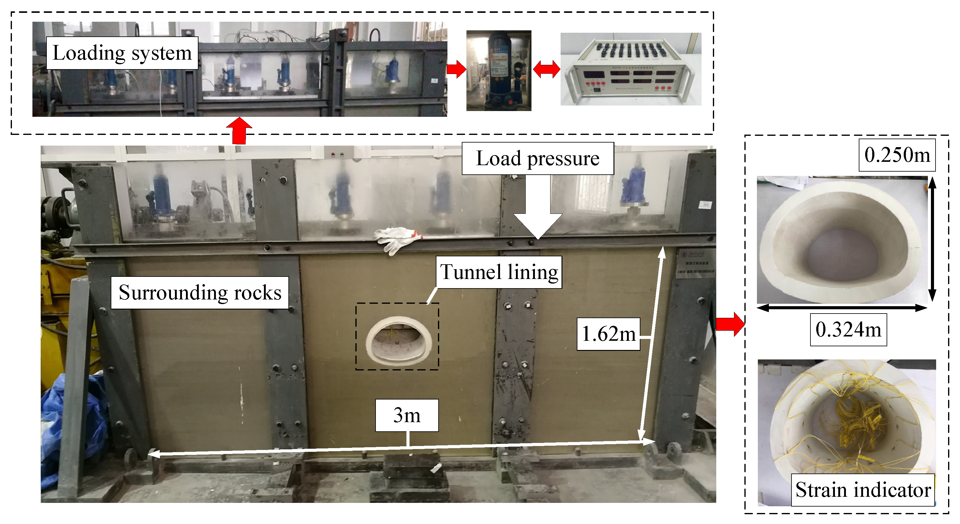
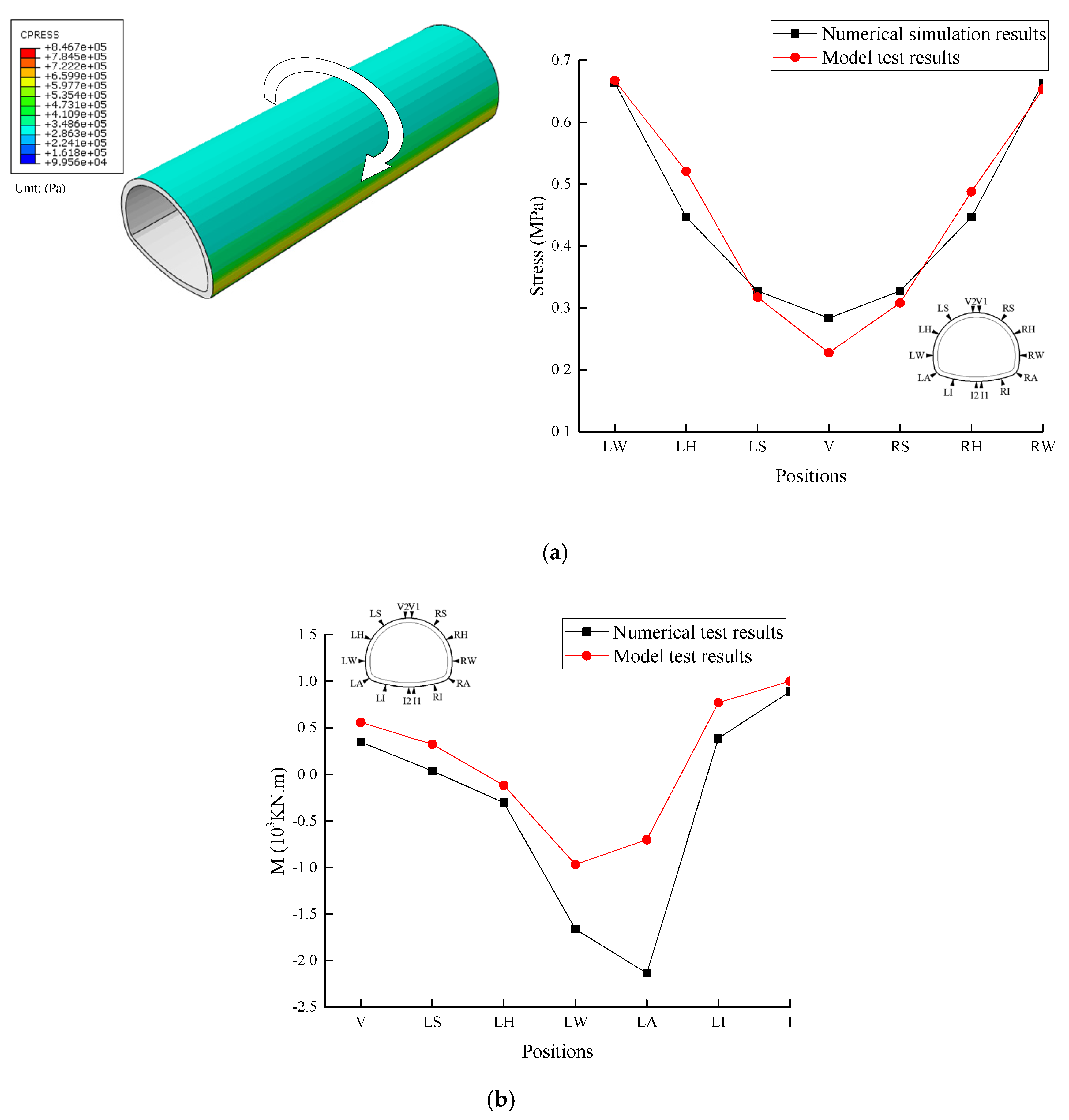
3.2. Model Test Verification
3.3. Simulation Cases
4. Influence of Insufficient Compactness behind Tunnel Lining
4.1. Effect of the Compactness
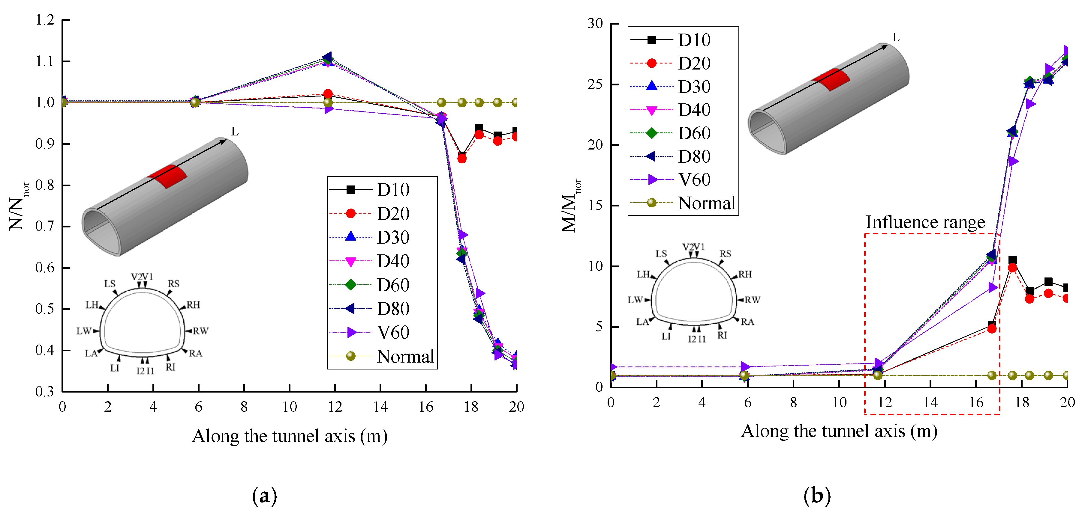
4.1.1. Changes in the Internal Force
4.1.2. Changes in the Contact Pressure
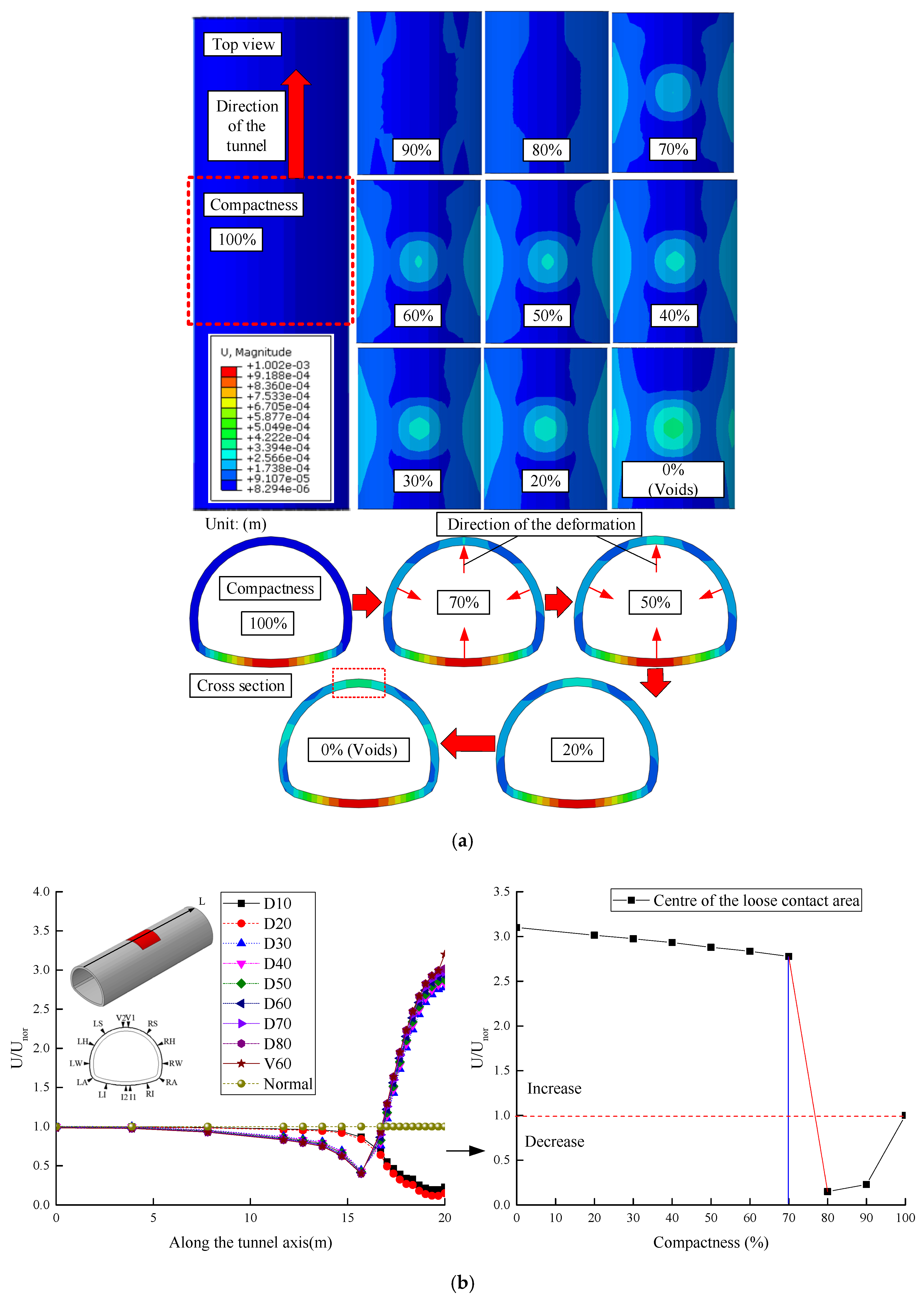
4.1.3. Changes in the Deformation
4.2. Effect of the Loose Contact Area
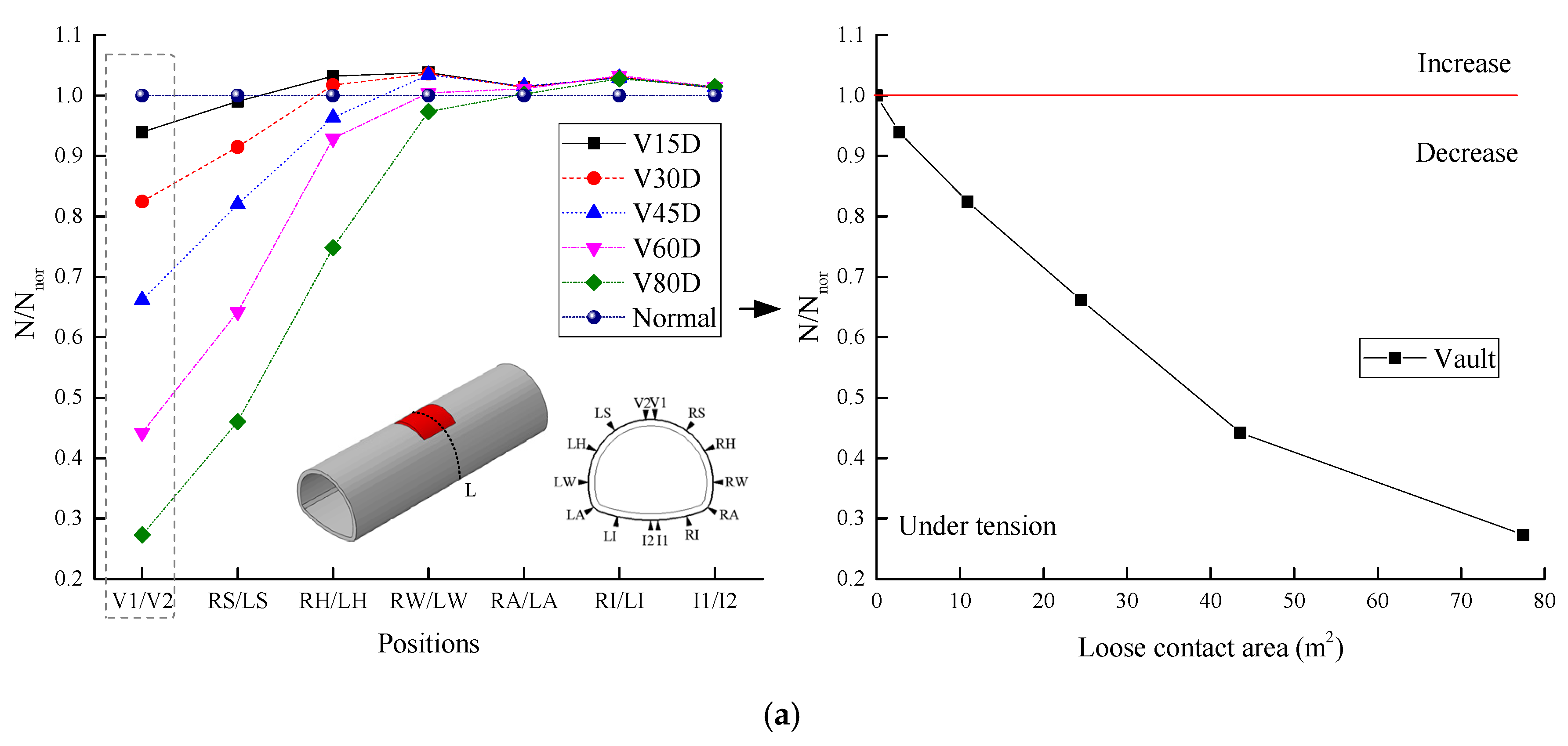
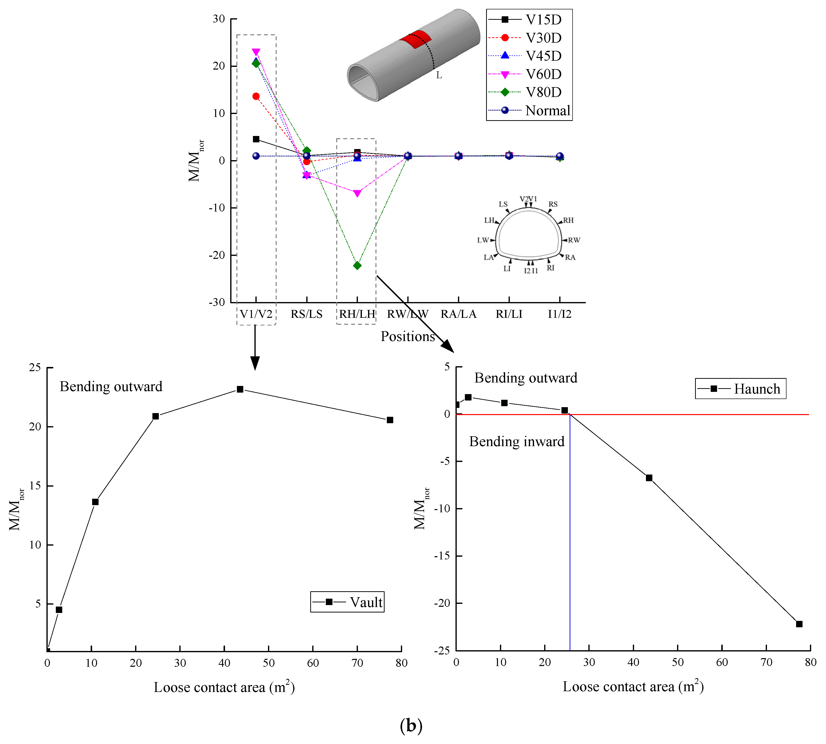
4.2.1. Changes in the Internal Force
4.2.2. Changes in the Contact Pressure
4.2.3. Changes in the Deformation
5. Influence of Insufficient Strength behind Tunnel Lining
5.1. Variation of the Internal Force
5.2. Variation of the Contact Pressure
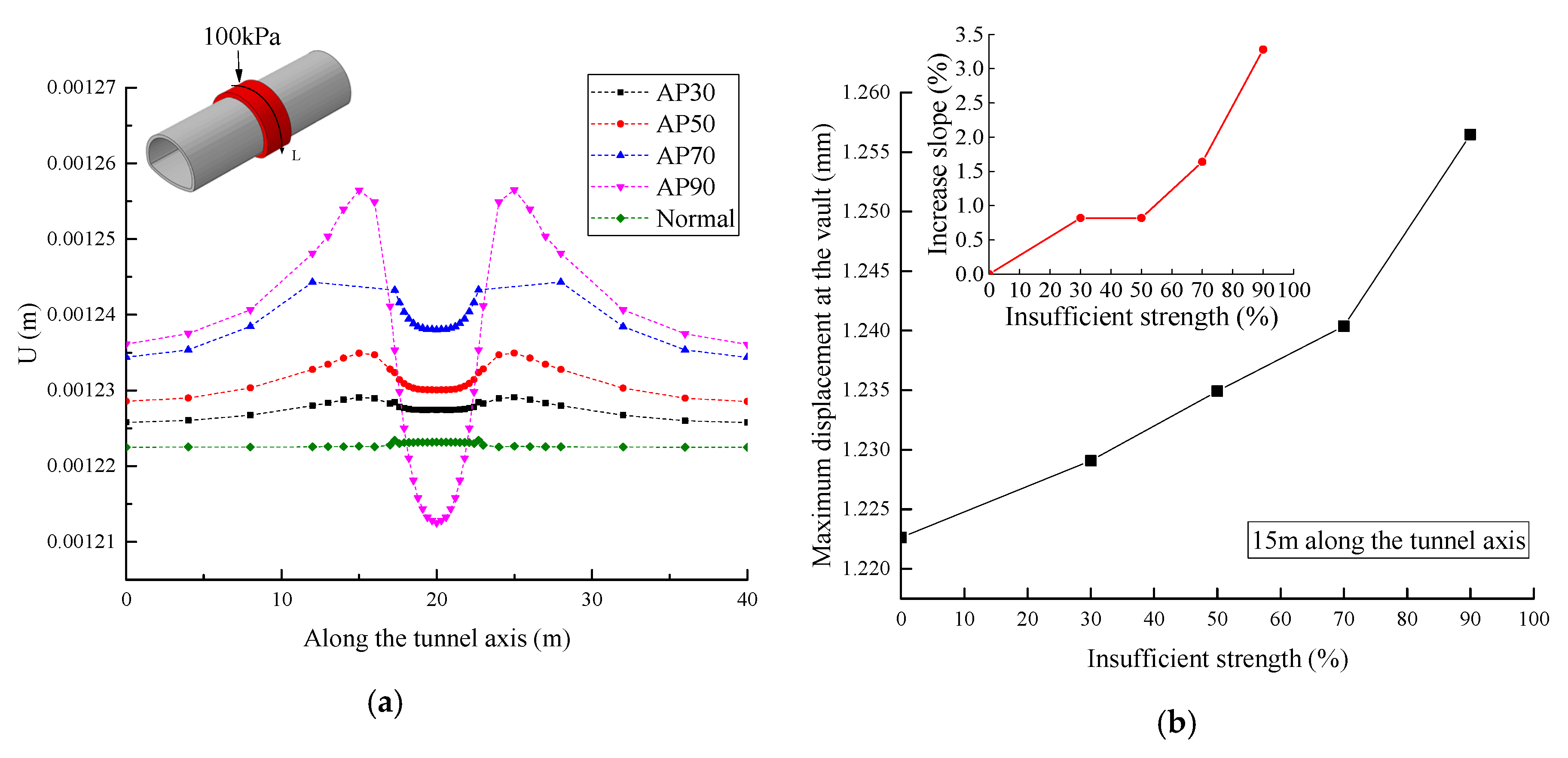
5.3. Variation of the Deformation
6. Grade Classification of the Lining Structure Safety Influenced by Loose Contact behind Lining
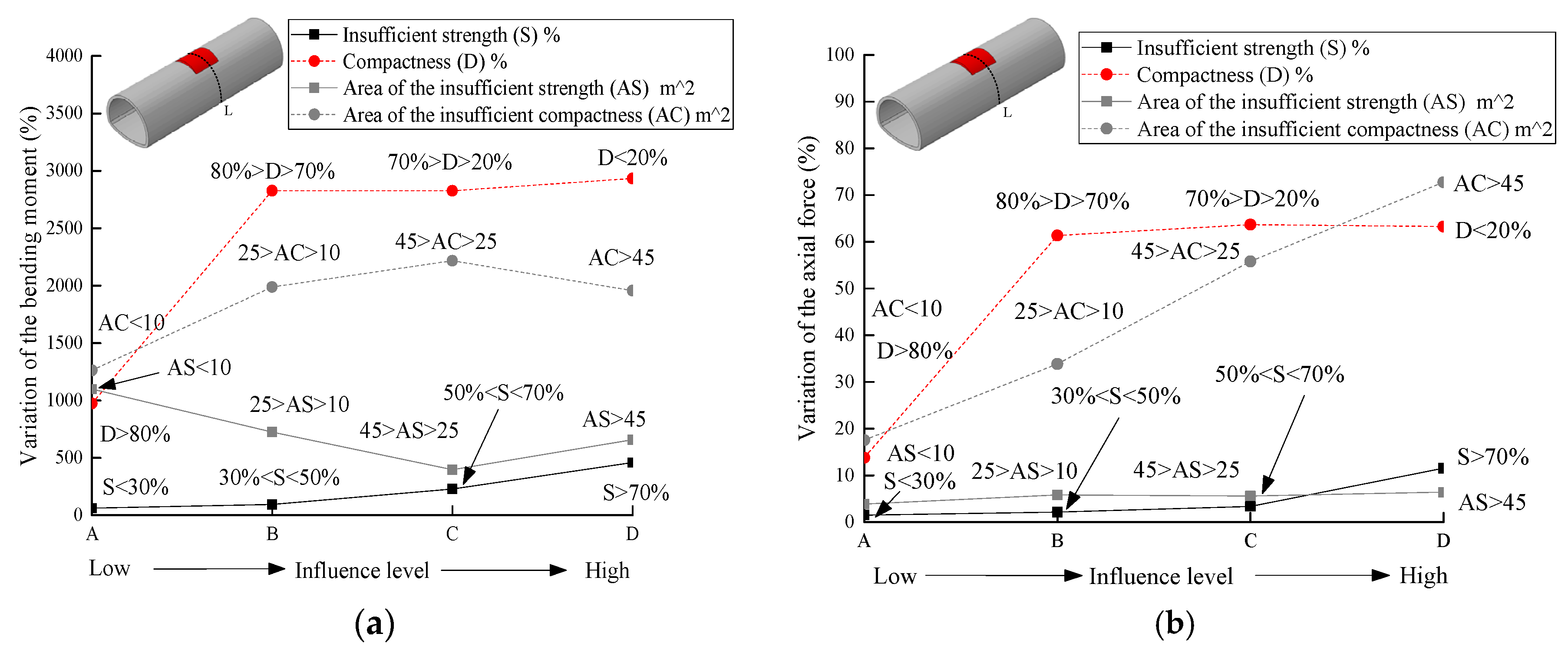
6.1. Comparison of the Influence of Internal Force and Safety Factor
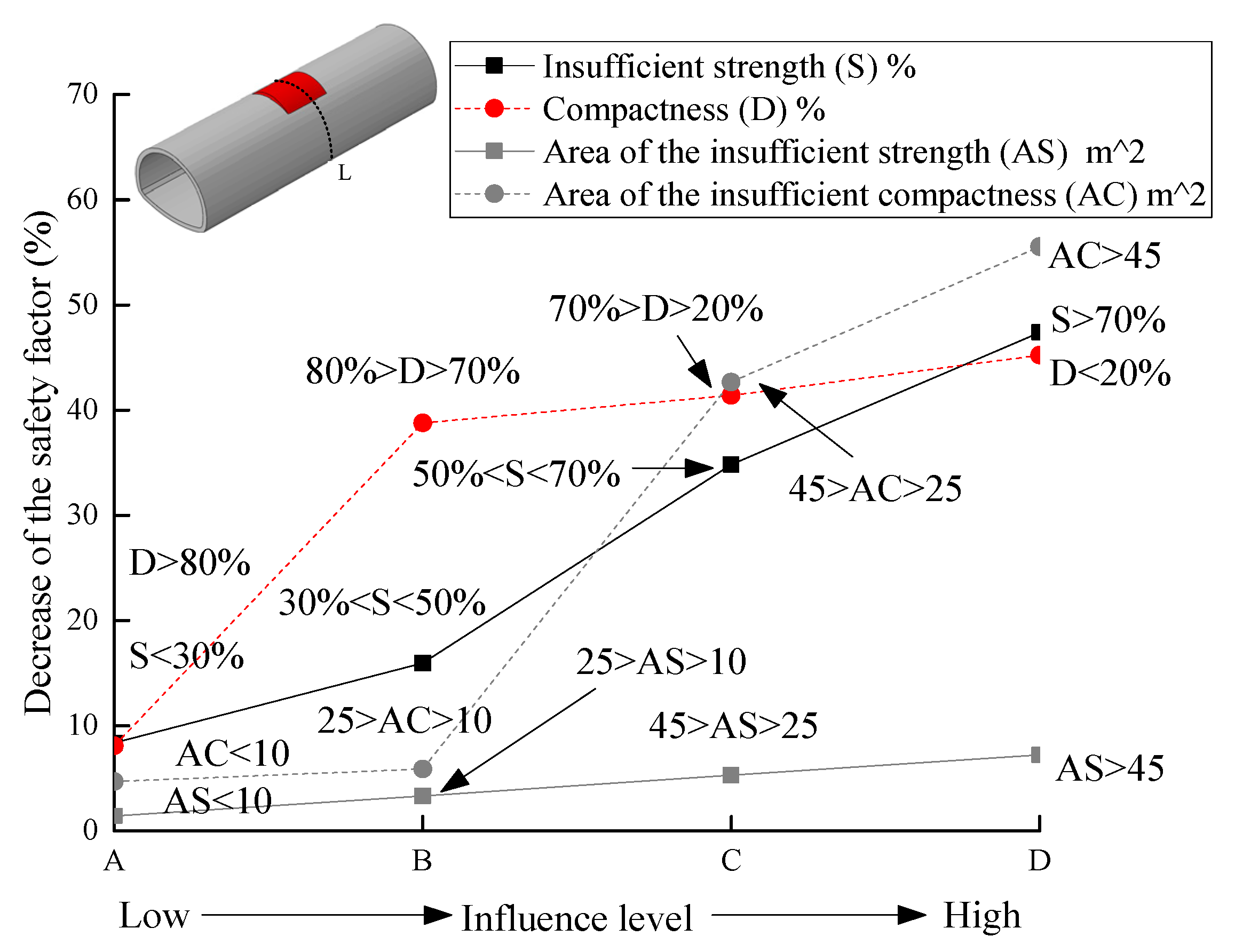
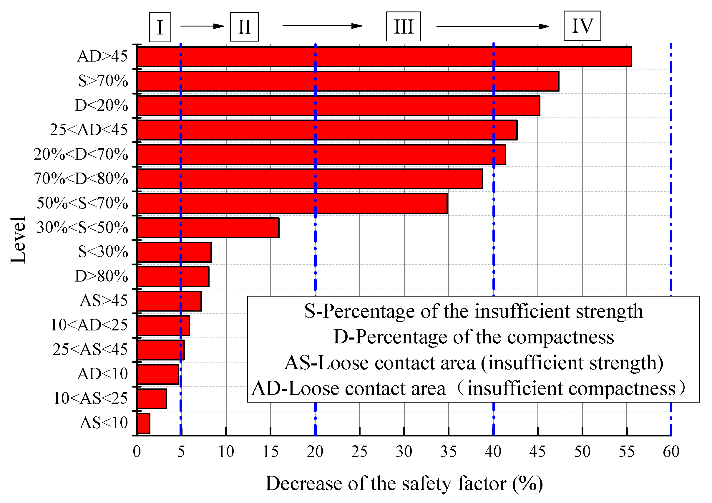
6.2. Grade Classification
7. Conclusions
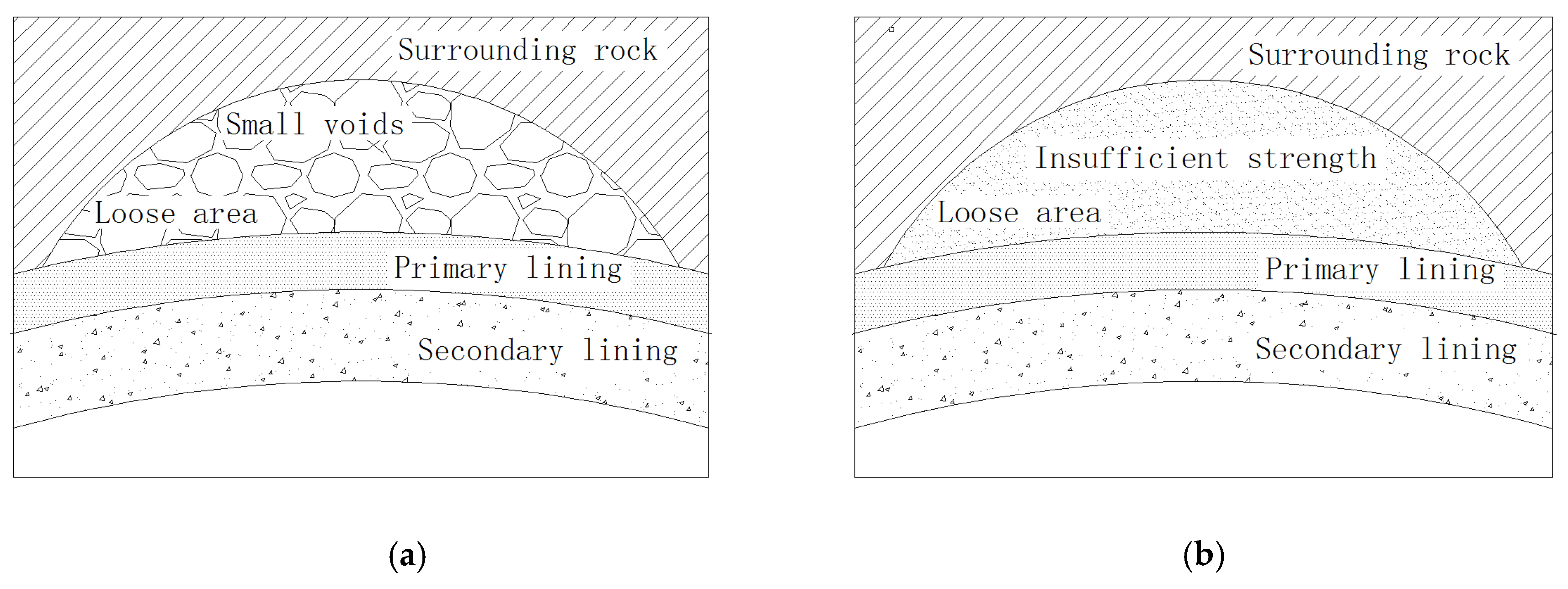
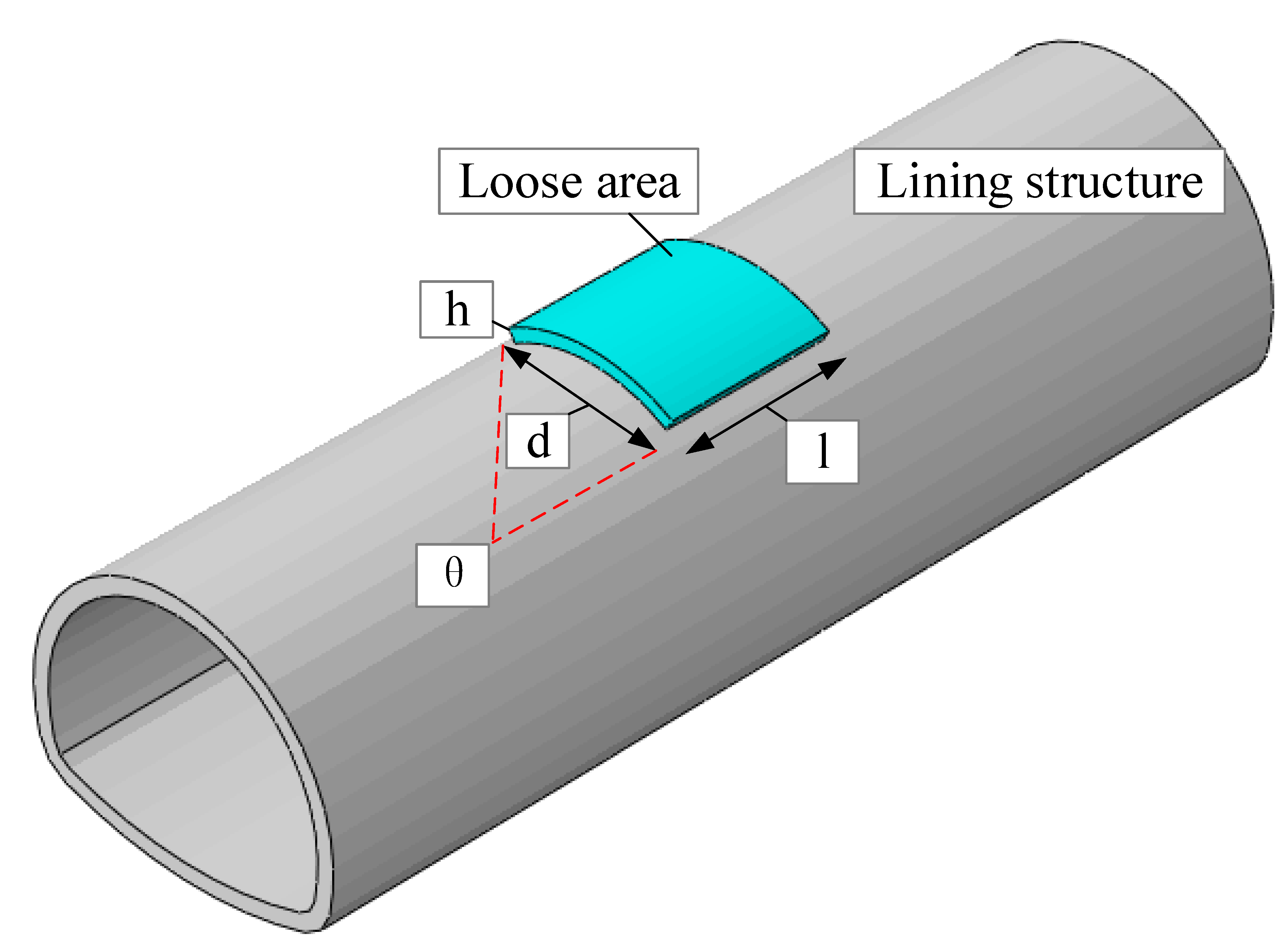
- The influence factor of loose contact states behind lining can be divided into two categories based on the cause analysis in the field investigation: one was the compactness, another one was the insufficient strength parameters. The compactness in the loose contact area behind lining should be above 70%. To strictly prevent unwilling deformation of the lining structure and cracks, it was recommended that the compactness should be above 80% after back-fill grouting. Meanwhile, the range of the loose contact area should be no more than 60 degree, otherwise the contact pressure and the vertical displacement of the lining structure at the vault were increased by multiple times.
- The influence of the insufficient strength in the loose contact area behind lining on the lining structure safety was mainly concentrated within the loose contact region of the structure. The strength of the back-fill grouting behind lining should be above 50% strength of the surrounding rock, otherwise the safety of the lining structure will be extremely harmed, especially when the range of the loose area was increased, and the tunnel lining was gradually surrounded. Therefore, the strength of the back-fill grouting behind lining should be ensured. The loose contact area was developed and connected with each other, which should be avoided.
- The influence of the compactness of the loose contact area on the safety of tunnel lining was greater than the influence of the strength. The impact on the safety increased with the area of the loose contact behind lining. The classification of the influence grade of loose contact on the safety of the lining structure not only provided scientific instruction to control the quality of the back-fill grouting properly, but also offered a valuable reference for the evaluation of the contact state between lining and surrounding rock.
Author Contributions
Funding
Conflicts of Interest
References
- Ministry of Transport. Statistical Bulletin on the Development of the Transport Industry in 2019. Tunn. Constr. 2020, 40, 820. [Google Scholar]
- Wang, J.; Huang, H.; Xie, X.; Bobet, A. Void-induced liner deformation and stress redistribution. Tunn. Undergr. Space Technol. 2014, 40, 263–276. [Google Scholar] [CrossRef]
- Yan, Q.; Xu, Y.; Zhang, W.; Geng, P.; Yang, W. Numerical analysis of the cracking and failure behaviors of segmental lining structure of an underwater shield tunnel subjected to a derailed high-speed train impact. Tunn. Undergr. Space Technol. 2018, 72, 41–54. [Google Scholar] [CrossRef]
- Zhao, Y.; Liu, C.; Zhang, Y.; Yang, J.; Feng, T. Damaging behavior investigation of an operational tunnel structure induced by cavities around surrounding rocks. Eng. Fail. Anal. 2019, 99, 203–209. [Google Scholar] [CrossRef]
- Zhang, Y.; Shi, Y.; Zhao, Y.; Yang, J. Damage in concrete lining of an operational tunnel. J. Perform. Constr. Facil. 2017, 31, 06017002. [Google Scholar] [CrossRef]
- Feng, H.; Zhang, X.; Gou, D.; Chun, J.; Ou, X.; Zhou, X. Cause investigation of side-wall cracking in an operational tunnel. Eng. Fail. Anal. 2019, 101, 157–171. [Google Scholar] [CrossRef]
- Xiao, J.; Dai, F.; Wei, Y.; Min, H.; Xu, C.; Tu, X.; Wang, M. Cracking mechanism of secondary lining for a shallow and asymmetrically-loaded tunnel in loose deposits. Tunn. Undergr. Space Technol. 2014, 43, 232–240. [Google Scholar] [CrossRef]
- Jane, M.P.; David, C.; Ian, D.M.; Neil, H. Impact of soil erosion voids on reinforced concrete pipe responses to surface loads. Tunn. Undergr. Space Technol. 2018, 82, 111–124. [Google Scholar]
- Do, N.A.; Oreste, P.; Dias, D.; Antonello, C.; Djeran-Maigre, I.; Livio, L. Stress and strain state in the segmental linings during mechanized tunnelling. Geomech. Eng. 2014, 7, 75–85. [Google Scholar] [CrossRef]
- Zhang, X.; Zhang, C.; Min, B.; Xu, Y. Experimental study on the mechanical response and failure behavior of double-arch tunnels with cavities behind the liner. Geomech. Eng. 2020, 20, 399–410. [Google Scholar]
- Meguid, M.A.; Dang, H.K. The effect of erosion voids on existing tunnel linings. Tunn. Undergr. Space Technol. 2009, 24, 278–286. [Google Scholar] [CrossRef]
- Zhang, X.; Ye, Z.; Min, B.; Xu, Y. Effect of voids behind lining on the failure behavior of symmetrical double-arch tunnels. Symmetry 2019, 11, 1321. [Google Scholar] [CrossRef] [Green Version]
- Yasuda, N.; Tsukada, K.; Asakura, T. Elastic solutions for circular tunnel with void behind lining. Tunn. Undergr. Space Technol. 2017, 70, 247–285. [Google Scholar] [CrossRef]
- Fu, J.; Xie, J.; Wang, S.; Yang, J.; Yang, F.; Pu, H. Cracking performance of an operational tunnel lining due to local construction defects. Int. J. Geomech. 2019, 19, 04019019. [Google Scholar] [CrossRef]
- Sedarat, H.; Kozak, A.; Hashash, Y.; Shamsabadi, K. Contact interface in seismic analysis of circular tunnels. Tunn. Undergr. Space Technol. 2009, 24, 482–490. [Google Scholar] [CrossRef]
- Meguid, M.A.; Kamel, S. A three-dimensional analysis of the effects of erosion voids on rigid pipes. Tunn. Undergr. Space Technol. 2014, 43, 276–289. [Google Scholar] [CrossRef]
- Chen, Z.; Jia, P. Three-dimensional analysis of effects of ground loss on static and seismic response of shafts. Tunn. Undergr. Space Technol. 2019, 92, 103067. [Google Scholar] [CrossRef]
- Yasuda, N.; Tsukada, K.; Asakura, T. Three-dimensional seismic response of a cylindrical tunnel with voids behind the lining. Tunn. Undergr. Space Technol. 2019, 84, 399–412. [Google Scholar] [CrossRef]
- Li, Y.; Luo, R.; Zhang, Q.; Xiao, G.; Zhou, L.; Zhang, Y. Model test and numerical simulation on the bearing mechanism of tunnel-type anchorage. Geomech. Eng. 2017, 12, 139–160. [Google Scholar] [CrossRef]
- Zhang, X.; Zhang, C.; Feng, G.; Han, K. Experimental studies on effect of voids behind tunnel linings on progressive failure process of tunnel structures. Chin. J. Geotech. Eng. 2017, 39, 1137–1144. [Google Scholar]
- Leung, C.; Meguid, M.A. An experimental study of the effect of local contact loss on the earth pressure distribution on existing tunnel linings. Tunn. Undergr. Space Technol. 2011, 26, 139–145. [Google Scholar] [CrossRef]
- Ye, Z.; Zhang, C.; Ye, Y. Model test of detection of contact status behind shield tunnel segment using the transient electromagnetic radar. J. China Railw. Soc. 2019, 41, 121–131. [Google Scholar]
- Ye, Z.; Ye, Y. Comparison of detection effect of cavities behind shield tunnel segment using transient electromagnetic radar and ground penetration radar. Geotech. Geol. Eng. 2019, 37, 4391–4403. [Google Scholar] [CrossRef]
- Lai, W.W.L.; Derobert, X.; Annan, P. A review of ground penetrating radar application in civil engineering: A 30-year journey from locating and testing to imaging and diagnosis. NDT E Int. 2018, 96, 58–78. [Google Scholar]
- Ye, Z.; Zhang, C.; Ye, Y.; Zhu, W. Application of transient electromagnetic radar in quality evaluation of tunnel composite lining. Constr. Build. Mater. 2020, 240, 117958. [Google Scholar] [CrossRef]
- Kravitz, B.; Mooney, M.; Karlovsek, J.; Danielson, I.; Hedayat, A. Void detection in two-component annulus grout behind a pre-cast segmental tunnel liner using ground penetrating radar. Tunn. Undergr. Space Technol. 2019, 83, 381–392. [Google Scholar] [CrossRef]
- Ye, Z.; Ye, Y.; Zhang, C. Transient electromagnetic effect of the underdamped center loop. Prog. Geophys. 2019, 34, 2106–2111. [Google Scholar]
- Li, W.; Zhang, C. Face stability analysis for a shield tunnel in anisotropic sands. Int. J. Geomech. 2020, 20, 04020043. [Google Scholar] [CrossRef]
- Li, W.; Zhang, C.; Zhu, W.; Zhang, D. Upper-bound solutions for the face stability of a non-circular NATM tunnel in clays with a linearly increasing undrained shear strength with depth. Comput. Geotech. 2019, 114, 103136. [Google Scholar] [CrossRef]
- Zhang, C.; Li, W.; Zhu, W.; Tan, Z. Face stability analysis of a shallow horseshoe-shaped shield tunnel in clay with a linearly increasing shear strength with depth. Tunn. Undergr. Space Technol. 2020, 97, 103291. [Google Scholar] [CrossRef]
- Yang, X.; Yan, R. Collapse mechanism for deep tunnel subjected to seepage force in layered soils. Geomech. Eng. 2015, 8, 741–756. [Google Scholar] [CrossRef]
- Zhang, C.; Han, K.; Zhang, D. Face stability analysis of shallow circular tunnels in cohesive-frictional soils. Tunn. Undergr. Space Technol. 2015, 50, 345–357. [Google Scholar] [CrossRef]
- Zhang, D.; Zhang, S.; Fang, Q.; Chen, F. Study of contact state behind tunnel lining in process of railway operation and its analysis. Chin. J. Rock Mech. Eng. 2013, 32, 217–224. [Google Scholar]
- Code for Design of Railway Tunnel (TB10003-2016); National Railway Administration: Bejing, China, 2016.
- Park, J.K.; Hossain, S.; Oh, J.; Yoo, H.; Kim, H. Assessment of risk potential due to underground box structure installation employing ANN model and field experimental approaches. J. Perform. Constr. Facil. 2020, 34, 04020057. [Google Scholar] [CrossRef]
- Wang, M.; Hu, Y.; Jiang, C.; Wang, Y.; Liu, D.; Tong, J. Mechanical characteristics of cement-based grouting material in high-geothermal tunnel. Materials 2020, 13, 1572. [Google Scholar] [CrossRef] [Green Version]
- Yao, Y.; Ren, X.; Zhang, J. Analysis of impact of contact relationship between lining and surrounding rock on external water pressure in rich water areas. J. China Three Gorges Univ. 2015, 37, 52–55. [Google Scholar]
- Yue, J.; Wei, Y.; An, Y. Research on lining mechanics properties of tunnel across river by shallow burried method. Highway 2017, 2, 224–229. [Google Scholar]
- Min, B.; Zhang, C.; Zhang, X.; Wang, H.; Li, P.; Zhang, D. Cracking performance of asymmetric double-arch tunnels due to the voids behind linings. Thin-Walled Struct. 2020, 154, 106856. [Google Scholar] [CrossRef]
- Peng, J.; Tang, C.A. Numerical study on failure mechanism of tunnel in jointed rock mass. Tunn. Undergr. Space Technol. 2008, 23, 500–507. [Google Scholar]
- Liu, S.; Shi, Y.; Sun, R.; Yang, J. Damage behavior and maintenance design of tunnel lining based on numerical evaluation. Eng. Fail. Anal. 2019, 109, 104209. [Google Scholar] [CrossRef]


| Category | Back-Fill Grouting, or Natural Filling Inside the Loose Area | Cause | Characteristics of the Loose Area | Influence Factor |
|---|---|---|---|---|
| Ⅰ | Loose (rock or grouting material) | Back-fill grouting, or natural filling not compacted | Many small voids | Compactness of the loose area |
| Ⅱ | Soft (rock or grouting material) | Corrosion and erosion in water-rich environment | Insufficient strength/soft | Strength parameters of rock in the loose area |
| Cases | Unit Weight (kN/m3) | Elastic Modulus (GPa) | Poisson’s Ratio | Cohesive Force (kPa) | Friction Angle (°) |
|---|---|---|---|---|---|
| Surrounding rock | 18 | 1.5 | 0.4 | 100 | 24 |
| Lining structure | 25 | 30 | 0.2 | / | / |
| Cases | Unit Weight (kN/m3) | Elastic Modulus (GPa) | Poisson’s Ratio | Cohesive Force (kPa) | Friction Angle (°) |
|---|---|---|---|---|---|
| Surrounding rock | 18 | 0.00675 | 0.37 | 4.6 | 24 |
| Lining structure | 25 | 0.874 | 0.2 | / | / |
| Category | Cases | Rock Strength Parameter Reduced/Compactness (%) | Size of the Loose Area | Example | ||||
|---|---|---|---|---|---|---|---|---|
| Length (m) | Width (m) | Area (m2) | Height (m) | Position | ||||
| Ⅰ | D10 | 10 | 6.6 | 6.6 | 43.56 | 0.5 | Vault | 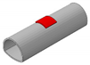 |
| D20 | 20 | |||||||
| D30 | 30 | |||||||
| D40 | 40 | |||||||
| D50 | 50 | |||||||
| D60 | 60 | |||||||
| D70 | 70 | |||||||
| D80 | 80 | |||||||
| V15D | 50 | 3.3 | 3.3 | 10.89 | ||||
| V30D | 6.6 | 6.6 | 43.56 | |||||
| V45D | 8.8 | 8.8 | 77.44 | |||||
| V60D | 3.3 | 3.3 | 10.89 | |||||
| V80D | 6.6 | 6.6 | 43.56 | |||||
| Ⅱ | AP30 | 30 | / | / | 0.5 | Surround tunnel lining |  | |
| AP50 | 50 | |||||||
| AP70 | 70 | |||||||
| AP90 | 90 | |||||||
| Grade | Description of the Influence on the Safety of the Lining | Decrease of the Safety Factor | Identification Criteria |
|---|---|---|---|
| Ⅰ | Little influence | 0~5% | AD < 10; AS < 25 |
| Ⅱ | Certain influence, the inspection frequency should be improved, and daily maintenance should be pay attention. | 5~20% | S < 50%; 100% > D > 80%; AS > 25; 10 < AD < 25 |
| Ⅲ | Big influence, suggest being repaired. | 20~40% | 50% < S < 70%; 70% < D < 80% |
| Ⅳ | Significant influence, should be treated immediately. | 40~60% | D < 70%; AD > 25; S > 70% |
Publisher’s Note: MDPI stays neutral with regard to jurisdictional claims in published maps and institutional affiliations. |
© 2020 by the authors. Licensee MDPI, Basel, Switzerland. This article is an open access article distributed under the terms and conditions of the Creative Commons Attribution (CC BY) license (http://creativecommons.org/licenses/by/4.0/).
Share and Cite
Ye, Z.; Zhang, C. Influence of Loose Contact between Tunnel Lining and Surrounding Rock on the Safety of the Tunnel Structure. Symmetry 2020, 12, 1733. https://doi.org/10.3390/sym12101733
Ye Z, Zhang C. Influence of Loose Contact between Tunnel Lining and Surrounding Rock on the Safety of the Tunnel Structure. Symmetry. 2020; 12(10):1733. https://doi.org/10.3390/sym12101733
Chicago/Turabian StyleYe, Zijian, and Chengping Zhang. 2020. "Influence of Loose Contact between Tunnel Lining and Surrounding Rock on the Safety of the Tunnel Structure" Symmetry 12, no. 10: 1733. https://doi.org/10.3390/sym12101733