1. Introduction
Supercapacitors are promising energy storage technologies with high energy density and high charging/discharging capabilities [
1]. They allow for the storage of electrical energy in electric fields, increasing their efficiency in comparison with mechanical or chemical devices [
2]. Supercapacitor energy storage (SCES) and superconducting magnetic energy storage (SMES) are the only two devices that store energy in the form of electromagnetic fields [
3]. Nevertheless, SCES systems are preferred because they work with voltage source converters [
1], which are common and represent the cheapest option when compared with the current source converters in SMES applications [
4]. Additionally, another advantage of using SCES over SMES systems is that the former does not require special thermal covers, such as those needed for cooling systems based on liquid hydrogen, helium, or nitrogen [
3]. This increases the acquisition, installation, and maintenance of SMES systems.
The integration of SCES systems via voltage source converters allows controlling the active and reactive power independently by formulating a dynamic model in any reference frame (i.e., time domain or
, Clark’s or
, and Park’s or
reference frames, respectively) [
5]. In addition, the dynamical model of the SCES system exhibits a nonlinear structure that makes it necessary to propose nonlinear controllers to deal with its operational goals. Multiple controllers for SCES systems integration in electrical networks have been proposed such as feedback linearization methods [
6], interconnection and damping PBC approaches [
3,
5], linear matrix inequalities [
7], classical proportional-integral controls [
8], adaptive predictive control [
9], or proportional-integral passivity-based control (PI-PBC) methods [
2], that typically control active and reactive power in an indirect form by controlling the currents on the AC side of the converter. Two interesting approaches based on IDA-PBC and PI-PBC approaches have been reported by [
10,
11] to control SMES and SCES systems in autonomous applications of single-phase microgrids; these PBC approaches take the advantages of the port-Hamiltonian modeling to propose asymptotically stable controllers of Lyapunov. Authors confirm that single-phase converters allow the control of active and reactive power independently; nevertheless, the main disadvantage is the dependence on the parameters of the control laws, which complicates their application over systems with parametric uncertainties.
Note that PBC approaches are preferred to operate SCES systems because their dynamic models exhibit a port-Hamiltonian (pH) structure in open-loop, which is a suitable structure that is employed in PBC designs. Because it allows proposing closed-loop control structures that can guarantee stable operation in the sense of Lyapunov [
12]. Even though the PI-PBC method has been previously presented for SCES systems by [
2], who presented a direct power control structure, we proposed a robust parametric approach that avoids prior knowledge on the system parameters (inductance, resistance, and supercapacitor values) and does not require the solution of additional differential equations. This is a gap that is yet to be solved in specialized literature for SCES applications in AC distribution networks. In addition, the main advantage of using direct power control is that the state variables to design the controller are directly active and reactive power. Making more suitable the assignation of the references to control these variables in generation or load compensation applications, while classical approaches work with currents as state variables requiring additional steps regarding active and reactive power control.
The remainder of this paper is organized as follows:
Section 2 presents a complete dynamical formulation of the SCES system interconnected to AC grids with a series resistive-inductive filter. In addition, we present its pH intrinsic formulation and its transformation from the current structure to the power ones.
Section 3 presents the structure of the proposed PI-PBC approach, highlighting its independence regarding the filter parameters and provides a general proof to guarantee asymptotic convergence.
Section 4 reports the general control structure as a function of active and reactive power measures as well as the physical constraints related to the integration of SCES in distribution networks.
Section 5 presents the test system, simulating conditions, and numerical results with their corresponding analysis and discussion.
Section 6 details the main conclusions derived from this research.
2. Dynamical Modeling
To obtain the dynamical representation of the SCES system integrated with VSC, only Kirchhoff’s laws and the first Tellegen’s theorem is required. Here, we suppose that all the variables were transformed from the
reference frame into Park’s reference frame [
5].
where
l and
r are the series inductance and resistance of the AC filter (transformer), respectively;
is the capacitance value of the SCES system;
and
represent the direct- and quadrature-axis currents, respectively, while
and
are their corresponding voltages;
is the voltage in the terminals of the supercapacitor and,
and
are the modulation indexes of the converter that work as control inputs. Note that dynamical Model (
1)–(
3) is a sub-actuate control system because there are
control variables and
states.
Remark 1. The dynamical Model (1)–(3) exhibits a non-affine port-Hamiltonian structure as follows:where is the inertia matrix, which is diagonal and positive definite, and are the interconnection and damping matrices, such that is skew-symmetric and is diagonal and positive semidefinite; and are the state and control vectors; and corresponds to the external input vector. Lemma 1. The dynamical Model (1)–(3) can be transformed into a direct-power control (DPC) model preserving its non-affine port-Hamiltonian structure by defining the following variables as recommended in [2]: , , and , where because the PLL is referred to the direct-axis. Proof. To obtain a DPC model, let us suppose that the
and
signals are obtained by implementing a phase-looked loop (PLL), such that they (i.e.,
and
) are constants and well known. Now, if we derive the active and reactive power components, then,
where, if we substitute Equation (
1) and (
2) considering that
, the following result is obtained
Note that if we multiply Equation (
3) by
and rearrange some terms, then
Finally, when expressions Equations (
5) to (
7) are rearranged in the form of Equation (
4), the proof is completed with
□
Remark 2. Considering the advantages of the pH formulation exhibited by the DPC controller, an appropriate controller to alleviate the active and reactive power oscillations with the SCES systems is the passivity-based control approach because it takes advantage of the pH model to design an asymptotically stable controller in the sense of Lyapunov.
3. Passivity-Based Control Design
PBC control is a powerful nonlinear control technique that allows designing stable controllers by taking advantage of pH modeling. The main objective of the PBC is to find a set of control laws that help to preserve the pH structure of the dynamical model in closed-loop to guarantee stability in the sense of Lyapunov, using energetic modeling [
12]. There are different approaches based on the PBC theory; the most known approach corresponds to the interconnection and damping assignment (IDA-PBC) because it allows working with linear, nonlinear, and non-affine dynamical systems [
13]. Nevertheless, there is also an interesting alternative that includes the well-known advantages of the PI actions in the PBC design, which produces a stable PI-PBC approach that guarantees stability in closed-loop operation; however, this approach is only applicable in nonlinear systems with a bilinear structure such as the case of the dynamical models of the power electronic converters [
2]. In the next subsection, we will present the general PI-PBC design for bilinear systems.
3.1. Bilinear Representation
To develop a controller based on the PI-PBC approach, let us make the following definition.
Definition 1. An admissible equilibrium point () exists for non-linear dynamical Model (4) if its variables are represented in Park’s reference frame (direct- and quadrature-axis), such thatfor some constant control input . Considering the definition of the equilibrium point, now we use some auxiliary variables to develop a PI-PBC controller as follows: and , where and represent the error of the state variables and control inputs.
Note that if we subtract Equation (
8) from (
4), the following result is obtained
To simplify Equation (
9), let us define the property related to bilinear systems as follows:
Definition 2. The matrix product has a bilinear structure if it can be separated as a sum as followswhere and are constant matrices with skew-symmetric structure. Now, if we consider the Definition 2 in Equation (
9) and make some algebraic manipulations, then the below result is obtained:
Remark 3. Expression (11) is the essential structure to design PI-PBC controllers for bilinear systems, as demonstrated in [14]. 3.2. Lyapunov’s Requirements for Stability Analysis
To guarantee that the dynamical System (
11) is stable in the sense of Lyapunov for the equilibrium point
, i.e.,
, let us define a candidate Lyapunov function
with hyperboloid structure as presented below
Observe that
meets the first two conditions of the Lyaponov’s stability theorem, i.e.,
, and
. In addition, if we take the temporal derivative of Equation (
12) and substitute Equation (
11), the following result is obtained:
which implies guarantee in stability, if the second term on the right hand side of Equation (
13) is negative definite or at least negative semidefinite. To simplify this expression, let us use the input–output relation
being
the passive output as follows
where
.
Note that Expression (
14) can help us to design a stable controller if and only if the set of control inputs
is selected such that this expression is always negative semidefinite. These characteristics are presented in the next section using a PI controller.
3.3. PI-PBC Design
To obtain a general control law to guarantee closed-loop stability in the sense of Lyapunov, let us employ the following PI control structure
where
and
are the proportional and integral gain matrices and
z is an auxiliary vector of variables related to the integral action.
To prove stability with the control law defined by Equation (
15), let us modify the candidate Lyapunov function in Equation (
12) as follows
with
and its derivative is
which proves that the control input in Equation (
15) guarantees stability in the sense of Lyapunov for closed-loop operation. Observe that in Equation (
16), we consider that
.
Remark 4. The control input Equation (15) can guarantee asymptotic stability in the sense of Lyapunov as proved in [15] by referring to Barbalat’s lemma [14]. 4. Control Structure and Physical Constraint
This section presents the mathematical structure of the control laws for active and reactive power support with SCES systems, as well as the physical constraint that imposes the interconnection of a supercapacitor for energy storage applications.
4.1. Control Law
The presented PI-PBC approach can deal with parametric uncertainties in the SCES system when it is modeled using a direct power formulation (see Model (
7) and (
8)). For its analysis, let us present the general control inputs obtained from Equation (
15) as follows
where
and
are the proportional gains, and
and
are the integral gains, respectively.
Remark 5. The components and in Equation (18) can be neglected as recommended in [16] because they can be considered as constant values to calculate integral actions. It is important to mention that the control inputs of Equation (
18) can remain robust to parametric uncertainties because they do not depend on any parameter of the system. This implies that small variations in these values (e.g.,
l,
r, and
) will not compromise the dynamical performance of the SCES system.
Note that in Equation (
18), the value of
needs to control the active and reactive power interchange between the SCES system and the grid (the values of
and
are defined by the designer because the main interest in SCES applications corresponds to control active and reactive power independently). Therefore, it is necessary to know
to apply the controller. We start from the energy function of the SCES to compute
, as follows:
and the relation between the active power of SCES and VSC can be approximated to
. Hence,
can be given by
with
.
It is important to mention that the stability proof shown in
Section 3.3 may be compromised by replacing Equation (
20) into (
18), which is only valid when
is constant. Therefore, we adopted the time-scale separation assumption between the outer-loop (
) and the inner PI-PBC described in [
17,
18]. Interestingly, the assumption deals with the possible lost stability by only adjusting the integral gain in Equation (
20).
4.2. Physical Operative Constraint
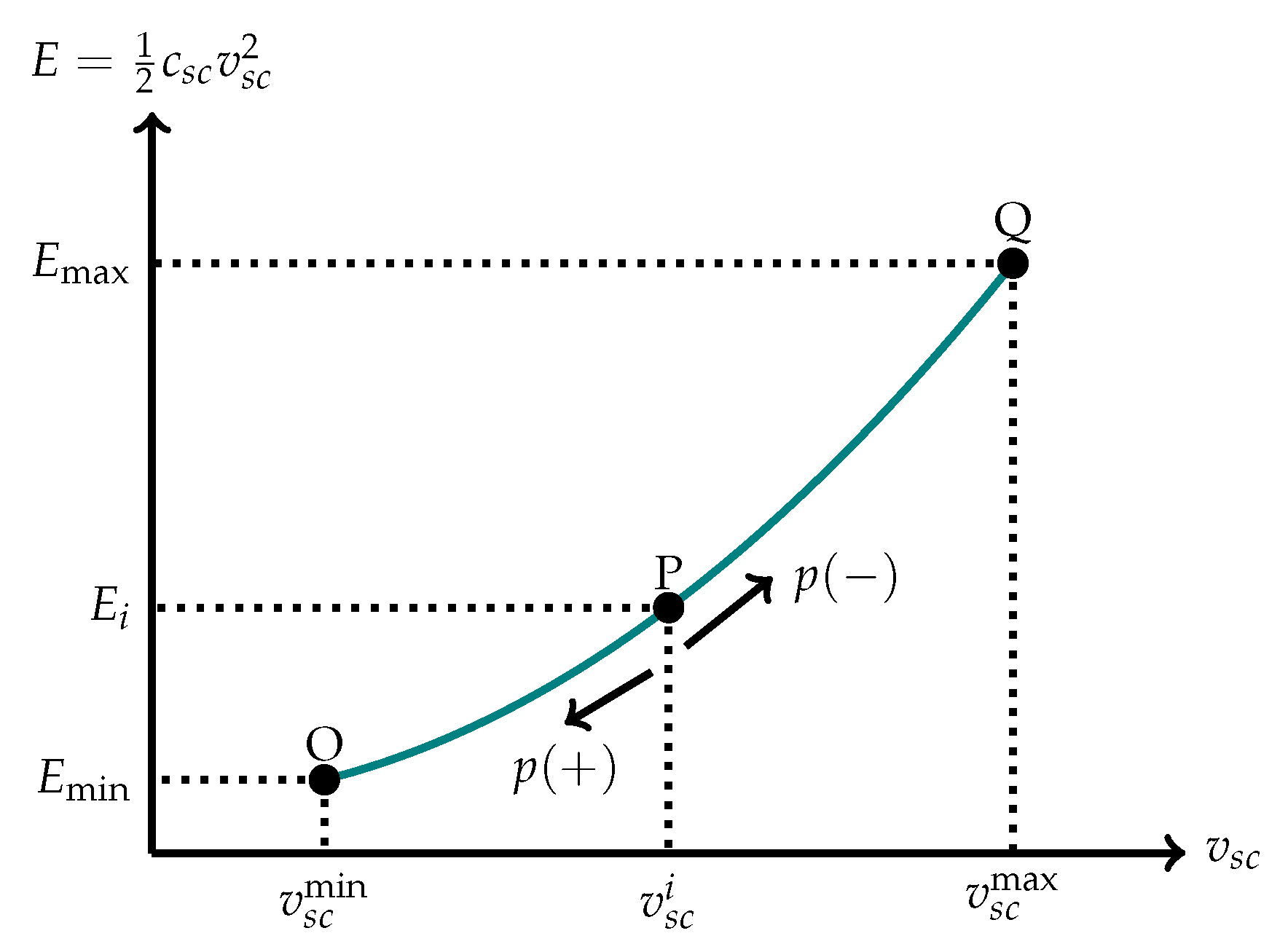
The energy storage capability of a SCES system is limited by the energy capabilities of the supercapacitor as well as for the admissible voltages in its terminals.
Figure 1 presents the dynamic behavior of the total energy stored in the SCES. In this figure, there are three critical points called O, P, and Q. Point O presents the minimum voltage value permissible in the supercapacitor terminals (
) that produce the value of the admissible minimum energy stored (
); this voltage value is the lower bound in the SCES operation to guarantee the controllability of the closed-loop system. Additionally, point Q is the upper bound of the energy storage variable, which reaches the maximum permissible energy stored in the supercapacitor device (
), whereas point P represents some operating points between extreme points of O and Q.
Observe that point P allows positive or negative active power references. In the case in which p is positive, the energy stored decreases from point P to point O. In the case in which p is negative, the energy stored increases from point P to point Q. When point P is at the extreme points, we can conclude that if it is at point O, the reference for p can only be negative or zero, and if it is at point Q, it must be positive or zero. These are necessary conditions to preserve the useful life in the SCES.

 ,
, 


