3.1. Components of the Ontological Model
Under the UPi component, we can understand the list of all types of UP MP. Each MP UP contains information about all the parameters that characterize the MP UP of this type (for example, the number of the route map, the number of the operating card, etc., as well as the type of UP: melting, slab, strip, sheet, roll, etc.).
Under the MP UP attribute, we can understand the data related to the MP UP as a whole. Attributes are usually scalar values, since a single attribute value is defined for a given UP. For example, during cast iron melting these repeatedly appear in the same aggregates. However, in practice, some cases have deviations from the current standards, for example, from melting to melting the gas consumption for purging of the converter may change. As a result, the value of this indicator is unique for each UP [
31,
32].
Moreover, there may be situations in which the attributes have a dimension greater than one. This depends on the particular UP and on the definition of the relevant information request. For example, the average winding temperature of a hot-rolled roll is a scalar for g/k roll, but for a hot-rolled one-and-a-half roll (a roll made up of two rolls rolled independently of each other) the given parameter is a vector containing the temperature values for every roll.
Thus, the data placed in a single HDW MP has a heterogeneous structure that changes over time. In this regard, it is necessary to choose HDW management technologies that provide a dynamic change in the structure of the HDW MP, while maintaining the availability of previously placed data. This method involves the possibility of the dynamic (i.e., during the operation of the system after its launch) addition of sources and parameters, as well as dynamic creation of tables for storing heterogeneous data, for example, PTP with a potentially large number of columns.
Using this approach, a description of the data structure is stored along with the data. This approach has the following advantages. On the one hand, data is collected in tables allowing data blocks to be quickly saved without analysis. On the other hand, the description of the table structure makes it possible to further transform heterogeneous data, for example, analyzing blocks and presenting information for analysis in a “vertical” form. In addition, the structure description can be used when extracting samples, etc. The analysis of data blocks is ensured by identifier columns (for example, the UP number, time, metallurgical length, parameter ID, etc.) which are given in the table, besides columns for parameter storing.
The PCP component of UP MP presents different parameters, namely specified, measured and calculated parameters.
PCP UP at this MP stage is determined at the beginning of the implementation of the corresponding technological process of the MP t-start, further on after its completion at the time t-finish.
Note that there is static information that rarely changes (for example, materials, steel grades, chemical elements, and the relationship between them by the ratio (composition of steel grades)). In this regard, it is advisable to use reference books to store this information.
The observed values of the UP MP parameters are compared with the data in the reference book “Normalization Rules”, which defines the following types of rules: greater than min, less than max, from min to max. Next, according to the reference book “Rationing rule step”, the applicability of this rule is checked.
The list of all possible operands of the rule (identifiers and parameters of the description of the UP MP) is placed in the reference book “Operand of the normalization rule”. As a rule, the parameters of the UP description (the numbers of route and operational maps, the thickness of sheets, etc.) and some collected parameters are used as operands of the normalization rule.
Under the PTP component, we can understand the set of values of the MP technological process indicators which were achieved during the UP production. Frequently, the information on this component is signals-data linked not only to the UP, but also to the time or metallurgical length (for example, the speed of rotation of the lower working roll in the draft stand No. 2). From the informational point of view, signals are vectors of arbitrary dimension. In some situations, a signal is a sequence of argument–value pairs. However, in some cases, the values of the PTP components are scalar values (for example, the metallurgical length in LPC-2), which are linked to the values of the metallurgical length (for example, “temperature and UP at the end of rolling”). The information related to this component of the PTP is a block of data collected at the corresponding stage of the MP with the automated process control system in real time.
Due to the fact that all the data created by the information source must be linked to the source UP ID (for example, at the level of the workshop database, all the data must eventually be linked to the ID in the workshop database), it is necessary to establish a correspondence between the local ID of the information source UP and the ID of the UP of all other sources of information about this MP UP. Next is the process of linking the identifiers of the global and “local” identifiers of the UP.
The following example illustrates the process of linking identifiers. When the event “Processing of a new UP has started” (received from an adjacent unit, the automation of the unit itself, etc.) occurs, the software of the unit requests the external ID of the UP and (or) the number of the UP from the adjacent system. For example, it can be the UP identifier that is the first in the queue for this aggregate. If the external identifier is successfully received, the aggregate software establishes the identifier matching of the IDs. If the external UP identifier could not be obtained, the aggregate software assigns all parameters only to the local ID. Subsequently, on the basis of events data from the UP in the aggregate, and information about queues to the aggregate, an attempt is made to set the correspondence “local ID-external ID” (by the aggregate software itself or the corresponding UPC application). Therefore, to implement the process of linking identifiers, it is necessary to use a “dictionary” which describes:
data sources;
tables that store parameters about UP;
UP parameters;
UP groups;
UP identifiers;
events and transformations with UP;
standardized parameters;
reference books necessary for the operation of the information system.
It is advisable to provide the rights to fill in this “dictionary” to the administrator of the HDW MP, who determines the table structures used for data placement about the UP MP, and, if necessary, modifies them, as well as the administrator responsible for the accuracy of the entered information. Further, the content of the “dictionary” is transmitted to the workshop level using the replication. It is necessary to note that this approach avoids a large number of redundant tables, as it enables the use of unique UP identifiers.
Under the component V, we present the volume of UP production (depending on the production stage, the volume is measured in tons, rolls, or pieces).
Under the component t, we present the fixed time points of the events of the UP MP production process (the beginning and end of the technological process at this stage). This information is the identifier of the data, when it is written to the data in the HDW.
GP PP determines, on the basis of concluded contracts for the supply of GP MP, the range of possible values of their parameters and the terms of their production.
Under the DUP component, we present the relationship between events that occur during UP production, recorded in the incident log (the date and time of the incident, the incident type, the author, i.e., the user who created the incident), which then tracks the entire chain of subsequent actions to eliminate them.
3.2. Description of the HDW MP Entity Model
When constructing an ontology, the heterogeneous data storage model is defined in accordance with GOST R ISO 10 303-11-2009 “The National Standard of the Russian Federation. Automation systems of production and their integration. The presentation of data on this product and the exchange of this data” [
33,
34,
35]. In this paper, we are guided by Part 11 “Methods of description. A reference guide to the “EXPRESS” language of the standard”, which regulates the methodology of products’ description throughout their life cycle. The EXPRESS language is the language designed to describe information within a dynamically changing structure during the product lifecycle, based on specifications. Here, the data scheme is the basis for structuring and interconnecting the elements of the product data representation. The EXPRESS language defines logical objects that can be used to set properties, the scope of acceptable values, and imposes certain restrictions. Graphical notations of EXPRESS T language constructs, called EXPRESS-G. B Edraw [
18], are introduced in the ISO 10303-1 standard. For practical use, the Express-G Diagram software tool has been created.
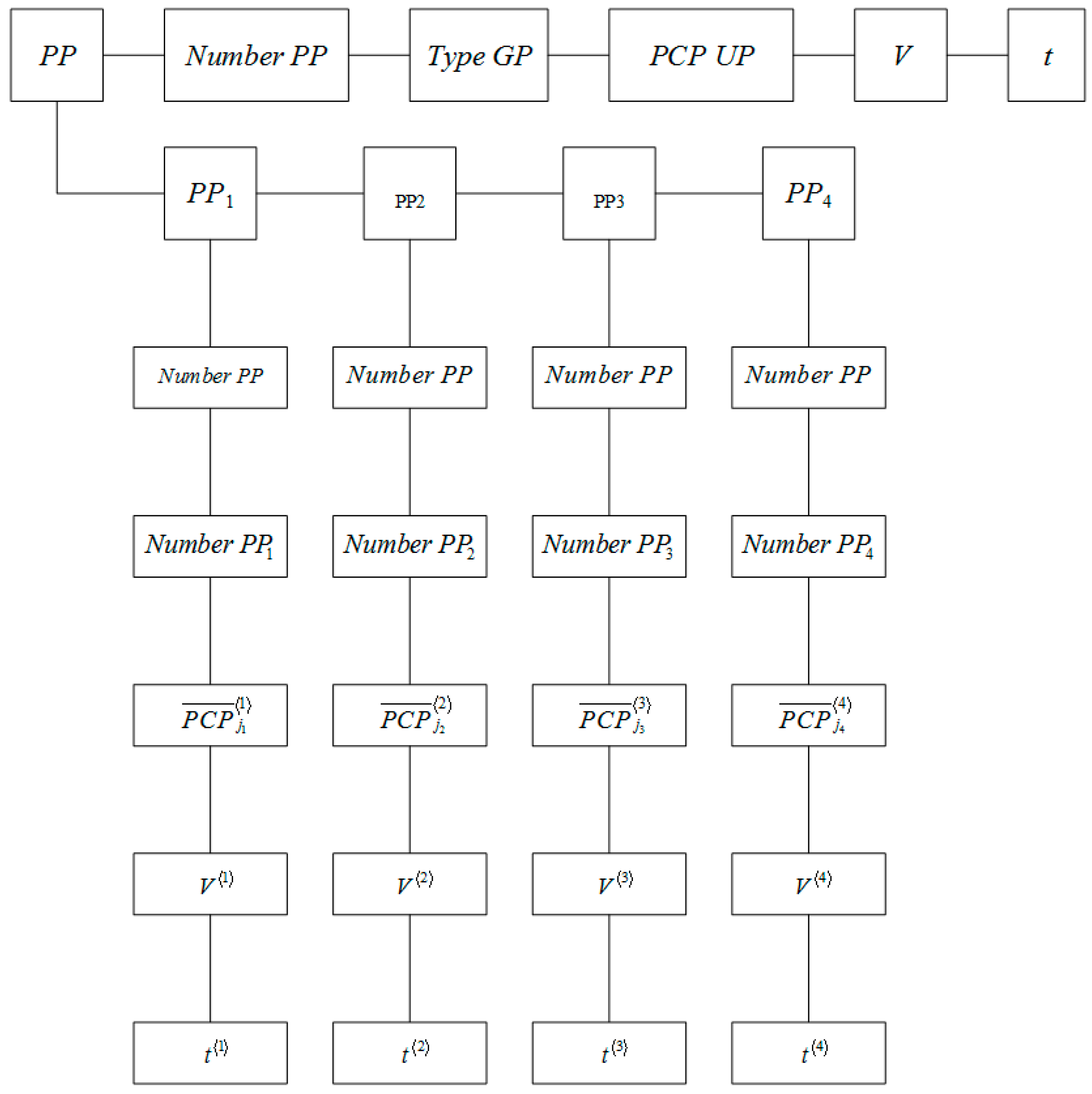
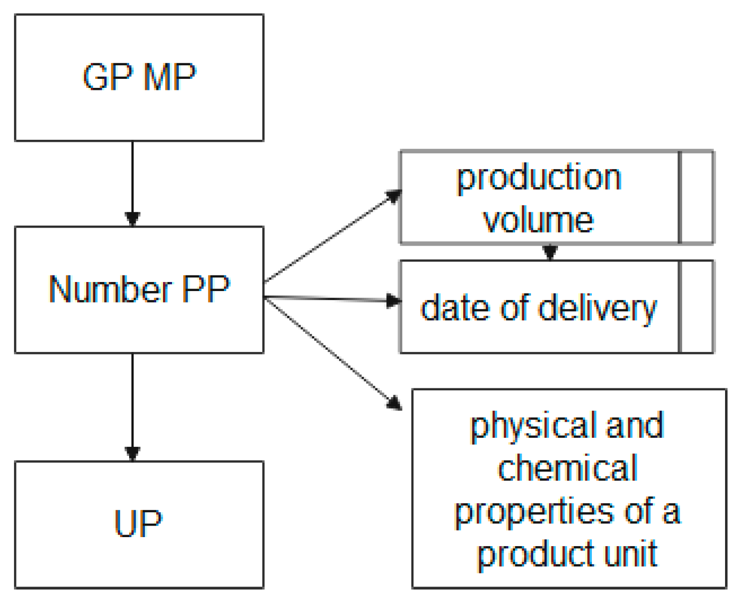
Due to the fact that the basic element is the UP, it is necessary to describe the structural relationship of the UP MP entities. The block diagram of the “GP MP” entity in the EXPRESS-G graphical representation language is shown in
Figure 5.
Figure 5 shows that the “GP MP” entity, which stores the name, nomenclature code, measurement units, etc. at the attribute level, is associated with the “PP Number” and “UP” entities.
The entity “PP Number”, the number of the production plan formed on the basis of concluded contracts for the product range, has attributes containing information about the type and volume of the ordered UP, the terms of their production, and the PCP of the UP. This attribute is a regulatory indicator for monitoring the implementation of contracts.
The “UP” entity is the connecting entity between various block diagrams.
The description of the block diagram of the entity “GP MP”, shown in
Figure 5, in the EXPRESS language has the form:
| SCHEMA GP MP; |
| ENTITY GP MP; |
| END_ENTITY; |
| ENTITY Number PP |
| SUBTYPE OF (GP MP); |
| Output volume; |
| Delivery date; |
| END_ENTITY; |
| ENTITY PCP UP; |
| END_ENTITY; |
| ENTITY UP; |
| SUBTYPE OF (GP MP); |
| END_ENTITY; |
| END_SCHEMA; |
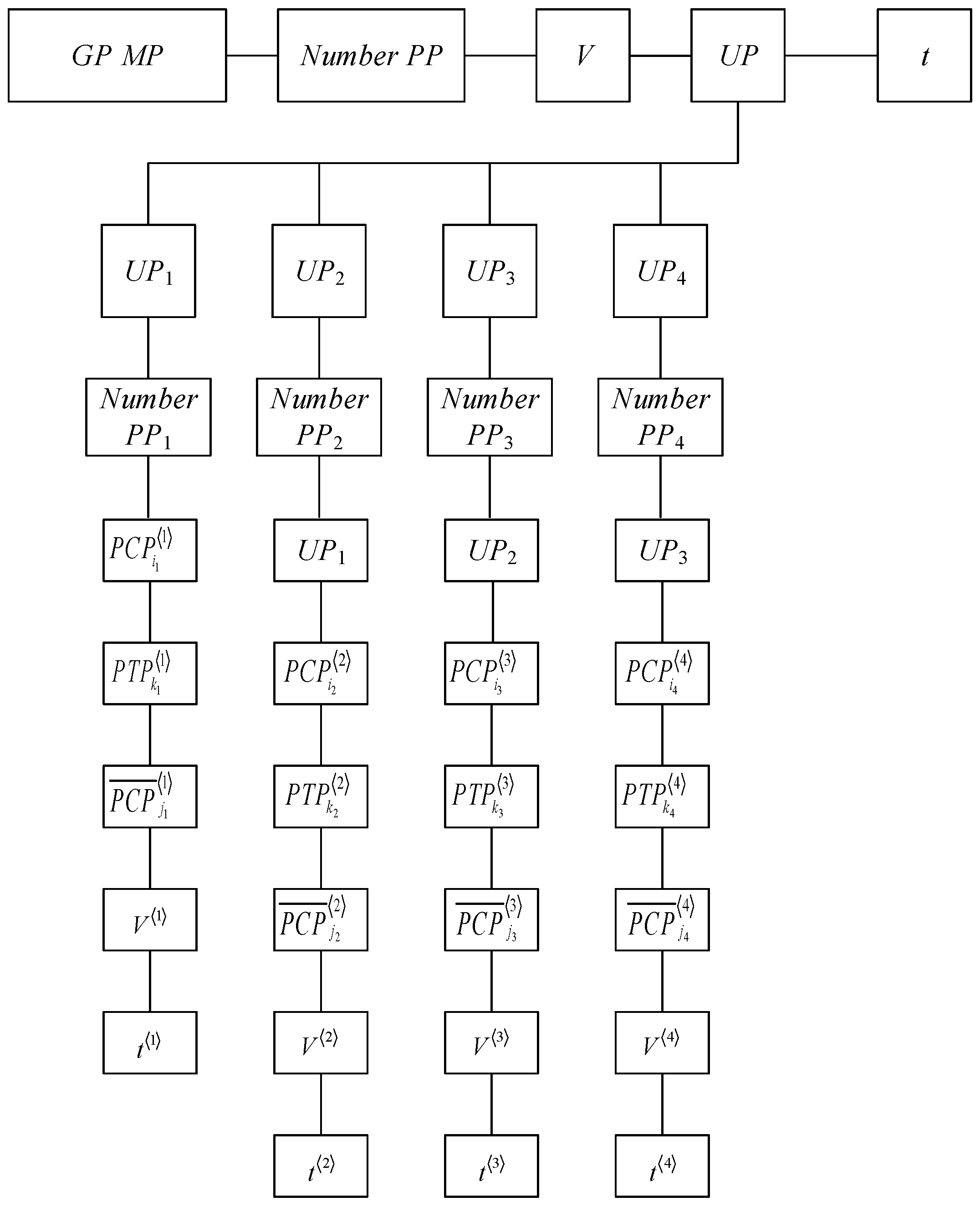
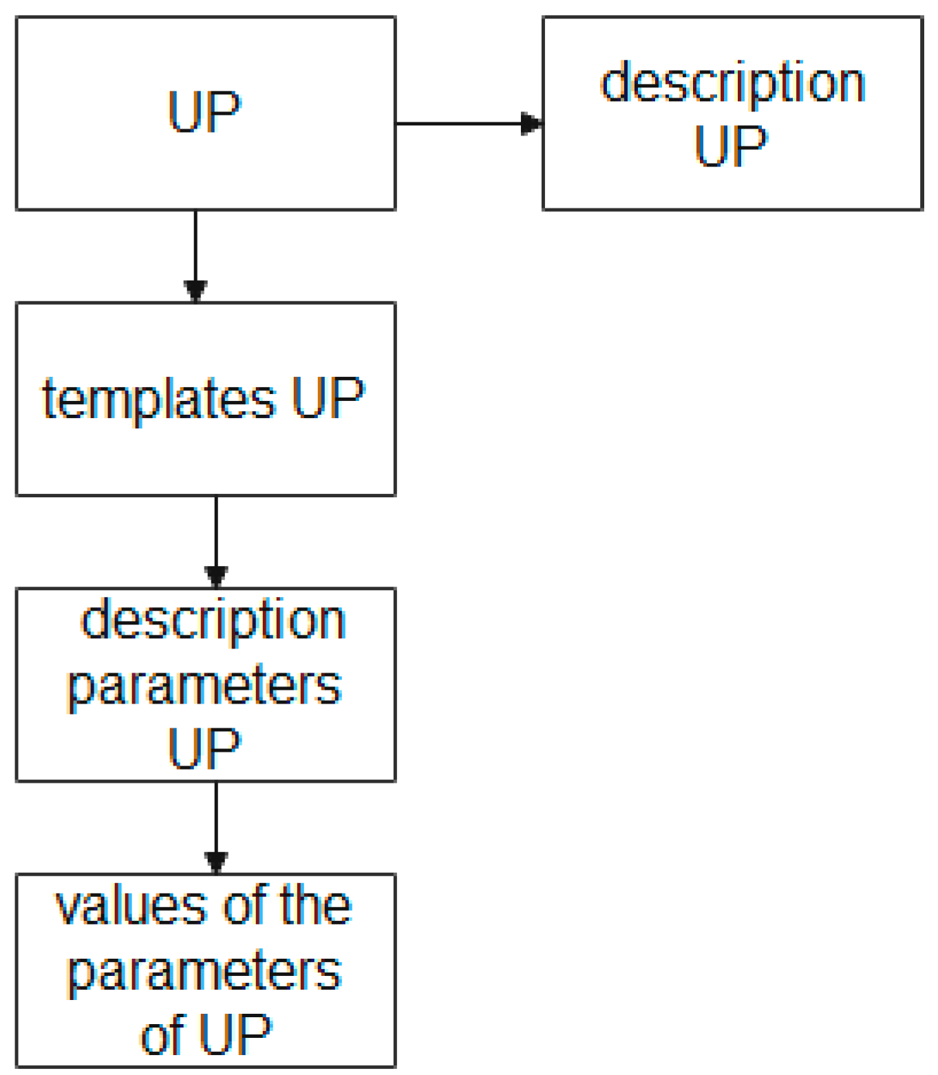
The block diagram of the “UP” entity in the EXPRESS-G graphical representation language is shown in
Figure 6.
Figure 6 shows that the entity “UP”, which stores the description of the UP at the attribute level, is associated with the entities “UP template”, “parameters of the description of the UP”, and “values of the UP parameters”. Here, the entity “UP template” allows the creation and storage of layouts of the UP description for different production stages; the entity “UP description parameters”, at each stage, is to set its own template and store the parameters regulated by the specification of this UP; the entity “UP parameter values” provides storage of the parameter values according to the specification given by the UP.
The description of the block diagram of the “UP” entity, shown in
Figure 6, in the EXPRESS language has the following form:
| SCHEMA description_UP; |
| ENTITY UP; |
| END_ENTITY; |
| ENTITY UP description |
| SUBTYPE OF (UP); |
| END_ENTITY; |
| ENTITY template_UP |
| SUBTYPE OF (UP); |
| END_ENTITY; |
| ENTITY PARAMETER_UP |
| SUBTYPE OF (template_UP); |
| END_ENTITY; |
| ENTITY value_UP |
| SUBTYPE OF (template_UP); |
| END_ENTITY; |
| END_SCHEMA; |
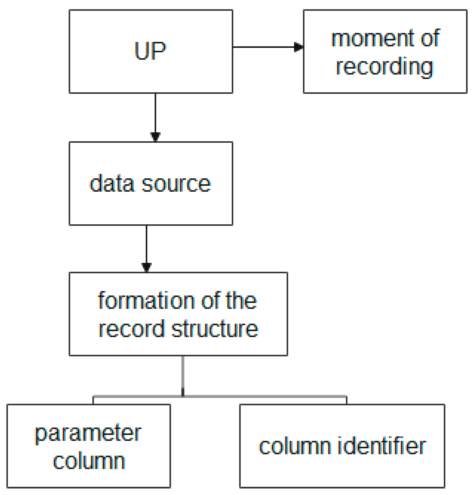
The block diagram of the entities used to form the UP structure in the EXPRESS-G graphical representation language is shown in
Figure 7.
Figure 7 shows that the process of forming the UP structure is described using the following entities: the “UP” entity, the “moment of recording” entity, the “data source” entity, the “formation of the record structure” entity, the “parameter column” entity, and the “identifier column” entity.
The “moment of recording” entity provides storage of the date and time of events that occur during the production process of the GP MP, which allows the linking of the data to the corresponding moment of the life cycle of the UP at various production stages.
The “data source” entity provides the collection of data about the sources of information on each of the divisions of the MP. (Recall, the source of information can be an information system, a node, an aggregate, or information from a user at the workshop level.)
The “formation of the record structure” entity, which attributes depending on the source of information and has different structures and rate of data accumulation, provides the use of tables with a dynamically changing structure of attributes and data types.
The “parameter column” and “column identifier” entities provide storage and access to heterogeneous MP data.
The description of the block diagram of the entity “UP”, shown in
Figure 7, in the EXPRESS language has the following form:
| SCHEMA formation_UP; |
| ENTITY UP; |
| END_ENTITY; |
| ENTITY moment_records_UP; |
| SUBTYPE OF (UP); |
| END_ENTITY; |
| ENTITY Data source_UP |
| SUBTYPE OF (UP); |
| END_ENTITY; |
| ENTITY forming the record_UP structure |
| SUBTYPE OF (UP); |
| END_ENTITY; |
| ENTITY column_parameter |
| SUBTYPE OF (forming the structure of the notation_UP); |
| END_ENTITY; |
| ENTITY column_identifier |
| SUBTYPE OF (forming the structure of the notation_UP); |
| END_ENTITY; |
| END_SCHEMA; |
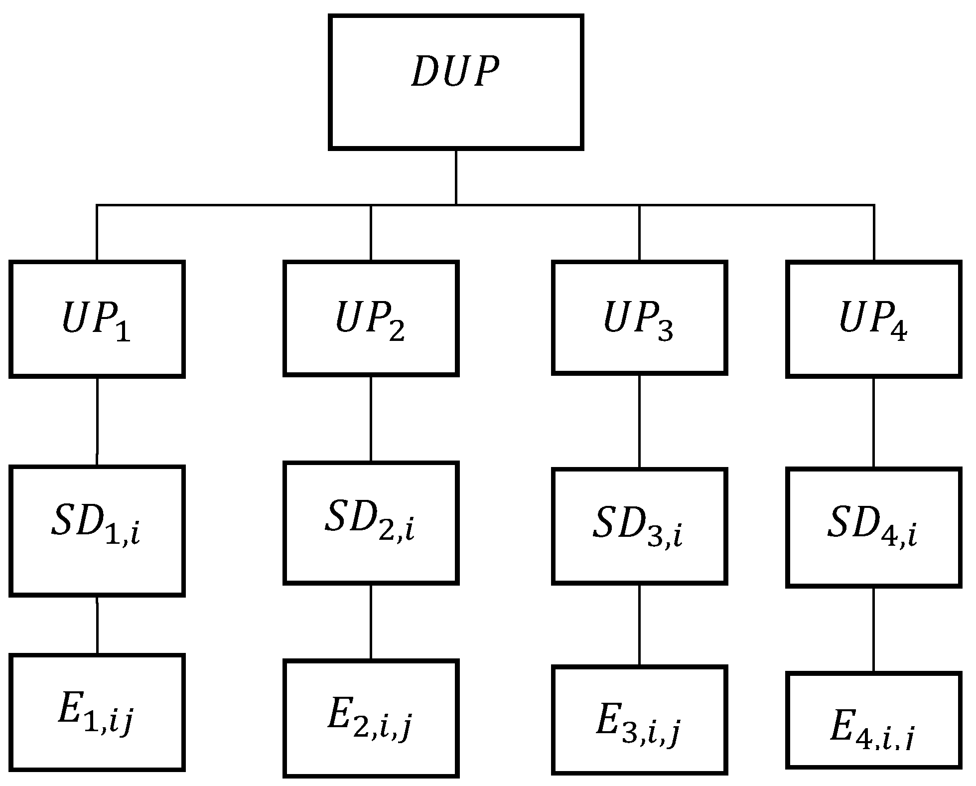
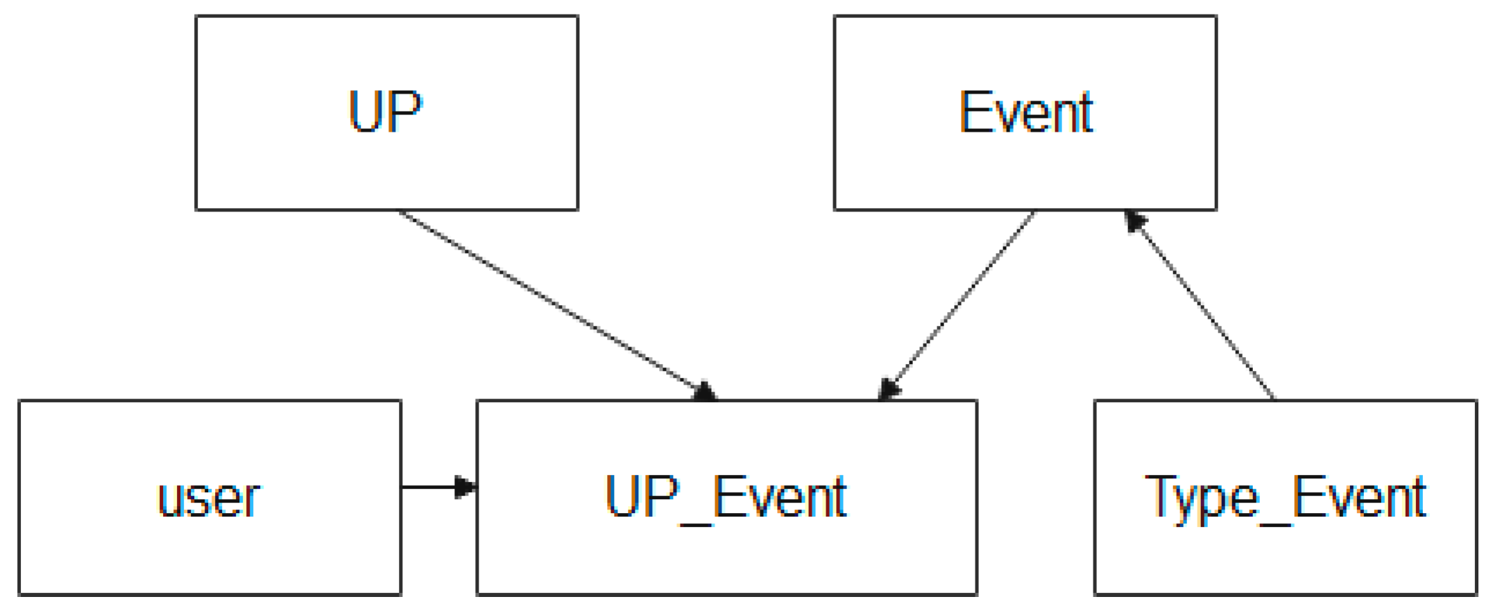
The scheme of entities that are used in the description of the process of storing information about events during the UP MP life cycle in the EXPRESS-G language is shown in
Figure 8.
Figure 8 shows that the entity relationship scheme used to describe the process of storing data about events that occur during the UP lifecycle is described using the following entities: the “event” entity, the “user” entity, and the “event type” entity.
The “event” entity provides the creation and storage of control points of the production process, where recorded information about the UP of the MP is created (for example, the start of production of a batch of products, the end of production of a batch of products, deviation by a parameter of the production process, and other facts).
The “role” entity provides a record of the level where the event is recorded, and who it was recorded by.
The Event Type entity provides event categorization.
The description of the block diagram of entities used to describe the process of storing data about events that occur during the life cycle of the UP, shown in
Figure 8, in the EXPRESS language has the form:
| SCHEMA Event_UP; |
| ENTITY UP; |
| END_ENTITY; |
| ENTITY Event; |
| END_ENTITY; |
| ENTITY Event_UP |
| SUBTYPE OF (UP, Event); |
| END_ENTITY; |
| ENTITY type_Event |
| END_ENTITY; |
| ENTITY user |
| END_ENTITY; |
| END_SCHEMA; |
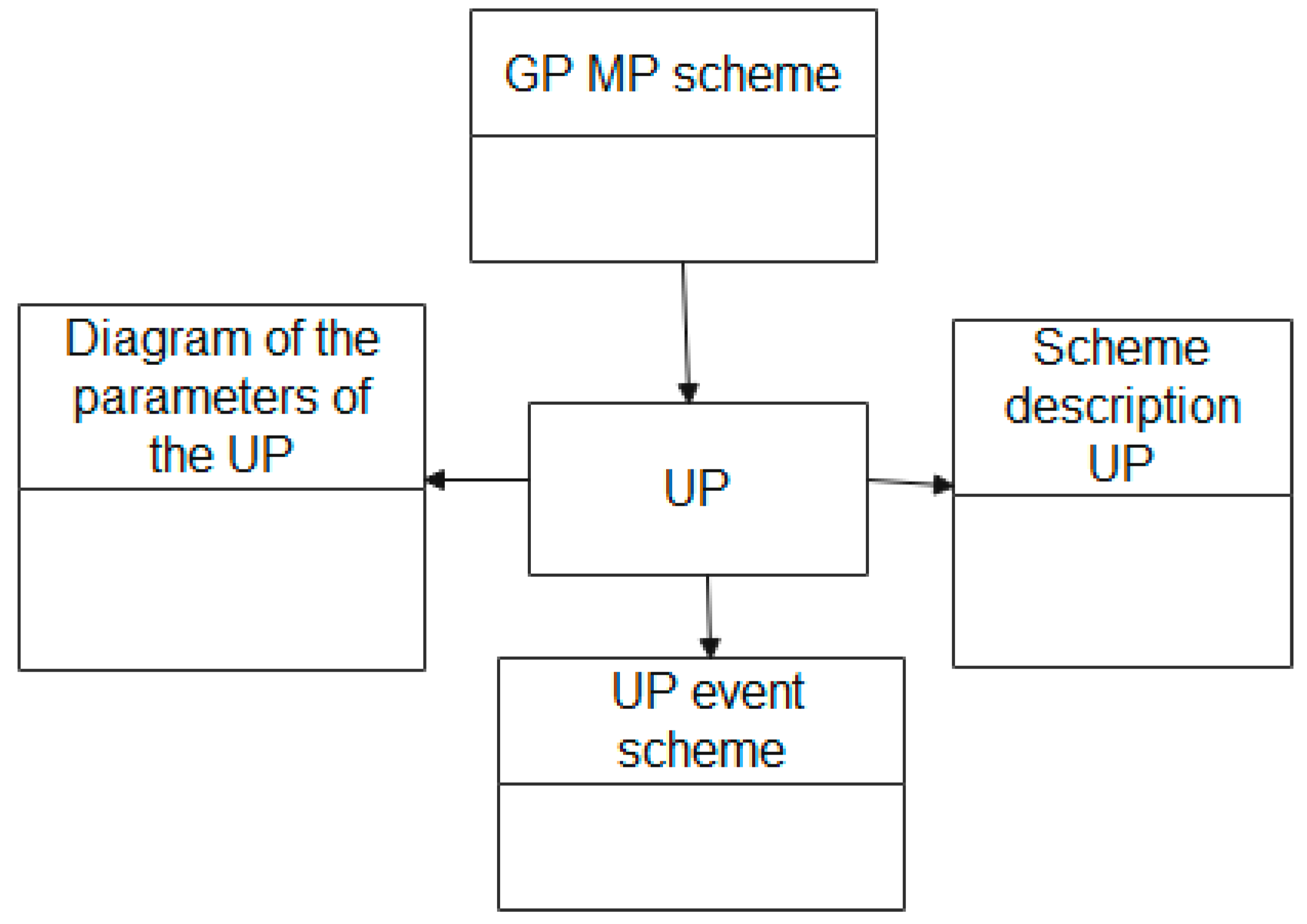
The scheme of entities that are used in the description of the process of storing information about events during the UP MP life cycle in the EXPRESS-G language is shown in
Figure 9.
The description of the entities block diagram which is used to describe the UP attribute scheme, shown in
Figure 9, in the EXPRESS language has the following form:
| SCHEMA connection_scheme_UP; |
| ENTITY UP; |
| END_ENTITY; |
| SCHEMA GP MP; |
| END_SCHEMA; |
| SCHEMA Scheme UP parameters; |
| END_SCHEMA; |
| SCHEMA Scheme UP description; |
| END_SCHEMA; |
| SCHEMA Schemes of UP event; |
| END_SCHEMA; |
| END_SCHEMA; |
The constructed ontological model of GP MP allows making a reasonable conclusion that the entity “GP MP” includes the following classes of entities (
Table 1):
The use of given entities, as will be shown in the next section, provides scientific rationale for a single HDW MP logical structure, which provides storage and access to the following heterogeneous information:
information about data sources;
information about UP parameters and methods to group them;
information about identifiers;
information about UP description;
information about UP events and transformations;
information about UP groups;
information about standardized parameters;
information about the system subjects;
information about the actions with system subjects;
information about the linking of UP identifiers;
background information.
Thus, ontological modeling provides the formation of an entity model of the data collected at various stages of the UP MP life cycle and describes the relationships between the data blocks used for the analysis of production processes, in order to identify the causes of defects and optimize the MP business processes.


