1. Introduction
Recently, autonomous mobile robots have been attracting increasing attention due to their extreme importance for daily human life in many applications that include industrial and medical aspects. The type of mobility categorizes the mobile robot into omnidirectional (holonomic) and nonholonomic. Omnidirectional mobile robots (OMRs) have attracted greater attention as a result of maneuvering proficiency; that is, they can modify the direction of motion without needing to utilize midway steps compared with the conventional nonholonomic mobile robots [
1]. Although the OWMR is not alone in the field of holonomic mobile robots, it outperforms other OMRs such as the legged robots in ordinary terrain due to its energy efficiency and low complexity [
2,
3].
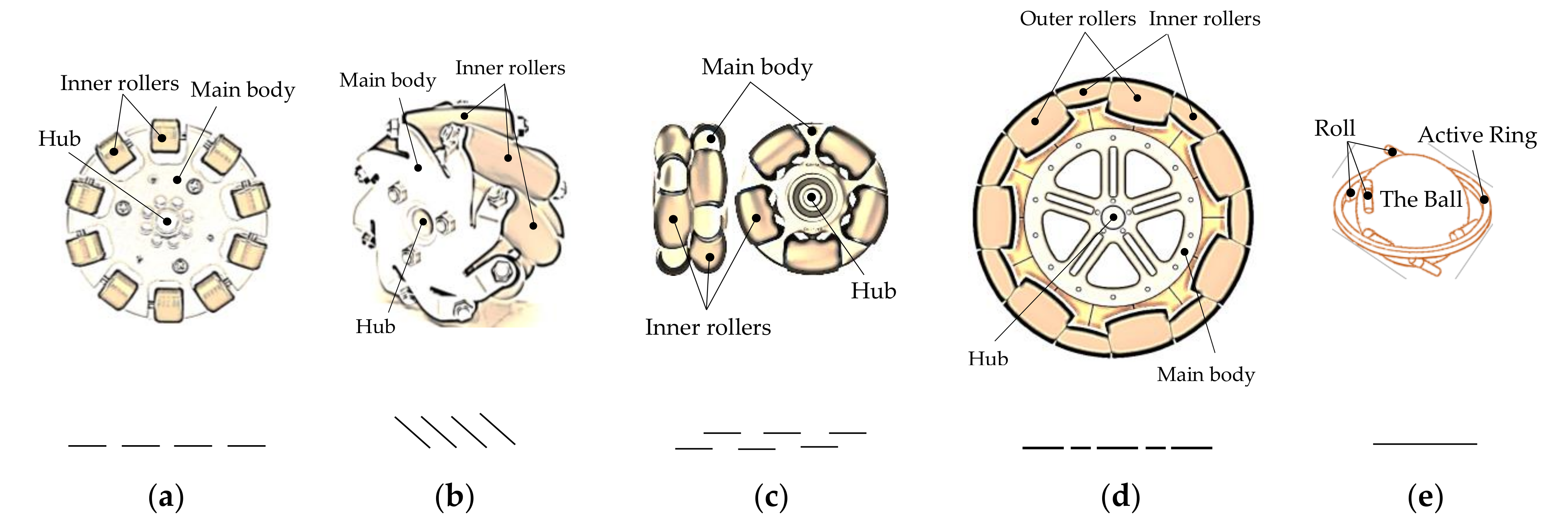
Omnidirectional wheels or what have become known as special wheels are very widespread for OMRs. They were designed to perform active movements in the direction perpendicular to the motor shaft and passive movements in the direction of the motor shaft, providing the mobile robot superior flexibility in an overcrowded environment [
4]. The structures of different types of omnidirectional wheels are depicted in
Figure 1. J. Grabowiecki proposed for the first time the concept of the omnidirectional wheel [
5]. The presented omnidirectional wheel, shown in
Figure 1a, involves a central wheel and multiple inner passive small rollers surrounding the diameter of the wheel that can slide in the direction of the motor shaft. Since the axes of these rollers are perpendicular to the axis of the wheel, this omnidirectional wheel design is known as the orthogonal wheel. The practical use of this version of the omnidirectional wheels led to many issues in terms of the platform movement accuracy and stability such as the vibrations and slippage because of the unbalanced contact concerning the wheel and the ground. Great efforts were made by researchers to create modified designs of the omnidirectional wheels in order to achieve superior improvements. In the work described in [
6], a Swedish engineer constructed a novel design of an omnidirectional wheel, presented in
Figure 1b, called Mecanum wheel, where the passive rollers are mounted on angles in an attempt to achieve continuous contact between the wheel and the ground. The first OWMR with four Mecanum wheels, called URANUS, was assembled in the work described in [
7]. Many studies have been presented on the basis of the Mecanum wheels, such as [
8,
9,
10,
11,
12,
13]. The usage advantages and disadvantages of OWMRs with the Mecanum wheels are discussed in [
14,
15]. The advantages are summarized by the omnidirectional performance that the Mecanum wheel provides, allowing maneuverability and full mobility in an overcrowded environment. Moreover, the Mecanum wheels show better balancing performance compared with the older versions of the omnidirectional wheels. However, the Mecanum wheels have also some weaknesses. A vehicle with Mecanum wheels is subject to slippage. This slippage is challenging to calculate and model. Furthermore, the gap between any two adjacent rollers causes vertical and horizontal vibrations in the moving platform, which evidently affect the accuracy and the stability of the mobile robots. The concept of the dual overlapping parallel omnidirectional wheel, depicted in
Figure 1c, was patented in [
16] as a modified version of the conventional orthogonal wheel aiming to improve the stability and accuracy of OWMRs. This dual omnidirectional wheel has achieved great popularity in both commercial and academic aspects; more than 500 studies have cited and utilized this model. In [
17], another enhanced version of the orthogonal wheel, represented in
Figure 1d, that ensures continuous contact between the surface of the wheel and the ground was proposed to achieve stability improvements by minimizing the gaps between the rollers. An alternative special wheel scheme of the omnidirectional wheel, displayed in
Figure 1e, is the ball wheel mechanism [
18]. It uses two arrays of rollers disposed around two circles and an active ring capable of rotating around an axis through the center of the ball. It has been proven that an OWMR with three such ball wheel mechanisms possesses full mobility.
Another essential matter with regard to determining the number of the special wheels is their distribution on the circumference of the OWMR and the extent of its relationship with mobility performance. With regard to OWMRs with the standard Mecanum wheels, it has been proven that the symmetrical rectangular configuration of four wheels is the optimal configuration [
19]. However, three Mecanum wheels distributed evenly on the circular shape platform in order to balance the load could also be used with full mobility performance, as described in [
20,
21]. Concerning the OWMRs with the orthogonal wheels whose roller axes are tangent to the wheel circumference, the most popular design is the circular array arrangement of three or four wheels. Although OWMRs with three omnidirectional wheels possess complete mobility performance, stability problems could be raised in some cases due to the high center of gravity [
22,
23]. Incrementing the number of omnidirectional wheels can solve the stability problem [
1]. Sometimes the necessity of promoting the carrying and transportation capacity of an OWMR is an important reason to increase the number of omnidirectional wheels [
24].
Numerous studies on modeling and controlling OMRs have been published. In [
25], the authors presented an algorithm for kinematic feedback control of an OMR with four Mecanum wheels. The method proposed in [
26] determines the trajectory of the wheelchair with manual pushrim drive by utilizing differential control based on the kinematic model. The visualization of the wheelchair motion trajectory is done by the use of independent measurements on both left and right drive wheels. The impact of the differential steering of a wheelchair with a pushrim on variations in the position of the body’s center of gravity was investigated in [
27] based on the kinematic modeling where the transverse relocation of the measured body’s center of gravity in relation to a point on the wheelchair trajectory was assumed by measuring the wheelchair trajectory and the body’s center of gravity. Kinematics modeling and mobility analyses were proposed in [
28,
29] regarding OMRs with three orthogonal wheels. In [
30], resolved acceleration control method, PID method, fuzzy model method, and stochastic fuzzy servo method were used to develop a feedback control system for OMRs with three orthogonal wheels. The research conducted in [
31] presented a motion control method based on an inverse linearized kinematic model. A computationally inexpensive near-optimal trajectory generation and control method was proposed in [
32]. The work presented in [
33,
34] formulated the optimal trajectory generation problem as a near-optimal minimum time trajectory such that the solution is based on a relaxed optimal control problem (OCP).
Various studies conducted in the last few years provided a great amount of novelty and contributions regarding OMRs that utilize special wheels. The authors of [
35] proposed a novel kinematics and dynamics modeling of an OMR with four Mecanum wheels by utilizing the principle of virtual work where the control of the actuators is done by the presented dynamic model equations. A novel energy modeling method for mobile robots is proposed in [
36], allowing the robots to calculate and predict energy consumption. In the work presented in [
37], the inverse and forward kinematics for an OMR with six Mecanum wheels are detailed and simulated. The control method of an OWMR with four omnidirectional wheels proposed in [
38] depends on the use of a 32-bit ARM microcontroller so that the kinematic modeling will be utilized as feedback. In the work presented in [
39], a model predictive fault-tolerant control (MPFTC) scheme was designed for an OWMR with four Mecanum wheels in order to appropriately exploit the inherited actuation redundancy of the robot. In the work presented in [
40], a type-2 fuzzy logic controller was designed for an OWMR in order to control the motor speed of the wheels so that the robot behavior remains maintained. The work presented in [
41] solved the trajectory tracking problem on uneven terrain for an OWMR using a double closed-loop control strategy. In [
42], proportional derivative control tuning was established for OMRs so that the tracking error and energy consumption could be minimized by the use of the dynamic optimization approach. The authors of [
43,
44,
45,
46] designed fuzzy controllers to allow OWMRs to track the desired trajectory. A model predictive control (MPC) algorithm was designed by the authors of [
47] in an effort to achieve point stabilization and trajectory generation. The research presented in [
48] combined the sliding mode control (SMC) with the backstepping technique in order to control an OWMR with four wheels where the kinematic and dynamic model of the robot was utilized in designing the controller. The coupled sliding mode control (CSMC) method was used in [
49] in order to achieve a satisfactory tracking control for an OMR. In [
50], the adaptive robust control was proposed for the trajectory tracking of an OMR in the presence of uncertainties. The study presented in [
51] used a flatness-based control scheme hardware-in-the-loop simulation platform for an OMR where the control input from the simulation model was reassigned to the robot hardware and the feedback to the simulation model was done by a Kinect-based vision system. The trajectory tracking for an OMR with four omnidirectional wheels presented in [
52] was carried out using PID and linear quadratic tracking (LQT)-based controller. In [
53], the author utilized a constrained dynamic inversion-based (CDIB) approach that incorporates vehicle dynamics to solve the optimal trajectory generation problem of an OWMR with three orthogonal wheels. A novel control system was proposed in [
54] based on mixed reality for the path planning of OWMRs. The research presented in [
55] addressed the velocity tracking problem for an OWMR with four Mecanum wheels by utilizing novel voltage-based control law with visual feedback. In [
56], the authors proposed using improved ant colony optimization (IACO) to search for the optimal path for an OWMR.
The obstacle avoidance problem has been seriously considered in many studies discussing the trajectory generation of OWMRs. The algorithm proposed in [
57] plans a reference path that meets the conditions of obstacle avoidance based on Bézier curves, then the motion planning that satisfies the dynamic constraint is solved as a minimum-time optimal trajectory problem. The problem of optimal trajectory in the presence of static obstacles was formulated in [
58] as a constrained nonlinear optimal control problem. However, a direct method of numerical solution was used to solve the problem. Robert et al. in [
59] established a hybrid method of obstacle-avoidance motion planning in dynamic environments where a global deliberate approach is applied to determine the motion in the desired path line and a local reactive approach is used for moving obstacle avoidance. In [
60], the authors proposed a navigation system for an OWMR with three orthogonal wheels to ensure obstacle avoidance by using an MPC strategy through the path obtained by the potential field method. In [
61], vision-based navigation for an industrial OWMR with four Mecanum wheels was proposed, allowing the robot to navigate autonomously and perform anticollision path planning. The research presented in [
62] proposed a hybridized approach based on the use of A* algorithm and the fuzzy analytic hierarchy process (FAHP) together with bio-inspired control method in order to achieve optimal path planning and fast control performance in both static and dynamic working environments. In [
63], the velocity obstacles (VO) approach was integrated with the nonlinear model predictive control (NMPC) in order to accomplish collision avoidance online in the dynamic environment. The research presented in [
64] combined the adaptive controller with type-2 fuzzy logic to achieve trajectory tracking and obstacle avoidance for OMRs. In [
65], a fuzzy behavior-based approach for an OMR with three omnidirectional wheels was proposed to track a target while avoiding obstacles along its path. The work presented in [
66] proposed using swarm intelligence optimization in order to design appropriate path planning methods in static and dynamic environments.
Navigational characteristics and localization analysis are indispensable aspects of mobile robots research, and many recent studies have contributed to this domain. The research presented in [
67] proposed several contributions to the field of indoor localization for ambient assisted living in smart homes, including new methodologies that used multimodal components to detect a user’s indoor location and its spatial coordinates while interpreting the accelerometer and gyroscope data. In [
68], human-aware robot navigation was proposed regarding mobile robots in domestic areas, allowing the mobile robot able to navigate according to the user preferences. The research presented in [
69] developed a method of vision-based indoor mobile robot navigation in which the visual navigation problem is transferred to scene classification. Furthermore, a shallow convolutional neural network was designed for this purpose; it had high scene classification accuracy and efficiency in processing images captured by a monocular camera. In [
70], a multimodal deep learning method was utilized for mobile robot navigation in a static indoor environment. Additionally, a fuzzy-based system was designed in the study to collect the datasets for training the designed multimodal network. In the work presented in [
71], probabilistic approaches for multiple mobile robots in indoor and outdoor environments were designed based on sensor fusion, where the extended Kalman filter (EKF) was used to estimate the position and orientation of the robot. In the work presented in [
72], an autonomous mobile robot was utilized in the agriculture industry; the robot was able to navigate through occluded crop rows and perform various phenotyping tasks, such as measuring plant volume and canopy height using 2D LiDAR. A new localization method proposed in [
73] aimed to address the navigation problem regarding the mobile robot in non-line-of-sight (NLOS) situation. Stereo images obtained by a stereo camera were utilized in [
74] to enhance the localization of a mobile robot. In [
75], a neural network data fusion approach was presented to enhance the real-time performance and the accuracy of localization for mobile robots in indoor environments by eliminating the effects produced by measurement errors. In the research presented in [
76], a light-emitting diode (LED)-based system was designed in order to achieve communication and localization for a mobile robot, and the Kalman filter was used in this system to acquire the prediction of the robot’s position and orientation.
This study aims to derive a compact and complete mathematical model for a symmetrical annular-shaped omnidirectional wheeled mobile robot (SAOWMR) with omnidirectional wheels. This model will provide an opportunity to conduct research, experiments, and comparisons on the base of SAOWMRs with two, three, four, or even more omnidirectional wheels without the necessity to switch models or derive a new model. Moreover, this research also focuses on developing a new computationally effective method based on the complete model of a SAOWMR with n omnidirectional wheels so that improvements in the trajectory planning optimization (TPO) can be achieved. Another aim of this work is to incorporate path constraints so that the SAOWMR can navigate with a collision-free optimal trajectory.
The rest of this paper is structured as follows: The kinematic and dynamic model of a SAOWMR with multiple wheels is presented in
Section 2. In
Section 3, a new computationally effective method is developed in order to achieve improvements in solving the optimal control problem regarding a SAOWMR with
n omnidirectional wheels. In
Section 4, the results obtained by the proposed method are discussed and compared with those produced by the CDIB method to demonstrate the effectiveness of the presented method. The obstacle avoidance navigation process is discussed in
Section 5, and the conclusion of this study is presented in
Section 6.
2. Mathematical Modeling of a SAOWMR with n-Omnidirectional Wheels
2.1. SAOWMR Description and Topology
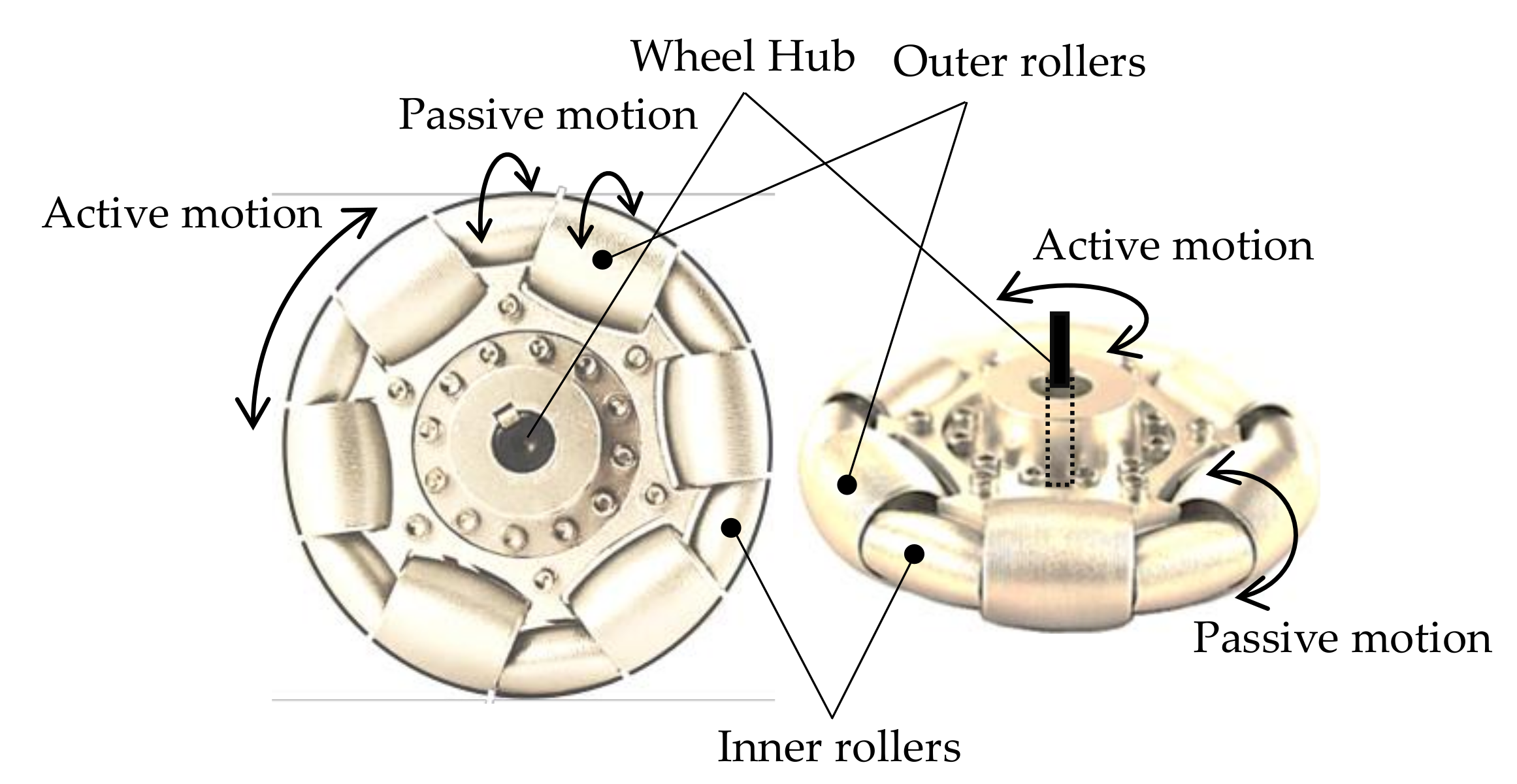
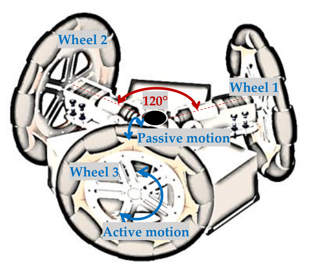
A SAOWMR with more than two omnidirectional wheels is an omnidirectional mobile robot that possesses full omnidirectional motion proficiencies as it can move instantaneously in any direction from any configuration. The maneuverability advantage of this robot is based on the usage of the orthogonal omnidirectional wheels that achieve active movements in the direction orthogonal to the motor shaft and passive movements in the direction of the motor shaft, enabling the wheel to move simultaneously in two directions. Although several types and shapes of the orthogonal omnidirectional wheels are available to be implemented, the continuous alternate orthogonal omnidirectional wheels were selected for use in this study to achieve stable performance as they provide continuous trace between the surface of the wheel and the ground. The considered orthogonal wheel consists of a central wheel carrying a number of inner rollers and larger outer rollers arranged alternately surrounding the circumference of the wheel that can slide freely in the direction of the motor shaft. The angle between the roller axis and the central wheel axis is 90°.
Figure 2 demonstrates the structure and the configurations of the considered continuous alternate orthogonal omnidirectional wheel.
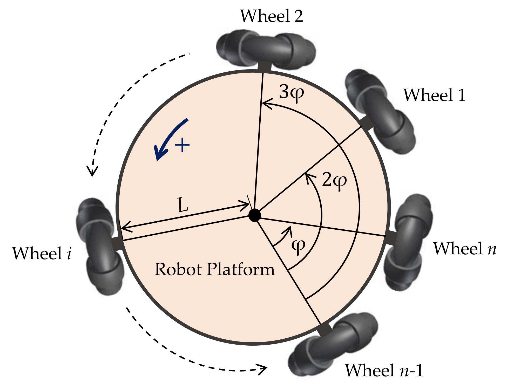
A SAOWMR includes several omnidirectional wheels distributed regularly around an annular-shaped platform. The holonomicity of motion allowing the robot to rotate and translate independently and simultaneously is determined based on the use of three omnidirectional wheels attached to three independent actuators so that motion with 3 degrees of freedom is achievable. Incrementing the number of omnidirectional wheels can solve some stability problems, as shown in [
1]. Moreover, the necessity of promoting the carrying and transportation capacity of the robot is also an important reason to increment the number of omnidirectional wheels [
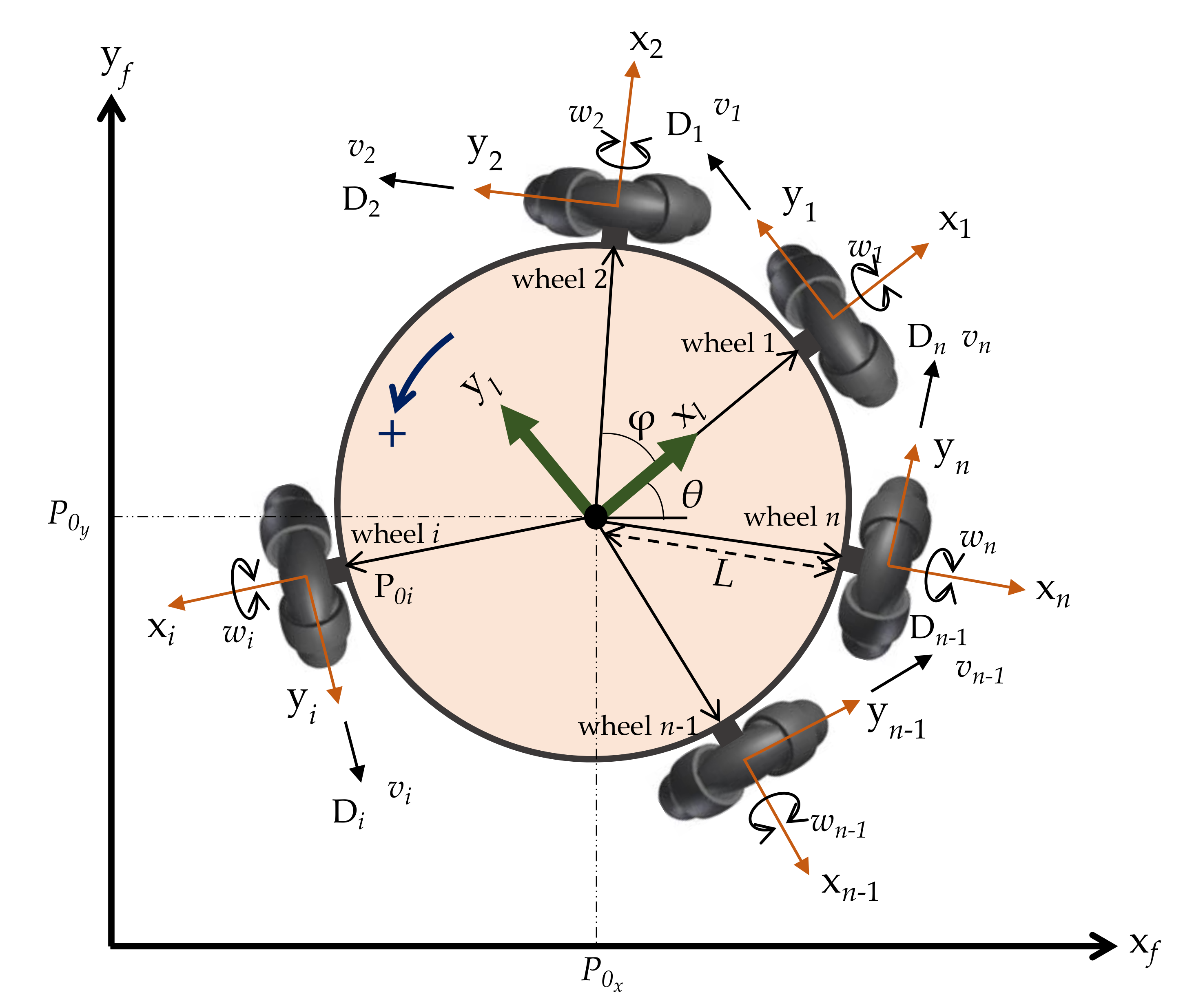
24]. A SAOWMR with only two omnidirectional wheels is still able to move from one configuration to another by breaking up the complex motion into pure rotation and pure translation. The configuration of a SAOWMR with
n- omnidirectional wheels distributed around the robot platform where the angle between any two adjacent wheels is
φ is depicted in
Figure 3. The positive direction of rotation is considered as the rotation in the counter-clockwise direction. Moreover,
L is the radius of the SAOWMR.
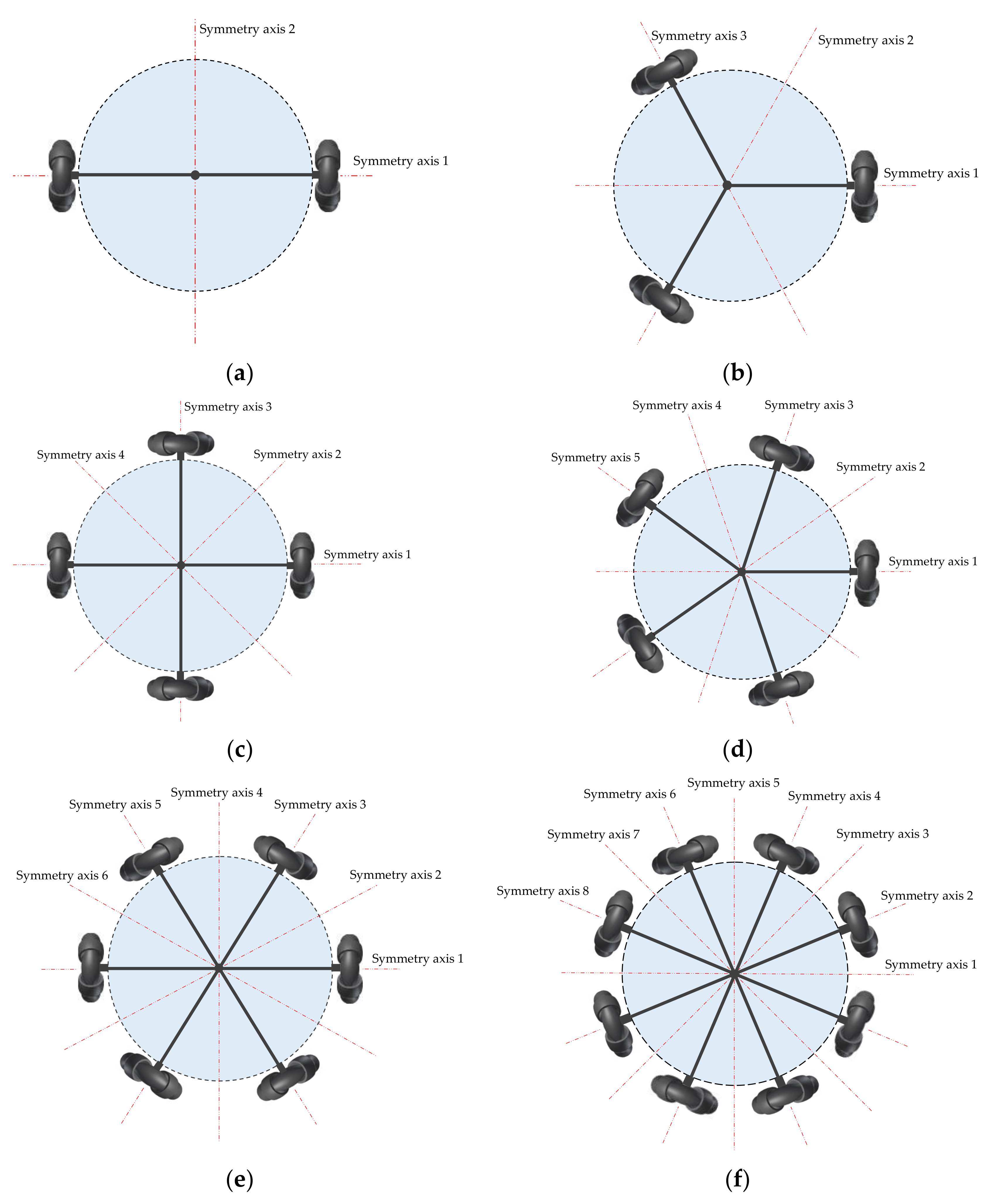
A SAOWMR possesses clear and interesting symmetrical configurations and topology as its geometric shape can be divided into several identical portions that are organized in a systematized manner. Several types of symmetry can be observed clearly in the case of a SAOWMR, including reflexive, rotational, translational, and scale symmetry. Another interesting symmetrical property that can be detected easily in
Figure 4 is that the number of the symmetrical axes of the SAOWMR is equal to the number of its omnidirectional wheels.
Figure 5 shows the real prototype of a SAOWMR with three omnidirectional wheels.
2.2. Geometry of the SAOWMR
The generic configuration of the SAOWMR considered in this study is shown in
Figure 6. The structure of the robot includes
n omnidirectional orthogonal wheels correspondingly prearranged at
degrees on the boundary of the robot platform. In this consideration, the angle
depends on the number of the omnidirectional wheels provided, for example,
equals 180° if the SAOWMR has two wheels and 90° if the robot possesses four wheels. The omnidirectional wheel and its motor shaft hold the same rotational axle. In this sense, translational velocities
are applied to the
n wheels along the directions
, respectively. The angular velocity of the
ith wheel shaft is noted as
. Hence, the positive direction of rotation is defined to be the rotation in the counter-clockwise direction. A local reference frame
is associated with the center of mass of the robot so that the
axis is coincident with the axis of rotation of the first wheel. Another system of
n local reference frames is distributed equally to
n omnidirectional wheels so that the
axis of the frame
corresponds with the rotational shaft of the
ith wheel. Moreover, a system of global reference frame
is defined in order to detect the motion of the robot in such a way that the axes
and
are associated by the angle
θ. The radius of the SAOWMR is noted as
L. The positional vector of the
ith omnidirectional wheel drive is noted as
. The point
is the projection of the center of mass of the robot on the global reference frame.
2.3. Kinematic Model of the SAOWMR
The general transformation matrix between the frame attached to the ith wheel and the local reference frame attached to the center of mass of the robot can be given as follows:
The positional vector of the ith omnidirectional wheel drive unit is calculated in terms of the local reference frame as
The unit vector that states the direction of the ith motor relative to the local reference frame is given by
In Equation (3), R is the rotational part of the transformation matrix T. The general transformation matrix between the local reference frame and the global reference frame can be ensured by
The point is the projection of the center of mass of the robot on the global reference frame. Moreover, we can find the unit vector relative to the global reference frame as given in Equation (5):
The positional vector of the ith omnidirectional wheel drive unit is calculated in terms of the global reference frame as in the following equation:
In order to calculate the velocity of the ith omnidirectional wheel drive, we can take the derivative of Equation (6) as follows:
Equation (7) can be rewritten in matrix form as
The expanded form of the system given in Equation (8) regarding a SAOWMR with n wheels is given as follows:
The matrix expressed in Equation (9) represents the relation between the velocity components of the robot’s wheels and the velocities of the center of mass of the robot in terms of the global reference frame. However, the inverse of the matrix given in Equation (10) is known as the Jacobian matrix
The following useful relation between the drive units’ velocity components and the velocity components of the center of mass of the robot is derived based on the Jacobian Matrix J:
In order to find the individual velocities applied to the robot’s wheels, we need to find the projection of the velocity given in Equation (7) along the unit vector that specifies the drive direction as follows:
Equation (12) is expanded and written in matrix form regarding a SAOWMR with n wheels as shown in Equation (13):
The matrix expressed in Equation (13) represents the inverse Jacobian matrix that relates the individual translational velocities of the robot wheels and the velocity components of the center of mass of the robot. The following kinematic model system in Equation (14) is derived by finding the Jacobian matrix and considering the scalar relation between the angular velocity of the wheel shaft and the translational velocity :
In Equation (14),
is the radius of the omnidirectional wheel. The kinematic model presented in this section can be verified regarding a SAOWMR with three omnidirectional wheels by comparing the model with that stated in [
32].
2.4. Dynamic Study of the SAOWMR
The force generated by the
ith DC motor attached to the
ith wheel with no-slip condition is represented in Equation (15) as follows:
In Equation (15),
is the voltage applied to the input terminal of the
ith wheel DC motor.
is the translational velocity of the
ith omnidirectional wheel. The constants
and
can be determined from the motor parameters and the geometry of the wheels as shown in Equations (16) and (17):
R is defined as the armature resistance of the DC motor, and
is the torque constant of the DC motor. By utilizing Newton’s laws of motion, the linear and angular momentum balance equations can be written as follows:
The mass and the moment of inertia of the robot are
m and
J, respectively. The system in Equation (18) can be rewritten by utilizing the relations in Equations (5) and (15) as follows:
with
The substitution of Equation (13) into Equation (19) yields
By the substitution of the matrix Q into Equation (21), the equations of motion of the SAOWMR are represented as follows:
Equation (22) can be written in compact form by introducing the state vector and the control input vector as follows:
The matrices M and A in Equation (23) are expressed as


