Article

Study of a High-Power Medium Frequency Transformer Using Amorphous Magnetic Material

School of Electrical Engineering, Shenyang University of Technology, Shenyang 110027, China
*
Author to whom correspondence should be addressed.
Symmetry 2022, 14(10), 2129; https://doi.org/10.3390/sym14102129
Submission received: 10 August 2022 / Revised: 25 August 2022 / Accepted: 16 September 2022 / Published: 13 October 2022
(This article belongs to the Section Engineering and Materials)

Abstract

:
A shell-type medium frequency transformer (MFT) using amorphous alloy material is designed for high-power electronic applications. The optimal area product design method is adopted to design an MFT, which maximizes the high efficiency and power density, minimizes the loss and volume, and meets the limitations of insulation and temperature rise. Then, a 20 kVA/10 kHz MFT is designed. To ensure the rationality of the MFT design, the magnetic properties of the amorphous alloy material are measured, and finite element simulations are carried out based on measured magnetic properties. The magnetic flux density, loss, and temperature rise of the designed MFT are analyzed. Finally, a 20 kVA/10 kHz MFT prototype is fabricated, and experimental tests are carried out. The loss and temperature rise of the MFT prototype are within reason, which verifies the effectiveness of the proposed scheme.

1. Introduction

With the rapid development of the DC microgrid and DC distribution power system, a high voltage and high power isolated bidirectional DC/DC converter has received great attention from researchers due to its advantages of bidirectional power flow, high power density, high efficiency, etc. [1,2,3]. In addition, the isolated bidirectional DC/DC converter is the key equipment for realizing large-scale DC source interconnection, DC voltage conversion, and galvanic insulation [4,5]. The structure of the isolated DC/DC converter is shown in Figure 1.
Meanwhile, the MFT plays an important role as an integral part of the isolated bidirectional DC-DC converter. Based on magnetic coupling, the MFT can realize the galvanic insulation and voltage conversion between the high and low voltage sides. In addition, reducing the size and weight of electrical equipment and improving energy efficiency have also been major research goals in recent decades in the field of power transmission [6]. Compared with traditional power transformers, MFTs can greatly reduce their size and weight by increasing the operating frequency and using novel magnetic materials [7]. At the same time, the solid-state transformer (SST) composed of MFT and power converter can easily realize functions such as power flow control and reactive power compensation, as well as improve the intelligence level of the power system [8,9]. Furthermore, various types of MFTs have been developed for emerging applications, such as railway traction, offshore wind power, energy storage system, etc. [10].
Even though the MFTs have many advantages, there are still some major problems compared to traditional power transformers. Since most of the power losses of MFTs are converted into heat, the heat dissipation effect of MFTs is closely related to their structure. Therefore, if the structural design of the MFT is unreasonable, the heat cannot be dissipated in time, which directly affects the life, efficiency, and reliability of the MFT [11]. In addition, high-frequency magnetic materials are more expensive than traditional silicon steel, so the manufacturing cost of MFTs needs to be considered. In order to achieve compact, efficient, and cost-effective, it is necessary to optimize the design of MFTs. Thus, the determination of the core and windings becomes very important.
Some research has been done to develop MFT design methods due to the complexity of the design [12]. Most of the design methods need to occupy a lot of computing resources of the computer to cover the overall design of the transformer and select the optimal design scheme according to the MFT specifications. In order to choose the optimal design scheme based on the results obtained, the designers must have some confidence in the design tool and the models used in the method. Therefore, the mathematical model used in the design process should be as accurate as possible, considering the electrical, magnetic, and thermal aspects of the MFT [13]. Researchers have considered using advanced optimization algorithms to design the MFTs, such as genetic algorithms [14], evolutionary algorithms [15], and antlion optimizer (ALO) [16]. The most used intelligent optimization algorithm is the multi-objective genetic algorithm [17], however, it also requires a lot of computing resources.
In addition, the selection of core material is critical for the design of the MFT, and several magnetic materials have been the most widely used in MFT such as silicon steel, amorphous alloy, nanocrystalline alloy, and ferrite [7].
Silicon steel is widely used in traditional power transformers, but its loss increases significantly with increasing frequency. Therefore, the main applications of silicon steel are in the cores of various transformers in frequency 50/60 Hz and low-to-mid frequency [18]. These cores can be made in a variety of geometries, with E and C shapes being the most popular. It is worth mentioning that the loss of the thin silicon steel is significantly lower than the traditional thickness of silicon steel under no-load. In [19], the thin silicon steel was selected as the magnetic core material, and the feasibility of the thin silicon steel material working in medium frequency was explored. A 35 kW/1.5 kV/1 kHz MFT prototype with a 0.18 mm thin silicon steel core for SST application was developed. Reference [20] proposes a 20 kW/2 kHz single-phase three-winding dry-type transformer using the ultra-thin silicon steel sheet as the core material for an isolated DC-DC converter.
The amorphous alloy has high permeability, low eddy current loss, and excellent comprehensive soft magnetic properties. In [21], an amorphous core MFT prototype with an operating frequency of 1 kHz and a comparable capacity was selected for comparative experiments to evaluate the loss performance, power density, and noise level of the silicon steel core MFT prototype. The results show that the thin silicon steel material is feasible in the field of high-power intermediate frequency, especially for the occasion requiring low noise.
The nanocrystalline alloy has more excellent soft magnetic properties under high frequency conditions. In [22], the nanocrystalline soft magnetic alloy HITPERM is tested with a high curie temperature, so it can be applied in high-temperature high-frequency transformers and inductors. Reference [23] describes the process of producing the FINEMET of nanocrystalline soft magnetic alloy, and the high-frequency transformers made by the FINEMET nanocrystalline alloy core and the ferrite core are compared to evaluate their performance. The results show that the nanocrystalline alloy magnetic material FINEMET can achieve higher magnetic flux density and better temperature stability. However, the cost of nanocrystalline alloys is higher than other soft magnetic materials.
Ferrite material features low saturation, but also relatively high resistivity and low eddy current losses. The disadvantage of low saturation flux density can be compensated by increasing the frequency. Therefore, the application of ferrite cores is usually in the higher frequency range, and commercially available at low cost in a variety of geometries and sizes [24]. These properties make it a prime material for low-power electronic applications.
In order to reduce the core and winding losses of the transformer, for low-frequency applications, silicon steel with high saturation magnetic flux density is used for the magnetic core. Amorphous alloy and nanocrystalline magnetic cores are generally used in the MFT. For higher frequency, ferrite material is considered a good choice for magnetic cores.
In this paper, an optimal design method is proposed to design an MFT based on amorphous alloy magnetic materials without lots of iterations, and the aim is to maximize the high efficiency and power density, minimize the loss and volume, and meet the limitations of insulation and temperature rise. A 20 kW/10 kHz MFT is designed based on the optimal area product design method. And then, the magnetic properties of the amorphous alloy magnetic material are tested and used in finite element simulation to verify the design result of MFT. Finally, a 20 kW/10 kHz MFT prototype based on amorphous alloy magnetic material is fabricated and experimental tests are carried out. The performance of the amorphous alloy MFT prototype is analyzed under real conditions. The experimental results are significant for developing and designing the MFT for engineering applications, and this paper has reference value for the high-power MFT design.

2. Optimization Design Method

The aim of transformer optimization design is to minimize the total loss and volume, maximize the efficiency, optimize the magnetic flux density, and meet the requirements of the temperature rise and insulation at the same time.

2.1. Transformer Loss

The MFT loss is mainly composed of core loss and winding loss. Therefore, the expression of the total loss of the MFT can be calculated as:
P t = P c u + P f e
where Pcu and Pfe represent the winding loss and the core loss respectively.
The difference between the input and output energy of an MFT is converted into heat through the core and winding, which is dissipated through the combination of radiation and convection on the exposed surface of the MFT. Therefore, according to Newton’s law of cooling [25], the equation of heat convection can be defined as:
P t = h t A s Δ T
where ht is the heat transfer coefficient. As represents the total surface area of the transformer. ΔT represents temperature rise.

2.1.1. Core Loss

Regarding the core loss of the MFT, Steinmetz proposed an equation to calculate the magnetic loss in 1982 [26]. The original Steinmetz equation (OSE) is based on the curve fitting obtained from several experiments under sinusoidal excitation at different frequencies and peak magnetic induction intensity, which can be expressed as:
P c = K f s α B m β
where fs is the fundamental frequency of excitation source and Bm is the amplitude of magnetic flux density. In addition, K, α, and β are the Steinmetz coefficient, which is determined by the material.
Despite the OSE being very accurate for calculating the core loss under sinusoidal excitation, more and more excitation sources of transformers are non-sinusoidal excitation waveforms due to the development of power electronics technology. Therefore, it is urgent to find an expression suitable for accurately calculating the core loss under non-sinusoidal excitation waveforms. The improved methods of the OSE are proposed, and the first one is the modified Steinmetz equation (MSE) expressed as [27]:
P c = ( K f e q α 1 B m β ) f s
where feq is the equivalent frequency. The core loss is not only related to the magnetic induction amplitude during the core magnetization process, but also directly related to the magnetic induction change rate in MSE.
In order to overcome the problem of deviation in the calculation of core loss between OSE and MSE under sinusoidal excitation, the generalized Steinmetz equation (GSE) [28] is derived as:
P c = 1 T 0 T K k i | d B ( t ) d t | α | B ( t ) | β α d t
k i = 1 ( 2 π ) α 1 0 2 π | cos ( θ ) | α | sin ( θ ) | β α d θ
In addition, another common expression for calculating core loss is the improved Generalized Steinmetz equation (IGSE) [29]:
P c = 1 T 0 T K k i | d B ( t ) d t | α B m β α d t
k i = 1 ( 2 π ) α 1 0 2 π | cos ( θ ) | α 2 β α d θ
The waveform-coefficient Steinmetz equation (WCSE) is another improved Steinmetz equation by defining the waveform coefficient F, which can be defined as [30]:
P c = F K f α B m β
The excitation source of MFT is the rectangular voltage waveform provided by the power electronic converter, as shown in Figure 2. Therefore, according to [30], the Steinmetz equation with square wave excitation source can be used to estimate the core loss in MFT and expressed as:
P f e = ( π / 4 ) K f s α B m β V c
where Vc represents the core volume of MFT.

2.1.2. Winding Loss

The winding loss can be expressed as:
P c u = I r m s 2 R V w
where Irms and R represent the effective current and windings resistance of MFT respectively, and Vw is the volume.
The windings resistance R can be calculated as:
R = ρ c u N M L T A w
where ρcu and Aw is the electrical conductor resistivity (1.72 × 10⁻⁸ Ω·m) and the cross-sectional area of the winding conductor, respectively. MLT is the mean length of the windings, and N is the number of turns of the windings.
The relationship between the current and current density is defined as:
I r m s = J w A w
where Jw is the current density.
The volume of the windings can be expressed as:
V w = N M L T A w k u
where ku is window utilization factor (general ku = 0.4).
Submitting (12)–(14) into (11), the following expression can be derived as:
P c u = ρ c u k u V w J w 2
The total Volt-Ampere power rating can be defined as:
P V A = K v K f A p k u B m J w f s
where Kv is the waveform coefficient of the square wave (Kv = 4 for the square wave with 0.5 duty cycle) because MFTs are excited by means of rectangular voltage waveforms supplied by the power electronic converter in this paper. Kf is the core stacking factor, and Ap is the area product of the transformer core.
Combining (15) and (16), the following expression can be obtained:
P c u = ρ c u V w P V A 2 / ( k u K v 2 K f 2 f s 2 B m 2 A p 2 )
The temperature rise of a transformer is difficult to predict through accurate model analysis. Considering the uniform heat dissipation at all ambient temperatures, the reference [31] proposed a method to estimate the temperature rise as:
Δ T = ( P t 10 A s ) 0.833
The efficiency η of the MFT can be calculated by:
η = P V A P t P V A

2.2. Transformer Volume

The total volume of the MFT consists of the core volume and the winding volume, which can be expressed as:
V t = V c + V w
In [32], it is found that Vc, Vw, and As are related to Ap. The equations are expressed as:
{ V c = k c A p 3 / 4 V w = k w A p 3 / 4 A s = k a A p 3 / 4
where kc, kw, and ka are dimensionless geometry coefficients respectively.

2.3. Optimal Loss and Area Product

Substituting Equations (10) and (17) into (1), the total loss of MFT can be expressed as:
P t = ρ c u V w P V A 2 / ( k u K v 2 K f 2 f s 2 B m 2 A p 2 ) + ( π / 4 ) K f s α B m β V c
It can be seen from (22) that Pt is differentiable relative to Bm, so the optimal value of Bm under the condition of minimum total loss can be obtained, and the differential equation is set equal to zero. The obtained optimal magnetic flux density can be calculated as:
B o p = ( h t k a Δ T ) 2 / 3 2 2 / 3 [ ρ c u k w k u ] 1 / 12 [ ( π / 4 ) k c K f s α ] 7 / 12 [ K v K f f s k u P V A ] 1 / 16
And then, the optimal loss of the MFT can be obtained as:
P o p t = β + 2 β P c u = β + 2 2 P f e
Combining (2) and (24), the equation can be derived as:
β + 2 β ( ρ c u k u V w J w 2 ) = h t A s Δ T
Therefore, the current density of the transformer windings is expressed as:
J w = β h t A s Δ T / ( ( β + 2 ) ρ c u k u V w )
Combining (16) and (25), the optimal area product can be calculated as [24]:
A p = [ 2 P A V K v f s B o p K f K t k u Δ T ] 8 / 7
where K t = h c k a ρ c u k w .

2.4. Determination of Insulation and Winding

2.4.1. Insulation Design

Insulation plays a very important role in transformer design, which ensures the safe and stable operation of transformers. Therefore, attention should be paid to the insulation design between the primary winding and the secondary winding of the MFT working under high voltage and high power. Reference [33] proposes the design method for the insulation distance of MFT, and minimum distance dins can be expressed as:
d i n s = V i n s v E i n s
where Vins is the voltage between the conductors to be insulated, Eins is the dielectric rigidity of the insulation material, and v is the safe margin coefficient.

2.4.2. Winding Design

According to Faraday’s law [34], the MFT primary voltage can be expressed as:
v p   ( t ) = N p d ϕ ( t ) d t = N p A c d B ( t ) d t
N p = v p ( t ) d t A c B m
where Ac is the cross-sectional area of the core.
The MFT is excited by a rectangular voltage waveform provided by a power electronic converter. Therefore, the relationship between the number of primary windings turns and the optimal flux density can be expressed as:
N p = V p K v K f A c B o p f s
The number of secondary windings turns Ns is calculated by the turn ratio n, which can be calculated as:
N s = N p n
Under the excitation of a high-frequency AC source, the current distribution in the wire is not uniform due to the skin effect and proximity effect of the wire, and the effective resistance increases with frequency. Therefore, the winding loss of MFT is much higher than that of low-frequency transformers. Litz wire and foil conductors are often used in medium and high frequency transformers to minimize winding loss, and the skin depth can be calculated as [35]:
δ = 1 π f s σ μ
where σ and μ represents the conductivity and permeability of the conductor respectively.
The number of strands of the Litz wire can be calculated as:
{ S p = I p / ( A w p J w ) S s = I s / ( A w s J w )
where Ip and Is are the peak current values of the primary and secondary windings of the MFT, respectively. Awp and Aws are the cross-sectional area of a strand Litz wire of the primary and secondary windings, respectively.

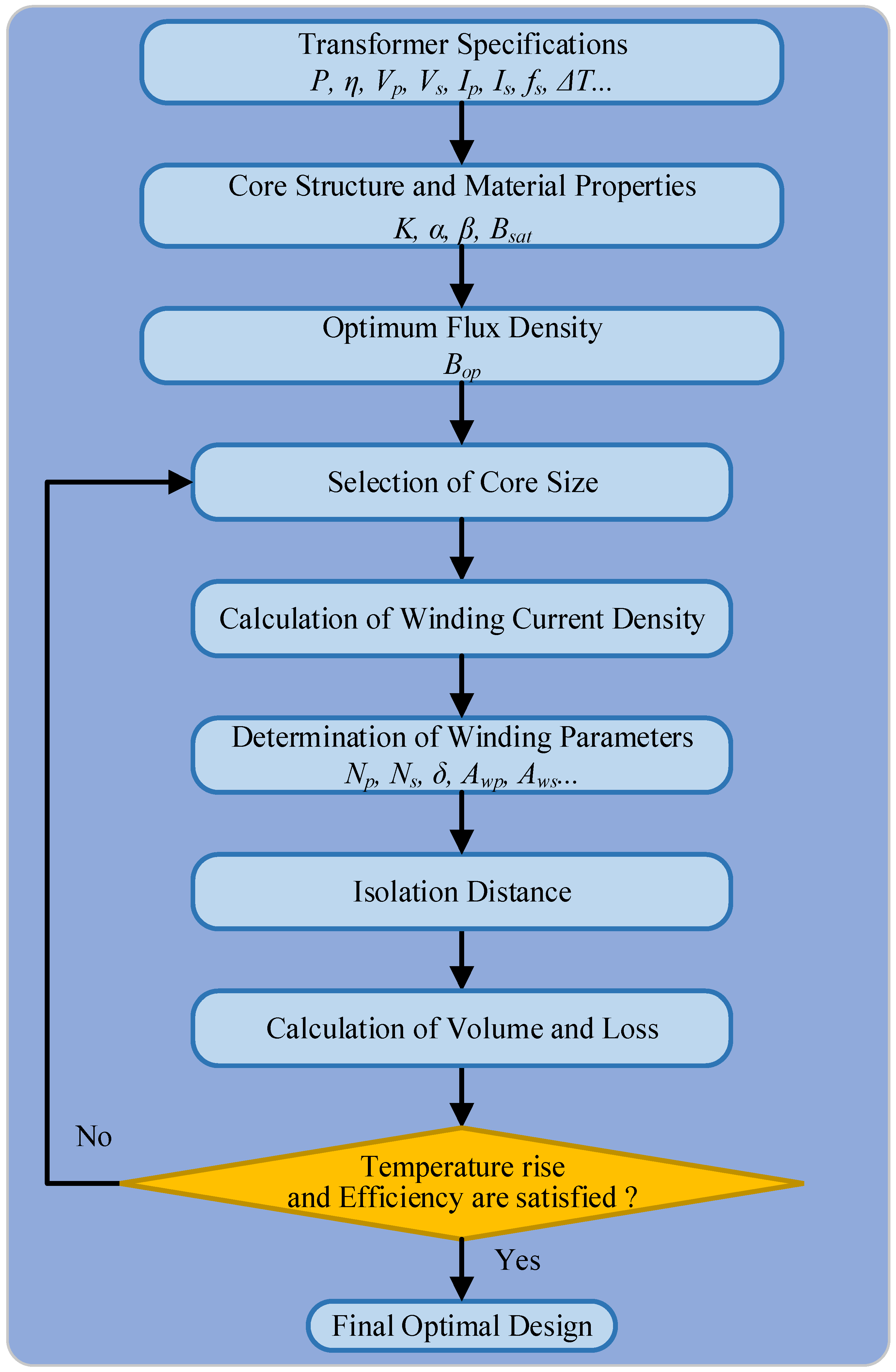
3. Design Process for the MFT

In order to reduce the cost of transformers, the design method uses the standard core and conductor available in the market due to the high cost of customized cores and conductors in this paper. The process of designing transformers will select the optimal core and windings to complete the design of MFT. The leakage inductance is usually considered to be integrated in the MFT in some design methods, however, leakage inductance integration will increase transformer losses and affect the optimal design of the transformer. Therefore, leakage inductance integration is not considered in this paper. The proposed design process for the MFT is shown in Figure 3.
Step 1: The determination of the MFT specifications, including operating voltage, current, frequency, efficiency, temperature rise, etc.
Step 2: The determination of core structure and core material properties.
Coaxial type, core type, shell type, and matrix type are four kinds of transformer core structures commonly used to construct MFT [36]. The design is based on shell type structure in this paper.
The selection of magnetic material is critical to the performance of the MFT. Different core magnetic materials have differences in loss performance, cost, mechanical strength, etc. Therefore, the choice of core material affects the efficiency, cost, and mechanical strength of the MFT.
For high-power MFT applications, four commonly used magnetic materials are ferrite, amorphous alloy, silicon steel, and nanocrystalline. The main properties of the four magnetic materials are shown in Table 1 [18,37].
Ferrite has the highest operating frequency and low core loss, but the saturation magnetic flux density is the lowest, and the ferrite core is fragile. As a result, it is not suitable for the high-power MFT design. Silicon steel material has the highest saturation flux density and low cost, but its high core loss and low operating frequency limit its application in MFTs. Nanocrystalline alloy material has superior core loss performance, but the cost is the highest. Considering mass production and application, the cost is very high.
Comparing the four core materials, the amorphous alloy material has the same operating frequency as nanocrystalline alloy material and high saturation magnetic flux density, the core loss performance and cost of which are in the middle. Finally, the amorphous alloy material is selected to design the MFT in this paper. The main parameters of the amorphous alloy material adopted are shown in Table 2.
Step 3: The optimal magnetic flux density Bop of the MFT is calculated according to (23).
Step 4: The optimal area product Ap is calculated according to (28), and the appropriate core size is selected based on the existing magnetic core model.
Step 5 and Step 6: The optimal conductor current density Jw is calculated according to Equation (27). At the same time, the appropriate Litz wire is selected based on the skin depth of the conductor according to (34). Finally, the number of the primary and secondary winding turns and the Litz wire size are determined.
Step 7: The safe isolation distance is calculated according to the voltage level.
Step 8: According to the designed core and winding parameters, the volume and loss of the MFT are recalculated.
Step 9: Determine if the design result meets the limitation of both the temperature rise and the efficiency.
Step 10: The determination of the final optimal design scheme.
Based on the optimization design method proposed above, the MFT is designed according to the transformer specifications shown in Table 3. The final design result is shown in Table 4.

4. Simulation and Experiment

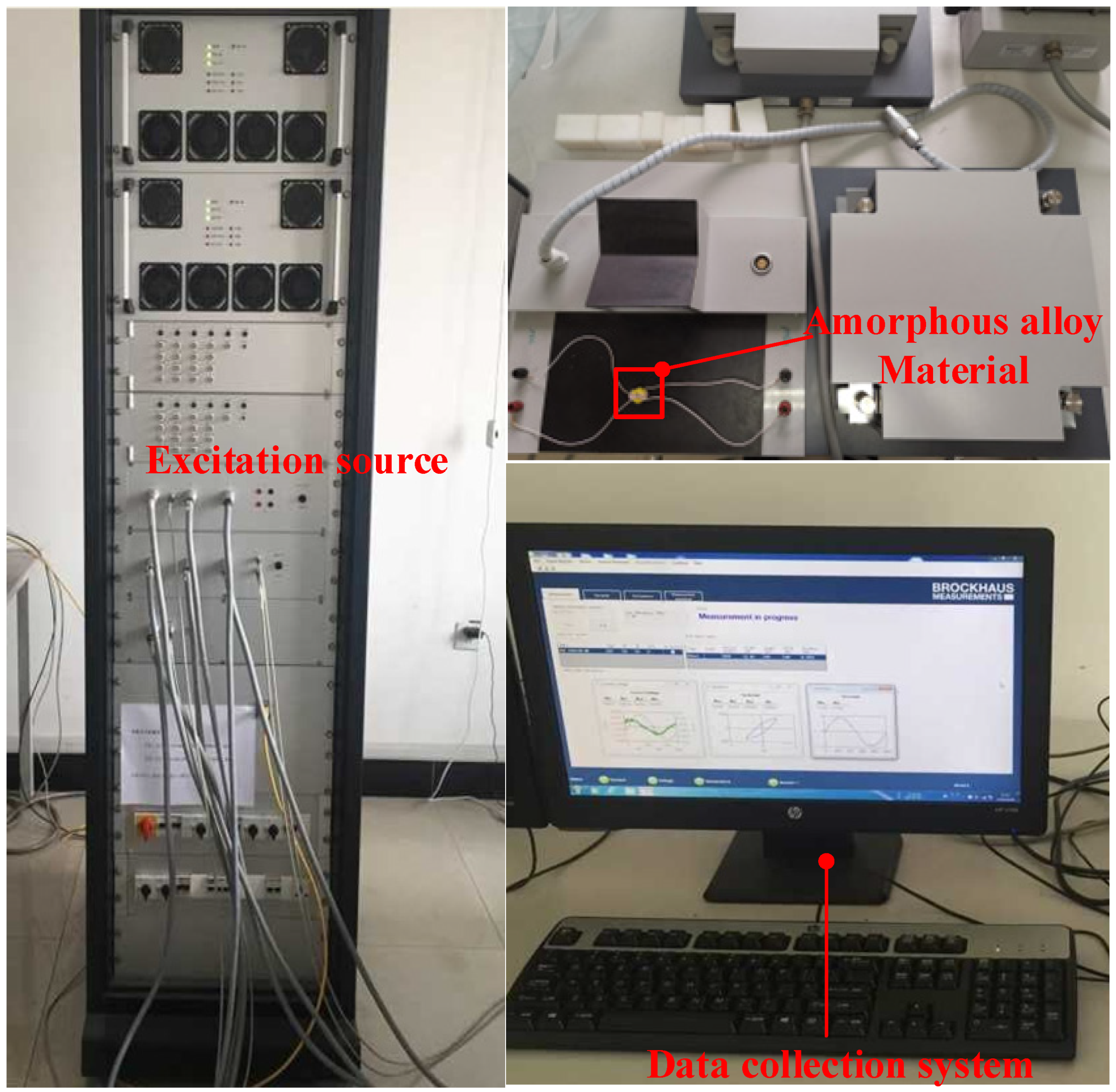
4.1. Measurement of Magnetic Material Properties

The magnetic properties of the amorphous alloy material need to be measured before simulation, and the measuring system for magnetic material properties is shown in Figure 4. Figure 5 shows the measured B-H curve at 10 kHz and the B-P curve of amorphous alloy material at different frequencies. It can be seen from Figure 5a that the saturation magnetic flux density is about 1.5 T. From Figure 5b, as the frequency of the excitation source increases, the power loss of the amorphous alloy material increases.

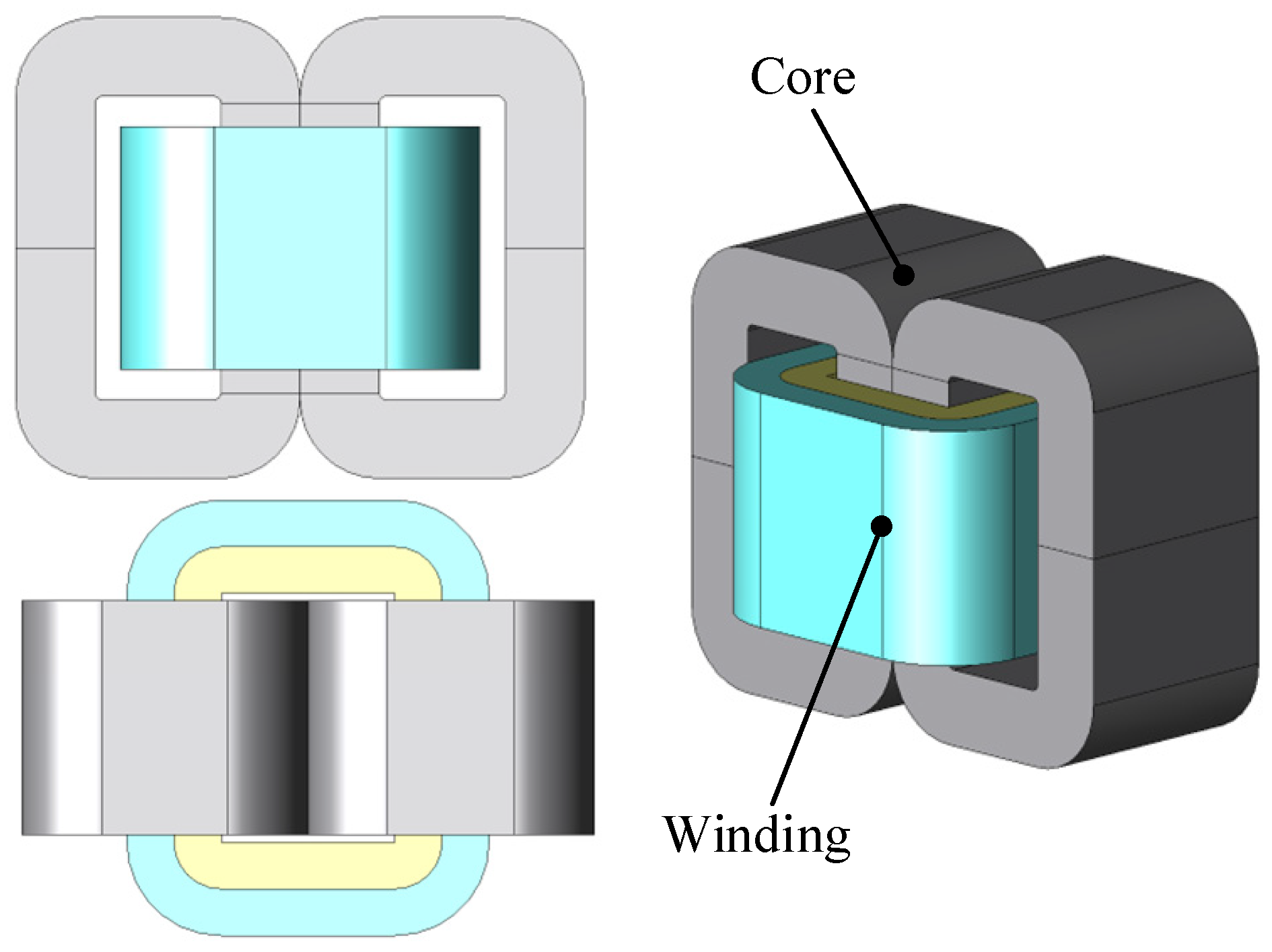
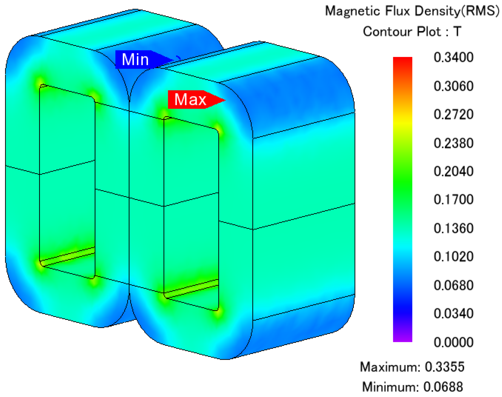
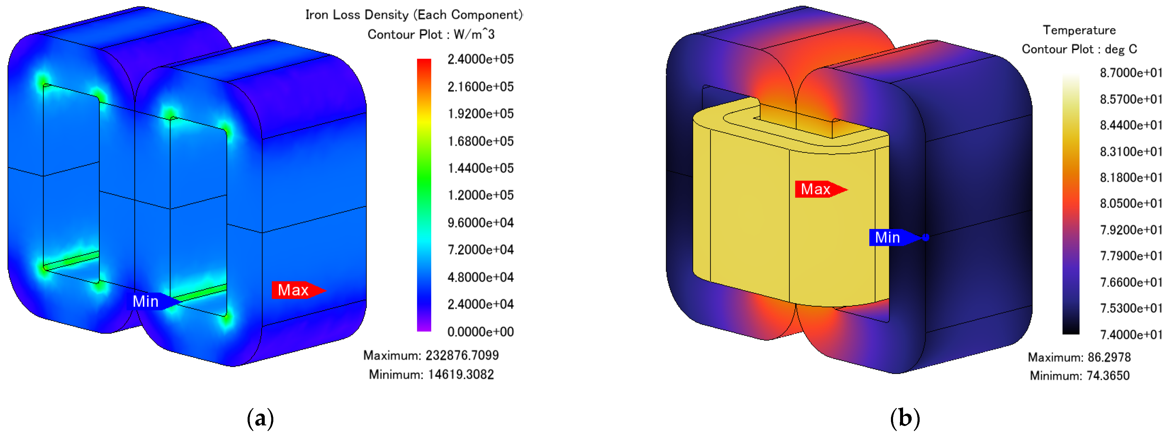
4.2. Simulation Results and Analysis

In order to verify the correctness of the designed MFT, a finite element simulation is carried out. The simulation model of the MFT is shown in Figure 6.
The magnetic flux density distribution of the MFT under rated load operation is shown in Figure 7. It can be seen from Figure 7, the maximum magnetic flux density of the MFT under rated power operation is 0.3355 T. The simulation result shows that the magnetic flux density is within a reasonable range.
The loss and temperature distribution under rated load operation are as shown in Figure 8. It can be observed that the maximum temperature of the MFT under rated load operation is about 86.3 °C which indicates the temperature rise of the MFT is reasonable.

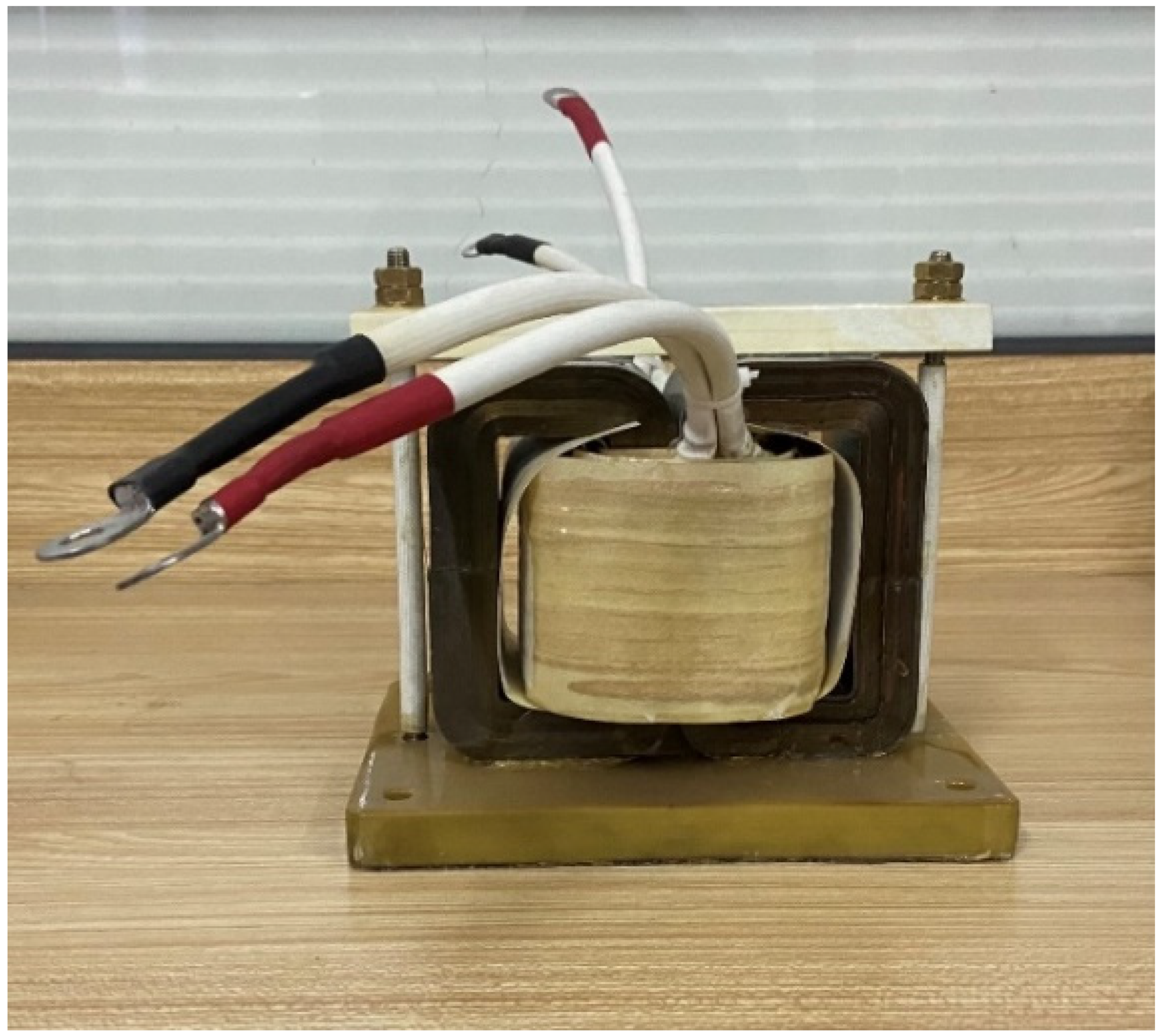
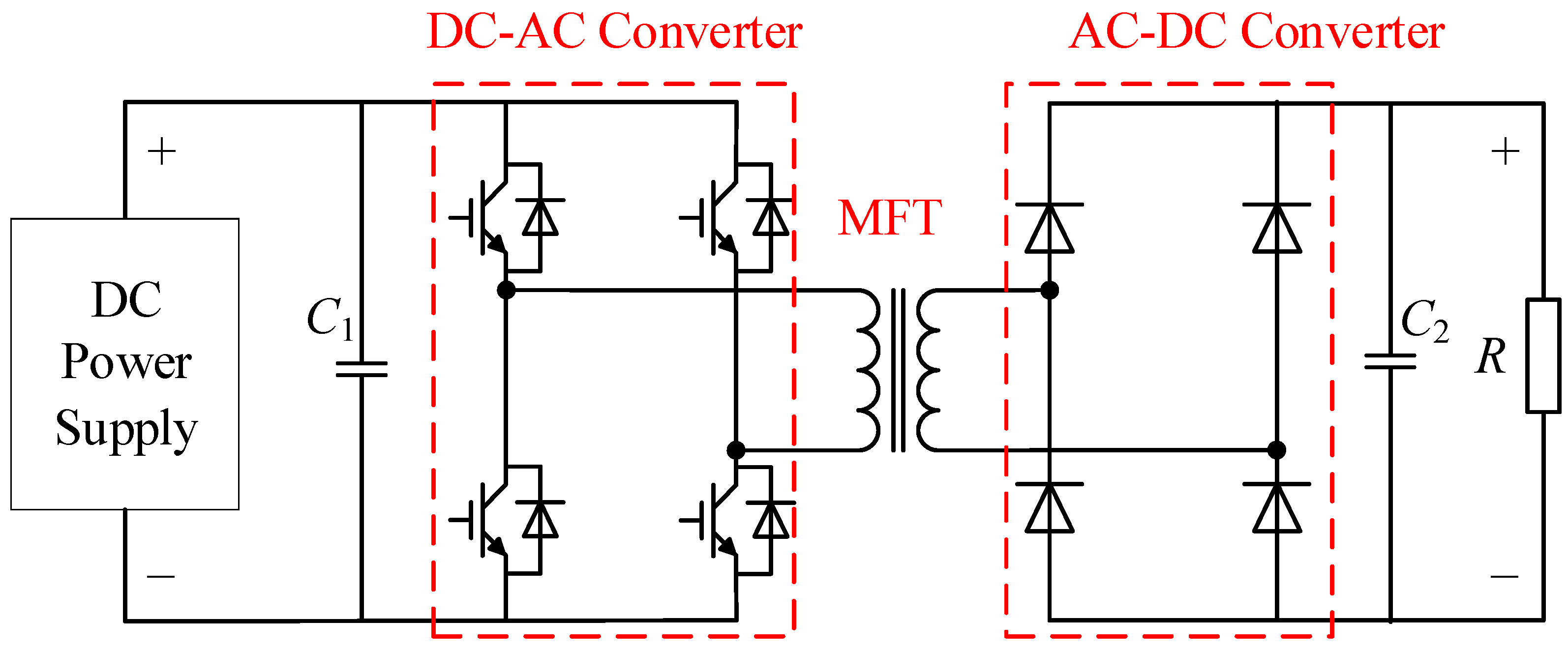
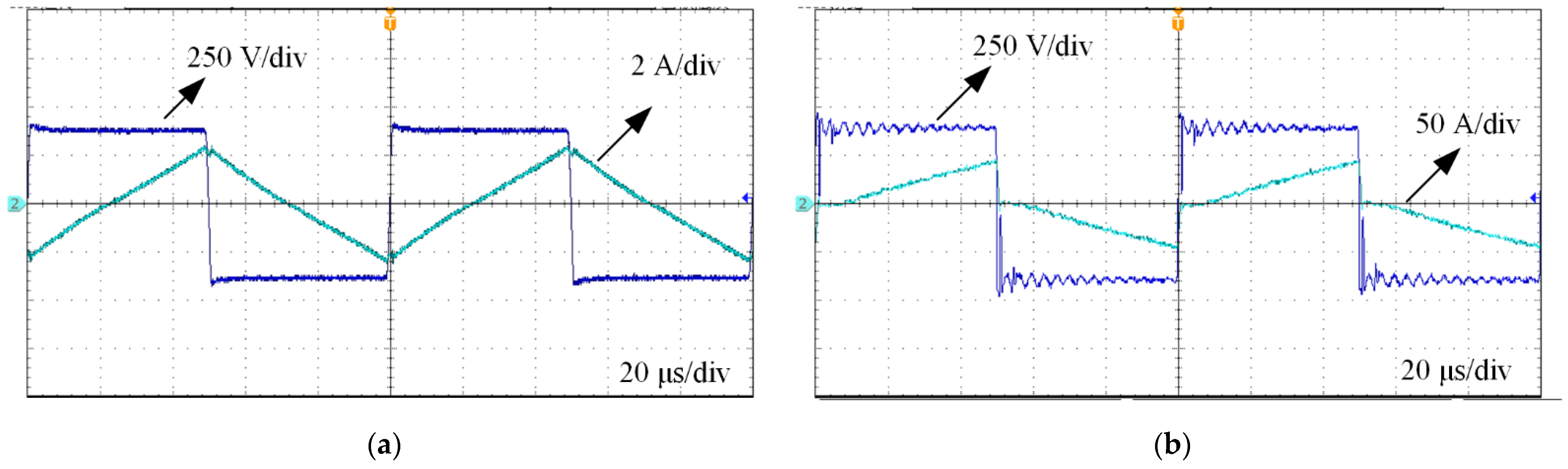
4.3. Experimental Results

According to the final design results, a shell-type 20 kW/10 kHz MFT prototype is made based on amorphous alloy material as shown in Figure 9.
In order to test the performance of the MFT prototype, the test circuit of the experimental test platform is shown in Figure 10.
According to Figure 10, the experimental test platform is built and shown in Figure 11. The DC power supply is used to regulate the voltage to obtain the required voltage value to make the MFT prototype operating at the rated voltage. An oscilloscope (Tektronix MDO3052) can record the operating voltage and current of the MFT prototype. The DC-AC converter provides the required square wave excitation for the MFT prototype.
In order to measure the core loss and open circuit temperature rise of the MFT, the MFT operates at an open-circuit operation. The secondary side of the prototype is open-circuited, and the 375 V/10 kHz square wave voltage is applied to the primary side. The voltage and current waveforms are tested on the primary side and shown in Figure 12a. To measure the temperature rise of the MFT, the MFT operates at half-load operation. The voltage and current waveforms of the MFT operating at half-load operation are shown in Figure 12b.
The measured and calculated losses of the MFT are shown in Table 5. It can be seen from the table that there is a certain error between the actual measured loss and the calculated and simulated loss. The factors that cause the error may be the transformer manufacturing process, measurement error, the effect of temperature on the loss, and the effect of the air gap on the loss.
Regarding thermal performance, the transformer is analyzed under the natural convection conditions. At 25 °C ambient temperature, the steady-state temperature distribution of the prototype under the open-circuit and half-load operation experiment is shown in Figure 13. The temperature is measured with Fluke’s infrared thermal imager. As can be seen from Figure 13, the temperature rise of the transformer is about 37 °C under the open-circuit operation and 48 °C under the half-load operation, which meets the temperature rise requirements of the MFT. It is worth mentioning that the final temperature estimate for the transformer is closely related to the experimental measurements.

5. Conclusions

In this paper, a shell-type MFT is designed based on an optimal area product design method. The amorphous alloy material is selected as the core material of the MFT because of its low cost and loss. The Litz wire is selected for the windings, which can reduce the high frequency effect. Core size and winding wire are based on the standard cores and conductors available in the market. In order to ensure the accuracy of the transformer simulation, the magnetic properties of the amorphous alloy material were measured. The finite element simulation of the designed transformer model is carried out based on the measured magnetic properties. According to the design results, a 20 kVA/10 kHz amorphous alloy MFT prototype is manufactured. The results of experimental tests verify the correctness of the MFT prototype. In future work, the nanocrystalline alloy MFT prototype will be designed and compared with the amorphous alloy one.

Author Contributions

S.Z. proposed the idea and wrote the paper; D.C. and B.B. gave technical support and conceptual advice. All authors have read and agreed to the published version of the manuscript.

Funding

This research received no external funding.

Institutional Review Board Statement

Not applicable.

Informed Consent Statement

Not applicable.

Data Availability Statement

The data that support the findings of this study are available on request from the corresponding author. The data are not publicly available due to privacy or ethical restrictions.

Conflicts of Interest

The authors declare no conflict of interest regarding the publication of this paper.

References

  1. Das, D.; Hrishikesan, V.M.; Kumar, C.; Liserre, M. Smart transformer enabled meshed hybrid distribution grid. IEEE Trans. Ind. Electron. 2020, 68, 282–292. [Google Scholar] [CrossRef]
  2. Huang, J.; Zhang, X.; Zhao, B. Simplified resonant parameter design of the asymmetrical CLLC-type DC transformer in the renewable energy system via semi-artificial intelligent optimal scheme. IEEE Trans. Power Electron. 2020, 35, 1548–1562. [Google Scholar] [CrossRef]
  3. Dragicevic, T.; Lu, X.; Vasquez, J.C.; Guerrero, J.M. DC microgrids—Part II: A review of power architectures, applications, and standardization issues. IEEE Trans. Power Electron. 2016, 31, 3528–3549. [Google Scholar] [CrossRef] [Green Version]
  4. Zhao, B.; Song, Q.; Liu, W.; Sun, Y. Overview of dual-active-bridge isolated bidirectional DC–DC converter for high-frequency-link power-conversion system. IEEE Trans. Power Electron. 2014, 29, 4091–4106. [Google Scholar] [CrossRef]
  5. Inoue, S.; Akagi, H. A bidirectional DC–DC converter for an energy storage system with galvanic isolation. IEEE Trans. Power Electron. 2007, 22, 2299–2306. [Google Scholar] [CrossRef]
  6. do Nascimento, V.C.; Moon, S.-R.; Byerly, K.; Sudhoff, S.D.; Ohodnicki, P.R. Multiobjective optimization paradigm for toroidal inductors with spatially tuned permeability. IEEE Trans. Power Electron. 2021, 36, 2510–2521. [Google Scholar] [CrossRef]
  7. Sarker, P.C.; Islam, M.R.; Guo, Y.; Zhu, J.; Lu, H.Y. State-of-the-art technologies for development of high frequency transformers with advanced magnetic materials. IEEE Trans. Appl. Supercond. 2019, 29, 7000111. [Google Scholar] [CrossRef] [Green Version]
  8. Zhao, B.; Song, Q.; Liu, W. A practical solution of high-frequency-link bidirectional solid-state transformer based on advanced components in hybrid microgrid. IEEE Trans. Ind. Electron. 2015, 62, 4587–4597. [Google Scholar] [CrossRef]
  9. Huber, J.E.; Kolar, J.W. Applicability of solid-state transformers in today’s and future distribution grids. IEEE Trans. Smart Grid 2019, 10, 317–326. [Google Scholar] [CrossRef]
  10. Bahmani, M.A.; Thiringer, T.; Rabiei, A.; Abdulahovic, T. Comparative study of a multi-MW high-power density DC transformer with an optimized high-frequency magnetics in all-DC offshore wind farm. IEEE Trans. Power Deliv. 2016, 31, 857–866. [Google Scholar] [CrossRef]
  11. Leibl, M.; Ortiz, G.; Kolar, J.W. Design and experimental analysis of a medium-frequency transformer for solid-state transformer applications. IEEE J. Emerg. Sel. Top. Power Electron. 2017, 5, 110–123. [Google Scholar] [CrossRef]
  12. Mogorovic, M.; Dujic, D. 100 KW, 10 KHz medium-frequency transformer design optimization and experimental verification. IEEE Trans. Power Electron. 2019, 34, 1696–1708. [Google Scholar] [CrossRef] [Green Version]
  13. Garcia-Bediaga, A.; Villar, I.; Rujas, A.; Mir, L.; Rufer, A. Multiobjective optimization of medium-frequency transformers for isolated soft-switching converters using a genetic algorithm. IEEE Trans. Power Electron. 2017, 32, 2995–3006. [Google Scholar] [CrossRef]
  14. Li, H.; Han, L.; He, B.; Yang, S. Application research based on improved genetic algorithm for optimum design of power transformers. In Proceedings of the Fifth International Conference on Electrical Machines and Systems—ICEMS’2001 (IEEE Cat. No.01EX501), Shenyang, China, 18–20 August 2001; Volume 1, pp. 242–245. [Google Scholar]
  15. Amoiralis, E.I.; Georgilakis, P.S.; Tsili, M.A.; Kladas, A.G. Global transformer optimization method using evolutionary design and numerical field computation. IEEE Trans. Magn. 2009, 45, 1720–1723. [Google Scholar] [CrossRef]
  16. Liang, Z.; Xie, B.; Li, R. A multi variable optimization design of high frequency transformer based on ALO algorithm. In Proceedings of the 2020 4th International Conference on HVDC (HVDC), Xi’an, China, 6–9 November 2020; pp. 670–675. [Google Scholar]
  17. Chen, B.; Liang, X.; Wan, N. Design methodology for inductor-integrated litz-wired high-power medium-frequency transformer with the nanocrystalline core material for isolated DC-link stage of solid-state transformer. IEEE Trans. Power Electron. 2020, 35, 11557–11573. [Google Scholar] [CrossRef]
  18. Rodriguez-Sotelo, D.; Rodriguez-Licea, M.A.; Soriano-Sanchez, A.G.; Espinosa-Calderon, A.; Perez-Pinal, F.J. Advanced ferromagnetic materials in power electronic converters: A state of the art. IEEE Access 2020, 8, 56238–56252. [Google Scholar] [CrossRef]
  19. Huang, P.; Mao, C.; Wang, D.; Wang, L.; Duan, Y.; Qiu, J.; Xu, G.; Cai, H. Optimal design and implementation of high-voltage high-power silicon steel core medium-frequency transformer. IEEE Trans. Ind. Electron. 2017, 64, 4391–4401. [Google Scholar] [CrossRef]
  20. Chen, D.; Cao, X.; Zhang, S.; Wang, Y.; Zhou, X.; Su, Z. Study of medium frequency transformer by using ultra-thin silicon steel sheet in DC-DC converter. IET Power Electron. 2022, 15, 789–801. [Google Scholar] [CrossRef]
  21. Zhang, P.; Li, L. Vibration and noise characteristics of high-frequency amorphous transformer under sinusoidal and non-sinusoidal voltage excitation. Int. J. Electr. Power Energy Syst. 2020, 123, 106298. [Google Scholar] [CrossRef]
  22. Johnson, F.; Hsaio, A.; Ashe, C.; Laughlin, D.; Lambeth, D.; McHenry, M.E.; Varga, L.K. Magnetic nanocomposite materials for high temperature applications. In Proceedings of the 2001 1st IEEE Conference on Nanotechnology. IEEE-NANO 2001 (Cat. No.01EX516), Maui, HI, USA, 30 October 2001; pp. 1–6. [Google Scholar]
  23. Costa, F.; Alves, F.; Benchabi, A.; Simon, F.; Lefèbvre, S. Design of a flyback transformer using a stress-annealed iron-based nanocrystalline alloy. Eur. Phys. J. AP 2002, 18, 173–180. [Google Scholar] [CrossRef]
  24. Hurley, W.G.; Wölfle, W.H. Transformers and Inductors for Power Electronics: Theory, Design and Applications; Wiley-Blackwell: Chichester, UK, 2013; ISBN 978-1-119-95057-8. [Google Scholar]
  25. Bergman, T.L.; Lavine, A.S.; Incropera, F.P.; Dewitt, D.P. Fundamentals of Heat and Mass Transfer, 7th ed.; Binder Version; Bergman, T.L., Incropera, F.P., Eds.; Wiley: Hoboken, NJ, USA, 2011; ISBN 978-0-470-91785-5. [Google Scholar]
  26. Steinmetz, C.P. On the Law of Hysteresis. Trans. Am. Inst. Electr. Eng. 1892, 9, 1–64. [Google Scholar] [CrossRef]
  27. Reinert, J.; Brockmeyer, A.; De Doncker, R.W.A.A. Calculation of losses in ferro- and ferrimagnetic materials based on the modified steinmetz equation. IEEE Trans. Ind. Appl. 2001, 37, 1055–1061. [Google Scholar] [CrossRef]
  28. Li, J.; Abdallah, T.; Sullivan, C.R. Improved calculation of core loss with nonsinusoidal waveforms. In Proceedings of the Conference Record of the 2001 IEEE Industry Applications Conference. 36th IAS Annual Meeting (Cat. No.01CH37248), Chicago, IL, USA, 30 September–4 October 2001; Volume 4, pp. 2203–2210. [Google Scholar]
  29. Venkatachalam, K.; Sullivan, C.R.; Abdallah, T.; Tacca, H. Accurate prediction of ferrite core loss with nonsinusoidal waveforms using only steinmetz parameters. In Proceedings of the 2002 IEEE Workshop on Computers in Power Electronics, Mayaguez, PR, USA, 3–4 June 2002; pp. 36–41. [Google Scholar]
  30. Shen, W. Design of High-Density Transformers for High-Frequency High Power Converters. Ph.D. Thesis, Virginia Polytechnic Institute and State University, Blacksburg, VA, USA, 2006. [Google Scholar]
  31. Orenchak, G.G. Estimating temperature rise of transformers. Power Electron. Technol. 2004, 30, 14–22. [Google Scholar]
  32. Ahmed, D.; Wang, L. Noniterative design of litz-wire high-frequency gapped-transformer (Lw-HFGT) for LLC converters based on optimal core-geometry factor model (OKGM). IEEE Trans. Ind. Electron. 2021, 68, 3090–3102. [Google Scholar] [CrossRef]
  33. Ortiz, G.; Biela, J.; Kolar, J.W. Optimized design of medium frequency transformers with high isolation requirements. In Proceedings of the IECON 2010—36th Annual Conference on IEEE Industrial Electronics Society, Glendale, AZ, USA, 7–10 November 2010; pp. 631–638. [Google Scholar]
  34. Li, J.; Water, W.; Zhu, B.; Lu, J. Integrated high-frequency coaxial transformer design platform using artificial neural network optimization and FEM simulation. IEEE Trans. Magn. 2015, 51, 8500204. [Google Scholar] [CrossRef] [Green Version]
  35. Barrios, E.L.; Ursua, A.; Marroyo, L.; Sanchis, P. Analytical design methodology for litz-wired high-frequency power transformers. IEEE Trans. Ind. Electron. 2015, 62, 2103–2113. [Google Scholar] [CrossRef]
  36. Shuai, P. Optimal Design of Highly Efficient, Compact and Silent Medium Frequency Transformers for Future Solid State Transformers. Ph.D. Thesis, ETH Zurich, Zurich, Switzerland, 2017. [Google Scholar]
  37. Rylko, M.S.; Lyons, B.J.; Hayes, J.G.; Egan, M.G. Revised magnetics performance factors and experimental comparison of high-flux materials for high-current DC–DC inductors. IEEE Trans. Power Electron. 2011, 26, 2112–2126. [Google Scholar] [CrossRef]
Figure 1. Structure of the isolated DC-DC converter.
Symmetry 14 02129 g001
Figure 2. Rectangular voltage waveform and trapezoidal flux density wave in converters.
Symmetry 14 02129 g002
Figure 3. The optimal design process for the MFT.
Symmetry 14 02129 g003
Figure 4. Measuring system for magnetic material properties.
Symmetry 14 02129 g004
Figure 5. The magnetic properties of amorphous alloy materials: (a) B-H curve; (b) B-P curve.
Symmetry 14 02129 g005
Figure 6. Simulation model of the MFT.
Symmetry 14 02129 g006
Figure 7. Magnetic flux density distribution.
Symmetry 14 02129 g007
Figure 8. Loss and temperature distribution: (a) Loss distribution; (b) Temperature distribution.
Symmetry 14 02129 g008
Figure 9. 20 kW/10 kHz MFT lab prototype.
Symmetry 14 02129 g009
Figure 10. The diagram of the experimental test platform.
Symmetry 14 02129 g010
Figure 11. Experimental test platform.
Symmetry 14 02129 g011
Figure 12. Measured voltage and current waveforms of MFT prototype: (a) Open-circuit operation; (b) Half-load operation.
Symmetry 14 02129 g012
Figure 13. Thermal image of the prototype: (a) Open-circuit operation; (b) Half-load operation.
Symmetry 14 02129 g013
Table 1. Magnetic materials properties.
Magnetic MaterialMagnetic Flux Density @25 °C [T]Operating Frequency [Hz]Rel. Permeability (100 °C @20 kHz)Curie Temperature [°C]Density [g/cm3]Core Loss @0.1 T, 20 kHz [kW/m3]Core Fill FactorRelative Cost
Ferrite
Ferroxcube-3C93
0.521 M18002404.851Low
Silicon Steel
JFE-10JNHF600
1.880.05–1 k6007007.531500.9Low
Amorphous alloy Metglas-2605SA11.560.4–150 k6003957.18700.83High
Nanocrystalline alloy
Vacuumschmelze-Vitroperm500F
1.20.4–150 k13,2006007.350.7Very high
Table 2. The Main parameters of Amorphous alloy material.
ParameterValue
K1.3617
α1.51
β1.74
Bsat1.5 T
Table 3. Design specifications of the MFT.
ParameterVariableValue
Rated PowerP20 kW
Rated Frequencyfs10 kHz
Primary VoltageVp375 V
Secondary VoltageVs375 V
Turns radion1:1
Temperature increaseΔT70 °C
Table 4. Design results of the MFT.
ParameterVariableValue
Core MaterialAmorphous Alloy METGLAS 2605SA1
Core TypeShell Type
Core DimensionsAMCC-400
Winding Wire TypeLitz Wire AWG36
Number of primary windings turnsNp18
Number of secondary windings turnsNs18
Number of primary conductor strandsSp1500
Number of secondary conductor strandsSs1500
Core lossPfe34.7 W
Windings lossPcu45.4 W
Temperature increaseΔT70 °C
Efficiencyη99.6%
Table 5. Power loss of the MFT.
ParameterWinding LossCore Loss
Calculated45.4 W34.7 W
FEM simulation63.8 W42.1 W
Measured78.8 W56.2 W
Publisher’s Note: MDPI stays neutral with regard to jurisdictional claims in published maps and institutional affiliations.

