1. Introduction
Numerous researchers are interested in the study of laminar jet flow due to its many experimental and prospective usages, such as computer cooling mechanisms, drying of spray paint on vehicles or structures, cooling jets of turbo machinery parts, the flow of sluice gate, tampering of metal and plastic sheets, etc. The estimation of the boundary layer, which is widely employed in practice, can be used to efficiently simplify the issues with laminar wall jets. The relevant non-similarity (or similarity) findings were found to be important for predicting their performances.
It is accredited that Glauert [
1] is accepted as being the first to describe the issue with the wall jet that is produced over a solid stationary wall, and provided a solution. He claims that the outside momentum flux, a quantity that is infrequently decipherable as a physical idea, is related to the second similarity restriction. Riley [
2] looked at the impact of mechanical features on a laminar wall jet. Merkin and Needham [
3,
4], and others, refined Glauert’s model by taking into account situations when both wall suction or blowing and wall motion are allowed. They discovered that, in the case of a traveling wall, the identical enlightenment could only be reached by appropriately exerting lateral suction through the requisite moveable surface. According to Magyari and Keller [
5], the second similarity limitation put forward by Glauert [
1] can be maintained via the relationship between suction and the movable wall condition. Furthermore, Cohen et al. [
6], and Xu et al. [
7] showed that original results are predominantly accessible exterior of Glauert’s model momentum limitation. It should be noted that the novel results described by Magyari and Keller [
5], and given by Cohen et al. [
8] and Xu et al. [
9], looked to be mathematically disappearing outside of the wall. Moreover, the numerical and analytical developments in the analysis of wall jet flows were considered in several articles [
10,
11,
12].
Choi [
13] invented the term nanofluids (NFs), which are aqueous dispersions of particles of up to 100 nm in size, distinguished by increasing viscosity and thermal conductivity. The transport properties of NFs are influenced by the thermophysical properties of nanoparticles and normal fluids. The addition of solid nanoparticles upsurges the normal fluid’s effective thermal conductivity, which enhances the characteristics of heat transfer (HT). In an excellent analysis, Manca et al. [
14] utilized different approaches and strategies, such as enhancing the HT surface or the factors that develop HT, and facilitating appreciably elevated heat transfer rates in a limited volume between the surface and the fluid. Cooling is an important mechanical concern that appears in numerous industries, including: microelectronics, manufacturing, transportation, and solid-state lighting. When millimeter- or micrometer-sized metal oxide or solid metal particles are added to ordinary fluids, the resulting fluid thermal conductivity rises. Zaidi and Mohyud-Din [
15] explored the analysis of Lorentz forces on the dynamics of wall jets and heat transfer flows via the approach of phase change material (PCM). Further, the features of heat transfer on wall jet nanoparticles flow with the influence of Lorentz forces were discovered by Sandeep and Animasaun [
16]. Jafarimoghaddam [
17] calculated the analytical outcome for the heat and mass transfer characteristics of the wall jet flow conveying nanofluid, while the existence of this nanofluid model was first established by Buongiorno [
18]. Mousavi et al. [
19] presented the experimental and theoretical models to present dual solutions of Casson fluid through a stretchable/shrinkable sheet induced by nanofluid with magnetic effects. They observed that the magnetic effect accelerates the velocity of the nanofluid. Dinarvand and Nejad [
20] investigated a three-dimensional (3D) flow near an off-centered stagnation point from a spinning disk stimulated by a hybrid nanofluid. Recently, Khan et al. [
21] utilized the heat transfer flow model in the presence of SAE50-ZnO nano-lubricants, where the influence of mass transpiration velocity and porous medium (PM) was significant in the presence of Glauert transformations. It was discovered that the unique numerical solutions for the existing models had varying distinct influential factors; one of the constraints, such as nanoparticles volume fraction, amplified the behavior of the temperature, however, the velocity declined.
The inertial influences and barriers, in terms of PM, which could change flow tendency or patterns along with heat transmission, are not taken into consideration by the Darcy law model. It is vital to identify the situations in which these implications are impactful. Hong et al. [
22] claim that the reference of the Brinkman [
23] model, which explains Darcy’s rule, can be additionally utilized in no-slip circumstances. Ishak et al. [
24] studied the time-independent stagnation-point flow induced by a vertical object immersed in a Darcy–Brinkman porous medium (DBPM) with a uniform wall temperature. Additionally, the buoyancy, stagnation point, and porous medium impression through a vertical plate flow were studied by Rosali et al. [
25]. They noticed the multiple branch outcomes for the phenomena of opposing as well as assisting flows. Pantokratoras [
26] scrutinized the features of forced convection and HT flow over a posited heated plane geometry embedded in DBPM. The bio-convective nanofluid flow over a heated wedge in the existence of DBPM was carefully examined by Zaib et al. [
27]. Recently, the significant role of the porous dissipation, slip effects, and frictional heating over a stretchable sheet saturated in the extended DBPM was investigated by Kausar et al. [
28].
Numerous engineering techniques rely on mixed-convection or buoyancy flow. Some transportation technologies including photovoltaic cells, nuclear reactors, semiconductors, and boilers, use a combination of free and forced convective movement. When the hydrostatic pressure caused by the thermal gradient between both the solid surface and the free stream increases and has a substantial impact on the thermal fields in addition to the flow, a mixed convective flow is necessary. Ramachandran et al. [
29] scrutinized the 2D flow across a vertical surface approaching a boundary layer under mixed convection while accounting for fluctuations in variable surface heat flux and arbitrarily high wall temperature. Multiple outcomes were found in that specific zone of flow for a particular range of buoyancy parameters, and they showed that an area of down flow was generated in the domain of oppositional flow. Devi et al. [
30] comprehend their work in the case of time-dependent flow, where the unsteady velocity of the free stream magnifies the imbalance in the flow and temperature. Ishak et al. [
31] examined the mixed convection-induced stagnation point flow and heat transfer over a permeable plate. In contrast to the frequently reported solutions for the opposing flow, it was shown that two different solutions occurred for the buoyant aiding flow.
Following the outcome of an intensive review of the literature, it is paramount to update the body of knowledge with not only the effects of rising velocity slip on the wall jet flow of water conveying alumina nanoparticles subject to irregular heat sink/source through porous medium, but also to establish a comparative analysis between the assisting and opposing nature of buoyancy forces. In addition, the similarity solutions of the boundary layer equation will be sought; according to which, the forms of the velocity distribution across the jet and the heat transfer coefficient associated with variable hot fluid at the surface of the plate are assumed. Numerical solutions were constructed for the case of assisting and opposing flows for the given models in the form of several graphs and tables showing the impact of distinct influential parameters. To the best of our knowledge, this problem has never been addressed or considered before, and the findings are new and novel.
2. Mathematical Background of the Problem
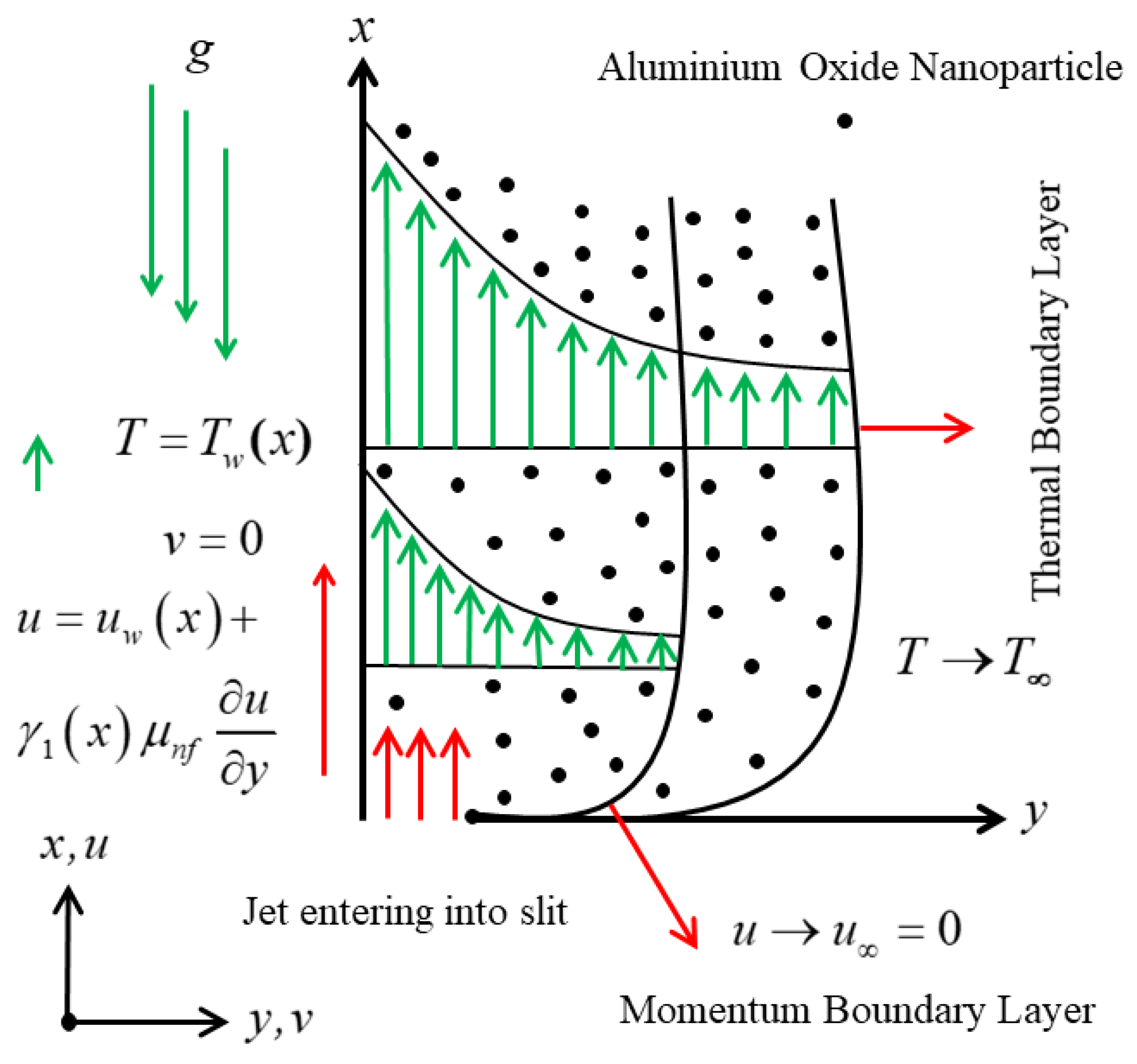
Consider the phenomenon of the wall jet flow configuration model, which is shown schematically in
Figure 1. The existing physical model is a 2D laminar mixed convective wall jet flow and heat transfer stimulated by nanofluid through a stretching and slippery surface, with the inspiration of irregular heat sink/source and Darcy–Brinkman porous medium. The assumption is that the synchronized
and
axes are represented in the posited direction of the wall and orthogonal to the geometry of the sheet, respectively. The velocity of the surface of the wall jet is taken to be the sum of the stretching velocity plus slippery velocity, and mathematically defined as
, where
is the stretching rate factor. In addition, the non-linear variable wall and far-field temperatures are denoted by
and
, respectively. Moreover,
denotes the non-uniform heat source/sink term, which is taken in the energy equation and later it is explained in detail. These presumptions enable the following leading equations (see Refs. [
1,
10]) to be obtained:
subject to the boundary conditions (BCs)
In the above equations,
and
are the respective velocity components in the requisite directions of
and
axes while
is called the nanofluid temperature. Further,
represents the slip velocity, which is mathematically defined as
, where
is the positive arbitrary constant. Further,
and
signify the permeability coefficient of the PM and the porosity parameter, respectively. Likewise, the last term
in Equation (3) illustrates the significance of an erratic or non-uniform heat sink/source as demonstrated in [
32]:
where the locus point velocity is denoted by
(see Refs. [
33,
34]). Meanwhile, the heat source/sink, similar to the temperature-dependent and the corresponding exponential decay space coefficients, are represented by the respective arbitrary constants
and
. As a result, the phenomena of a heat source correlate to the positive value of
and
, whereas the behavior of a heat sink correlates to the negative value of
and
.
In the aforementioned equations, the rest of the symbols represent the thermophysical properties of the posited nanofluid (NF). Other symbols include the thermal expansion coefficient
, viscosity
, thermal conductivity
, density
, and heat capacity
. The correlation of the NF model is given by:
The above leading equations illustrate the physical features of the water-based alumina nanofluid, where
illustrates the volume fraction of nanoparticles. Additionally,
and
are the subscript used for regular water fluid and the nanoparticles.
Table 1 contains the data of the base working fluid and alumina nanomaterials.
2.1. Similarity Procedure
Here, we include the similarity transformation procedure according to Glauert [
1] in order to analyze the given wall jet flow model under consideration:
where the stream function is represented by
. Further, in components form it is indicated by
. Therefore, the consequent components of velocity in the simple closed form may be written as:
2.2. Momentum Similarity Equation
In this portion, it is crucial to exercise Equations (10) and (11) in the leading governing Equations (1) and (2). However, Equation (1) is identically satisfied while Equation (2) is transformed to the following reduced form:
where
,
, and
represent the modified porosity, the non-dimensional permeability, and the mixed convection parameter, respectively. Additionally, the local Grashof number and the local Reynolds number are expressed by
and
, respectively.
2.3. Energy Similarity Equation
To adjust the structure of Equation (3) to a more straightforward form, Equation (5) is substituted into Equation (3), to obtain the energy equation in the following simplified form:
Additionally, we replace each term in the Equation (13) by using the well-known similarity variables (10). Thus, the following dimensionless form of equation is obtained:
where
is called the Prandtl number.
2.4. Reduced Boundary Conditions (BCs)
Equation (4) is transformed by utilizing Equation (10) to the following dimensionless form:
where
represents the velocity slip parameter and
is called the stretching parameter whose default value is fixed to be 0.01 throughout the simulations.
2.5. Engineering Quantities
This work contains two important engineering quantities: the skin friction coefficient
, and the local Nusselt number
, which are expressed as:
Now exercising Equation (10) into Equation (16), one obtains
where
,
, and
, indicate the Prandtl number, the Peclet number, and the Reynolds number, respectively.
3. Results and Discussion
This paper considers the scenario of slip effects on the dynamics of stretching wall jet and heat transfer flows through a porous medium subject to a non-uniform heat sink/source. The analysis of this problem is analyzed to observe the phenomena of assisting and opposing flows. The numerical scheme exercised here is bvp4c which is available in the MATLAB software. It operates the three-stage Lobatto formula to compute and illustrate the numerical results, which are then presented in the forms of tables and graphs. In this technique, a new set of variables are introduced to transform the higher-order ODEs into first-order ones. The numerical solutions for the influential control parameters, i.e., the nanoparticle volume fractions
, the porosity parameter
, the buoyancy parameter
, the dimensionless permeability porous medium parameter
, the velocity slip parameter
, and the irregular heat source/sink parameter
, are computed for the wall jet flow, heat transfer, friction factor, and temperature profiles. Note that for computation purposes, the following fixed or default values are used
,
,
,
,
, and
. Additionally,
Table 1 presents the data of the physical properties of the base water fluid and the nanomaterials while the comparison of the friction factor for the limiting cases is shown in
Table 2. In this comparison table, the current results are matched with the available values of the friction factor for the normal fluid with the results of Glauert [
1] and Wiani et al. [
35]. The outcomes are comparable with the available work, which gives us confidence that the present method is applicable for finding the new results. The impressions of the various factors on the dynamics of jet flow, temperature, friction factor, and heat transport phenomena are depicted graphically in
Figure 2,
Figure 3,
Figure 4,
Figure 5,
Figure 6,
Figure 7,
Figure 8,
Figure 9,
Figure 10,
Figure 11,
Figure 12,
Figure 13,
Figure 14 and
Figure 15, and quantitatively in
Table 3 and
Table 4. In addition, the analysis of the whole paper is completed to determine the circumstance of assisting flow (ASF) as well as the opposing flow (OPF). In all graphs, solid black is used for the ASF and red is used for the OPF, and can be easily differentiated.
3.1. Analysis of the Tables
Table 3 and
Table 4 elucidate the numerical output of the friction factor and heat transfer for the assisting flow (ASF; 0.003) as well as the opposing flow (OPF; −0.003) with varying values of the distinct parameters, respectively. The outcome divulges that the friction factor escalates for ASF and OPF with increasing values of
,
, and
while it reduces with greater impact of
. In addition, the friction factor is larger for the case of ASF as compared to the case of OPF. The computational quantitative data of the HT for both ASF and OPF cases are presented in
Table 4 with deviation in the impact of
and the internal heat source/sink factor. It is noted from the results that the HT augments with
and heat sink factor
while it reduces with the heat source factor
for both ASF and OPF. The heat transfer is smaller for the case of ASF as compared to the case of OPF. In other words, the heat transfer rate is escalating for both cases owing to the impact of superior values of the heat source factor, whereas the heat transfer declines due to the heat sink factor.
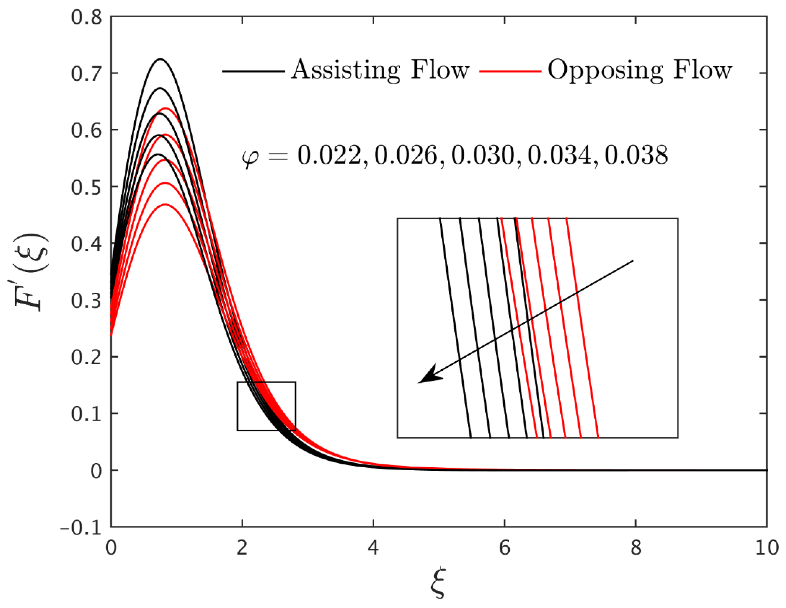
3.2. Interpretation of the Velocity Profiles
The velocity profile
for different values of
,
,
and
in the existence of the water-based alumina nanoparticles are depicted in
Figure 2,
Figure 3,
Figure 4 and
Figure 5. It is evident from these graphs that the dimensionless velocity decelerates for the diverse values of
,
, and
. Generally, a higher impact of nanoparticles makes the fluid flow phenomenon more viscous, therefore, the motion of the wall jet flow (MWJF) and MBLT shrink, as shown graphically in
Figure 2. The graphical behavior of
Figure 3 illustrates that the higher values of the porosity parameter are directly following the relation with viscosity. Increasing the porosity results in the viscosity upsurges, and in response, the motion of the wall jet flow falls for both assisting and opposing flows. However, in the specific range of
, the velocity declines and then monotonically upsurges due to the larger values of
. In addition, the velocity is approximately 1.125 higher in the vertical direction and lower by approximately 0.534 for the larger impacts of dimensionless permeability and velocity slip parameters, respectively, as shown in
Figure 4 and
Figure 5. Physically, this behavior occurs because of the stretched surface that may carry the liquid particles, which causes a decrease in the MWJF as the velocity slip factor increases. When the slip effect exists, the stream motion of the fluid near the surface is no longer equal to the speed at which the surface is stretched. Due to the limited ability of the stretching surface to communicate with the liquid under slip conditions, the fluid motion decreases, and slip velocity rises as the slip impact enhances.
3.3. Interpretation of the Temperature Profiles
The impact of parameters
,
,
,
,
, and
on the temperature profile for ASF and OPF cases in the existence of water-based alumina nanoparticles are graphically exhibited in
Figure 6,
Figure 7,
Figure 8,
Figure 9,
Figure 10 and
Figure 11, respectively.
Figure 6 shows that the curves of temperature and the thermal boundary layer thickness (TBLT) initially behave distinctly for the higher values of
and then the pattern of curves continues to increase as we move forward in the horizontal direction. The behavior of the temperature distribution is demonstrated by the inset zoom window, which shows clearly visible outcome gaps. Moreover, the TBLT is initially higher in the phenomenon of OPF and later, it increases in the case of the ASF. Physically, the improvement in the nanoparticles volume fractions leads to advancing the thermal conductivity. As a response, the behavior of the TBLT and the dimensionless temperature upsurge. The temperature profile initially upsurges in the approximate range
, and then declines abruptly for the rest of the domain for both cases owing to the higher porosity parameter as shown in
Figure 7, while the reverse pattern is observed for the superior values of
(see
Figure 8). From the mathematical expression, it is seen that the porosity parameter is inversely related to the thermal diffusivity. Thermal diffusivity is equal to the ratio of thermal conductivity to specific heat capacitance. Physically, the increase of the porosity parameter leads to a decline in thermal diffusivity. The amount of thermal conductivity is affected by this decrease in thermal diffusivity. Hence, the TBLT and the temperature profile decelerate.
Figure 9 and
Figure 10 illustrate that the profile of temperature initially boosts up, and then smoothly falls with the larger impression of the slip parameter, as well as the internal heat source factor, respectively. From both plots, it is induced that profiles are better for OPF in the range of
, and then changes to the ASF phenomenon for the rest of the domain along the horizontal direction. Generally, the existence of the heat source factor absorbs more heat in the form of energy due to the pertinent surface of the wall jet, which ultimately rises the temperature. The temperature declines and then increases for the rest of the domain with the greater impressions of the heat sink factor as shown in
Figure 11. Here, the TBLT and temperature decelerates due to less energy being absorbed in the form of heat, due to the existence of the heat sink factor. In addition, the outcome for the case of assisting flow is better than that of the opposing flow.
3.4. Interpretation of the Gradient
Figure 12 and
Figure 13 portray the drag force and the rate of heat transport in the existence of the water-based alumina nanoparticles for different values of porosity parameter
for the ASF and OPF cases, respectively. Both figures are presented against the solid nanoparticles volume fractions. The friction factor enriches the case of ASF as well as OPF due to the higher impacts of
, while heat transfer decelerates. Generally, it is seen that the thermal diffusivity of the nanoparticles slows down with the higher porosity parameter, whereas the effective viscosity increases. Firstly, higher viscosity means that the fluid nanoparticles stick on the surface of the wall, due to which the flow of the liquid stops near the surface. The flow of the posited liquid and friction factor holds the inverse proportional law. Hence, the friction factor upsurges. Secondly, the lowering of thermal diffusivity creates less thermal conductivity, which provides negligible improvement to thermal transport. Thus, the rate of heat transfer decelerates. The impressions of the dimensionless permeability parameter on the friction factor and heat transfer for ASF and OPF against the solid nanoparticle volume fractions are graphically presented in the respective
Figure 14 and
Figure 15. Likewise, the behavior of the friction factor upheavals in both cases for the higher values of
, however, the rate of heat transport loses speed in the case of assisting flow. Meanwhile, the heat transfer behaves differently for the case of opposing flow as we improve the effects of the permeability parameter. In addition, the outcomes of both gradients are higher and better for the case of assisting flow as compared to the case of opposing flow.

 ,
, 


