Article

Design and Implementation of Simplified Symmetry Chaotic Circuit

1
School of Control Science and Engineering, Shangdong University, Jinan 250200, China
2
College of Aeronautical Engineering, Binzhou Uinversity, Binzhou 256603, China
3
Shandong Engineering Research Center of Aeronautical Materials and Devices, Binzhou 256603, China
*
Author to whom correspondence should be addressed.
Symmetry 2022, 14(11), 2299; https://doi.org/10.3390/sym14112299
Submission received: 20 September 2022 / Revised: 26 October 2022 / Accepted: 26 October 2022 / Published: 2 November 2022
(This article belongs to the Special Issue Symmetry in Chaotic Systems and Circuits 2022)

Abstract

:
In order to reduce the circuit cost and improve the stability and flexibility of the circuit, a simplified symmetry chaotic circuit was designed and implemented by using an inverse integration circuit and a voltage follower as isolators. The change of different symmetry chaotic dynamic behaviors caused by the change of parameters can be realized by adjusting the time constant. The behavior coexistence characteristics and amplitude control characteristics under different initial conditions were verified. The results of circuit experiments are in good agreement with those of numerical simulation and theoretical analysis. This method is effective and feasible.

1. Introduction

Lorenz system, as the first discovered chaotic system model, has become a model for the study of nonlinear dynamic systems [1].
{ x ˙ = σ ( y x ) y ˙ = λ x y x z z ˙ = x y γ z ( σ , λ , γ ) = ( 10 , 8 3 , 28 )
In 1999, Chen et al. constructed a dual system to the Lorenz chaotic system in the sense defined by Celikovsky and Vanecek [2]. It is called the Chen chaotic system.
{ x ˙ = σ ( y x ) y ˙ = ( λ σ ) x + λ y x z z ˙ = x y γ z ( σ , γ , λ ) = ( 35 , 3 , 28 )
In 2002, Lü et al. constructed the Lü chaotic system [3], which represents the transition between the Chen chaotic system and the Lorenz chaotic system.
{ x ˙ = σ ( y x ) y ˙ = λ y x z z ˙ = x y γ z ( σ , γ , λ ) = ( 36 , 3 , 20 )
In 2008, Yang and Chen constructed the Yang and Chen chaotic system [4,5], which is a system with two stable saddle focal points and one saddle point.
{ x ˙ = σ ( y x ) y ˙ = λ x x z z ˙ = x y γ z ( σ , γ , λ ) = ( 10 , 3 , 40 )
These chaotic systems are not topologically equivalent but are closely related to each other. Other scholars have also constructed some new chaotic systems, forming a large family of chaotic systems [6,7,8,9,10].
In nonlinear systems and chaotic circuits, the design of signal sources based on chaos is currently an active research topic. Recently, using embedded systems such as FPGA (Field Programmable Gate Array), FPAA (Field Programmable Analog Array), and integrated circuit technology to realize chaotic system has become a hot topic [11,12,13]. In Ref. [11], CMOS OTA-based filters were used to realize fractional chaotic system circuits. Ref. [12] uses FPGA to realize image encryption of a chaotic system. In Ref. [13], a memristor chaotic system was realized by FPGA. Traditional chaotic system circuit is realized by using operational amplifier and capacitor to form an inverse integrator, and using operational amplifier and resistor to form an inverse summation circuit to realize linear operation. The nonlinear operation circuit is realized by multiplier and resistor. The op-amp is used to solve a differential equation for chaotic signal generation [14,15,16,17,18,19]. In Refs. [14,15,16,17,18,19], operational amplifier and capacitor are used for reverse-phase integration operation, operational amplifier is used for reverse-phase summing operation, and operational amplifier and resistance are used for inverse operation. For the 3D chaotic system circuit, at least three or four operational amplifiers are needed.
In the traditional chaotic system circuit implementation scheme, the use of too many integrated operational amplifiers composed of computing units not only makes the circuit structure more complex, but also makes the success rate of the circuit relatively low, so that the whole circuit robustness is poor [20,21,22,23]. Recently, Bkakely et al. implemented the Lorenz system circuit using a combination of two multipliers and multiple linear elements, which is a simple Lorenz circuit without the use of operational amplifiers compared to the original implementation [24]. The simplified circuit structure not only saves the cost of components, but also improves the stability of the circuit, so that the circuit has better robustness in the application [25,26]. Wu and Li used this method to implement 24 variable-boostable chaotic systems [22,26]. The method in Refs. [20,21,22,23,24,25] can only realize chaotic systems with symmetric terms, such as the Lorenz system, while for systems without symmetric terms, such as system (4), it cannot be directly realized. Based on the idea of simplified design, the system without symmetry term (4) can be realized by constructing a voltage follower with an operational amplifier, and it can also be realized by constructing a reverse-phase integrator.
Based on that simple structure, the present paper builds a symmetry chaotic system with circuit realization. Based on this idea, a simple chaotic system circuit with symmetric attractors is constructed in this paper. Instead of using at least three or four op-amps before, there is only one op-amp in this circuit.
Different from the traditional one that uses at least three or four operational amplifiers, only one operational amplifier is used to form the voltage follower or inverse integration circuit in the circuit designed in this paper to realize the chaotic system, which reduces the number of circuit components and thus reduces the design cost of the circuit. In this circuit, the combination of resistance and capacitance can be used to adjust the system parameters. Compared with the traditional circuit which only uses resistance to adjust the parameters, the flexibility of parameter design in the circuit is improved. Compared with the traditional design method, this design scheme uses less components, which improves the stability and robustness of the circuit.
The left of this paper is organized as follows. In Section 2, function analysis of circuit module. In Section 3, Lyapunov exponents spectrum and a bifurcation diagram of the symmetry chaotic system are analyzed. In Section 4, the symmetry chaotic system is realized in a simplified analog circuit. In Section 5, amplitude control of the symmetry chaotic system variables is discussed. Conclusions are drawn in the last section.

2. Function Analysis of Circuit Module

2.1. Function Analysis of the Voltage Follower and Multiplier

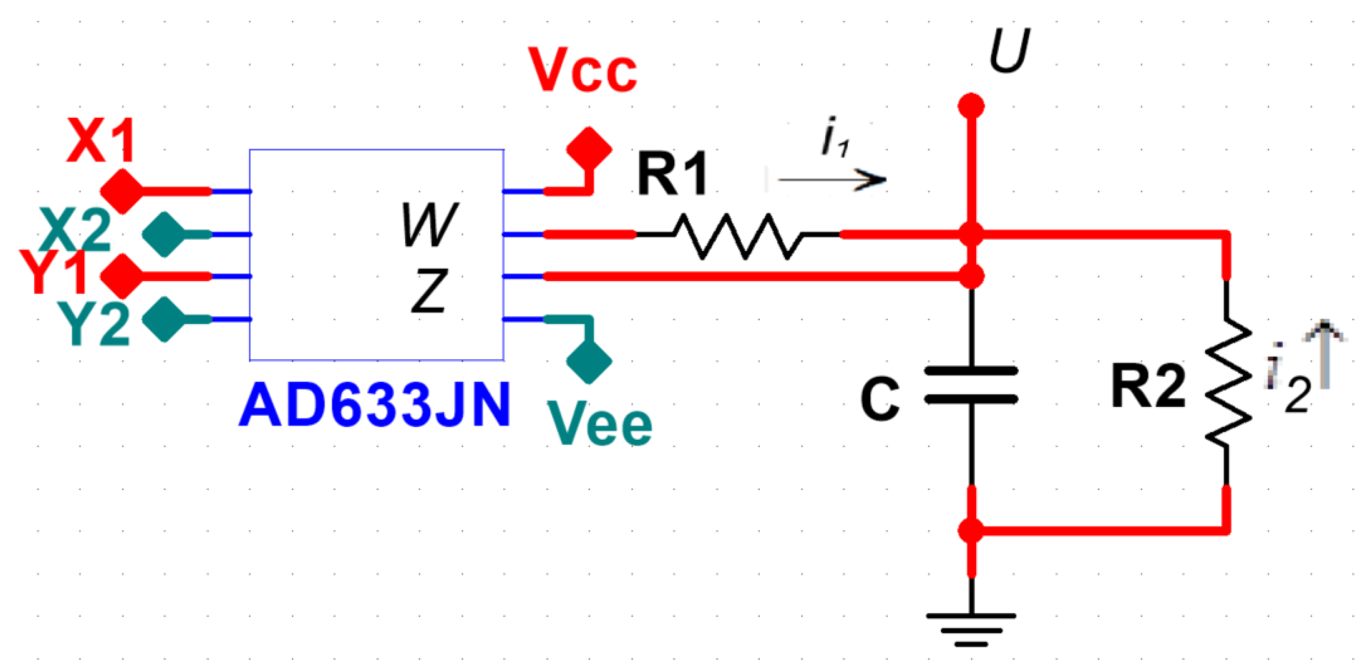
The circuit diagram of voltage follower is shown in Figure 1. Because of the “virtual break” and “virtual short” of the op amp, the output voltage V o is equal to the input voltage V i . As shown in Figure 2, using the external resistance, the multiplier AD633JN can convert the external voltage output into the external current output. The external voltage characteristic relationship of AD633JN can be expressed as: W = ( X 1 X 2 ) ( Y 1 Y 2 ) 10 + Z . If a resistor is connected in series between W and Z, the output voltage-current relationship can be expressed as: W = ( X 1 X 2 ) ( Y 1 Y 2 ) 10 + W i R . Consequently, the current equation i = ( X 1 X 2 ) ( Y 1 Y 2 ) 10 R is obtained. The equation of u ˙ = ( X 1 X 2 ) ( Y 1 Y 2 ) 10 R C is derived.

2.2. Function Analysis of the Voltage Follower Circuit as Isolators

As shown in Figure 3, the output of multiplier AD633JN connects the capacitor C 2 via resistor R 1 , the output of the capacitor u 2 connects in series with the output of the capacitor u 1 via the voltage follower and resistor R 2 . Because the input resistance of the op-amp is infinite, which is equivalent to a circuit break, the current on the resistor R flows directly into the capacitor C1, but not to the current C2. Therefore, the voltage generated by current i through R only affects capacitance C1, but not capacitance C2. When a capacitor and a multiplier are connected in series, as shown in Figure 3, the multiplier is connected through external resistor R and capacitor C2, and capacitor C2 is connected to capacitor C1 through voltage path follower and resistor R, as shown in Figure 3. From Kirchhoff’s current and voltage law, the following expression can be obtained. u ˙ = ( X 1 X 2 ) ( Y 1 Y 2 ) 10 R C is derived. When X 1 = c , X 2 = z ,   Y 1 = x ,   Y 2 = 0 , u = y , so y ˙ = ( c z ) x 10 R C .

2.3. Function Analysis of Multiplier and Resistance-Capacity Parallel Connection in Series

The multiplier is connected in parallel with capacitor C through external resistors R1 and R2, as shown in Figure 4. The following expression can be obtained from the Kilhoff law of current and voltage. u ˙ = ( X 1 X 2 ) ( Y 1 Y 2 ) 10 R 1 C 1 R 2 C u is derived. When X 1 = x , X 2 = 0 ,   Y 1 = y ,   Y 2 = 0 , u = z , so z ˙ = x y 10 R 1 C 1 R 2 C z .

2.4. Function Analysis of the Inverse Integration Circuit as Isolators

As shown in Figure 5, the output u2 of the op-amp is connected in series to another output u1 through the resistor R2. Because the op-amp output resistance is very small, equivalent to a circuit short circuit, the output from the output u1 on the reverse current i, through the resistance R2, flow to the op-amp, but not to the capacitor C2. Therefore, the voltage generated by current i through R only affects capacitance C1, but not capacitance C2.
The multiplier and the inverse integration circuit connect in series as isolators, as shown in Figure 5. From the current balance under Kirchhoff’s Law, the equation of u ˙ 2 = ( X 1 X 2 ) ( Y 1 Y 2 ) 10 R 1 C 2 , u ˙ 1 = u 2 u 1 R 1 C 1 is derived, When X 1 = 0 , X 2 = x ,   Y 1 = c ,   Y 2 = 0 , u 1 = x , u 2 = y ,so x ˙ = y x R 1 C 1 , y ˙ = ( c z ) x 10 R 1 C 2 .

3. Bifurcation Analysis of Lyapunov Exponents Spectrum and Bifurcation Diagram

As a and b vary, the dynamics of system (4) are further researching by phase portrait, bifurcation diagram, Lyapunov exponents spectrum, and so on. In the following matalb solution, when the initial condition is (2,2,2) and the time interval is 0.001, the Runge–Kutta method of order 4–5 is adopted to solve the differential equation. The three Lyapunov exponents of system (4) are denoted by L 1 , L 2 , L 3 and L 1 > L 2 > L 3 .

3.1. Fixing a = 10 , c = 40 and Varying b

The Lyapunov exponents spectrum of state variable x of system (4) with respect to parameter b is shown in Figure 6a. The corresponding bifurcation diagram is given in Figure 6b. It is clear that the Lyapunov exponents spectrum coincides well with the bifurcation diagram.
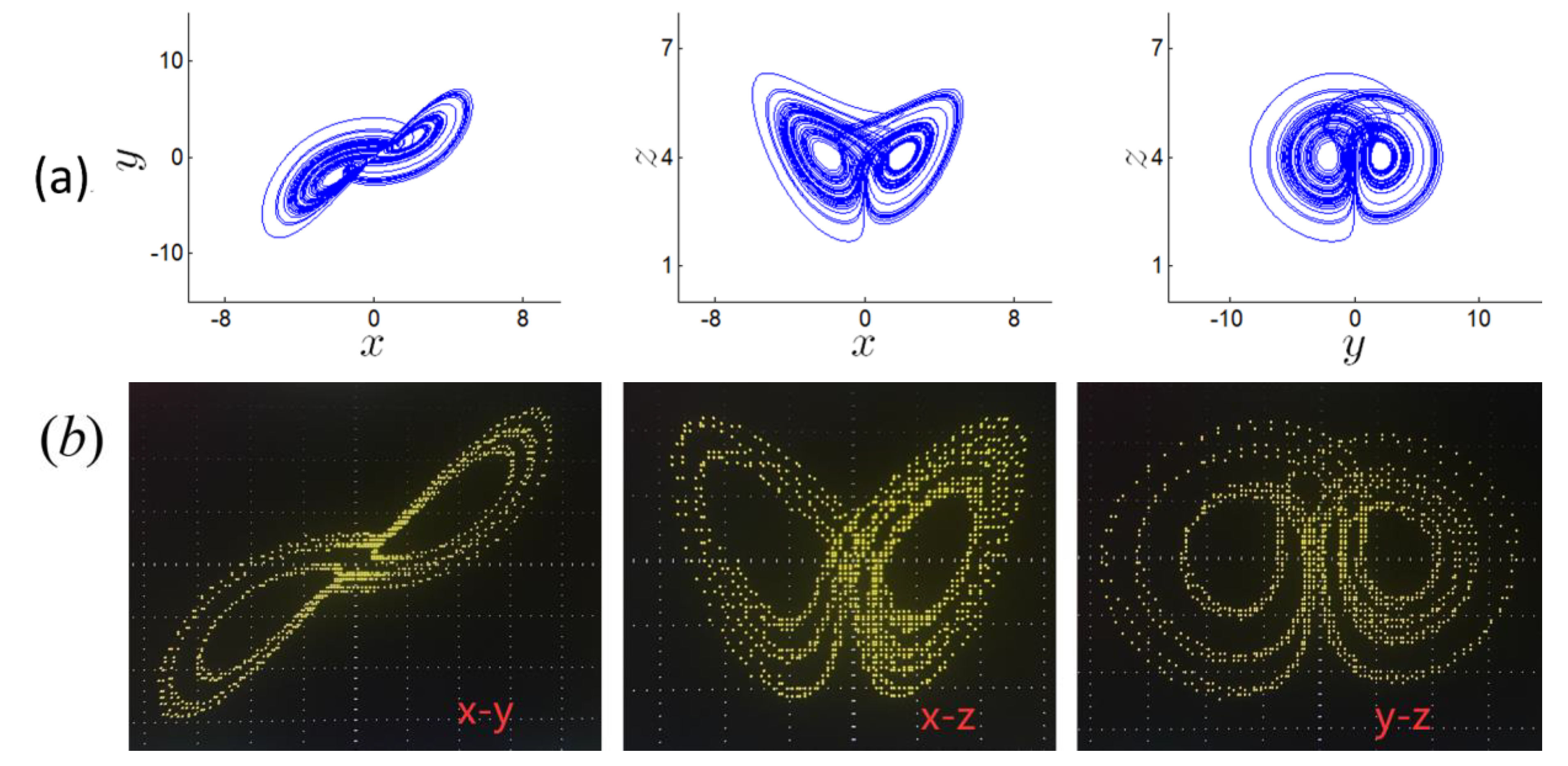
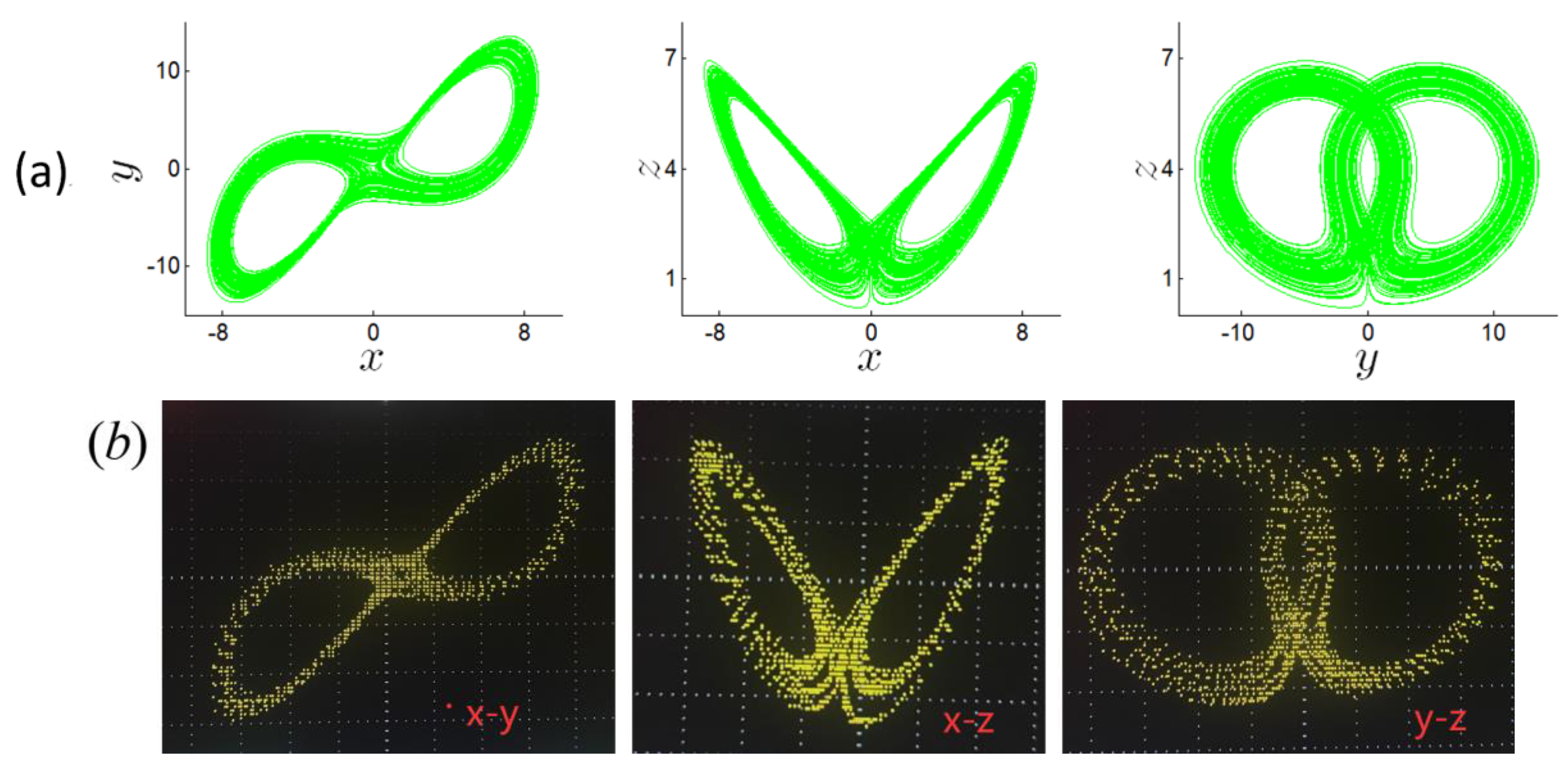
When b [ 1 , 6 ] , L 1 > 0 , L 2 = 0 and L 3 < 0 , and symmetry chaotic attractors will appear. When b = 1 , 2 , 3.5 , 5 and 6 , some chaotic attractors are shown in Figure 7a, Figure 8a, Figure 9a, Figure 10a and Figure 11a, respectively, with corresponding Lyapunov exponents shown in Table 1.

3.2. Fixing b = 3 , c = 40 and Varying a

Figure 12 shows the bifurcation diagram and the Lyapunov exponent spectrum of system (4) with respect to parameter a . Obviously, the Lyapunov exponents spectrum coincides well with the bifurcation diagram.
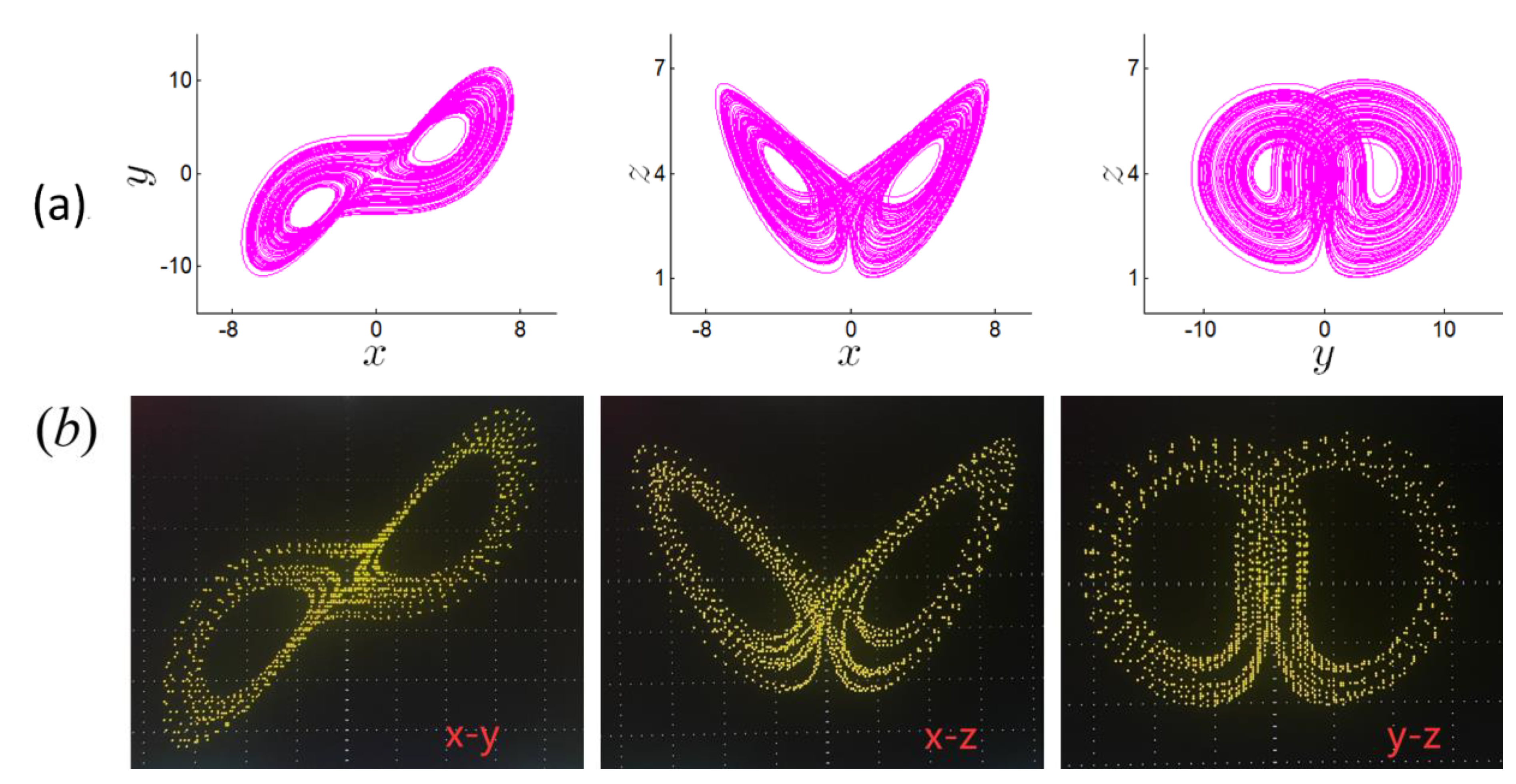
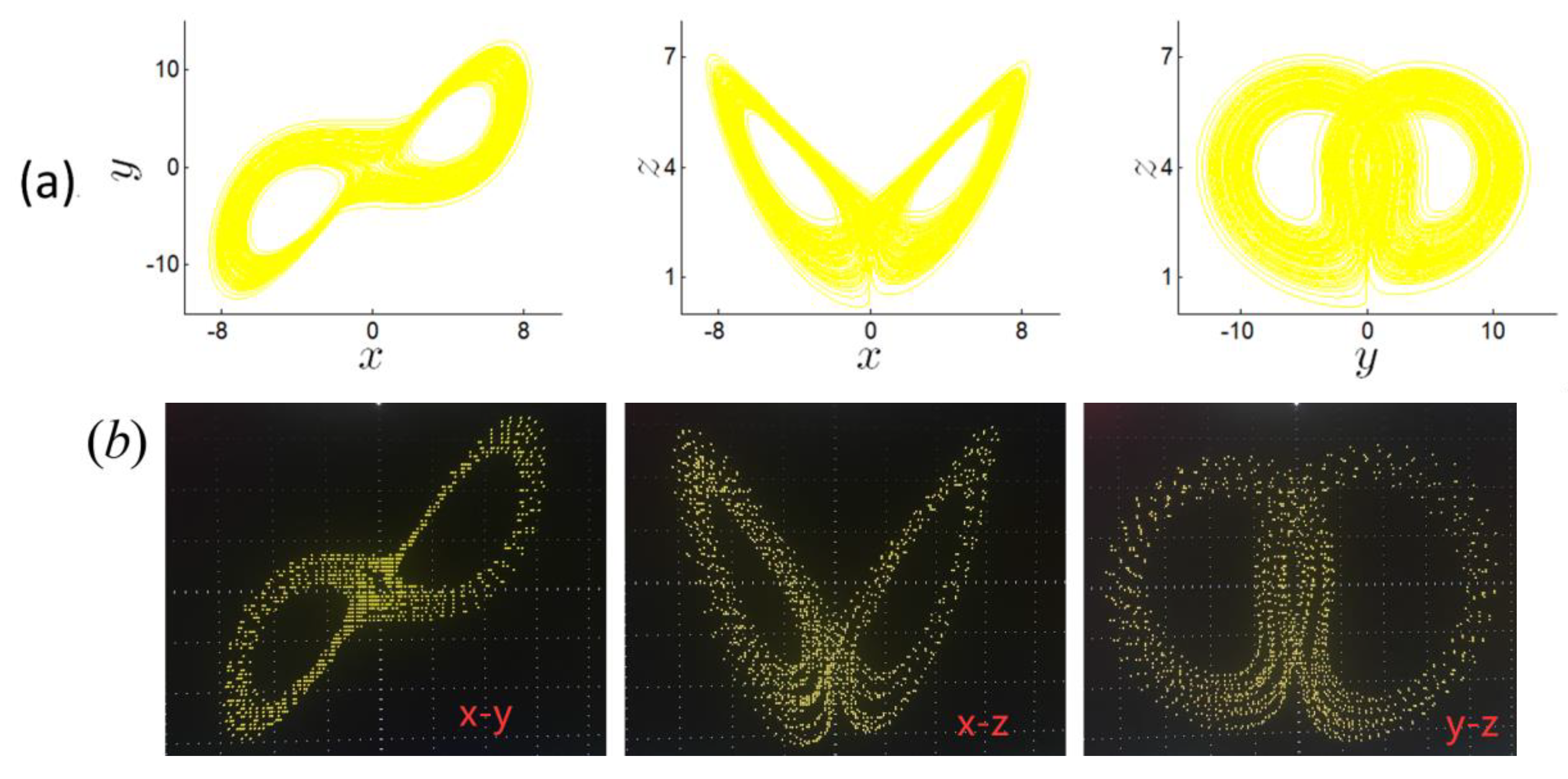
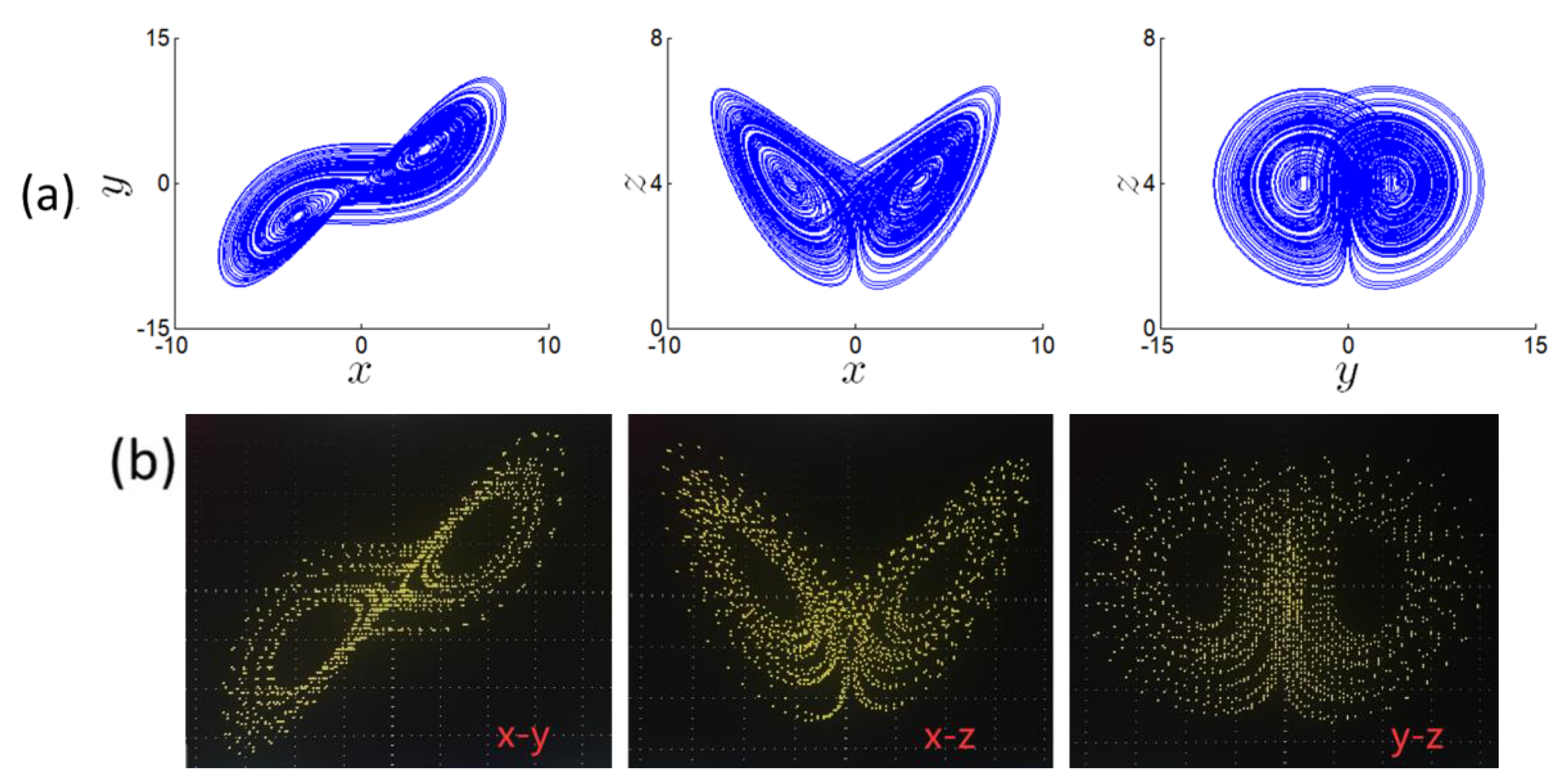
When a [ 3 , 15 ] , L 1 > 0 , L 2 = 0 and L 3 < 0 , symmetry chaotic attractors will appear. When a = 3.75 , 7.5 , 12 and 15 , some chaotic attractors are shown in Figure 13a, Figure 14a, Figure 15a and Figure 16a, respectively, with corresponding Lyapunov exponents shown in Table 2.

4. Simplified Circuit Realization and Experimental Results

The realization of chaos circuit is the basis of chaos application in engineering practice. In this part, using two multipliers, one operational amplifier, and some passive components, based on the design idea of simplified circuit, a simplified chaotic circuit was designed to realize system (4). Through the external resistance of the multiplier, the voltage is converted into current. According to Kirchhoff’s current law, the voltage summation operation is realized by the capacitor integration, and the voltage product operation is realized by the multiplier.
The operational amplifier LF347BN, the multiplier AD633JN, has a scale factor of 0.1. The positive and negative poles were connected with V C C and V E E , respectively.

4.1. Simplified Circuit Realization Based on Voltage Follower

Taking advantage of some external voltage input characteristics of the multiplier, the system (4) is implemented in a simplified circuit based on voltage follower, as shown in Figure 17.
According to system (4), the circuit equation is described by
{ d x d t = 1 R 2 C 1 ( y x ) d y d t = ( V 1 z ) x 10 R 1 C 2 d z d t = x y 10 R 3 C 3 1 R 4 C 3 z
All capacitance are set to 10   nF , according to the Equations (4) and (5), and we set R 1 = 1   , R 2 = 10   , R 3 = 10   , V 1 = 4 in Figure 17. The equation is transformed as follows:
{ d x d τ = 10 ( y x ) d y d τ = 40 x 10 x z d z d τ = x y 100 R 4 z
When R 4 = 100   , it is b = 1 , the circuit experimental results obtained from oscilloscopes are shown in Figure 7b. When R 4 = 50   , it is b = 2 , the circuit experimental results obtained from oscilloscopes are shown in Figure 8b. When R 4 = 28.5   , it is b = 3.5 , and the circuit experimental results obtained from oscilloscopes are shown in Figure 9b. When R 4 = 20   , it is b = 5 , and the circuit experimental results obtained from oscilloscopes are shown in Figure 10b. When R 4 = 16.7   , it is b = 6 , and the circuit experimental results obtained from oscilloscopes are shown in Figure 11b. It is obvious that the numerical simulation results matched well with the circuit experimental results.

4.2. Simplified Circuit Realization Based on Inverse Integration

The circuit simulation of the chaotic system could be realized. For time scaling factors τ = 100 t , Equation (4) can be written as follows:
{ d x d τ = 100 a ( y x ) d y d τ = 100 c x 100 x z d z d τ = 100 x y 100 b z
The analog circuit is shown in Figure 18, from which the state equations can be obtained as follows:
{ d x d t = 1 R 2 C 1 ( y x ) d y d t = ( V 1 z ) ( x ) 10 R 1 C 2 d z d t = x y 10 R 3 C 3 1 R 4 C 3 z
Supposing that the coefficients in Equation (7) are equal to the corresponding ones in Equation (8), the above equations can be written as follows:
1 R 2 C 1 = 100 a , V 1 R 1 C 2 = 100 c , 1 R 1 C 2 = 10 , 1 R 3 C 3 = 100 , 1 R 3 C 3 = 100 b
The specific resistance parameters and capacitance parameters were set as C 1 = C 2 = C 3 = 100   nF , R 1 = 1   , R 3 = 10   , R 4 = 33.3   , and the resistance parameters could be calculated as: When a = 3.75 , it is R 2 = 2.67   , the circuit experimental results obtained from oscilloscopes are shown in Figure 13b. When a = 7.5 , it is R 2 = 1.35   , and the circuit experimental results obtained from oscilloscopes are shown in Figure 14b. When a = 12 , it is R 2 = 0.83   , and the circuit experimental results obtained from oscilloscopes are shown in Figure 15b. When a = 3.75 , it is R 2 = 0.67   , and the results obtained from oscilloscopes are shown in Figure 16b. As can be seen from Figure 13b to Figure 16b, the results of circuit experimental are consistent with the results of the numerical simulations, shown from Figure 13a to Figure 16a.

4.3. The Frequency Behavior of the System (4)

The frequency of the circuit can be increased by reducing the capacitance in it. When a = 10 , b = 3 , c = 40 , the C 1 = C 2 = C 3 = 100   nF and C 1 = C 2 = C 3 = 68   nF , respectively, the x variable FFT of the chaotic waveforms of Figure 17 are shown in Figure 19a,b. When a = 10 , b = 3 , c = 40 , the C 1 = C 2 = C 3 = 47   nF and C 1 = C 2 = C 3 = 22   nF , respectively, the x variable FFT of the chaotic waveforms of Figure 17 are shown in Figure 19c,d.
From Figure 19, it can be seen that the frequency gradually increases with the decrease of capacitance value. Therefore, it is possible to increase the frequency of the circuit by reducing the capacitance value in the circuit.

5. Amplitude Control by a Single Parameter

For a dynamic system, there are many parameters that affect its dynamic characteristics, some of which affect the bifurcation characteristics, and some of which do not. The Yang–Chen chaotic system introduces only a quadratic term with a parameter to adjust the amplitude. When a = 10 , b = 3 , c = 40 , let x ( x / m ) , y ( y / m ) , z z , system (4) turns to be,
{ x ˙ = a ( y x ) y ˙ = c x 10 x z z ˙ = m x y b z
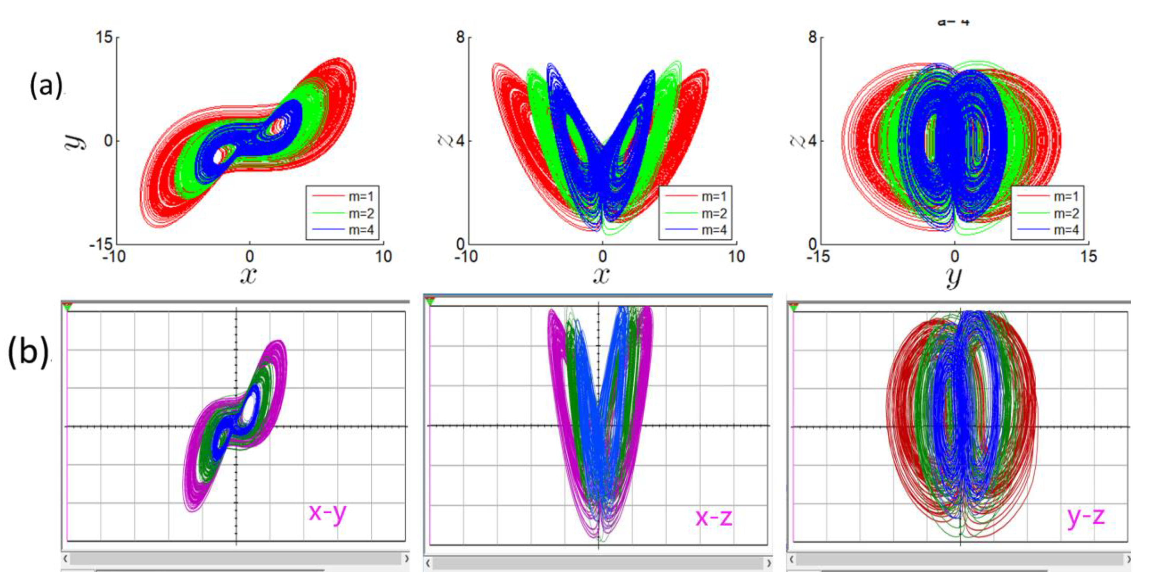
the parameter m makes the state variables x , y rescaled by the parameter m , but cannot control the state variable z . As shown in Figure 20a, parameter m has basically the same influence on the amplitude of system state variables x , y .
The mean of the absolute value of the state variable decreases as m increases, but when the parameter m changes in the range of [ 0 5 ] , the Lyapuov exponent spectrum remains constant, as shown in Figure 21. The controlled amplitude can be clearly seen from the attractor, as shown in Figure 21a. Figure 21 shows that the amplitude of the attractor has a negative proportion with the parameter m .
When m = 1 , it is R 3 = 10   , and m = 2 , it is R 3 = 5   , and m = 4 , it is R 3 = 2.5   , the experimental results obtained from oscilloscopes are shown in Figure 20b. Figure 20b shows that the amplitude of x , y is controlled by adjusting resistance R 3 .

6. Conclusions

In this paper, through the external input of multiplier, using voltage follower circuit and inverse integrator circuit, the circuit of simplified chaotic system is realized. The dynamic characteristics of the system were analyzed by Lypunaov exponential spectrum and bifurcation diagram, and numerical simulation was carried out. The circuit experimental results are consistent with the numerical simulation results. The simplified circuit regulates the amplitude through resistance to obtain chaotic signals with controllable amplitude. The main disadvantages of this paper are: (1) the bias voltage of the components used is relatively high, and the power consumption is large. (2) The frequency of the generated signal is relatively low. Simplifying the circuit reduces the number of components, reduces the cost of the circuit, improves the stability and flexibility of the circuit, and provides strong technical support for the application of chaotic systems in information encryption and other engineering practices.
Further research needs to consider possible applications of this simple chaotic system.

Author Contributions

Conceptualization, Z.W.; methodology, Z.W.; software, Z.W.; validation, Z.W. and S.L.; formal analysis, Z.W. and S.L.; investigation, Z.W. and S.L.; resources, Z.W. and S.L.; data curation, Z.W.; writing—original draft preparation, Z.W. and S.L.; writing—review and editing, Z.W. and S.L.; visualization, Z.W. and S.L.; supervision, Z.W. and S.L.; project administration, Z.W. All authors have read and agreed to the published version of the manuscript.

Funding

This work was supported the Natural Science Foundation of Shandong Province (Grant No.: ZR2014FQ019), the Key Research and Development Plan of Shandong Province (Grant No.: 2017GGX10132).

Data Availability Statement

The data used to support the findings of this study are available from the corresponding author upon request.

Conflicts of Interest

The authors declare no conflict of interest.

References

  1. Lorenz, E.N. Deterministic non-perodic flows. Atoms. Sci. 1963, 20, 130. [Google Scholar] [CrossRef]
  2. Chen, G.; Ueta, T. Yet another chaotic attractor. Int. J. Bifurc. Chaos 1999, 9, 1465–1466. [Google Scholar] [CrossRef]
  3. Lü, J.; Chen, G. A new chaotic attractor coined. Int. J. Bifurc. Chaos 2002, 12, 659–661. [Google Scholar] [CrossRef] [Green Version]
  4. Yang, Q.; Chen, G.; Zhou, T. A Unified Lorenz-Type System and its Canonical Form. Int. J. Bifurc. Chaos 2006, 16, 2855–2871. [Google Scholar] [CrossRef]
  5. Yang, Q.; Chen, G. A Chaotic System with One saddle and Two Stable Node-Foci. Int. J. Bifurc. Chaos 2008, 18, 1393–1414. [Google Scholar] [CrossRef]
  6. Liu, C.; Liu, T.; Liu, L.; Liu, K. A new chaotic attracator. Chaos Solitons Fractals 2004, 22, 1031–1038. [Google Scholar] [CrossRef]
  7. Wang, G.-Y.; Qiu, S.-S.; Li, H.-W.; Li, C.-F.; Zheng, Y. A new chaotic system and its circuit realization. Chin. Phys. B 2006, 15, 2872–2877. [Google Scholar]
  8. Li, C.; Sprott, J.C.; Joo-Chen Thio, W.; Gu, Z. A simple memristive jerk system. IET Circuits Devices Syst. 2020, 15, 383–392. [Google Scholar] [CrossRef]
  9. Song, Y.; Yuan, F.; Li, Y. Coexisting Attractors and Multistability in a Simple Memristive Wien-Bridge Chaotic Circuit. Entropy 2019, 21, 678. [Google Scholar] [CrossRef] [Green Version]
  10. Mello, L.F.; Messias, M.; Braga, D.C. Bifurcation analysis of a new Lorenz-like chaotic system. Chaos Solitons Fractals 2008, 37, 1244–1255. [Google Scholar] [CrossRef]
  11. Valencia-Ponce, M.A.; Castañeda-Aviña, P.R.; Tlelo-Cuautle, E.; Carbajal-Gómez, V.H.; González-Díaz, V.R.; Sandoval-Ibarra, Y.; Nuñez-Perez, J.C. CMOS OTA-based filters for designing fractional-order chaotic oscillators. Fractal Fract. 2021, 5, 122. [Google Scholar] [CrossRef]
  12. Sambas, A.; Vaidyanathan, S.; Zhang, X.; Koyuncu, I.; Bonny, T.; Tuna, M.; Alçin, M.; Zhang, S.; Sulaiman, I.M.; Awwal, A.M.; et al. A Novel 3D Chaotic System with Line Equilibrium: Multistability, Integral Sliding Mode Control, Electronic Circuit, FPGA Implementation and Its Image Encryption. IEEE Access 2022, 10, 68057–68074. [Google Scholar] [CrossRef]
  13. Mohamed, S.M.; Sayed, W.S.; Radwan, A.G.; Said, L.A. FPGA Implementation of Reconfigurable CORDIC Algorithm and a Memristive Chaotic System with Transcendental Nonlinearities. IEEE Trans. Circuits Syst. I Regul. Pap. 2022, 69, 2885–2892. [Google Scholar] [CrossRef]
  14. Yu, W.; Wang, J.; Wang, J.; Zhu, H.; Li, M.; Li, Y.; Jiang, D. Design of a new seven-dimensional hyperchaotic circuit and its application in secure communication. IEEE Access 2019, 7, 125586–125608. [Google Scholar] [CrossRef]
  15. Wang, X.; Zhang, X.; Gao, M. A Novel Voltage-Controlled Tri-Valued Memristor and Its Application in Chaotic System. Complexity 2020, 2020, 6949703. [Google Scholar] [CrossRef]
  16. Chang, H.; Li, Y.; Chen, G.; Yuan, F. Extreme Multistability and Complex Dynamics of a Memristor-Based Chaotic System. Int. J. Bifurc. Chaos 2020, 30, 2030019. [Google Scholar] [CrossRef]
  17. Wang, X.; Jin, C.; Min, X.; Yu, D.; Iu, H.H.C. An exponential chaotic oscillator design and its dynamic analysis. IEEE/CAA J. Autom. Sin. 2020, 7, 1081–1086. [Google Scholar] [CrossRef]
  18. Xiu, C.; Zhou, R.; Liu, Y. New chaotic memristive cellular neural network and its application in secure communication system. Chaos Solitons Fractals 2020, 141, 110316. [Google Scholar] [CrossRef]
  19. Li, Y.; Li, C.; Zhang, S.; Chen, G.; Zeng, Z. A Self-Reproduction Hyperchaotic Map with Compound Lattice Dynamics. IEEE Trans. Ind. Electron. 2022, 69, 10564–10572. [Google Scholar] [CrossRef]
  20. Jia, H.Y.; Chen, Z.Q.; Qi, G.Y. Chaotic Characteristics Analysis and Circuit Implementation for a Fractional-Order System. Circuits Syst. I Regul. Pap. IEEE Trans. 2014, 61, 845–853. [Google Scholar] [CrossRef]
  21. Li, Y.; Zhao, M.; Geng, F. Dynamical Analysis and Simulation of a New Lorenz-Like Chaotic System. Math. Probl. Eng. 2021, 2021, 6669956. [Google Scholar] [CrossRef]
  22. Li, C.; Sprott, J.C. Variable-boostable chaotic flows. Optik 2016, 127, 10389–10398. [Google Scholar] [CrossRef]
  23. Tsafack, N.; Kengne, J.; Abd-El-Atty, B.; Iliyasu, A.M.; Hirota, K.; Abd EL-Latif, A.A. Design and implementation of a simple dynamical 4-D chaotic circuit with applications in image encryption. Inf. Sci. 2020, 515, 191–217. [Google Scholar] [CrossRef]
  24. Blakely, J.N.; Eskridge, M.B.; Corron, N.J. A simple Lorenz circuit and its radio frequency implementation. Chaos 2007, 17, 023112. [Google Scholar] [CrossRef] [PubMed]
  25. Wu, J.; Li, C.; Ma, X.; Lei, T.; Chen, G. Simplification of Chaotic Circuits with Quadratic Nonlinearity. IEEE Trans. Circuits Syst. II Express Briefs 2022, 69, 1837–1841. [Google Scholar] [CrossRef]
  26. Jiang, Y.; Li, C.; Liu, Z.; Lei, T.; Chen, G. Simplified Memristive Lorenz Oscillator. IEEE Trans. Circuits Syst. II Express Briefs 2022, 69, 3344–3348. [Google Scholar] [CrossRef]
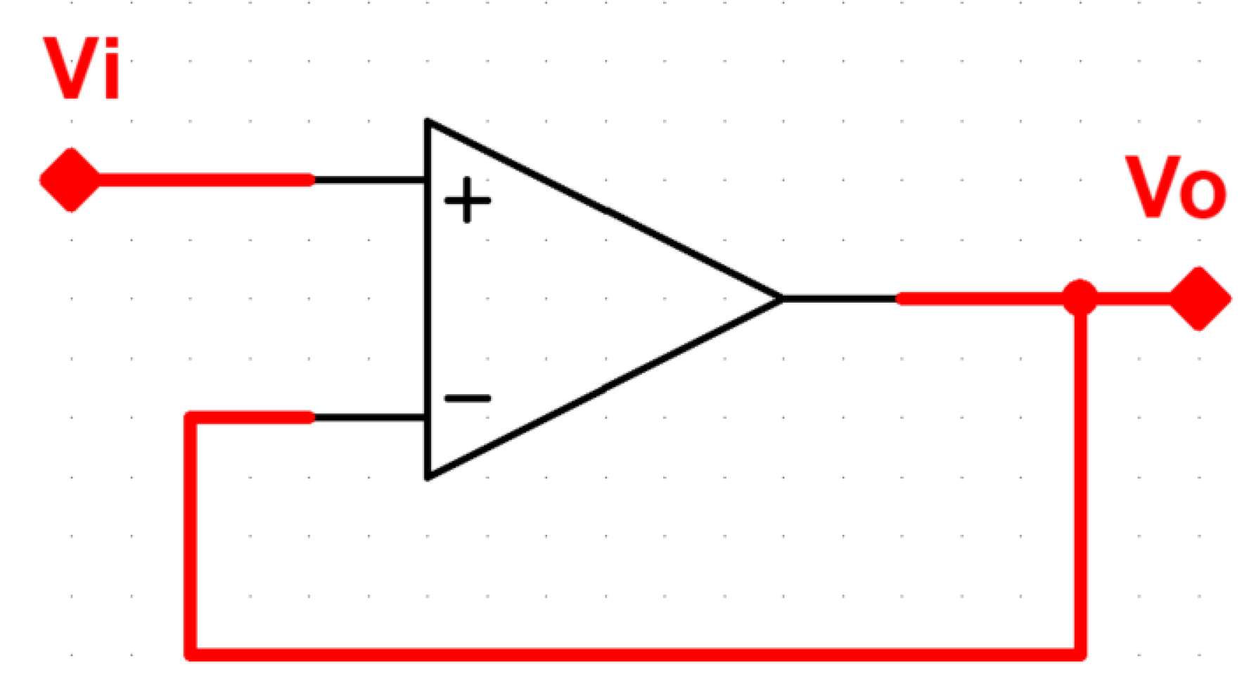
Figure 1. The diagram of voltage follower.
Symmetry 14 02299 g001
Figure 2. The multiplier and resistance-capacity current control by the voltage follower.
Symmetry 14 02299 g002
Figure 3. The multiplier and capacity connected in series.
Symmetry 14 02299 g003
Figure 4. The multiplier and resistance-capacity parallel connection in series.
Symmetry 14 02299 g004
Figure 5. The multiplier and the inverse integration circuit connection in series as isolators.
Symmetry 14 02299 g005
Figure 6. Dynamics of system (4) with a = 10 , c = 40 under IC = [2,2,2]. (a) Lyapunov exponent spectrum. (b) Bifurcation diagram.
Symmetry 14 02299 g006
Figure 7. Symmetry chaotic attractors of system (4) with b = 1 . (a) Numerical simulation. (b) Experimental results.
Symmetry 14 02299 g007
Figure 8. Symmetry chaotic attractors of system (4) with b = 2 . (a) Numerical simulation. (b) Experimental results.
Symmetry 14 02299 g008
Figure 9. Symmetry chaotic attractors of system (4) with b = 3.5 . (a) Numerical simulation. (b) Experimental results.
Symmetry 14 02299 g009
Figure 10. Symmetry chaotic attractors of system (4) with b = 5 . (a) Numerical simulation. (b) Experimental results.
Symmetry 14 02299 g010
Figure 11. Symmetry chaotic attractors of system (4) with b = 6 . (a) Numerical simulation. (b) Experimental results.
Symmetry 14 02299 g011
Figure 12. Dynamics of system (4) with b = 3 , c = 40 under IC = [2,2,2]. (a) Lyapunov exponent spectrum. (b) Bifurcation diagram.
Symmetry 14 02299 g012
Figure 13. Symmetry chaotic attractors of system (4) with a = 3.75 . (a) Numerical simulation. (b) Experimental results.
Symmetry 14 02299 g013
Figure 14. Symmetry chaotic attractors of system (4) with a = 7.5 . (a) Numerical simulation. (b) Experimental results.
Symmetry 14 02299 g014
Figure 15. Symmetry chaotic attractors of system (4) with a = 12 . (a) Numerical simulation. (b) Experimental results.
Symmetry 14 02299 g015
Figure 16. Symmetry chaotic attractors of system (4) with a = 15 . (a) Numerical simulation. (b) Experimental results.
Symmetry 14 02299 g016
Figure 17. The analog circuit of the simplified circuit realization based on voltage follower.
Symmetry 14 02299 g017
Figure 18. The analog circuit of the simplified circuit realization based on inverse integration.
Symmetry 14 02299 g018
Figure 19. The FFT of x variable in system (4). (a) Figure 17 and C 1 = C 2 = C 3 = 100   nF . (b) Figure 17 and C 1 = C 2 = C 3 = 68   nF . (c) Figure 18 and C 1 = C 2 = C 3 = 47   nF . (d) Figure 18 and C 1 = C 2 = C 3 = 22   nF .
Symmetry 14 02299 g019
Figure 20. The phase trajectories of system (9): (a) numerical simulation, (b) circuit simulation.
Symmetry 14 02299 g020
Figure 21. Dynamical evolution of system (9). (a) Average value of the absolute value of the chaotic signal. (b) Lyapunov exponent spectrum.
Symmetry 14 02299 g021
Table 1. Typical phase trajectories of system (4) with a = 10 , c = 40 and initial condition ( 2 , 2 , 2 ) .
b AttractorLyapunov Exponents
1chaotic(0.853348,0,−11.781354)
2chaotic(1.173480,0,−13.136391)
3.5chaotic(1.233097,0,−14.707076)
4chaotic(1.24612,0,−15.218009)
5chaotic(1.252662,0,−16.225784)
6chaotic(1.282429,0,−17.261460)
Table 2. Typical phase trajectories of system (4) with b = 3 , c = 40 and initial condition ( 2 , 2 , 2 ) .
a AttractorLyapunov Exponents
3.75chaotic(0.383651,0,−7.128153)
7.5chaotic(0.935087,0,−11.4205181)
12chaotic(1.294339,0,−16.245770)
15chaotic(1.297606,0,−19.201739)
Publisher’s Note: MDPI stays neutral with regard to jurisdictional claims in published maps and institutional affiliations.