Article

Light and Secure Encryption Technique Based on Artificially Induced Chaos and Nature-Inspired Triggering Method

by
Muhammed J. Al-Muhammed
1,* and
Raed Abu Zitar
2
1
Faculty of Information Technology, American University of Madaba, Madaba 11622, Jordan
2
Sorbonne University Center of Artificial Intelligence, Sorbonne University Abu Dhabi, Abu Dhabi 38044, United Arab Emirates
*
Author to whom correspondence should be addressed.
Symmetry 2022, 14(2), 218; https://doi.org/10.3390/sym14020218
Submission received: 25 December 2021 / Revised: 18 January 2022 / Accepted: 19 January 2022 / Published: 23 January 2022

Abstract

:
Encryption is the de facto method for protecting information, whether this information is locally stored or on transit. Although we have many encryption techniques, they have problems inherited from the computational models that they use. For instance, the standard encryption technique suffers from the substitution box syndrome—the substitution box does not provide enough confusion. This paper proffers a novel encryption method that is both highly secure and lightweight. The proposed technique performs an initial preprocessing on its input plaintext, using fuzzy substitutions and noising techniques to eliminate relationships to the input plaintext. The initially encrypted plaintext is next concealed in enormously complicated codes that are generated using a chaotic system, whose behavior is controlled by a set of operations and a nature-inspired triggering technique. The effectiveness of the security of the proposed technique is analyzed using rigorous randomness tests and entropy.

1. Introduction

Researchers have effectively responded to the need for protecting information by proposing many encryption techniques [1,2,3,4,5,6,7,8,9,10,11,12]. These techniques can be categorized either by how they process their input (stream or block ciphers) or by the shared information between the communicating parties (symmetric or asymmetric). Symmetric encryption techniques (e.g., [13,14,15,16,17,18]) depend on a secret key that is shared between senders/receivers and used for encryption and decryption. This type is the mostly used one because it ensures faster processing. Asymmetric encryption techniques use two different keys [19,20]. A public key is used for encryption, and a private key (known only to the recipient) is used for decryption.
These encryption techniques process their input using different computational models. Conventional methods use operations, such as substitutions, shifting, permutations, and adding the effect of the key [18]. Chaos-based encryption techniques use chaotic systems to induce enough confusion in the resulting ciphertext [21,22,23,24,25,26]. Numerical encryption techniques process their input using mathematical models [27,28,29,30]. These techniques represent the key as a non-linear, one-dimensional function f ( x ) and encrypt plaintext symbols a i by finding the roots for the equation f ( x ) a i = 0 . DNA-based techniques make use of the sophisticated structures of the DNA sequences of living beings [31,32,33,34]. These techniques first manipulate their input using manipulation operations and then hide the resulting messages within the complicated human genomic DNA. Another interesting paper [35] proposed a novel image encryption scheme based on DNA sequence operations and a spatiotemporal chaos system to encrypt images. Neural network-based encryption techniques were also proposed. Authors of [36] proposed a double image encryption algorithm based on convolutional neural networks and dynamic adaptive diffusion. The technique proposed in [37] uses continuous-variable quantum neural network to induce high confusion and thus, secure the ciphered images. The techniques [38,39] propose a chaos-based pseudo-random sequence generator and a DNA-rules-based chaotic encryption algorithm for image encryption.
All the above techniques are important, as they use powerful computational methods that provide reasonable protection for information. Although they passed important security testing, they still have intrinsic problems and security vulnerabilities because of the way they handle their input (plaintexts and keys). The performance of the chaos-based encryption methods fully depends on the quality of the chaotic systems. If the chaotic system is ill-designed or improperly seeded, the corresponding encryption technique is likely to suffer. The chaos-based techniques either do not link the behavior of the chaotic system to the key, or this link is direct and may leak the identity of the key. Although numerical encryption techniques are based on mathematically sound principles, they suffer from real problems. First, finding a function that can form an acceptable key is not easy. Second, using the numerical solutions for the system of equations incur high processing demands and potentially rounding problems for approximating the roots to the correct integer. Third, the decryption becomes impossible in the case of computation overflow errors that result from finding the roots. The conventional encryption methods have problems as well. The entropy of the ciphertext is not sufficiently high [27]. Furthermore, the substitution box is still a leaking point because it is not quite nonlinear [40,41]. The security of the DNA-based methods is built only partially on the manipulation operations, but mainly on the complexity of the DNA. Since the security of the DNA-based techniques is built on the DNA complexity, this may be a problem, given the increasing power of the machines. The neural network techniques are sound, provided that they are well trained and initialized. Since the performance of the neural network-based techniques highly depends on the quality of the initial data and the robustness of the intermediate calculations—which is not easy to achieve—any errors in the initialization are likely to weaken the output (ciphertext).
This paper offers a novel encryption technique that is secure and demands low execution time. The technique is based on several sound operations that can significantly boost the confusion in the ciphertext and, therefore, addresses the vulnerabilities of the other techniques. First, the initial encryption round processes its input using chaotic symbol encoding, diffusion, and distortion techniques. These operations use chaotic and data-dependent means to induce great confusion in the output. Second, the key echo code generator uses expansion techniques, multistage mapping distortion, and biologically triggered mutation operations to create enormously complicated codes for hiding the ciphertext. Third, the hiding method conceals the initially ciphered symbols in the key echo codes. The hiding method involves highly effective mixing operations that—to the best of our knowledge—are unique to the proposed method (all other methods use simple means, such as XOR and addition operations to mix the key effect). Therefore, the proposed encryption technique offers the following contributions.
  • Combining chaotic systems and nature-inspired triggering techniques to ensure high confusion.
  • Diffusion techniques that are greatly sensitive to the input variation and reflect this variation in a high avalanche effect.
  • Effective ciphertext-key echo code mixing operations that ensure deep hiding of the ciphertext in the key echo codes.
  • Key echo generator that effectively hides the encryption key identity.
We present the contributions of this paper as follows. Section 2 presents two fundamental concepts: the substitution space (Section 2.1) and the chaotic system (Section 2.2). Section 3 presents the encryption technique processes: the initial encryption process (Section 3.1), the key echo generation process (Section 3.2), and the key round (Section 3.3). The decryption process is presented in Section 4. Section 5 presents the security testing. Section 6 provides concluding remarks and directions for future work.

2. Preliminaries

This section presents the substitution space operation and the key-controlled chaotic system.

2.1. Substitution Space: S T

The substitution space S T is a 2 p 2 × 2 p 2 table—p is the number of bits that represent a symbol. The 2 p entries of S T are filled with all possible permutations of the p bits. These permutations are placed in S T as specified by the S-Box of AES [18]. The substitution space is used to substitute input plaintext symbols as follows. For any p-bit input symbol o i , the substitution is performed by splitting the bits of o i into left and right halves, where the left half indexes the substitution space’s rows and the right half indexes its columns. The content of the indexed entry is the substitution for o i .

2.2. Chaotic System

The chaotic system uses a one-dimensional logistic map to generate chaotic signals, each with p bits, where p is determined by the ASCII symbols used (For instance, if the ASCII symbols from 0 to 255 are used in the encryption, then p = 8). The logistic map is a simple but very powerful system that uses one bifurcation parameter r. Equation (1) defines the logistic map, where the bifurcation parameter r can assume any value in the interval (0, 4] and x n can assume any value in the open interval (0, 1). Based on [4,42], if 0 r < 3.57 , the system has a specified attractor value (the value or the set of values that the system settles toward over time), and therefore does not show chaotic behavior. If r [ 3.57 , 4 ] , the system becomes in the state of chaos.
x n + 1 = r · x n ( 1 x n )
When the system is in a chaotic state, very different chaotic sequences are generated by modifying the value of x 0 ( 0 , 1 ) and r within their optimal intervals. The paper provides an effective way to correlate the chaotic states of the chaotic system with the encryption key variations. Algorithm 1 provides the logic for initializing x 0 and r using the key.
Algorithm 1 Initializing the parameters of the chaotic system
  • 1. Process the encryption key using the SHA-512 hashing algorithm.
  • Let a 1 a 2 a n be the processed key.
  • 2. Compute a value of x 0 using the left half n / 2 bytes of the key using x 0 = i = 1 n 2 I N T ( a i ) . B i 1 L . i = 1 n 2 B i 1
  • 3. Compute an initial value r 0 for r using the right half n / 2 bytes of the key using  r 0 = i = n 2 + 1 n I N T ( a i ) . B i n 2 R . i = n 2 + 1 n B i 1
  • 4. Adjust the value of r to the optimal range ([3.57, 4]) using the transformation  r = 3.57 + 0.43 × r 0
Let a 1 a 2 a n be the encryption key. As Algorithm 1 shows, step (1) processes the key using the SHA-512 hashing algorithm before using it. This step is important because the SHA-x algorithm is one-way and sensitive to bit variation, which ensures large changes in the initialization values if the key changes. Step (2) computes an initial value for x 0 , using the left half bytes of the processed encryption key ( a 1 a 2 a n 2 ). Likewise, steps (3) and (4) compute an initial value for r, using the right half bytes of the key ( a n 2 a n 2 + 1 a n ). In steps (2) and (3), I N T ( a i ) is the ASCII (integer) value of the symbol a i , L = max 1 i n 2 {INT ( a i )}, R = max n 2 + 1 i n {INT ( a i )}, and B is the radix of the used symbols. For instance, if the range of symbols is 0…255, B = 256. Observe that the values of x 0 and r 0 are always in the range [0, 1]. Step (4) transforms the intermediate value r 0 to the desired interval for r.
When the parameters of chaotic map are initialized (Algorithm 1), the random number generator can produce random numbers by simulating Equation (1). Since the generated random values are within the range [0…1], these numbers can be transformed to the desired interval [0… 2 p ] using Equation (2)—where x i [ 0 , 1 ) is generated by Formula (1).
z i = M O D ( x i × 10 14 , 2 p )

3. The Encryption Technique

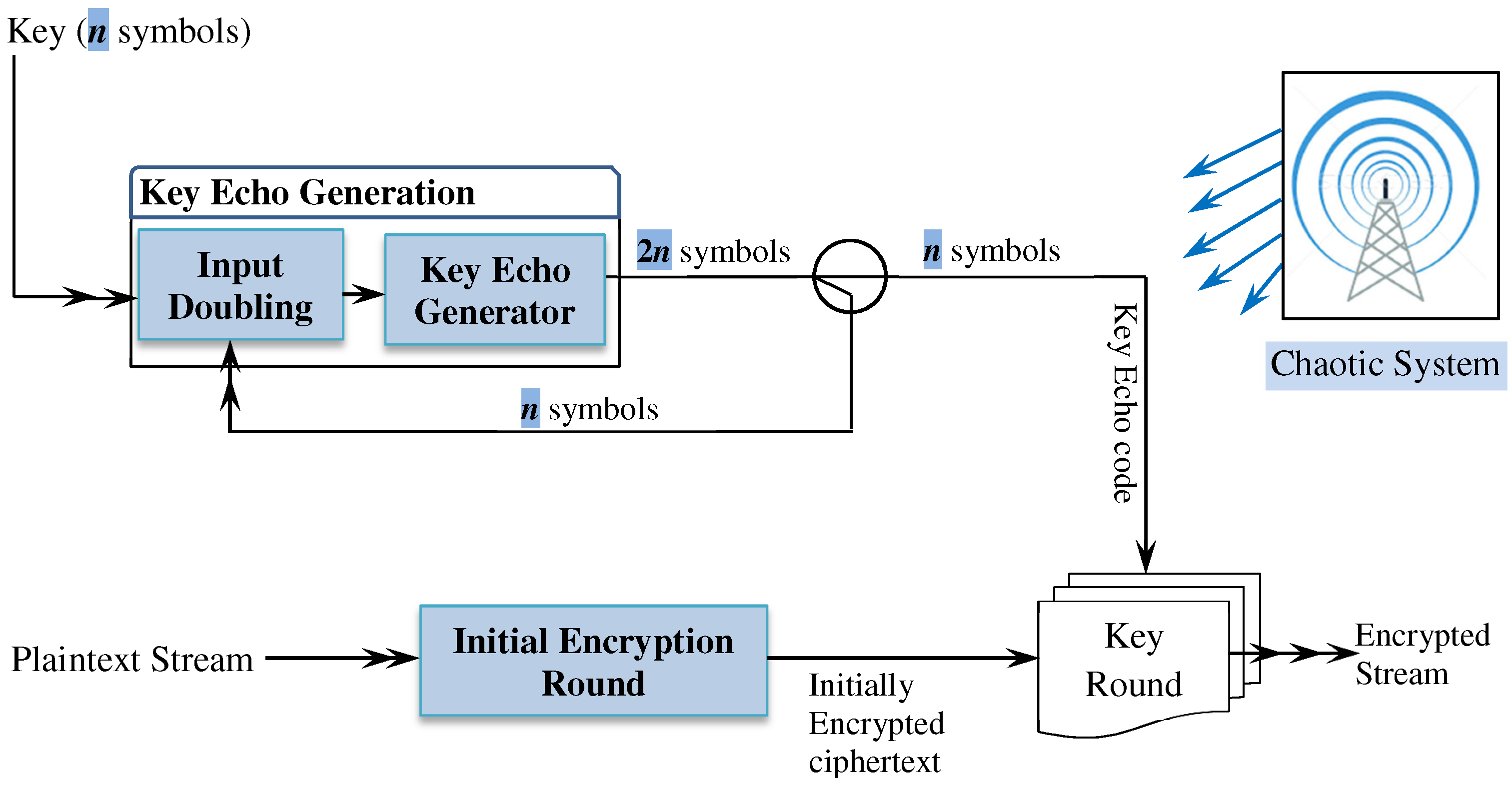
Figure 1 shows the core components of the proposed encryption technique. The technique processes plaintext using two rounds. The initial encryption round processes plaintext and outputs an initially encrypted text. All the processing involved in this round is independent of the encryption key. The key echo generation processes the encryption key and generates key echo codes. The key round uses complex and non-linear operators to add enormously complicated key codes to the initial ciphertext. The chaotic system provides chaotic signals for supporting the encryption process.

3.1. Initial Encryption Round

The initial encryption is a key-independent operation. It uses three fundamental operations to process its input (see Figure 2). The diffuser operation increases the avalanche effect of the output by detecting plaintext variations and propagating these variations to impact every other symbol. The encoder operation transforms the input symbols to new symbols using the symbol itself and other noise values that add fuzzy impact to the functionality of the encoding process. The distorter operation adopts a fuzzy model to invoke distortion operations for handling input symbols.
Before presenting the technical details of each operation, we introduce a piece of knowledge—the control variable—that supports the functionality of the encryption round operations.

3.1.1. The Control Variable

The control variable is a sequence of p k bits. The value p is the maximum number of bits required for representing the used symbols (e.g., p = 8 if the used symbols are integers within the range 0…255) and k is the total number of p-bit subsequences required for supporting the functionality of the initial encryption operations. The process of initializing and updating the control variable X n is illustrated in Figure 3. The process consists of initializing the control variable X n and an update process called the update loop. The control variable X n is initialized with k chaotic values H i (p bits each) by an XOR operation and left shifting by “( i 1 )*p” positions.
The update loop consists of the updater and the pollinator operations and is repeatedly invoked every time the initial encryption round processes an input symbol. When invoked, the updater manipulates the control variable X n using three steps (iiii), which are the steps used in the XorShift random generator. In addition, the updater maintains three variables q i ( i = 1 , 2 , 3 ) that support the functionality of the pollinator. The updater refreshes the values of q i by adding three values y i extracted from the control variable. The rightmost 9 bits of the control variable are used to form y i as follows: y 1 is the decimal value of the rightmost three bits, y 2 is the decimal value of the next three bits, and y 3 is the decimal value of the last three bits.
The pollinator updates the control variable by including the impact of the input symbols in it (the control variable). Unlike the updater, which is repeatedly invoked, the pollinator is invoked using a logic that is based on the input symbols. To implement this invocation logic, the pollinator maintains three layers of data, where each layer has 2 p entries (see Figure 3). Layer L 1 (the innermost circle) is populated by replicating 8 direction flags that determine the 8 possible move directions starting from a cell in the substitution space S T (We call the cell that we start the move from a reference cell). These flags are either unidirectional or bidirectional. The unidirectional flags allow the move to be along the row or the column of the reference point. We define four unidirectional flags: two flags allow the move along the row either to the left (L) or to the right (R) of the reference point, and two flags allow the move along the column either to the top (T) or to the bottom (B) of the reference point. The bidirectional flags allow the move to be along the four diagonals of the reference point. We define four bidirectional flags: two flags allow the move along the top right diagonal (TRC) or the top left diagonal (TLC), and two flags allow the move to the bottom right diagonal (BRC) or the bottom left diagonal (BLC). L 2 is populated with the integers 0 2 p 1 . The entries of L 2 determine the amount of the move (within the substitution space) starting from the reference cell. The outer layer L 3 contains equal replications of two values “U” (execute pollinator) and “N” (do not execute). The 2 p entries of each layer L i ( i = 1 , 2 , 3 ) are randomly shuffled using a sequence of 2 p chaotic numbers obtained from the chaotic system.
Accordingly, the update loop refreshes the value of the control variable as follows. The pollinator checks the possibility of including the impact of the input symbol a i (assuming the currently considered symbol is a i + 1 ) by accessing L 3 . The access takes the general format: L k [ q k + a i ], where a i is a plaintext symbol and q k is one of the variables maintained by the updater. If the outcome of the access is “U” (i.e., L 3 [ q 3 + a i ] = “U”) the pollinator is triggered and updates the control variable using the values L 1 [ q 1 + a i ] and L 2 [ q 2 + a i ]. If the content of L 1 [ q 1 + a i ] is a unidirectional flag (R, L, T, or B), the pollinator moves (starting from the reference point) along the direction flag a number of positions equal to the decimal value of the right p 2 bits of the distance value L 2 [ q 2 + a i ] (The input plaintext a i designates the reference point within the substitution space. The left half bits of a i designate the row of the reference point, and the right half bits of a i designate its columns). If the content of L 1 [ q 1 + a i ] is a bidirectional flag (TRC, TLC, BLC, or BRC), the pollinator moves (starting from the reference point) along the direction flag a number of positions on both the rows and columns of the substitution space. The amount of the move on the rows and the columns equals, respectively, the decimal value of the left p 2 bits and the right p 2 bits of the distance value L 2 [ q 2 + a i ]. In either case, the content of the reached cell, say N i , is used to pollinate the control variable. The pollinator determines the bits of the control variable that should be pollinated using the variable z, where z is the decimal value of the right three bits of the input plaintext a i . The actual pollination is achieved (see Figure 3) by left-shifting N i a number of positions equal to “ p z ” and XOR’ing the outcome with the control variable X n .
We use a simple example to demonstrate the move within the substitution space starting from a reference point. Suppose that the direction flag is the unidirectional T and the amount of the move is 151 “1001 0111”. Based on this configuration, the pollinator moves 7 cells (the value of the right half bits of 151) up the reference cell designated by a i (wrap if necessary) and retrieves the value N i . Suppose now that the direction flag is T R C and the amount of the move is 28 “0001 1100”. Based on this configuration, the pollinator moves 1 row (the value of the left half bits) and 12 columns (the value of the right half bits) along the top right diagonal (wrap is necessary). The content of the reached cell is the value N i .
The initial encryption process needs 8 P bits to support its operations. Therefore, the control variable length is 8p bits (i.e., k = 8). These bits are consumed by the initial encryption process operations as specified by Figure 4. As Figure 4 shows, the rightmost p bits are used to support the functionality of the encoder. The left 7p bits are used as follows: the rightmost of the 3p bits are used for triggering the distortion process, the next p bits (toward the left) are used for selecting a specific distortion operation, the next p bits are used as a flipping pattern, and the leftmost 2p bits are used for reordering the distortion operations list.

3.1.2. Encoder Operation

The encryption technique uses a sliding-point encoder to encode plaintext input symbols a 1 a 2 a n . To encode an input symbol a i ’, the encoder creates a sliding point ( s 1 , s 2 ) using the rightmost p bits of the control variable, where s 1 and s 2 are, respectively, the decimal values of the left/right p/2 bits. It also creates a reference point ( r 1 , r 2 ) within the substitution space by splitting the bits of the input symbol a i , where r 1 and r 2 are, respectively, the left/right half bits of a i . The encoder uses ( s 1 , s 2 ) to slide from the reference point ( r 1 , r 2 ) to a new point within the substitution space. The sliding is a non-linear transformation, which is performed by left-shift “ ” and X O R “⊕” ( s 1 1 r 1 , s 2 1 r 2 ). The encoder uses the content of the accessed cell as the code for the input symbol a i .
The encoder operation has the following decoder that restores the original symbols. Let ( s 1 , s 2 ) be the sliding point that was used to encode the input symbol a i , and ( c 1 , c 2 ) is the cell from which the code of a i was retrieved. The following two steps restore the original symbol: r 1 = ( s 1 1 ) c 1 M o d | c 1 | and r 2 = ( s 2 1 ) c 2 M o d | c 2 | , where M o d is the division remainder and | w | is the number of w’s bits. The decimal value of the concatenation of, respectively, the bits of r 1 and r 2 is the original symbol a i .

3.1.3. Distortion Operation

The distortion operation sharply manipulates the bits of the input symbols using the operations defined in Table 1. Chaotic-Mutate (y, v) mutates bits of the input symbol y by XOR’ing it with the chaotic value v. The chaotic value v is computed by XOR’ing a chaotic value θ (obtained from the chaotic system) and the p bits of the control variable dedicated for chaotic mutation operation (see Figure 4). Shift-Left (y, s) circularly left shifts the bits of the input y by s positions (s = 1… p 1 ). LRHi-Flip (y, f) interleaves the left half bits of the input symbol y between the right half bits (either in the even or odd positions) based on the argument f. The argument f has eight possible states described in the table. These operations are initially ordered in a list as follows: Shift-Left (y, 1), …, Shift-Left (y, p 1 ), LRHi-Flip (y, 0), LRHi-Flip (y, 1), …, LRHi-Flip (y, 7), Chaotic-Mutate (y, v). The order, however, changes as we describe next.
The distortion operation is stochastically triggered. Let U be the integer value of the 3 p bits of the control variable dedicated for the distortion process, and V be the maximum number that can be created from 3 p bits (when all bits are ones). The ratio A = U V is a value in [0, 1]. The distortion process is triggered if A > q , where 0 q 1 . The threshold q determines the intensity of the stochastic triggering. For instance, no distortion occurs when q = 1, while statistically 75% of the symbols are distorted when q = 0.25. When the distortion process is triggered, it selects a distortion operation using the p bits of the control variable (dedicated for selecting a distortion operation) and uses the chosen operation to distort the input symbol (The selection of a distortion operation is achieved by simple model, such as Mod (D, L), where D is the decimal value of the p bits of the control variable, L is the length of the distortion operations list, and Mod is the division remainder).
After processing an input symbol, the distortion process updates the order of the operations list using the designated 2p bits of the control variable. The left p bits are used to circularly left shift the content of the list and the right p bits are used to swap the operation at the index created from the p bits with the operation at the index zero.
The distortion operation has the following distortion operation inverse. The impact of the operation Chaotic-Mutate (y, v) is straightforwardly reversed by regenerating the same chaotic value v and XOR’ing it with the input symbol y. The impact of the left shift operation Shift-Left (y, s) is easily reversed by right shifting the symbol s positions. Finally, the impact of the operation LRHi-Flip (y, f) is reversed by collecting the bits from either odd or even positions depending on f, handling these bits (if needed), and appending them as a prefix for the remaining bits.

3.1.4. Diffuser Operation

A secure encryption technique must have a high avalanche effect [43]. The computational model uses a lookback technique to detect the variations in the previously processed input symbols and propagate these variations to impact all the subsequent symbols. Figure 5 defines the algorithmic steps for embedding the effect of the previous symbols a 1 a 2 a i 1 in the outcome of processing the current a i . The XOR+Shift operation accumulates the effect of the previously processed symbols ( a 1 a 2 a i 1 ) as follows. The input to the XOR+Shift operation is the values X and L. The value X receives the input symbol a i 1 when the diffuser considers the symbols a i ( i > 1 ) (The value X is zero when the diffuser considers the first input symbol a 1 ). The value L is initially zero. The output of the XOR+Shift operation is the value B. The decimal value of the rightmost p bits of B is used as a diffusion value R, which is XOR’ed with the current input symbol. The decimal value of the remaining bits of B are assigned to L, which serves as a “memory” that accumulates the impact of the previously processed symbols. It is worth noting that by splitting B, the manipulation of the current input a i is independent of the manipulation of the next input symbol a i + 1 .
The diffuser operation has the following diffuser operation inverse that restores the original symbols. The symbol a 1 is obtained from d 1 by XOR’ing d 1 with R, where R is computed from the initial values of L and X (zeros). Once a i 1 is restored from d i 1 , the diffuser inverse restores the symbol a i from d i using the previously restored original symbol a i 1 as a value for X and the new value of L.
3.2. Key Echo Generation

The key echo generation is a process for producing arbitrarily long sequences of codes created using the encryption key [44]. These codes must be enormously complicated to hide the encryption key and provide an impenetrable shield to conceal the ciphertext symbols. The paper proposes a key echo generation process that creates very effective code sequences. This process uses two operations: input-doubling operation that expands its n-symbol input to 2n-symbol output and key-echo generator that deeply processes the output of the input doubling operation and produces random code sequences.

3.2.1. Input-Doubling Operation

The input-doubling operation receives sequences of n symbols and outputs sequences of 2n symbols. Initially, the n-symbol input ( x 1 x 2 x n ) is the encryption key. The input-doubling operation expands the n-symbol input using four actions outlined in Figure 6. The right n symbols of the output are fed back as an input for producing more 2n-symbol sequences, while the left n bits are passed to the key echo generator (the key echo generator is discussed next).

The Mutation and Augmentation Actions

The mutation action makes micro changes to the bits of its input symbols. Its functionality can be described by the following sequence of invocations (see Figure 6): (1) invoke the bit-mixing action to process the input x 1 x 2 x n and produce the output y 1 y 2 y n , (2) substitute the resulting sequence y 1 y 2 y n to produce a new sequence m 1 m 2 m n , and (3) perform an XOR operation between each original symbol x i and the processed symbol m i to yield s 1 s 2 s n . The augmentation action does essentially the same steps as the mutation action, except that the outcome of the substitution a i is appended as a suffix to the input s 1 s 2 s n .

Deep Bit-Mixing Action

The deep bit-mixing action detects any variation in the input and compiles these variations to substantial changes to the output. To maximize the sensitivity to the input variations, the action uses dual-pass processing: forward mixing and backward mixing (see Figure 7). The forward mixing processes the first input symbol b 1 by substituting it and producing the new symbol c 1 . For all input symbols b i ( i > 1 ), the input symbol b i is first XOR’ed (⊕) with the most recent output symbol c i 1 and the outcome of the XOR operation is then substituted.
The backward mixing handles the output of the forward mixing ( c 1 c 2 c n ) using similar processing logic, but it starts processing the input backward—right to left. Due to the dual-pass bit mixing, the bit-mixing action is highly sensitive to the input variations—regardless of the scale of the variation (a single bit or more) and its position within the input. Furthermore, for effective bit mixing, the deep bit-mixing action handles the input in W rounds.

Permutation Action

The permutation impacts the order of the input sequence rather than its individual symbols. It uses a data-dependent algorithm along with data-dependent distortions to reorder the input x 0 x 1 x n 1 . Algorithm 2 shows the logic of the permutation action. The action maintains a state variable L I P (initially zero) to remember the index of the last insertion point and generates data-dependent distortion. The algorithm computes the location k for x i + 1 using the input symbol x i and the distortion variable LIP and then moves x i + 1 to the new location k (within the input sequence). Referring to Algorithm 2, if x i < L I P , the action moves x i + 1 to the position k = L b i t s ( x i LIP), where L b i t s is an operator that selects a number of bits from the leftmost of its argument sufficient to index any symbol in the output (For instance, if the input is 16 symbols, this operator selects the leftmost 4 bits since 4 bits are adequate to index any of the 16 symbols). If LIP x i , the action moves x i + 1 to the position k = R b i t s ( x i LIP), where R b i t s is the same as L b i t s , except it selects the bits from the rightmost.
Algorithm 2 Data-dependent permutation action
  • PERMUTE ( x 0 x 1 x n 1 )
  • LIP = 0
  • Fori = 0 to n−2 Do
  •    a. move x i + 1 to a new position k as follows
  •       If  L I P < x i move x i + 1 to the position k = L b i t s ( x i  LIP)
  •       Else move x i + 1 to the position k = R b i t s ( x i  LIP)
  •    b. Update LIP = k
The functionality of the input doubling operation can be described as follows. The mutation action handles the input x 1 x 2 x n . The augmentation action doubles its n-symbol input to produce 2n-symbol output. The permutation action reorders the output of the augmentation action (2n symbols). Finally, the right n symbols are fed back to the input doubling action for producing further 2n-symbol sequences, and the left n symbols are passed to the key echo generator (discussed next) to produce key echo sequences.

3.2.2. Flirt-Mate Triggering Technique

The technique generates two control signals (signal1 and signal2) to adjust its own functionality and the functionality of the key-echo generator (discussed next). Figure 8 shows the components of this technique. The technique is composed of a single n-gene chromosome Y and an internal mechanism for controlling the chromosome evolution. When a variable X flirts with the chromosome Y, the technique checks if the flirting variable is eligible to mate with the chromosome. The mate eligibility is defined by the genetic diversity adequacy, which is measured by the number of genes that differs in the corresponding positions of X and Y (We call the number of different genes, the degree of fitness, or df). If the degree of fitness exceeds the threshold n/2, X and Y are eligible to mate (effective flirt) and both signals 1 and 2 contain the value “effective”. If the mate eligibility condition does not hold, both signals 1 and 2 contain the value “ineffective” (ineffective flirt).
When the chromosome evolution action receives the signal2, it updates the chromosome Y using the operators in Table 2. The operator Flip() updates the chromosome Y by XOR’ing it with the flirting variable X and possibly with a noise value f. The noise value f (initially zero) is updated whether the Flip() operator is invoked or not, using the formula f=Substitute ( f 2 ⊕df), where Substitute(.) substitutes its argument using the substitution space S T . The operator Crossover (m, flag) replaces m genes of the chromosome Y with m genes of the flirting variable X. The positions of the genes are determined by the flag, which could assume any of the four directives: LL (Left-Left), RR (Right-Right), LR, and RL (The directive LL means that the left m bits of Y are replaced with the left m bits of X and RR means the right m bits of Y are replaced with the right m bits of X. The semantics of RL and LR follows). The values for the flag and m are assigned according to Algorithm 3. The value f is split into two halves A and B. Based on A and B, the procedure produces one of the four directives. The value of m is computed as a module (division remainder) of f and n (m is the number of bits). Which of the two update operators to invoke depends on the value of signal2: if the value is “effective”, invoke Crossover() operator, else invoke Flip(). Observe, we try here to capture the intuitive meaning of the mate: if the mate happens, the two variables (flirting variable X and the chromosome Y) exchange genes; otherwise, we only change the bits of the chromosome Y.
Algorithm 3 Assigning values for the flag and m
  • Let A and B be, respectively, the decimal values of the left n/2 bits and the right n/2 bits of f.
  • If A < 2 n 2 , then f l a g = LElse f l a g = R   ▹assign a value to flag
  • If B 2 n 2 , then f l a g · = LElse f l a g · = R   ▹concatenate (·) a second value toflag
  • m = f Mod n

3.2.3. Key Echo Generator

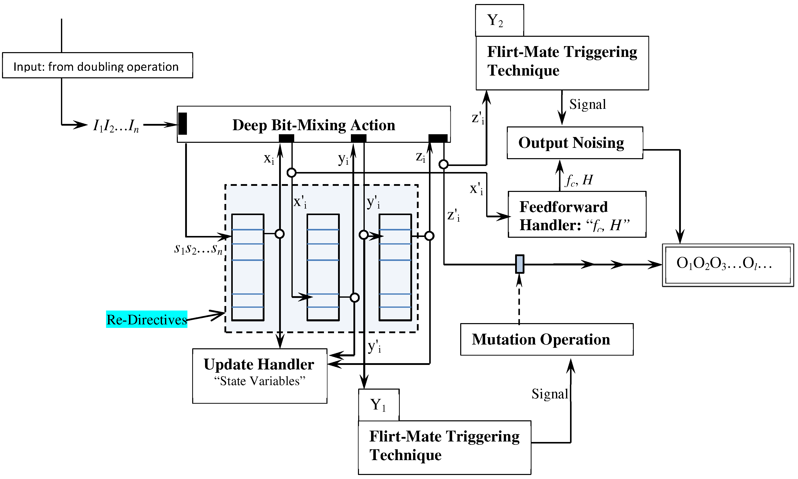
The key echo generator is a three-stage process that further manipulates the output of the input doubling operation. Figure 9 shows the three stages of the echo generator. The first stage consists of Deep Bit-Mixing Action and Re-Directives operations. The second stage consists of the Mutation operation, which makes fine-grained modifications to some of its input symbols. The third stage consists of the Output Noising operation, which further randomizes the output sequence by reordering the symbols of the output. As Figure 9 shows, we have two instances of the flirt-mate triggering technique, each with its own different chromosome. The two chromosomes Y 1 and Y 2 are initialized with values obtained from the chaotic system.
The input I 1 I 2 I n is first processed by the bit-mixing action. This initial processing is very important for boosting the avalanche effect [43,45]). The Re-Directives is a T-layer distortion operation. Each layer L i contains the integers 0… 2 p 1 , where p is the maximum number of bits that represent a symbol. The entries of each layer are independently shuffled using a sequence of numbers r i (i = 1, 2, …,2 p ) obtained from the chaotic system, where the integer at index k is swapped with the integer at the index r k . The input to the first layer is a symbol s i , and the output is a symbol x i indexed by s i . The output of the layer L i 1 is first manipulated by the bit-mixing action and then passed as an input for the next layer L i .
The flirt-mate technique triggers the mutation operation by passing an activation signal that carries the state of the flirtation between the symbol y i ’ (the output of the layer L T 1 ) and the chromosome Y 1 . If the signal carries the value “effective”, the mutation operation intercepts the symbol z i ’ (the output of the last layer L T ), XOR’es it with the pattern U, and appends it to the output list. The pattern U is a symbol with p bits (initially zero) but is updated using the two instructions in (3) regardless of whether the mutation operation is performed flipping or not (i.e., whether the signal carries “effective” or “ineffective” state). Instruction 1 unconditionally updates the pattern U by left shifting U for two positions and then XOR’ing the outcome with the degree of fitness (df). Instruction 2 is executed only if the activation signal carries an “ineffective” state. This instruction further updates U by left shifting U for four positions and XOR’ing the outcome of the shift with z i (the output of the last mapping layer).
1 . U = ( U 2 ) d f t h i s c o m p u t a t i o n i s a l w a y s p e r f o r m e d 2 . U = ( U 4 ) z i e x e c u t e s o n l y w h e n f l i r t i n g i s i n e f f e c t i v e
The output noising operation (the third stage) induces further confusion to the output sequence by reordering the output symbols. It uses the operations Feedforward Handler and Flirt-Mate technique to support its functionality. The Feedforward Handler computes two values H and f c using the logic in Algorithm 4. The feedforward handler uses the symbol x i (the output of the first layer after diffusion has taken place) and calculates f c using simple bit operations (bit shift “ > > or < < ” and XOR “⊕") and the substitution operation. The variable H is computed by H = ( H f k ) / 2 p (k = 1, 2… c 1 ).
The Flirt-Mate technique sends activation signals to the output noising operation. If the received activation signal is “effective", the output noising reorders the output by executing the two operators described in Table 3. The Permute (h) operator is executed first then Shift (k) is executed next. The Permute (h) performs h swaps, where h is the degree of fitness. Each swap exchanges the element at index i (i = 0, 1…h − 1) with the symbol at index j, which is computed using j = f c x i 2 p L o u t ± H x i . The symbol f c is the most recent feedforward symbol; p is the number of bits that represents a symbol; x i is the unicode value of the symbol at location i; L o u t is the length of the current output list; and H is the accumulated history of the previous feedforward symbols. The offset H x i is added (+) or subtracted (–) if x i is, respectively, even or odd. Shift (k) operator moves the symbols of the output list by k positions to the left. The number of positions k is equal to H x i after adding the effect of the most recent feedforward symbol to H (Observe that the new index j depends on both the current feedforward symbol f c and the accumulated history of all the previous feedforwards f 1 f 2 f c 1 . This data-dependent computation makes the selection of each index j involve plenty of fuzziness. Furthermore, the shift operator maximizes the effectiveness of the Permute(h) operator by changing the symbols that will be influenced by every permutation).
Algorithm 4 Computing the feedforward symbol f c
  • Forward-Handler ( x i )
  • v i = Substitute ( x i )             ***Substitute  x i using S T
  • w i = v i ( v i < < 2 )           ***Left shift  v i and XOR the result with  v i
  • w ¨ i = w i ( 2 > > w i )       ***Right shift  w i  and XOR the result with  w i
  • f c = Substitute ( w ¨ i )            ***Compute  f c  by substituting  w ¨ i
  • Return  f c
The update handler maintains a state variable V L i for each layer L i . The state variables are initialized to 0, but updated after processing each input symbol. The update handler updates each state variable V L i by XOR’ing its current value with the output of the respective layer L i just before passing this output to the bit-mixing action. These state variables are used to update the order of the elements in the re-directive layers L i .
After discussing the processing stages and the update handler, we describe how the key echo generator processes its input I 1 I 2 I n and creates the key echo codes. Firstly, the bit-mixing action processes the input sequence and yields the new sequence s 1 s 2 s n . The re-directives distort each symbol s i through mapping it to the layers’ L i . The output symbol of each layer L i is used to update the state variable V L i and is also passed to the bit-mixing action for further distortion before mapping it to the next layer L i + 1 . Secondly, the output of the last layer ( L T ) may receive additional distortion based on the activation signal sent by the flirt-mate triggering technique. If the activation signal carries the value “effective” (an effective flirt state), the mutation operation distorts the symbol by XOR’ing it with the pattern U. Thirdly, the  output sequence may receive reordering for some of its symbols if the corresponding flirt-mate triggering technique instructs the output noising operation. Before processing additional sequences I 1 I 2 I n from the input doubling operation, the state of re-directive layers are slightly modified by partially reordering their elements. Namely, the entries of each layer L i are left shifted by i positions and the content of the first cell L i [0] is swapped with the content of the cell L i [ V L i ] .

3.3. The Key Round

The key round embeds the effect of the key echo codes in the initially encrypted plaintext. Unlike other encryption methods that add the key effect using a single operation, the proposed technique defines different operations to embed the effect of the key (Table 4). The operator XOR(s, k) performs an XOR operation between the input symbol s and the key echo symbol k. The operator L R X [ m ] (s, k) left rotates the input symbol s by m positions and then XOR’es the outcome with the key echo symbol k. (m = 1, 2, …, p 1 , where p is the number of bits that represent a symbol). The operator T X [i, l, j, Q](s, k) breaks the structure of the input symbol s by extracting a selected subsequence of its bits and appending it as a prefix or a suffix to the remaining bits (of the original symbol). The operator extracts l bits starting from i. It may further process the selected subsequence based on the directives defined in Q. In particular, the operator flips the bits of the selected sequence if the directive is “Flip”; reverses the order of the bits of the sequence if the directive is “Reverse”; or leaves the subsequence unprocessed if the directive is “NoOp”. Once the subsequence is processed, the operator appends the subsequence to the remaining bits as a suffix or a prefix based on the value of j, where j {Suffix, Prefix}. Finally, the processed symbol is XOR’ed with the key echo symbol k. Figure 10 shows an example of the T X functionality.
Each of the mixing operators in Table 4 has an inverse operator. The operator L R X [ m ] (s, k) impact is reversed by first XOR’ing the input symbol with the key echo symbol k and then right rotate the outcome of the XOR by m positions. The operator XOR (s, k) impact is reversed by XOR’ing the input symbol with k. Reversing the impact of the operator T X [i, l, j, Q](s, k) is a bit complicated and performed by the steps described in Algorithm 5.
Algorithm 5 Inverse of T X mixing operator
  • Let c i be the input symbol. T X [i,l,j,Q](s,k) performs the following steps to obtain the original symbol s
  •    (1)  d i = c i k i
  •    (2) Extract the leftmost or the rightmost l symbols from  d i  based on the value of j.
  •    (3) Handle the extracted bits based on the value of Q.
  •    (4) Place the extracted bits at the position iof the d i
Figure 11 outlines the logic of the key round. The mixing module executes the selected operator to produce the final ciphertext symbol v i . The indexing mechanism produces an index I to access one of the entries of the mixing operators list. The production of the index I is both data-dependent because it uses the input symbol c i 1 and is chaotic due to the use of the well-known chaotic system called rotation–transformation. This system is defined by Equation (4) ([46], p. 191).
x k + 1 = a + b . ( x k c o s ( θ k ) y k s i n ( θ k ) ) y k + 1 = b . ( x k s i n ( θ k ) + y k c o s ( θ k ) ) θ k = c + d ( x k 2 + y k 2 )
The parameters of the rotation–transformation system are better set as follows [46]: a = 6 , b = 0.8 , c = a / 2 , d = a . The initial values for x 0 and y 0 can respectively be assigned from their effective ranges (0, 1) and (−1, 1). In the proposed approach, the values for x 0 and y 0 are randomly selected from the effective ranges using the chaotic system. The index I is computed by Equation (5). We take the Mod (division remainder) of 2 p because all the symbols are represented by p bits. In addition, we include the effect of the input data by XOR’ing the initial index value with the c i 1 (the previous input symbol).
I = M o d [ f l o o r ( x k + 1 × y k + 1 × 10 14 ) , 2 p ] c i 1

4. The Decryption Process

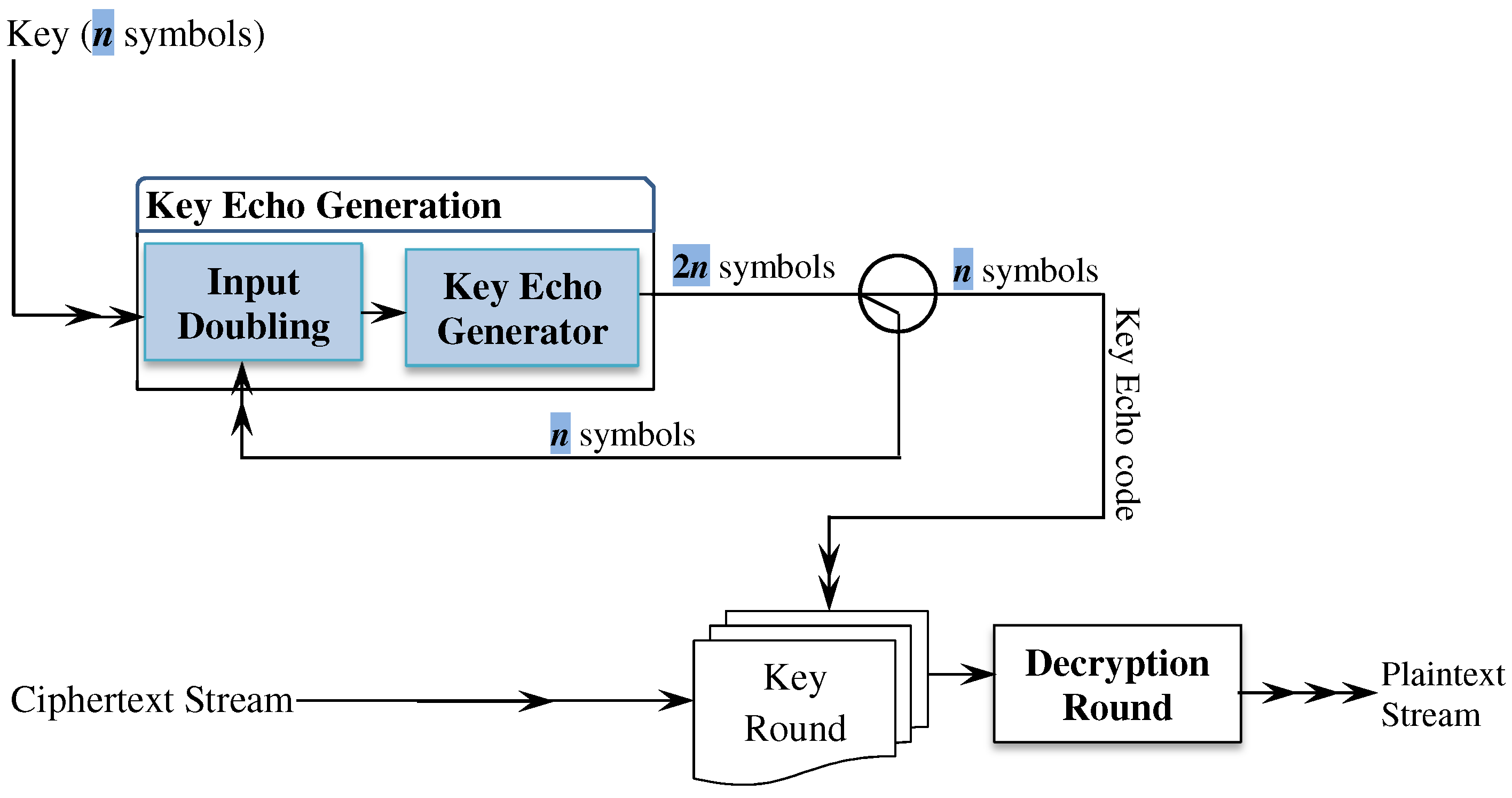
The decryption operation is outlined in Figure 12. The decryption process first handles the ciphertext using the key echo round (Section 3.3) to remove the impact of the key. In the decryption process, the key round must use the mixing operations inverse rather than the mixing operations per se. There is no change to the key-echo generation process or to creating/updating the control variable.
The output of the key round is the initial ciphertext that is produced by the initial encryption round. To successfully decipher the initial ciphertext, the decryption round executes the same processing flow of the initial encryption in Figure 2 but backward (from distortion process back to diffuser process) and the inverse operation for each encryption operation is used (The inverse of each encryption operation is described in the context of the description of each encryption operation). For instance, to restore the plaintext processed by the distortion process, the decryption round uses the distortion process inverse (Section 3.1.3) and to restore the plaintext processed by the sliding-point encoder, the decryption process uses the decoder process (Section 3.1.2).

5. Security Analysis

We evaluate the proposed technique in this section. The evaluation includes (1) the key echo code generation (Section 5.1) and (2) the encryption technique (Section 5.2). We also discuss why the proposed technique resists the classical security attacks (Section 5.3) and estimated the time complexity for the proposed technique (Section 5.4). The performance analysis was done using the NIST (National Institute for Science and Technology) battery of randomness tests [47], ENT battery of randomness tests [48], entropy, and avalanche effect.

5.1. Key Echo Code Generator

The test case consists of a large set of 128-bit keys (5000 keys). For a good key diversity, the keys were obtained using different methods. We obtained 2500 random keys generated using online service (passwordsgenerator.net) and handcrafted 100 keys. The other 2400 keys were low entropy keys and obtained by flipping bits of a 128-bit key of all zeros. In particular, 128 keys were obtained by flipping only the ith bit (i = 1…128). The remaining low entropy keys (2372) were obtained by flipping l bits at random positions (l = 2, 3, 4, 5…64) (Observe, we intentionally flipped only up to half of the input key bits to preserve low entropy property in the resulting keys).

5.1.1. Entropy

The key echo code generator used the 5000 keys to produce 5000-long code sequences, where each sequence is 128,000 symbols (1,024,000 bits). Since the performance of the deep-bit mixing depends on the number of rounds it executes and the performance of the re-directives layer depends on the number of mapping layers, we analyzed the impact of rounds and the mapping layers on the overall performance of the key code generator. The key echo code generator was executed several times for different values of the rounds and the re-directives layers. Figure 13 shows the average entropy over all the sequences. As the figure shows, the entropy improves (getting closer to the ideal value 1) as the number of rounds and the number of layers increase. This improvement is significant up to 4 rounds (for the deep-bit mix) and 4 layers (for the re-directives). It is clear also that there is no remarkable improvement in the values of the entropy beyond 4 rounds and 4 layers.

5.1.2. Avalanche Effect

To effectively examine the avalanche effect of the key echo code generator, we used a low entropy 128-bit key of all zeros. We then constructed different perturbed keys from the low entropy key by flipping bits at random positions (We used the computer built-in random generator for choosing the random positions). Because there is a huge number of possibilities, we flipped only i bits (i = 1, 2, 3, 4, 8, 12, 16, 24, 32, 64, and 96) to create the perturbed keys. We constructed 30 different perturbed keys for each i flipped bits. For instance, we constructed different 30 perturbed keys, where each perturbed key was created by flipping the input key (all bits are zeros) in a single random position. The key echo generator created a code sequence of 1024 symbols (8192 bits) for every used key. When the key echo generator produces the sequence, it uses a different number of re-directive layers and executed the deep-bit mixing operation for a different number of rounds. As in [49], the avalanche effect is determined by computing the Hamming distance between the sequences generated using the input key (bits are all zeros) and the sequences generated using its corresponding perturbed keys (The Hamming distance is the number of bits that differ at the identical locations of two equal-size sequences).
Figure 14 shows the average Hamming distance (avalanche effect) as a function of the number of re-directive layers and the number of deep-bit mixing rounds. As the figure shows, the avalanche effect increases as the number of rounds and layers increases. When the deep-bit mixing operation executes only one round, the avalanche effect is not satisfactory regardless of the number of re-directive layers. That is because the Hamming distance between the two sequences generated from the input key and its perturbed key is less than half of the sequences bits (8192 bits) (As in [49], in order for the avalanche effect to be effective, more than half of the bits must change when a bit or more change). Obviously as the number of rounds increases, the avalanche effect increases. It could be inferred from the figure that 4 rounds and 4 re-directive layers give a high avalanche effect (more that 5000 bits changed). In addition, executing the deep-bit mixing operation for more than 4 rounds does not significantly improve the avalanche effect regardless of the number of layers of the re-directives (We call the configuration of 4 rounds and 4 layers, the effective configuration of the key echo generator).
Figure 15 shows the Hamming distance as a function of the number of flipped bits. The figure depicts the Hamming distance for sequences generated using 4 rounds of the deep-bit mixing operation and 4 layers of re-directives. As the figure shows, the minimum average Hamming distance (avalanche effect) exceeds 5000 bits difference, regardless of the number of flipped bits. The confidence intervals around the average—represented by the error bars—show that there is no significant difference in the average of Hamming distance when the number of the flipped bits changes (observe that the intervals overlap). As such, the avalanche effect of the key echo code generator is high and it is independent of the number of flipped bits.

5.1.3. ENT: Randomness Test

To further investigate the performance of the key echo code generator, we tested the randomness of the sequences. Namely, we tested the sequences that were generated—in Section 5.1.1—using the effective configuration of the key echo code generator (4 rounds for the deep-bit mixing operation and 4 layers of re-directives). The number of randomly selected sequences is 100. Table 5 shows the results of the ENT random test on these 100 sequences. The results represent the average over all the 100 sequences for each test metric along with the min and max value. The average entropy value is 0.9998997 (pretty close to 1, the ideal values for bit sequence), the average Chi-square value (57.33%) indicates that the sequences are random, the average estimation for π is close to the actual value with a tiny error (please see [48] for ENT test values interpretation). The average serial correlation coefficient is sufficiently small 0.00105 (close to the ideal value 0) and the average of the arithmetic mean is 0.9988927 (close to the ideal value 0.5). These ENT test results indicate that the sequences generated by the key echo code generator are generally random.

5.2. Encryption Technique Security Analysis

Effective testing must analyze the impact of all the factors that may influence the performance of the encryption method. Fortunately, the National Institute for Standards and Technology established a well-defined framework for evaluating the performance of encryption techniques [47]. Based on [47], the testing data set must analyze the impact of the variations of both the plaintext and encryption key on the ciphertext and also must determine how significant the correlation between the plaintext and its corresponding ciphertext is. To satisfy the criteria of the testing data set, the test cases include the following data sets.
  • Key Avalanche Data Set. This data set shows how the encryption technique responds to the changes of the key for a fixed plaintext.
  • Plaintext Avalanche Data Set. This data set shows how the encryption technique responds to the changes in the plaintext for a fixed key.
  • Plaintext/Ciphertext Correlation Data Set. This data set allows for detecting any correlation that could exist between plaintext/ciphertext pairs.
Adhering to NIST framework, we created the three sets of data above exactly as specified by [47]. First, to evaluate how the proposed technique reacts to the changes of the key, we created and analyzed 1400 sequences of size 262,144 bits each. We used a fixed 2048-bit (256 bytes) plaintext of all zeros and 1400 keys each of size 128 bits. The 1400 keys were chosen from the set of keys in Section 5.1—700 keys from the set of randomly generated keys, 50 keys from the set of handcrafted keys, and 650 keys from the set of low entropy keys. Each sequence was built by concatenating 128 derived blocks created as follows. Each derived block is constructed by XOR’ing the ciphertext created using the fixed plaintext and the 128-bit key with the ciphertext created using the fixed plaintext and the perturbed random 128-bit key with the ith bit modified, for 1 i 128 .
Second, to evaluate the sensitivity to the plaintext change, we created and analyzed 1400 sequences of size 262,144 bits each. We used 1400 random plaintexts of size 512 bits (64 bytes) and a fixed 128-bit key of all zeros. Each sequence was created by concatenating 512 derived blocks constructed as follows. Each derived block is created by XOR’ing the ciphertext created using the 128-bit key and the 512-bit plaintext with the ciphertext created using the 128-bit key and the perturbed random 512-bit plaintext with the ith bit changed, for 1 i 512 .
Third, to evaluate the correlation of plaintext/ciphertext pairs, we constructed 1200 sequences of size 716,800 bits per a sequence. To create these sequences, we used 1200 keys each of 128 bits and 1400 random plaintext blocks (each block 512 bits). Each sequence is created as follows. Given a random 128-bit key and 1400 random plaintext blocks, a binary sequence is constructed by concatenating 1400 derived blocks. A derived block is created by XOR’ing the plaintext block and its respective ciphertext block. Using the 1400 (previously selected) plaintext blocks, the process is repeated 1199 times (one time for every additional 128-bit key).
Table 6, Table 7 and Table 8 show the results of the NIST randomness tests on the three sets of data. The number and rate of sequences that passed a particular randomness test under the significance level 0.05 are presented in the column “Success rate (%)”. The significance level α = 0.05 means that, ideally, no more 5 sequences out of 100 will fail a corresponding test. In practice, however, any set of data is likely to deviate from this ideal case. The NIST developed the Formula (6), which computes an upper bound on the number of sequences that may fail a particular test under the significant level ( α ) [47] (In Formula (6), S is the total number of sequences (1400) and α (0.05) is the significance level). The upper bound is shown in the three tables under the column “Max Fail”.
The security analysis results meet the standards of NIST for effective encryption techniques. As shown in Table 6, Table 7 and Table 8, the number of sequences that failed any specific randomness test is less than the maximum expected by the NIST estimation formula. There is only one case “Spectral test” (Table 6), where the number of failed sequences (102) is slightly greater than the maximum expected number (94.46). Regardless of this minor failure (Spectra test, Table 6), which will be further investigated in the future work, the encryption technique is, generally speaking, performed really well.
The high performance of the proposed technique can be attributed to three important aspects of the proposed technique. First, the initial encryption round induces large confusion using operations whose functionality is data-dependent and chaotic. Second, the key echo generation operation produces arbitrary long sequences of codes by extending the encryption key. The key echo sequences have a high avalanche effect (minor key variation causes large changes to the output sequence), have an entropy value that is close to the ideal entropy value and are random (please see Section 5.1). These important properties of the key echo sequences enable not only adding the impact of the key to the ciphertext, but also boosting the randomness of the ciphertext. Third, the key round uses powerful operations that effectively mix the ciphertext symbols and the key echo sequence symbols.
M a x F a i l = S . ( α + 3 . α ( 1 α ) S )

5.3. Security Attacks Resistance

Besides the standard security tests, we also show in this subsection that the proposed technique has features that make it resist critical types of attacks. We particularly argue that the proposed technique can beat deferential and classic attacks.

5.3.1. Deferential Attacks

Differential attacks are a real challenge for encryption techniques [50]. They typically make use of weaknesses due to the insufficient confusion that can hide the key identity. The proposed encryption technique uses the key to initialize the chaotic system parameters and to create the key-echo codes. The initialization process (Section 2.2) uses nonlinear operation, SHA-512, to highly confuse the key. Because the SHA-512 is a one-way operation, even if the attackers learn the manipulated key, it is impossible to identify the original encryption key. The key-echo code generator uses the key. However, the key is subjected to a nonlinear key doubling process and next to a three-stage processing. The three-stage processing involves highly complicated nonlinear manipulation operations: deep bit-mixing action, distorting mapping, mutation, and output noising. As shown in Section 5.1, the output of the key-echo code generator has very high entropy, is random, and has a high avalanche effect (flipping a bit forces more than 1 2 of the output bits to change).

5.3.2. Classic Attacks

We have four classic attacks: ciphertext-only, known-plaintext, chosen-plaintext, and chosen-ciphertext attacks. As argued elsewhere [50], the chosen-plaintext attack is the most effective one. If the encryption technique can resist this attack, it can resist the others [51].
The proposed encryption technique resists the chosen-plaintext attacks due to both how each symbol is encoded and to how the key impact is generated and embedded. The initial encryption round uses three nonlinear operations. The encoder operation uses a sliding point substitution, which adds further confusion to the confusion induced by the substitution using S-Box [49]. The distortion operation increases the fuzziness of the initial encryption because it is based on both chaotic signals and a stochastic process. The diffuser operation uses a data-dependent mechanism to introduce bitwise changes to the encoded symbols. These operations highly complicate the relation to the plaintext and remove any patterns that may help decrypt the ciphertext. The key-echo code generator uses effective operations to produce key-echo code sequences that are random with high entropy and an avalanche effect. Additionally, the key round embeds the key-echo codes, using highly complicated mixing operations, and these operations are selected using a data-dependent method. This confusion obtained from different sources (chaotic system, initial encryption operations, and the random key-echo codes) makes it impossible for hacking techniques to identify patterns that may lead to knowing the input plaintext.

5.4. Time Complexity Analysis

The functionality of the proposed algorithm is delivered by two major components: the initial encryption round and the key echo generation process. These two components can run concurrently. The initial encryption round depends on diffuser, encoder, and distortion operations. The diffuser operation handles its input by sequentially reading each symbol and processing this symbol using XOR and logic shift operations (these operations are lightweight operations). Therefore, the time complexity of this operation is linear in the size of the input (or O ( n ) in big-o terminologies). Both the encoder operation and the distortion operation read the input (n symbols) and process each symbol using an XOR operation, circular bit shift, and bit flipping. Therefore, the time complexity for the encoder is O ( n ) and for the distortion operation is also O ( n ) . As a result, the time complexity of the initial encryption round is the sum of the complexities O ( n ) + O ( n ) + O ( n ) = 3 O ( n ) or O ( n ) (based on the big-o rules).
The functionality of the key echo generator is summarized in Figure 6 and Figure 9. The input doubling operation (Figure 6) depends mainly on the bit-mixing action, the substitution space, and the permutation action. The bit-mixing action is of linear complexity in the input size because it reads sequentially the input (n symbols) and handles this input using an XOR operation and table lookup operation (both lightweight operation or O ( 1 ) ). The substitution space is a look-up table operation. The permutation operation (Algorithm 2) reads the input symbols (n symbols) and moves them to a new index. The complexity of this operation is O ( n ) . In total, the complexity of the input doubling operation is the sum of the complexities of these operations (i.e., O ( n ) ). The key echo generator (Figure 9) uses several operations. The bit-mixing operation is of O ( n ) time complexity. The re-directive maps a symbol to a specific layer by a direct indexing. This direct indexing requires a complexity of O ( 1 ) . The time complexity for mapping any symbol to the T layers is thus O ( T ) ( T < n ).The flirt-mate triggering technique is linear because it handles each symbol using the XOR operation and crossover operation. The output noising computes some values using XOR and shift operators and swaps h symbols ( h < n ). Thus, the maximum time complexity is O ( n ) —assuming h = n . According to big-o rules, the time complexity of the key echo generator is O ( n ) .
We have also some overhead because of the chaotic system operation. The chaotic system execution is linear in the sequence size. Given that the key echo generation and the initial encryption round can work concurrently, the time complexity of the proposed algorithm is linear in the input size (i.e., O ( n ) ). Generally speaking, this complexity is very acceptable and there is no other encryption algorithm that can handle its input in less than this linear complexity. For instance, the AES involves matrix multiplication; we are not aware of any method that can do this multiplication in less complexity than O ( n ) .

6. Concluding Remarks and Future Work

The paper proposes an encryption technique that puts together the static substitution table, data-dependent noising, chaotic-based distortion, and diffusion into one coherent effective encoding method. This method is more effective than the classical substitution operation adopted by important encryption techniques (e.g., AES’s S-BOX). Due to its nonlinear and data-dependent operations, the encoding method effectively transforms the plaintext symbols to new ones that have a very complicated and untractable relation to the input. The key-echo generator uses also chaotic and data-dependent methods to expand encryption keys and produces highly complicated codes to conceal the final output of the encryption technique. We are aware of no standard encryption technique that processes the key as effectively as the proposed technique and (1) produces sequences of arbitrary length that match the length of the ciphertext, and (2) these sequences meet the security measures. For example, the standard encryption technique (AES) has a very primitive process for expanding the key to a length that is sufficient for encrypting one block. This means that all blocks are handled with the same key sequence. In the proposed technique, every block is handled with a different sequence. Furthermore, unlike the other encryption techniques, which add the key impact using a simple XOR operation, the proposed technique adds the key echo impact, using more effective mixing operations (please see Section 3.3). The proposed technique achieves a high rate of success based on rigorous randomness testing batteries (NIST and ENT). This high performance supports the claim that the intelligent use of data-dependent and chaotic methods is promising and improves the immunity of encryption methods against sophisticated hacking tools used in contemporary attacks.
We have some tasks left for future work. First, although the test cases are reasonably sufficient and based on a well-established testing framework (NIST), we believe that more test cases may help estimate the true performance of the proposed encryption technique. Second, we want to use some of the recently proposed s-boxes (e.g., [40]) and estimate their impact on the performance of the encryption technique.

Author Contributions

Conceptualization, M.J.A.-M.; methodology, M.J.A.-M., R.A.Z.; software, M.J.A.-M.; validation, M.J.A.-M., R.A.Z.; formal analysis, M.J.A.-M.; investigation, M.J.A.-M., R.A.Z.; resources, M.J.A.-M., R.A.Z.; writing—original draft preparation, M.J.A.-M.; writing—review and editing, M.J.A.-M., R.A.Z. All authors have read and agreed to the published version of the manuscript.

Funding

This research has been partially funded by the Thales Endowed Chair of Excellence Project, Sorbonne Center of Artificial Intelligence (SCAI), Sorbonne University, Abu Dhabi, UAE.

Data Availability Statement

All data included in the paper.

Conflicts of Interest

The authors declare no conflict of interest.

References

  1. Zhang, Y.; Wang, Z.; Wang, Z.; Liu, X.; Yuan, X. A DNA-based Encryption Method based on two Biological Axioms of DNA Chip and Polymerase Chain Reaction (PCR) Amplification Techniques. Chem. A Eur. J. 2017, 23, 13387–13403. [Google Scholar] [CrossRef] [PubMed]
  2. Guodong, Y.; Kaixin, J.; Chen, P.; Xiaoling, H. An Effective Framework for Chaotic Image Encryption Based on 3D Logistic Map. Secur. Commun. Netw. 2018, 2018, 8402578. [Google Scholar]
  3. Falco, A.D.; Mazzone, V.; Cruz, A.; Fratalocchi, A. Perfect Secrecy Cryptography via Mixing of Chaotic Waves in Irreversible Time-Varying Silicon Chips. Nat. Commun. 2019, 10, 5827. [Google Scholar] [CrossRef] [PubMed]
  4. Ogras, H.; Turk, M. Digital Image Encryption Scheme using Chaotic Sequences with a Nonlinear Function. Int. J. Inf. Commun. Eng. 2012, 6, 885–888. [Google Scholar]
  5. Akgül, A.; Kaçar, S.; Aricıǒglu, B.; Pehlivan, I. Text Encryption by using One–Dimensional Chaos Generators and Nonlinear Equations. In Proceedings of the 2013 IEEE 8th International Conference on Electrical and Electronics Engineering (ELECO), Bursa, Turkey, 28–30 November 2013; pp. 320–323. [Google Scholar]
  6. Sharma, P.; Moparthi, N.R.; Namasudra, S.; Shanmuganathan, V.; Hsu, C.H. Blockchain-based IoT Architecture to Secure Healthcare System using Identity-based Encryption. Expert Syst. 2021. [Google Scholar] [CrossRef]
  7. Kumar, A.; Abhishek, K.; Shah, K.; Suyel, N.; Seifedine, K. A Novel Elliptic Curve Cryptography-based System for Smart Grid Communication. Int. J. Web Grid Serv. (IJWGS) 2021, 17, 321–342. [Google Scholar] [CrossRef]
  8. Doreswamy; Hooshmand, M.K.; Gad, I. Feature Selection Approach using Ensemble Learning for Network Anomaly Detection. CAAI Trans. Intell. Technol. 2020, 5, 283–293. [Google Scholar] [CrossRef]
  9. Namasudra, S. An Improved Attribute-based Encryption Technique towards the Data Security in Cloud Computing. Concurr. Comput. Pract. Exp. 2019, 31, e4364. [Google Scholar] [CrossRef]
  10. Kumar, S.; Yadav, R.J.; Namasudra, S.; Hsu, C.H. Intelligent Deception Techniques against Adversarial Attack on the Industrial System. Int. J. Intell. Syst. 2021, 36, 2412–2437. [Google Scholar] [CrossRef]
  11. Alguliyev, R.M.; Aliguliyev, R.M.; Sukhostat, L.V. Efficient Algorithm for Big Data Clustering on Single Machine. CAAI Trans. Intell. Technol. 2020, 5, 9–14. [Google Scholar] [CrossRef]
  12. Ndichu, S.; Kim, S.; Ozawa, S. Deobfuscation, Unpacking, and Decoding of Obfuscated Malicious JavaScript for Machine Learning Models Detection Performance Improvement. CAAI Trans. Intell. Technol. 2020, 5, 184–192. [Google Scholar] [CrossRef]
  13. Al-Muhammed, M.J.; Zitar, R.A. Mesh-Based Encryption Technique Augmented with Effective Masking and Distortion Operations. In Advances in Intelligent Systems and Computing; Arai, K., Bhatia, R., Kapoor, S., Eds.; Springer: London, UK, 2019; Volume 998, pp. 771–796. [Google Scholar]
  14. Schneier, B. Description of a New Variable-Length Key, 64-bit Block Cipher (Blowfish). In Proceedings of the Fast Software Encryption, Cambridge Security Workshop, Cambridge, UK, 9–11 December 1993; Volume 809, pp. 191–204. [Google Scholar]
  15. Mathur, N.; Bansode, R. AES Based Text Encryption using 12 Rounds with Dynamic Key Selection. Procedia Comput. Sci. 2016, 79, 1036–1043. [Google Scholar] [CrossRef] [Green Version]
  16. Ksasy, S.M.; Takieldeen, A.; Shohieb, M.S.; Eltengy, H.A. A New Advanced Cryptographic Algorithm System for Binary Codes by Means of Mathematical Equation. ICIC Express Lett. 2018, 12, 117–124. [Google Scholar]
  17. Patil, P.; Narayankar, P.; Narayan, D.G.; Meena, S.M. A Comprehensive Evaluation of Cryptographic Algorithms: DES, 3DES, AES, RSA and Blowfish. Procedia Comput. Sci. 2016, 79, 617–624. [Google Scholar] [CrossRef] [Green Version]
  18. Daemen, J.; Rijmen, V. The Rijndael Block Cipher: AES proposal. In Proceedings of the First Candidate Conference, Ventura, CA, USA, 20–22 August 1998; pp. 343–348. [Google Scholar]
  19. Rivest, R.; Shamir, A.; Adleman, L. A Method for Obtaining Digital Signatures and Pblic–Key Cryptosystems. Commun. ACM 1978, 21, 120–126. [Google Scholar] [CrossRef]
  20. Koblitz, N. Elliptic Curve Cryptosystems. Math. Comput. 1987, 48, 203–209. [Google Scholar] [CrossRef]
  21. Wang, X.; Gu, S. New Chaotic Encryption Algorithm based on Chaotic Sequence and Plain Text. IET Inf. Secur. 2014, 8, 213–216. [Google Scholar] [CrossRef]
  22. Nesa, N.; Ghosh, T.; Banerjee, I. Design of a Chaos-based Encryption Scheme for Sensor Data using a Novel Logarithmic Chaotic Map. J. Inf. Secur. Appl. 2019, 47, 320–328. [Google Scholar] [CrossRef]
  23. Babaei, M. A Novel Text and Image Encryption Method based on Chaos Theory and DNA Computing. Nat. Comput. 2013, 12, 101–107. [Google Scholar] [CrossRef]
  24. Murillo-Escobar, M.A.; Cruz-Hernández, C.; Cardoza-Avendaño, L.; Mèndez-Ramírez, R. A Novel Pseudorandom Number Generator based on Pseudorandomly Enhanced Logistic Map. Nonlinear Dyn. 2017, 87, 407–425. [Google Scholar] [CrossRef]
  25. Ge, R.; Yang, G.; Wu, J.; Chen, Y.; Coatrieux, G.; Luo, L. A Novel Chaos-Based Symmetric Image Encryption Using Bit-Pair Level Process. IEEE Access 2019, 7, 99470–99480. [Google Scholar] [CrossRef]
  26. Ahmed, G.R.; AbdElHaleem, S.H.; Abd-El-Hafiz, S.K. Symmetric Encryption Algorithms using Chaotic and Non-Chaotic Generators: A review. J. Adv. Res. 2016, 7, 193–208. [Google Scholar]
  27. Stoyanov, B.; Nedzhibov, G. Symmetric Key Encryption Based on Rotation-Translation Equation. Symmetry 2020, 12, 73. [Google Scholar] [CrossRef] [Green Version]
  28. Othman, H.; Hassoun, Y.; Owayjan, M. Entropy Model for Symmetric Key Cryptography Algorithms based on Numerical Methods. In Proceedings of the 2015 International Conference on Applied Research in Computer Science and Engineering (ICAR), Beiriut, Lebanon, 8–9 October 2015; pp. 1–2. [Google Scholar]
  29. Lamberger, M.; Nad, T.; Rijmen, V. Numerical Solvers and Cryptanalysis. J. Math. Cryptol. 2009, 3, 249–263. [Google Scholar] [CrossRef]
  30. Tischhauser, E. Nonsmooth Cryptanalysis, with an Application to the Stream Cipher MICKEY. J. Math. Cryptol. 2011, 4, 317–348. [Google Scholar] [CrossRef] [Green Version]
  31. Weiping, P.; Danhua, C.; Cheng, S. One–Time–Pad Cryptography Scheme based on a Three–Dimensional DNA Self–Assembly Pyramid Structure. PLoS ONE 2018, 13, e0206612. [Google Scholar] [CrossRef]
  32. Kals, S.; Kaur, H.; Chang, V. DNA Cryptography and Deep Learning using Genetic Algorithm with NW algorithm for Key Generation. J. Med. Syst. 2018, 42, 17. [Google Scholar] [CrossRef] [Green Version]
  33. Namasudra, S.; Chakraborty, R.; Majumder, A.; Moparthi, N.R. Securing Multimedia by Using DNA-Based Encryption in the Cloud Computing Environment. ACM Trans. Multimed. Comput. Commun. Appl. 2020, 16, 99. [Google Scholar] [CrossRef]
  34. Namasudra, S. Fast and Secure Data Accessing by using DNA Computing for the Cloud Environment. IEEE Trans. Serv. Comput. 2020. [Google Scholar] [CrossRef]
  35. Wang, X.Y.; Zhang, Y.Q.; Bao, X.M. A Novel Chaotic Image Encryption Scheme using DNA Sequence Operations. Opt. Lasers Eng. 2015, 73, 53–61. [Google Scholar] [CrossRef]
  36. Man, Z.; Li, J.; Di, X.; Sheng, Y.; Liu, Z. Double Image Encryption Algorithm based on Neural Network and Chaos. Chaos Solitons Fractals 2021, 152, 111318. [Google Scholar] [CrossRef]
  37. Shi, J.; Chen, S.; Lu, Y.; Feng, Y.; Shi, R.; Yang, Y.; Li, J. An Approach to Cryptography Based on Continuous-Variable Quantum Neural Network. Sci. Rep. 2020, 10, 2107. [Google Scholar] [CrossRef] [PubMed]
  38. Hai, H.; Pan, S.; Liao, M.; Lu, D.; Peng, X. Cryptanalysis of Random-Phase-Encoding-based Optical Cryptosystem via Deep Learning. Opt. Express 2019, 27, 21204. [Google Scholar] [CrossRef] [PubMed]
  39. Maddodi, G.; Awad, A.; Awad, D.; Awad, M.; Lee, B. A New Image Encryption Algorithm based on Heterogeneous Chaotic Neural Network Generator and DNA Encoding. Multimed. Tools Appl. 2018, 77, 24701–24725. [Google Scholar] [CrossRef] [Green Version]
  40. Malik, M.S.M.; Ali, M.A.; Khan, M.A.; Ehatisham-Ul-Haq, M.; Shah, S.N.M.; Rehman, M.; Ahmad, W. Generation of Highly Nonlinear and Dynamic AES Substitution-Boxes (S-Boxes) Using Chaos-Based Rotational Matrices. IEEE Access 2020, 8, 35682–35695. [Google Scholar] [CrossRef]
  41. Cui, J.; Huang, L.; Zhong, H.; Chang, C.; Yang, W. An Improved AES S-box and its Performance Analysis. Int. J. Innov. Comput. Inf. Control 2011, 7, 2291–2302. [Google Scholar]
  42. Radwan, A.G. On Some Generalized Discrete Logistic Maps. J. Adv. Res. 2013, 4, 163–171. [Google Scholar] [CrossRef] [Green Version]
  43. Shannon, C.E. A Mathematical Theory of Cryptography. Bell Syst. Tech. J. 1945, 27, 379–423, 623–656. [Google Scholar] [CrossRef] [Green Version]
  44. Al-Muhammed, M.J.; Al-Daraiseh, A.; Zitar, R.A. Tightly Close It, Robustly Secure It: Key-Based Lightweight Process for Propping up Encryption Techniques. In Advances in Intelligent Systems and Computing; Arai, K., Bhatia, R., Kapoor, S., Eds.; Springer: London, UK, 2020; Volume 1230, pp. 278–301. [Google Scholar]
  45. Shannon, C.E. Communication Theory of Secrecy Systems. Bell Syst. Tech. J. 1949, 28, 656–715. [Google Scholar] [CrossRef]
  46. Skiadas, C.H.; Skiadas, C. Chaotic Modelling and Simulation: Analysis of Chaotic Models, Attractors, and Forms; Chapman & Hall/CRC (Taylor & Francis Group): Boca Raton, FL, USA, 2009. [Google Scholar]
  47. Soto, J. Randomness Testing of the AES Candidate Algorithms. 1999. Available online: https://tsapps.nist.gov/publication/get_pdf.cfm?pub_id=151193 (accessed on 3 September 2021).
  48. Walker, J. ENT: A Pseudorandom Number Sequence Test Program; Fourmilab: Lignières, Switzerland, 2008; Available online: https://www.fourmilab.ch/random/ (accessed on 6 July 2021).
  49. Stallings, W. Cryptography and Network Security: Principles and Practice, 8th ed.; Pearson: London, UK, 2019. [Google Scholar]
  50. Wang, X.; Gao, S. Image Encryption Algorithm ased on the Matrix Semi-Tensor Product with a Compound Secret Key Produced by a Boolean Network. Inf. Sci. 2020, 539, 195–214. [Google Scholar] [CrossRef]
  51. Wang, X.; Teng, L.; Qin, X. A Novel Colour Image Encryption Algorithm based on Chaos. Signal Process. 2012, 92, 1101–1108. [Google Scholar] [CrossRef]
Figure 1. The encryption technique components.
Symmetry 14 00218 g001
Figure 2. The steps of the initial encryption round.
Symmetry 14 00218 g002
Figure 3. The update method for the control variable.
Symmetry 14 00218 g003
Figure 4. The consumption of the bits of the control variable (8p bits).
Symmetry 14 00218 g004
Figure 5. Lookback diffuser processing steps.
Symmetry 14 00218 g005
Figure 6. The algorithmic steps for the input doubling operation.
Symmetry 14 00218 g006
Figure 7. Algorithmic steps for the deep bit-mixing action.
Symmetry 14 00218 g007
Figure 8. The flirt-mate triggering technique.
Symmetry 14 00218 g008
Figure 9. The key echo generator.
Symmetry 14 00218 g009
Figure 10. An example of the T X operator computations.
Symmetry 14 00218 g010
Figure 11. The key echo round operation.
Symmetry 14 00218 g011
Figure 12. The decryption process control flow.
Symmetry 14 00218 g012
Figure 13. The entropy as a function of number of deep bit mixing rounds (x-Rounds) and the number of the re-directive mapping layer.
Symmetry 14 00218 g013
Figure 14. The average avalanche effect as function of number of re-directive layers and the number of deep-bit mixing rounds.
Symmetry 14 00218 g014
Figure 15. The average avalanche effect as function of number of flipped bits.
Symmetry 14 00218 g015
Table 1. The distortion operations.
Distortion OperationDescription
Chaotic-Mutate (y, v)Performs chaotic mutation by XORing the input symbol y with the chaotic value v.
Shift-Left (y, s)Circularly left shifts the bits of the input y by s positions. The argument s can be any value from 1 to p − 1.
LRHi-Flip (y, f)Interleaves the left half bits of an input symbol y within the right half bits either in the odd or even positions. The way in which the interleaving is carried out is determined by f, which has eight possible values: the values 0 and 1 instruct the operation to interleave the left half bits within the right half bits in, respectively, the even and odd positions. The values 2 and 3 instruct the operation to interleave the reversed left half bits of the input y within the right half bits in, respectively, the even and odd positions. The values 4 and 5 instruct the operation to interleave the left half bits of y (after flipping them) within the right half bits in, respectively, even and odd positions. The values 6 and 7 instruct the operation to interleave the reversed and flipped left half bits within the right half bits in, respectively, the even and odd positions.
Table 2. Chromosome evolution handling operators.
OperationFunctionality
Crossover(m, flag)The chromosome Y R and the flirting variable X exchange m bits based on flag. The flag can be either value: LL (Left–Left), RR (Right–Right), LR (Left–Right), RL (Right–Left).
Flip()updates the chromosome Y by performing an XOR operation between Y, the flirting variable X, and the feedback symbol f (i.e., Y = Y X f ).
Table 3. Output manipulation operators.
OperationFunctionality
Permute(h)This operator performs h swaps on the output list.
Shift(k)This operation left rotates the output list k positions.
Table 4. The mixing operators.
OperatorFunctionality
T X [i, l, j, Q](s, k)(1) extracts l bits (of the symbol s) starting from index i, (2) handles the l bits according to the directive in Q = {Flip, Reverse, NoOp}, (3) appends the extracted bits to the remaining bits as a suffix or prefix based on the current value of j, which could be either prefix or suffix, and (4) XOR’es the outcome of the operator with the key echo symbol k.
L R X [ m ] (s, k)left rotates the bits of the input symbol s by m positions and XOR’es the outcome of the rotation with the key echo symbol k.
XOR (s, k)XOR’es the input symbol s and the key echo code k.
Table 5. ENT’s randomness tests.
Randomness TestTest OutputMinMax
Entropy0.99889270.98019640.9999836
Chi-square Test57.33%51.93%68.107%
Arithmetic Mean0.4998510.49801330.5019587
Monte Carlo Value for Pi ( π )3.1397227 (Err. 1.87 × 10 3 )(Err. 7.773 × 10 5 )(Err. 5.633 × 10 3 )
Serial Correlation Coefficient0.00105 0.0000306 0.01007
Table 6. NIST’s random test figures: key avalanche.
TestSuccess Rate (%)Max Fail
Runs1387 (99.07%)94.46
Monobit1388 (99.14%)94.46
Spectral1298 (92.71%)94.46
Serial1362 (97.28%)94.5
Cumulative Sums1344 (96.00%)94.46
Non–Overlapping Template Matching1338 (95.57%)94.46
Overlapping Template Matching1341 (95.78%)94.46
Linear Complexity1378 (98.4%)94.46
Binary Matrix Rank1349 (96.35%)94.46
Maurer’s “Universal Statistical”1361 (97.21%)94.46
Approximate Entropy1381 (98.64%)94.46
Longest Runs of Ones in a Black1385 (98.93%)94.46
Table 7. NIST’s random test figures: plaintext avalanche.
TestSuccess (%)Max Fail
Runs1399 (99.93%)94.5
Monobit1391 (99.35%)49.5
Spectral1312 (93.71%)94.5
Serial1363 (97.36%)94.5
Cumulative Sums1327 (94.79%)94.5
Non–Overlapping Template Matching1333 (95.21%)94.5
Overlapping Template Matching1341 (95.78%)94.5
Linear Complexity1357 (96.93%)94.5
Binary Matrix Rank1354 (96.71%)94.5
Maurer’s “Universal Statistical”1344 (96.00%)94.5
Approximate Entropy1381 (98.64%)94.5
Longest Runs of Ones in a Black1378 (98.43%)94.5
Table 8. NIST’s random test figures: plaintext/cipheredtext correlation.
TestSuccess (%)Max Failure
Runs1382 (98.7%)94.5
Monobit1382 (98.7%)94.5
Spectral1319 (94.2%)94.5
Serial1360(97.14%)94.5
Cumulative Sums1337 (95.5%)94.5
Non-Overlapping Template Matching1337 (95.5%)94.5
Overlapping Template Matching1358 (97.00%)94.5
Linear Complexity1359 (97.07%)94.5
Binary Matrix Rank1342 (95.85%)94.5
Maurer’s “Universal Statistical”1347 (96.21%)94.5
Approximate Entropy1366 (97.57%)94.5
Longest Runs of Ones in a Black1352 (96.57%)94.5
Publisher’s Note: MDPI stays neutral with regard to jurisdictional claims in published maps and institutional affiliations.