Article

Thermal Modal Performance of Composite Laminates Embedded with Anti-Symmetric Oblique Coupling Gradient Pre-Strained SMA Wires for Suppressing Resonance

1
School of Mechanical Engineering, Hubei University of Technology, Wuhan 430068, China
2
State Key Laboratory of Digital Manufacturing Equipment and Technology, Huazhong University of Science and Technology, Wuhan 430074, China
*
Author to whom correspondence should be addressed.
Symmetry 2022, 14(2), 361; https://doi.org/10.3390/sym14020361
Submission received: 5 January 2022 / Revised: 20 January 2022 / Accepted: 2 February 2022 / Published: 11 February 2022

Abstract

:
As an extension of conventional gradient, anti-symmetric oblique coupling gradient has a superior modal modification ability on composite laminates embedded with pre-strained shape memory alloys (SMA) wires, which is beneficial to suppress modal resonance of composite laminates in the thermal environment. This paper presents an anti-symmetric oblique coupling gradient model of SMA along the thickness direction. That is, the gradient model of SMA wires’ orientation and the positive and negative gradient model of SMA volume fraction. Considering the internal force of composite laminates composed of the pre-strain recovery force of SMA and the thermal expansion force of the substrate, the free vibration equation of composite laminates with additional internal forces energy is derived from first-order shear plate theory and Hamilton principle. The influence of coupling gradient parameters on the thermal modal performance of SMA composite laminates is analyzed and verified by experiments. The proposed anti-symmetric oblique coupling gradient SMA wires’ distribution form effectively exerts the recovery stress generated by SMA tensile pre-strain, i.e., effectively improves the stiffness and critical buckling temperature. Coupling gradient distribution broadens the frequency modulation range, which makes the fine regulation of the natural frequency and critical buckling temperature feasible.

1. Introduction

Shape memory alloys (SMA) are a part of the most attractive smart materials, which possess several excellent unique attributes of shape memory effect (SME) and pseudo-elasticity (PE) [1,2,3]. The thermodynamic behavior of composite laminates embedded with SMA wires in engineering components exhibit distinctive behavior of SMA, which are associated with martensitic phase transformation due to changes in the stress and/or temperature [4,5,6,7,8]. Embedding SMA wires to composite laminates in symmetric or antisymmetric distribution form has numerous applied beneficial effects on utilizing both temperature-induced and stress-induced phase transformations and results in the variation of modulus and recovery stresses generation and thus modal modification. Therefore, the modal adjustments draw support from SMA wires with symmetric or antisymmetric gradient distribution, which has engineering application significance to reduce the vibration and sound radiation of the plate structure.
As an elemental component commonly used in diverse fields, composite laminates are exposed to a complex temperature environment, which regulates the potential capability of SMA wires that can be employed to adjust the dynamic behavior. Several may involve the pioneering work on composite structures embedded with SMA by Rogers et al. [9,10], which proposed new paradigms for structural design control based on SMA material properties and provided technical demonstrated of active strain energy tuning (ASET) and active property tuning (APT). Over the past two decades, some literature has been published describing the vibration and buckling of SMA composite laminates due to material temperature dependence and tensile pre-strain dependence. As reported by Ostachowicz et al. [11], modeling with the finite element method to predict the variation of the natural frequency with temperature subjected to several pre-strain and the influence of pre-strain on modal performance is presented in the numerical results. Mahabadi et al. [12] and Malekzadeh et al. [13] performed extensive work on investigating the influence of parametric, e.g., pre-strain, volume fraction, distribution form of SMA, and geometric parameters on dynamic behavior. Nonlinear free vibration response and active buckling control in composite plates were further examined to conduct an inquiry into thermally buckling and post-buckled composite plates embedded with SMA wires [14,15,16,17,18,19,20,21,22]. In the scientific research on the application of SMA wires to composite structures, more attention has been given to the vibration behavior of SMA composite structures for special professional purpose, such as low-speed impact [23,24] and thermal stability [25]. Therefore, it is apparent that combination and distribution with SMA in materials have become effective approaches to further enhance the performance of structures under thermal and mechanical loadings.
Previously published studies on the analytical methods unilaterally focused on SMAs or functionally graded materials (FGMs), and only a few studies reported integration of SMAs into FGMs. Miyazaki et al. [26] reported the intelligent FGMs preparation process of SMA fibers/gypsum, examined the distribution of shape recovery strain and volume fraction, and studied mechanical properties through micro-hardness and three-point bending test. Xue et al. [27] presented the macroscopic constitutive model of FG-SMA to investigate the thermo-mechanical behavior of FG-SMA beams that were composed of elastic materials and SMA under pure bending. This led the authors to conclude that FG-SMA can effectively reduce maximum stress, thereby preventing damage brought about by excessive stress. Shariat et al. [28] systematically summarized the concept, manufacture, experiment, and thermodynamic behavior of several functionally graded nickel–titanium alloys (FGM-SMA), including component grading, microstructure grading, geometric grading, and various technologies, which broaden the phase change stress and temperature window and provide better controllability in driving applications. In terms of high-precision numerical solutions and three-dimensional finite element analysis of composite beams, Viete et al. [29] proposed an analytical model based on the relationship between bending moment curvature and shear–shear strain derived from ZM model and Timoshenko theory and discussed the influence of gradient direction, gradient index, temperature, and relative thickness ratio of functional gradient layer on super-elasticity of epoxy–carbon nanotube FGM-SMA composite beams. At present, no relevant research on improving vibration behavior of anti-symmetric non-single gradient shape memory alloy composite laminates has been recorded.
The innovation of this research is tantamount to put forward a new composite laminates embedded with pre-strained SMA wires that are distributed in anti-symmetric oblique coupling gradient form. The coupling gradient means the coupling between the gradient of SMA wires orientation and the gradient of SMA wires volume fraction along the thickness direction. Composite laminates take full account of the internal force in the dynamic modeling generated by SMA wires and thermal expansion. An anti-symmetric oblique coupling gradient model and composite laminate additional internal forces are proposed, and then dynamics formulation and frequency equation are derived from a Hamilton principle and energy method. Through anti-symmetric oblique coupling gradient distribution of wires orientation and volume fraction of SMA, the influence of SMA distribution on vibration behavior of composite laminates is under discussion. Compared with the traditional uniform distribution, anti-symmetric oblique coupling gradient distribution of SMA wires exhibits a more flexible distribution, which provides a new design idea for suppressing resonance of composite laminates with SMA wires.

2. Theoretical Formulation

2.1. Anti-Symmetric Oblique Coupling Gradient Model

The configuration of the composite laminates embedded with anti-symmetric oblique coupling gradient SMA in Cartesian coordinates is shown in Figure 1. Here, a, b, and h are the length, width, and thickness of composite laminates, respectively. The X–Y plane of the coordinate system selected to be consistent with the midplane of composite laminates, while the Z coordinate measured from the mid-plane and positive upward. Substrate in laminates is comprised of graphite and epoxy resins according to the design proportioning. The embedded SMA wires are located antisymmetric obliquely with respect to the median plane (see the red wires in Figure 1), where β f denotes the angle between the orientation of SMA wires in layer n and the forward X-axis. Simultaneously, both orientation and volume fraction of SMA wires in composite laminates are arranged to vary continuously through the thickness direction according to the power law distribution, which displays a coupling gradient distribution.
Composite laminates have an even number of layers, where the interface between the n 2 layer and the n 2 + 1 layer is the X-Y plane. To describe the gradient distribution of SMA wires orientation, an anti-symmetric gradient distribution function in Formula (1) is proposed.
β ( k ) = { β f [ 2 n ( n 2 + 1 k ) ] p 1 , k = 1 , 2 , n 2 β f [ 2 n ( k n 2 ) ] p 1 , k = n 2 + 1 , n 2 + 2 , n
where β ( k ) and p 1 represent SMA wires orientation on the kth layer and gradient distribution parameter of SMA wires orientation, respectively.
SMA wires in composite laminates are obliquely and asymmetrically distributed with a constant SMA content. The positive gradient distribution model of SMA volume fraction can be expressed as
V SMA ( k ) = { ( 2 n ( n 2 + 1 k ) ) p 2 + V SMA / j = 1 n / 2 ( 2 j n ) p 2 + , k = 1 , 2 , n 2 ( 2 n ( k n 2 ) ) p 2 + V SMA / j = 1 n 2 ( 2 j n ) p 2 + , k = n 2 + 1 , n 2 + 2 , , n
The negative gradient distribution model of SMA volume fraction is given by
V SMA ( k ) = { ( n 2 ( n 2 k ) ) p 2 V SMA / j = 1 n / 2 ( 1 / 2 j n ) p 2 , k = 1 , 2 , n 2 ( n 2 ( n 2 ( n k + 1 ) ) p 2 V SMA / j = 1 n 2 ( 1 / 2 j n ) p 2 , k = n 2 + 1 , n 2 + 2 , , n
where p 2 denotes gradient distribution parameter of SMA wires volume fraction, and subscript sign is plus for positive gradient distribution or minus for negative gradient distribution. Thus, the dual-gradient model of SMA is introduced into the dynamic model of the composite laminates through β ( k ) and V SMA ( k ) .

2.2. Internal Forces Due to Pre-Strain and Thermal Expansion

Embedded SMA wires with tensile pre-strain have temperature-induced phase transition and recovery stress induced jointly by pre-strain and temperature. Recovery stress and elastic modulus of SMA wires belong to the nonlinear function dominated by temperature [21], which can be expressed as
σ SMA r e c = σ ( ε SMA p r e , T )
E SMA = E ( T )
where σ SMA r e c , ε SMA p r e , E SMA , and T are defined as recovery stress, pre-strain, elastic modulus, and real time temperature of SMA wires, respectively. By defining σ SMA r e c ( k ) ,   V SMA ( k ) , and β ( k ) , the recovery stress in X and Y direction and the shear stress in XY plane are obtained as σ SMAC , x r e c ( k ) , σ SMAC , y r e c ( k ) , and τ SMAC , x y r e c ( k ) .
{ σ SMAC , x r e c ( k ) = σ SMA r e c ( k ) V SMA ( k ) c o s 2 β ( k ) σ SMAC , y r e c ( k ) = σ SMA r e c ( k ) V SMA ( k ) s i n 2 β ( k ) τ SMAC , x y r e c ( k ) = σ SMA r e c ( k ) V SMA ( k ) c o s 2 β ( k ) s i n 2 β ( k )
Subscript SMAC in Equation (6) denotes the composite laminates embedded with SMA wires. The recovery stresses of each layer are integrated in Z direction to obtain the recovery forces of each layer, and then the recovery forces are summed up to represent the recovery forces of the composite laminates.
{ N SMAC , x r e c N SMAC , y r e c N SMAC , x y r e c } = k = 1 n h k 1 h k { σ SMAC , x r e c ( k ) σ SMAC , y r e c ( k ) τ SMAC , x y r e c ( k ) } d z
Based on ref. [22], considering the thermal expansion effect of the substrate, the in-plane force caused by the thermal expansion force of the substrate can be expressed as
{ N m , x T N m , y T N m , x y T } = k = 1 n h k 1 h k [ Q ¯ 11 ( k ) Q ¯ 12 ( k ) Q ¯ 16 ( k ) Q ¯ 12 ( k ) Q ¯ 22 ( k ) Q ¯ 26 ( k ) Q ¯ 16 ( k ) Q ¯ 26 ( k ) Q ¯ 66 ( k ) ] { α m , x T α m , y T α m , x y T } Δ T d z
where Q ¯ ( k ) is the transformed reduced stiffness of the kth layer from the substrate [12]. Term α m T represents the thermal stress in the corresponding direction generated by the matrix, and Δ T can be found by the temperature difference with a normal temperature.

2.3. Dynamics Formulation

In accordance with the first order shear deformation theory [22], three displacement components are given as
u ( x , y , z , t ) = u 0 ( x , y , t ) + z φ x ( x , y , t )
v ( x , y , z , t ) = v 0 ( x , y , t ) + z φ y ( x , y , t )
w ( x , y , z , t ) = w 0 ( x , y , t )
where,   u , v , and w are displacement components in the X, Y, and Z directions, terms u 0 , v 0 , and w 0 are mid-plane displacement in the X, Y, and Z directions, φ x and φ y are denoted for rotation of mid-surface around X and Y axes, respectively. Term t denotes the time variable.
Then, the strains associated with the displacements can be expressed as
{ ε x ε y γ x y } = { u 0 x v 0 y u 0 y + v 0 x } + z { φ x x φ y y φ x y + φ y x }
and the shear strain along the thickness is given by
{ γ x z γ y z } = { w x w y } + { φ x φ y }
where ε x , ε y , and γ x y denote strains associated with the displacements, and terms γ x z and γ y z represent shear strains along the thickness, respectively.
On the basis of the SMA constitutive equation [13] and Equations (12) and (13) of transverse shear strain, the kth layer stress–strain relation of composite laminates embedded with dual-gradient SMA is
( σ SMAC , x ( k ) σ SMAC , y ( k ) τ SMAC , y z ( k ) τ SMAC , x z ( k ) τ SMAC , x y ( k ) ) = { Q ˜ 11 ( k ) Q ˜ 12 ( k ) 0 0 Q ˜ 16 ( k ) Q ˜ 12 ( k ) Q ˜ 22 ( k ) 0 0 Q ˜ 26 ( k ) 0 0 k s Q ˜ 44 ( k ) k s Q ˜ 45 ( k ) 0 0 0 k s Q ˜ 45 ( k ) k s Q ˜ 55 ( k ) 0 Q ˜ 16 ( k ) Q ˜ 26 ( k ) 0 0 Q ˜ 66 ( k ) } ( ε x ( k ) ε y ( k ) γ y z ( k ) γ z x ( k ) γ x y ( k ) ) { Q ¯ 11 ( k ) Q ¯ 12 ( k ) 0 0 Q ¯ 16 ( k ) Q ¯ 12 ( k ) Q ¯ 22 ( k ) 0 0 Q ¯ 26 ( k ) 0 0 k τ Q ¯ 44 ( k ) k τ Q ¯ 45 ( k ) 0 0 0 k τ Q ¯ 45 ( k ) k τ Q ¯ 55 ( k ) 0 Q ¯ 16 ( k ) Q ¯ 26 ( k ) 0 0 Q ¯ 66 ( k ) } ( α m , x T α m , y T 0 0 α m , x y T ) Δ T + ( σ SMAC , x r e c ( k ) σ SMAC , y r e c ( k ) 0 0 τ SMAC , x y r e c ( k ) )
where Q ˜ ( k ) denotes the transformed reduced stiffness of the kth layer, and k s represents the first-order shear coefficient. Terms σ m T ( k ) and σ SMAC r e c ( k ) respectively denote the thermal expansion force of the substrate and the pre-strain recovery force of SMA.
The Hamilton principle, by considering additional internal forces and energy, can be applied for deriving the differential equation of free bending vibration.
L 11 u 0 ( x , y , t ) + L 12 v 0 ( x , y , t ) + L 13 φ x ( x , y , t ) + L 14 φ y ( x , y , t ) + L 15 w ( x , y , t ) = 0 L 21 u 0 ( x , y , t ) + L 22 v 0 ( x , y , t ) + L 23 φ x ( x , y , t ) + L 24 φ y ( x , y , t ) + L 25 w ( x , y , t ) = 0 L 31 u 0 ( x , y , t ) + L 32 v 0 ( x , y , t ) + L 33 φ x ( x , y , t ) + L 34 φ y ( x , y , t ) + L 35 w ( x , y , t ) = 0 L 41 u 0 ( x , y , t ) + L 42 v 0 ( x , y , t ) + L 43 φ x ( x , y , t ) + L 44 φ y ( x , y , t ) + L 45 w ( x , y , t ) = 0 L 51 u 0 ( x , y , t ) + L 52 v 0 ( x , y , t ) + L 53 φ x ( x , y , t ) + L 54 φ y ( x , y , t ) + L 55 w ( x , y , t ) = 0
where
  L 11 = A 11 2 x 2 + A 66 2 y 2 I 1 2 t 2   ,   L 12 = L 21 = ( A 12 + A 66 ) 2 x y   ,   L 13 = L 31 = 2 B 16 2 x y
L 14 = L 41 = B 16 2 x 2 + B 26 2 y 2   ,   L 15 = L 51 = 0   ,   L 22 = A 66 2 x 2 + A 22 2 y 2 I 1 2 t 2
L 23 = L 32 = B 16 2 x 2 + B 26 2 y 2   ,   L 24 = L 42 = 2 B 26 2 x y   ,   L 25 = L 52 = 0
L 33 = D 11 2 x 2 + D 66 2 y 2 k s A 55 I 3 2 t 2   ,   L 34 = L 43 = ( D 12 + D 66 ) 2 x y
L 35 = L 53 = k s A 55 x   ,   L 44 = D 66 2 x 2 + D 22 2 y 2 k s A 44 φ y I 3 2 t 2
L 45 = L 54 = k s A 44 w y
L 55 = k s ( A 55 2 x 2 + A 44 2 y 2 ) ( N x r N x T ) 2 w x 2 ( N y r N y T ) 2 w y 2 + I 1 2 w t 2
The extensional stiffness A i j , coupling stiffness B i j , bending stiffness D i j , and inertia terms I of the laminates are defined as follows
A i j = k = 1 N Q ˜ i j ( k ) ( h k h k 1 )     ( i , j = 1 , 2 , 3 , 4 , 5 , 6 )
B i j = 1 2 k = 1 N Q ˜ i j ( k ) ( h k 2 h k 1 2 )     ( i , j = 1 , 2 , 6 )
D i j = 1 3 k = 1 N Q ˜ i j ( k ) ( h k 3 h k 1 3 )     ( i , j = 1 , 2 , 6 )
I 1 = k = 1 N ρ ˜ ( k ) ( h k h k 1 )    
I 2 = 1 2 k = 1 N ρ ˜ ( k ) ( h k 2 h k 1 2 )    
I 3 = 1 3 k = 1 N ρ ˜ ( k ) ( h k 3 h k 1 3 )    
In the solution of this analytical method, mechanical boundary conditions of composite laminates are intended to be simply supported.
{ u 0 ( 0 , y ) = 0 , u 0 ( a , y ) = 0 , v 0 ( x , 0 ) = 0 , v 0 ( x , b ) = 0 ,     φ y ( 0 , y ) = 0 , φ y ( a , y ) = 0 , φ x ( x , 0 ) = 0 , φ x ( x , b ) = 0 , w ( 0 , y ) = 0 ,   w ( a , y ) = 0 , w ( x , 0 ) = 0 , w ( x , b ) = 0 , M x ( 0 , y ) = 0 , M x ( a , y ) = 0 , M y ( x , 0 ) = 0 , M y ( x , b ) = 0 .
Assuming this, the state variable conforming to the simply supported boundary condition of Equation (22) can be set as
{ u ( x , y , t ) = m = 1 n = 1 U m n s i n m π x a c o s n π y b e i ω t v ( x , y , t ) = m = 1 n = 1 V m n c o s m π x a s i n n π y b e i ω t φ x ( x , y , t ) = m = 1 n = 1 Φ m n c o s m π x a s i n n π y b e i ω t φ y ( x , y , t ) = m = 1 n = 1 Ψ m n s i n m π x a c o s n π y b e i ω t w ( x , y , t ) = m = 1 n = 1 W m n s i n m π x a s i n n π y b e i ω t
where U m n , V m n , Φ m n , Ψ m n , and W m n are the Fourier expansion coefficients of the solution, m and n are the half wave numbers in x and y directions, and ω is the circular frequency. Substituting Equation (23) into Equation (15), the frequency equation is obtained as
Δ ( ω 2 ) = | [ K 11 K 12 K 13 K 14 K 15 K 21 K 22 K 23 K 24 K 25 K 31 K 32 K 33 K 34 K 35 K 41 K 42 K 43 K 44 K 45 K 51 K 52 K 53 K 54 K 55 ] ω 2 [ I 1 I 1 I 3 I 3 I 1 ] | = 0  
in which K i j are given as
K 11 = A 11 ( m π a ) 2 + A 66 ( n π b ) 2   , K 12 = K 21 = ( A 12 + A 66 ) ( m π a ) ( n π b )
K 13 = K 31 = 2 B 26 ( m π a ) ( n π b ) ,   K 14 = K 41 = B 16 ( m π a ) 2 + B 26 ( n π b ) 2   ,   K 15 = K 51 = 0
  K 22 = A 66 ( m π a ) 2 + A 22 ( n π b ) 2   , K 23 = K 32 = B 16 ( m π a ) 2 + B 26 ( n π b ) 2
K 24 = K 42 = B 26 ( m π a ) ( n π b ) ,   K 25 = K 52 = 0 ,   K 33 = D 11 ( m π a ) 2 + D 66 ( n π b ) 2 + k s A 55
  K 34 = K 43 = ( D 12 + D 66 ) ( m π a ) ( n π b )   , K 35 = K 53 = k s A 55 ( m π a )
K 44 = D 66 ( m π a ) 2 + D 22 ( n π b ) 2 + k s A 44   , K 45 = K 54 = k s A 44 ( n π b )
K 55 = k s A 55 ( m π a ) 2 + k s A 44 ( n π b ) 2 + ( N x r N x T ) ( m π a ) 2 + ( N y r N y T ) ( n π b ) 2
The natural frequency of composite laminates embedded with anti-symmetric oblique coupling gradient SMA wires can be solved by the frequency equation.

3. Numerical Results and Discussion

3.1. Materials Properties

During the temperature rise, the phase transformation process makes the elastic modulus and recovery stress of SMA, as shown in Figure 2, and material properties of the SMA and matrix references [16].
In Figure 2, ‘Heating Case’ curve corresponds to the temperature–elastic modulus coordinate system, indicating the change of SMA elastic modulus with increasing temperature; ‘ ε p = 1 % , ε p = 3 % , ε p = 5 % ’ curves correspond to the temperature–recovery stress coordinate system, indicating the change of the pre-strained SMA in the recovery stress with increasing temperature. Regarding the material properties of composite materials, the constituent materials are converted by the material mixing law [7], which are SMA and matrix material properties in this paper, as shown in Table 1.
To facilitate the comparison of the calculated results of Equation (24), dimensionless natural frequencies can be calculated by Equation (25).
ϖ = ω b 2 2 π h ρ g e E 2 g e
where E 2 g e is the transverse elastic modulus of the substrate, and ρ g e is the equivalent density of the substrate. The terms ϖ and ω denote the dimensionless natural frequency and the natural frequency of the composite laminates, respectively. In addition, the first order shear coefficient k s is taken as 5/6 during the calculation [22].

3.2. Influence of Anti-Symmetric Oblique Gradient Distribution Parameter of SMA Wires Orientation p 1

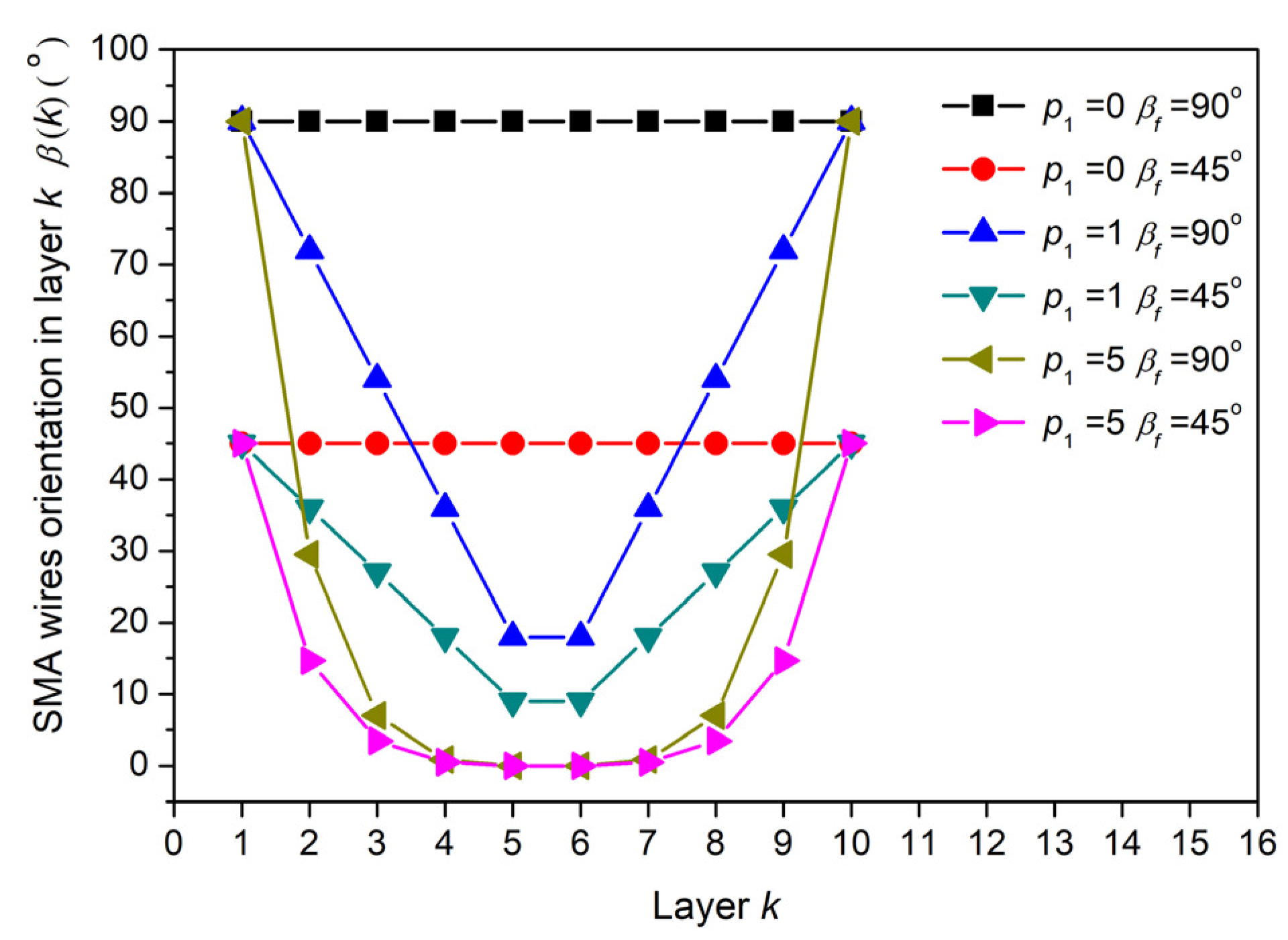
This section focuses on the influence of orientation distribution of SMA wires on the natural frequency of composite laminates. According to schematic 1, the orientation of SMA wires moves along the Z axis in the positive direction with the variation of layers. On the contrary, the orientation of SMA wires moves clockwise along the negative direction of the Z axis with the variation of layers. As shown in Figure 3, the orientation distribution of SMA wires in composite laminates can be obtained from Equation (1) at the p 1 of 0, 1, and 5 when β f is taken as 90 °C and 45 °C, respectively. With the increase in p 1 value, more SMA wires orientation tend to X direction, and the increase in β f results in the larger span of SMA wires towards distribution.
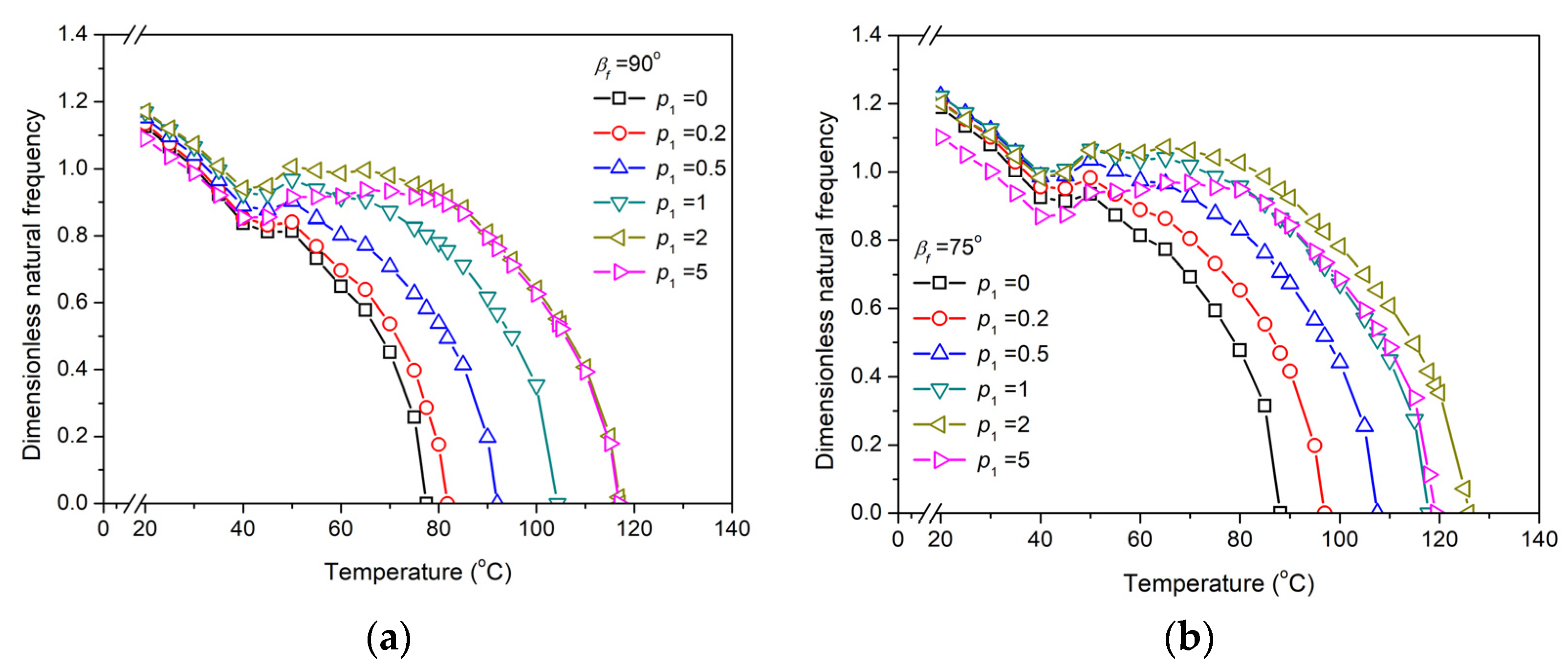
The natural frequency composite laminates with variation of temperature under p 1 , which takes 0, 0.2, 0.5, 1, 2, and 5 subjected to β f at 90°, 70°, 60°, and 45°, are investigated as shown in Figure 4.
Figure 4a depicts the dimensionless natural frequency of composite laminates under different p 1 when β f = 90°. As the temperature rises, the natural frequencies corresponding to different p 1 change trends from basically similar to gradually separated. In the low-temperature range of 15 °C to 40 °C, the natural frequency decreases rapidly as the temperature increases. The decrease in the natural frequency is due to the increase in thermal stress caused by the large modulus of graphite, which plays a leading role in the stiffness of composite laminates. Simultaneously, the recovery stress generated by the SMA pre-strain induced at a temperature below 40 °C is generally less than 100 MPa, as shown in Figure 2, which has a weak influence on the stiffness of composite laminates [21]. Although the gradient distribution of the SMA wires orientation leads to differences in the recovery force of each layer, the overall recovery force of the composite laminates along the X-axis direction is still less, so the effect of pre-strain on the stiffness of the composite laminates can be ignored. As the temperature ranges from 40 °C to 75 °C, recovery stress induced by SMA pre-strain is higher than the thermal stress that is produced by graphite and epoxy. The recovery force in the composite laminates plays a dominant role in increasing the stiffness, thus increasing the natural frequency with increasing temperature. With the continuous increase in temperature, the recovery stress basically stabilizes, and the thermal stress plays a leading role again, resulting in the natural frequency of the composite laminates again being reduced until buckling occurs. In addition, Figure 4a shows that the gradient orientation of the SMA wires has a significant effect on the natural frequency of the p 1 mainly after the temperature is higher than 40 °C. The natural frequency increases with the increase in p 1 after the temperature rises to 65 °C, and the difference in the increase in the natural frequency is no longer obvious until p 1 is greater than 2. It is worth noting that the highest natural frequency corresponding to p 1 = 2 and the critical buckling temperature T c r is positively correlated with p 1 .
From Figure 4a–d, it can be seen that β f in the range of 45° to 90° is inversely proportional to the critical buckling temperature of the composite laminates, i.e., T c r ( β f = 45 ° ) > T c r ( β f = 60 ° ) > T c r ( β f = 75 ° ) > T c r ( β f = 90 ° ) . Concurrently, the decrease in β f weakens the influence of p 1 on the natural frequency. For instance, at a certain temperature, the difference between the natural frequencies of several p 1 at β f = 45 ° is significantly less than that at β f = 75 ° and β f = 90 ° . The primary reason is that the decrease in β f leads to a smaller included angle between the SMA wires in the adjacent layers, resulting in no noteworthy effect of the p 1 on the orientation of the wires. In addition, p 1 = 0, i.e., the SMA wires orientation of each layer in the composite laminates is at β f or − β f , which is consistent with the traditional form of the anti-symmetric oblique composite laminates. Although embedded SMA wires with the same orientation in the composite laminates do not have a gradient distribution, this reduces the ability to adjust the modal frequency to a certain extent. However, the elastic modulus of SMA and the generated in-plane force will have a more concentrated effect on the stiffness of the composite laminate. Only from the material point of view, the influence of SMA on the natural frequency of the composite laminate is still quite significant.
Figure 5a–d reveal that the natural frequency of the composite laminates varies greatly with the change of β f when p 1 = 0. β f decreases from 90 ° to 45 ° at a temperature of 65 °C, corresponding to the increase in the dimensionless natural frequency from 0.58 to 1.15. At a temperature of 85 °C, the composite laminates with the β f at 90 ° has already buckled, and the dimensionless natural frequency with β f at 75 ° , 60 ° , and 45 ° is 0.31, 0.82, and 1.03 respectively. Therefore, the decrease in p 1 leads to a more significant influence of β f on the dimensionless natural frequency. In addition, temperature is negatively related to natural frequency.
The dimensionless natural frequency increases temporarily with the increase in p 1 as the temperature is greater than 45 °C. Maximum dimensionless natural frequency occurs at p 1 = 2 when β f is 90 ° and 75 ° . For β f values of 90 ° and 75 ° , more SMA wires’ orientations in the composite laminates are tilted towards the X-axis, resulting in an increase in the recovery force of the composite laminates, thus increasing the dimensionless natural frequency. When the temperature is 25 °C, the maximum natural frequency appears at p 1 = 1. With further increase in p 1 , the natural frequency generally tends to decrease. Due to the smaller recovery force caused by pre-strain at normal temperature, the effect proportion of elastic modulus on stiffness increases, while the effect of β f on natural frequency weakens.

3.3. Influence of Gradient Distribution Parameter of SMA Volume Fraction p 2

The influence of the gradient distribution of SMA wires volume fraction in the composite laminate on the natural frequency is examined with a certain total SMA content. In this section, p 2 is invoked as a gradient distribution parameter for the volume fraction of SMA wires. Figure 6 displays the gradient distribution of SMA wires volume fraction that p 2 is taken as −4, −3, −2, −1, 0, 1, 2, 3, and 4, respectively, where the gradient distribution of SMA wires volume fraction in each layer is achieved by Equations (2) and (3).
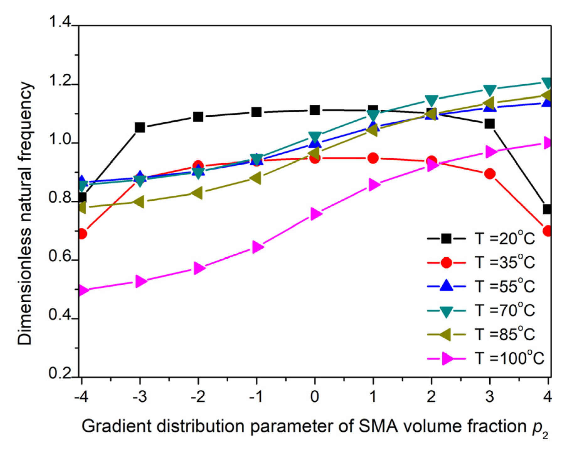
The gradient distribution of SMA wires volume fraction in composite laminates is classified as negative gradient distribution ( p 2 < 0 ), uniform distribution ( p 2 = 0 ) and positive gradient distribution ( p 2 > 0 ) according to p 2 classification. Figure 7a,b show the variation of dimensionless natural frequencies with temperature under p 2 0 and p 2 0 conditions. Figure 8 depicts the dimensionless natural frequencies of composite laminates with p 2 at temperatures of 20 °C, 35 °C, 55 °C, 70 °C, 85 °C, and 100 °C.
Figure 7a,b show that the dimensionless natural frequency gradually decreases with increasing temperature in the low temperature range of 15 °C to 45 °C. The main reason for this phenomenon is that the elastic modulus and recovery stress of SMA are less at normal temperatures, while the elastic modulus of graphite and epoxy matrix plays a major role. With the increase in temperature, the thermal stress of the substrate increases, and the dimensionless natural frequency decreases with the increase in temperature.
In the temperature range from 15 °C to 45 °C, the p 2 has no significant effect on the dimensionless natural frequency, except when p 2 = ±4 decreases the natural frequency obviously. Since the SMA has an extremely uneven gradient distribution corresponding to p 2 = ±4, and the content of graphite in the matrix is also less, the composite modulus of some layers in the composite laminates is reduced, resulting in a significant reduction in the dimensionless natural frequency.
In the temperature range from 45 °C to 155 °C, the dimensionless natural frequency increases first with the increase in temperature and then decreases gradually until the frequency decreases to zero. Within this temperature range, the recovery stress caused by SMA wires pre-strain in composite laminates has a greater effect on stiffness than the thermal stress of the matrix, i.e., the recovery stress of SMA plays a dominant role. When the temperature rises to 80 °C, the recovery stress tends to be relatively stable. As the temperature continues to rise, the thermal stress of the matrix again dominates, and the natural frequency further decreases. In addition, the p 2 has a significant influence on the natural frequency in the high temperature region. Compared with Figure 7a,b, the dimensionless natural frequency of composite laminates with uniform volume fraction of SMA wires is higher than the negative gradient distribution and lower than the positive gradient distribution.
Figure 8 further depicts that the dimensionless natural frequency increases with the increase in p 2 as the temperature is higher than 45 °C. When the volume fraction of the SMA wires has a positive gradient distribution, the SMA wire mainly concentrates on the top and bottom layers of the composite laminates, which increases the bending rigidity of the composite laminate relatively, thus increasing the natural frequency of the composite laminate. When the distribution has a negative gradient, SMA wires are mainly concentrated in the middle layer of the composite laminates, which makes the bending rigidity of the composite laminates relatively reduced and the natural frequency reduced.
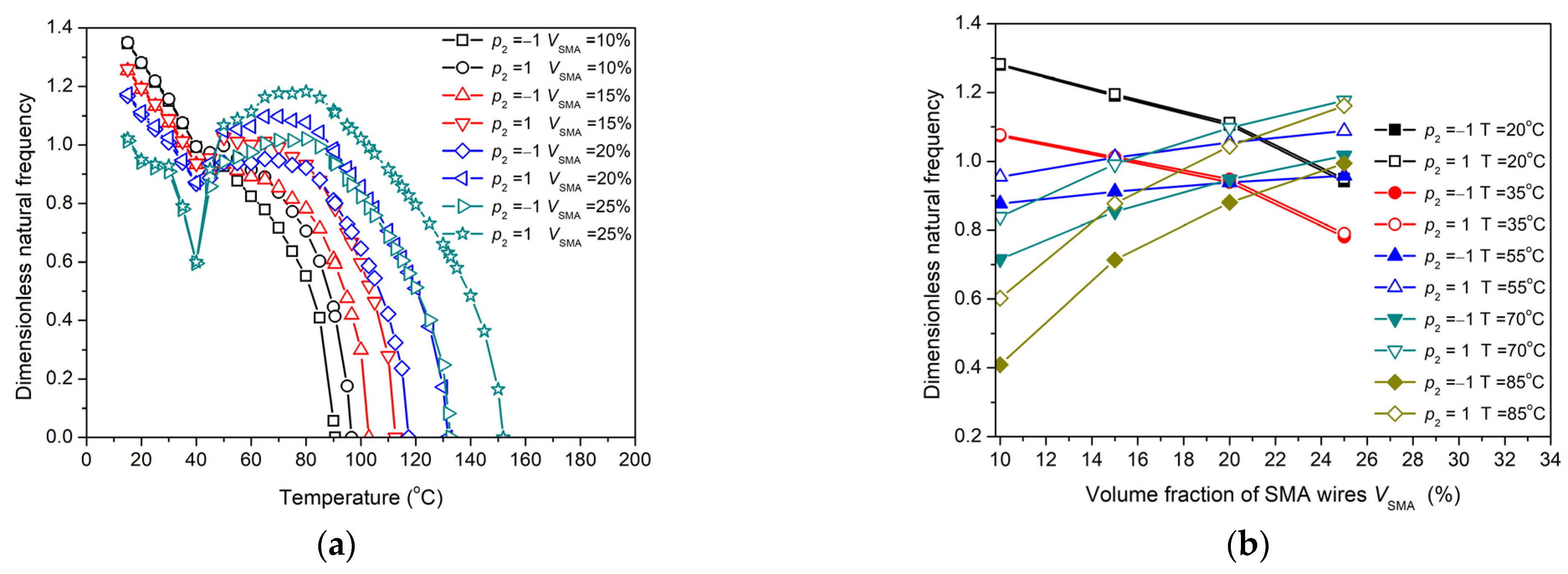
Figure 9a depicts the variation of dimensionless natural frequency with temperature as the volume fraction of SMA takes 10%, 15%, 20%, and 25% at p 2 = ±1. Figure 9b shows the variation of dimensionless natural frequency with the volume fraction of SMA corresponding to p 2 = ±1 at temperatures of 20 °C, 35 °C, 55 °C, 70 °C, 85 °C, and 100 °C. By means of Figure 9a,b, the dimensionless natural frequencies corresponding to p 2 = −1 and p 2 = +1 are close in the temperature range of 15 °C to 45 °C, and the volume fraction of SMA wires is negatively correlated with the natural frequency.
Figure 9a indicates that, at high temperatures above 80 °C, the bending stiffness of p 2 = +1 corresponding to the same volume fraction of SMA wires is higher than that of p 2 = −1, so that the dimensionless natural frequency and critical buckling temperature corresponding to p 2 = +1 are both higher. As the volume fraction of SMA wires increases, the recovery stress and natural frequency of SMA wires are also positively correlated with the critical buckling temperature.
According to Figure 9b, the dimensionless natural frequency increases with the increase in SMA volume fraction at temperatures above 55 °C. In addition, due to the relative stability of the recovery stress at constant temperature, the dimensionless natural frequency increases with the volume fraction of SMA wires in a relatively linear slope trend, and the dimensionless natural frequency of p 2 = +1 is higher than that of p 2 = −1.

3.4. Influence of Anti-Symmetric Oblique Coupling Gradient Distribution of SMA

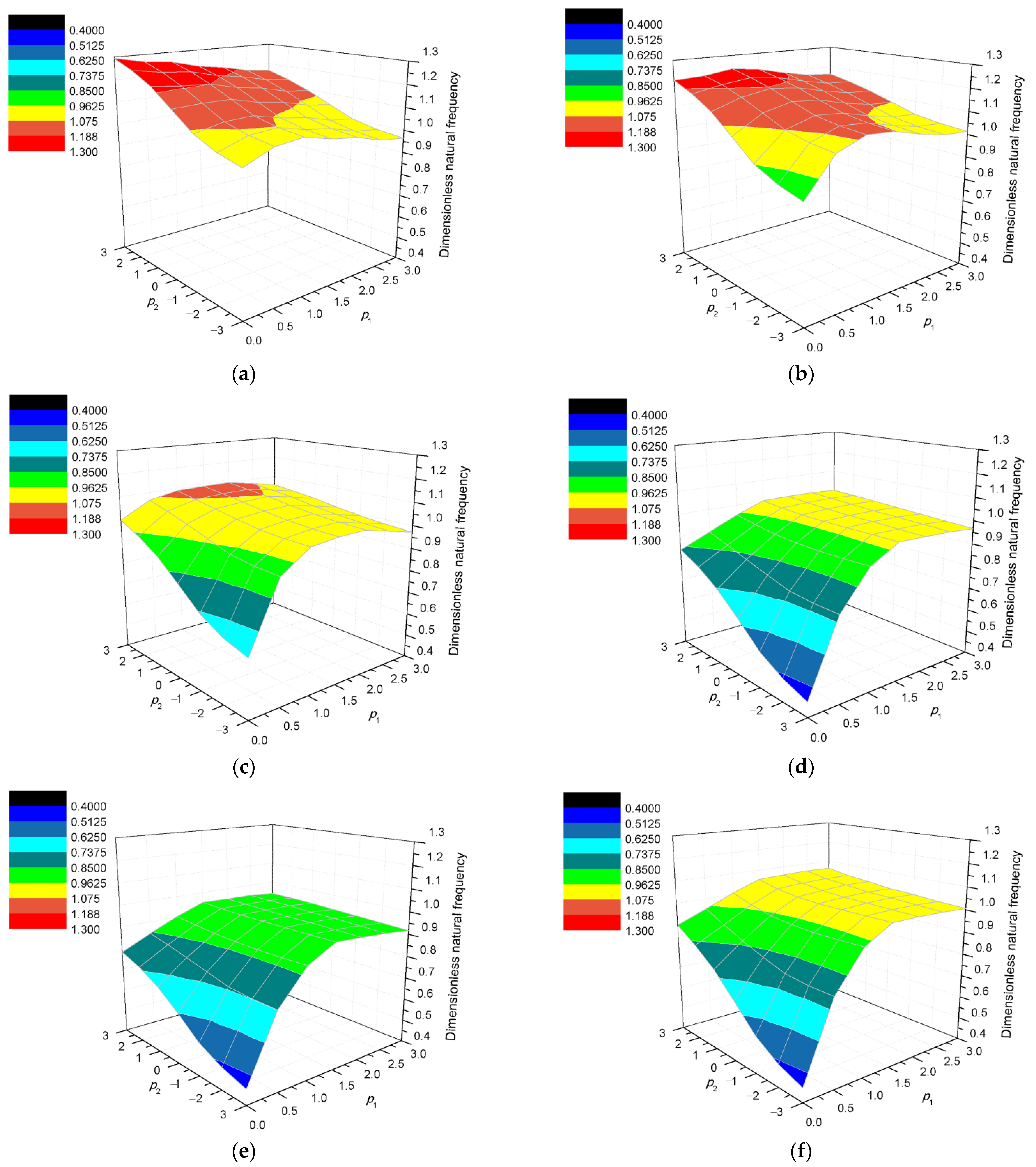
Figure 10 shows the anti-symmetric oblique coupling effect of SMA wires’ orientation gradient distribution and SMA volume fraction gradient distribution on natural frequencies in composite laminates. Figure 10a–d describe the increase in the maximum natural frequency as the β f of the SMA wire increases. The maximum dimensionless natural frequency at β f = 45 ° is significantly higher than that at β f = 90 ° . When the β f is constant, the dimensionless natural frequency decreases with the decrease in p 1 and p 2 . For example, p 1 = 0 and p 2 = −3 correspond to the smallest dimensionless natural frequency. With the increase in p 1 and p 2 , the dimensionless natural frequency increases gradually.
As shown in Figure 10d, the increment of the dimensionless natural frequency induced by the increase in p 1 is faster than the increase in the dimensionless natural frequency caused by the increase in p 2 when β f = 90 ° , and only the increase in p 1 can increase the dimensionless natural frequency of the composite laminate to the maximum.
The effect of p 2 on the increase in dimensionless natural frequency increases significantly with the decrease in β f . For example, when β f = 75 ° , the maximum dimensionless natural frequency appears in the area where p 1 = (0.75~2.4) and p 2 = (1~3) intersect, and when β f = 45 ° , the maximum dimensionless natural frequency is distributed in the area of p 2 = (1~3).
Figure 10d–f show the anti-symmetric oblique coupling effect of p 1 and p 2 at β f = 90 ° under different SMA volume fraction conditions such as 20%, 15%, and 25%. With the constant gradient distribution combination ( p 1 , p 2 ), the natural frequency increases with the volume fraction of SMA wires in the composite laminates. The influence of p 1 on dimensionless natural frequency is greater than that of p 2 when β f = 90 ° . By altering p 1 , dimensionless natural frequency can be adjusted more effectively.

4. Experiment Validation

4.1. Prepared Experimental Samples

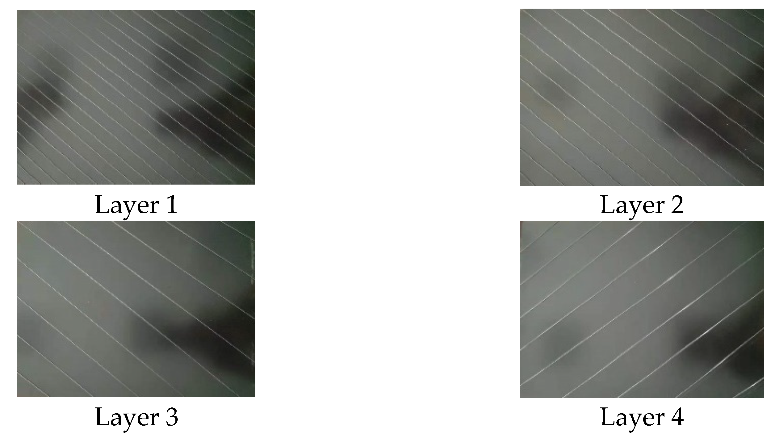
To verify the theoretical formula accuracy of this study, two composite laminate samples embedded with SMA wires were fabricated in this research. Composite laminates samples were fabricated in which SMA wires were embedded in two gradient distributions: symmetric orthogonal gradient distribution and anti-symmetric oblique gradient distribution. The sample matrices consisted of graphite and epoxy composite layers. SMA wires were assembled by hand lay-up between the layers. Subsequently, the contact interface was filled by a solution deployed by 325 mesh graphite powders and YDF-170 epoxy resin supplemented with 2-ethyl-4-methylimidazole curing agent at 6% mass ratio. The curing process of hardening the contact interface filling between layers required approximately 15 min with external heating at 60 °C. The length and width of composite laminates were 400 mm and 300 mm, respectively. Six layers were laid, each with a thickness of 2 mm. Table 2 and Table 3 show the laying parameters of symmetric orthogonal and antisymmetric oblique laying of SMA wires in composite laminates, respectively. The laying pattern of the SMA wires laying diagonally in each layer is shown in Figure 11.
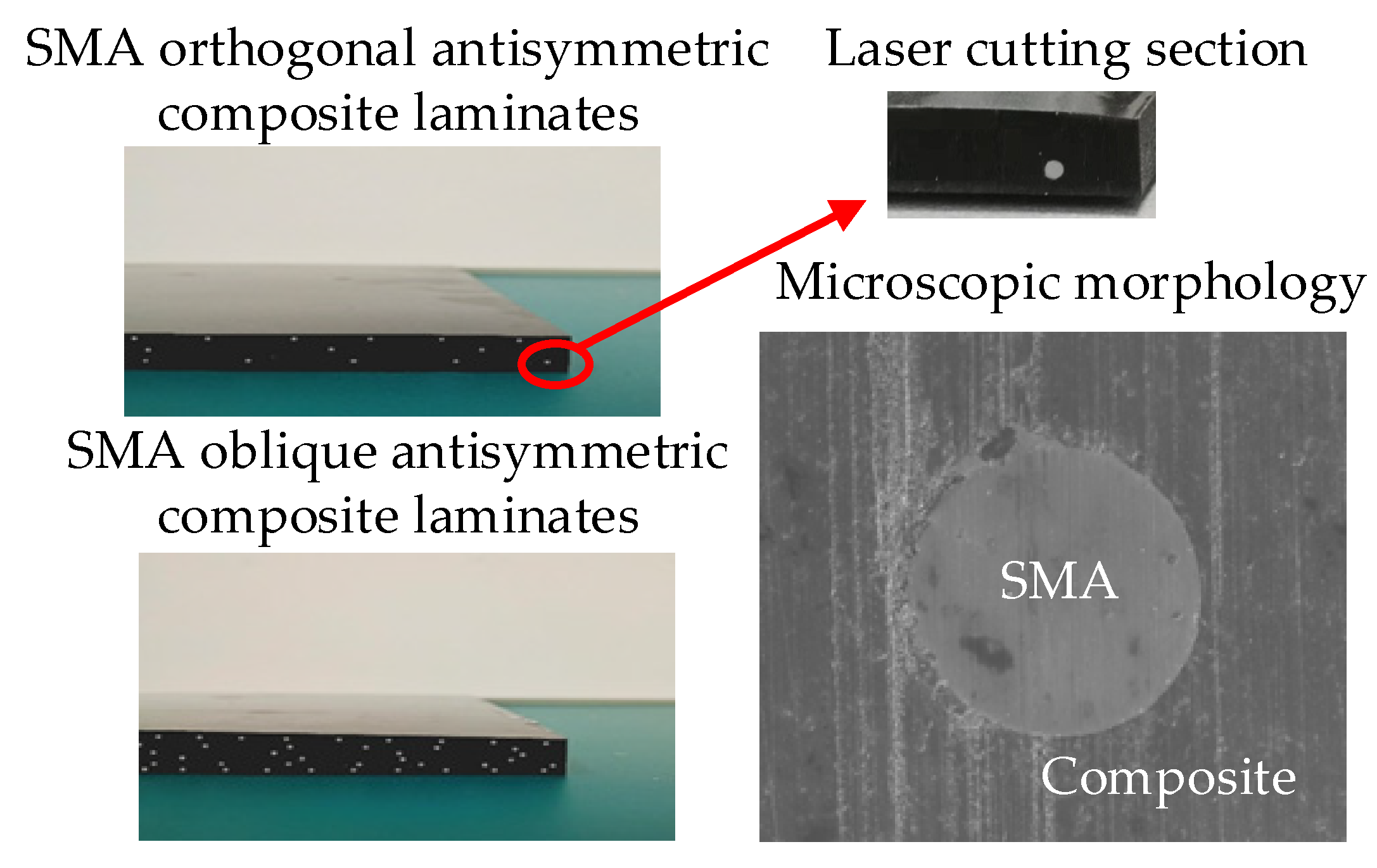
SMA symmetric orthogonal composite laminates and SMA anti-symmetric oblique composite laminates are given in Figure 12. Laser cutting and polishing the section of the intercepted end section of the composite laminate are performed. Surface morphology of laser cut section was observed by field radiation scanning electron microscope. The microscopic view of Figure 12 shows that SMA wires are relatively well connected to the substrate.

4.2. Experimental Equipment and Testing

The modal test in this study adopts the Belgian LMS dynamic test system, which includes hardware such as SC316 data acquisition front-end, ICP accelerometer, multi-type hammer with ICP, and Test Lab software modules such as Impact Testing and Modal Analysis. Then the modal experiment was carried out by the hammering method. Figure 13a,b depict the steady-state diagrams of the frequency response of SMA symmetric orthogonal composite laminates and SMA anti-symmetric oblique composite laminates obtained through modal experiments, respectively.
Theoretical modal calculations were performed on the experimental samples according to the actual material parameters to compare the theoretical and experimental results, thereby verifying the correctness of the theoretical methods. The results of experimental tests and theoretical calculations, including natural frequencies and modal shapes, are shown in Figure 14 and Table 4.
A comprehensive analysis of Figure 14 and Table 4 shows that
(1) For SMA symmetric orthogonal composite laminates, the theoretical values and experimental results of the first five orders of natural frequencies are generally well fitted, with a maximum error of less than 7%. In particular, the error of first-order mode frequency is less than 3.5%, which indicates that the fitting accuracy of theoretical value and experimental result of the natural frequency is high.
(2) For SMA anti-symmetric oblique composite laminates, the errors of the first-order natural frequency theory and experimental results are slightly larger than those of the SMA symmetric orthogonal composite laminates, and the other frequency errors are basically the same.
(3) From the numerical comparison between the experimental results of the natural frequencies of SMA symmetric orthogonal composite laminates and SMA anti-symmetric oblique composite laminates with theoretical prediction values, it can be found that the experimental values of the first five orders are all lower than the theoretical values. That is to say, the actual stiffness of composite laminates is smaller than the theoretical stiffness, which may be because the firmness of the SMA wire and the substrate during the sample production process did not reach the desired level, resulting in the actual stiffness value being slightly lower.

5. Conclusions

For suppressing resonance, anti-symmetric oblique gradient composite laminates with embedded SMA wires consider internal forces, i.e., SMA pre-strain recovery force and thermal expansion force of the matrix. The correlation between material structural parameters and modal properties of the composite laminates is analyzed by numerical calculation of the eigenvalue equation and verified by experiments. The main conclusions are as following:
  • During the heating process, the SMA wires distributed in the form of anti-symmetric oblique positive gradient can fully exert the recovery stress generated by SMA tensile pre-strain, i.e., effectively improve the stiffness of the composite laminates.
  • The natural frequency and the critical buckling temperature of SMA composite laminates with anti-symmetric oblique positive gradient distribution are higher than that of composite laminates with anti-symmetric oblique uniform/negative gradient distribution and symmetric orthogonal gradient distribution.
  • Coupling gradient composite laminates embedded with SMA wires have the coupling design ability of gradient structure and material components, mainly from two aspects: gradient distribution of SMA wires orientation and gradient distribution of SMA volume fraction. The proposed structure effectively broadens the frequency modulation range, which makes the fine regulation of the natural frequency and critical buckling temperature feasible.

Author Contributions

Conceptualization, Y.H. and Y.S.; methodology, Y.H.; software, Y.H.; validation, Y.H. and Y.S.; formal analysis, Y.H.; writing—original draft preparation, Y.H.; writing—review and editing, Y.S. All authors have read and agreed to the published version of the manuscript.

Funding

This work was financially supported by the National Natural Science Foundation of China (NSFC) under Grant Nos 51575201 and the Liuzhou Science and Technology Planning Project under Grant Nos 2020GAAA0403.

Institutional Review Board Statement

Not applicable.

Informed Consent Statement

Not applicable.

Conflicts of Interest

The authors declare no conflict of interest.

References

  1. Ro, J.; Baz, A. Nitinol-reinforced plates: Part I. Thermal characteristics. Compos. Eng. 1995, 5, 61–106. [Google Scholar] [CrossRef]
  2. Mohd Jani, J.; Learya, M.; Subica, A.; Gibsonc, M.A. A review of shape memory alloy research, applications and opportunities. Mater. Des. 2014, 56, 1078–1113. [Google Scholar] [CrossRef]
  3. Dauksher, R.; Patterson, Z.; Majidi, C. Characterization and analysis of a flexural shape memory alloy actuator. Actuators 2021, 10, 202. [Google Scholar] [CrossRef]
  4. Fallah, A.; Dehkordi, M.B. A new nonlinear finite element model for transient dynamic response of a micro composite plate embedded with micro SMA wires considering the size effects. Mech. Adv. Mater. Struc. 2021, 10, 1–22. [Google Scholar] [CrossRef]
  5. Amiri, A.; Mohammadimehr, M.; Irani Rahaghi, M. Vibration analysis of a micro-cylindrical sandwich panel with reinforced shape-memory alloys face sheets and porous core. Eur. Phys. J. Plus 2020, 136, 20. [Google Scholar] [CrossRef]
  6. Chiker, Y.; Mourad, B.; Bouaziz, S.; Mouloud, G.; Amar, M.B.; Haddar, M. Free vibration analysis of hybrid laminated plates containing multilayer functionally graded carbon nanotube-reinforced composite plies using a layer-wise formulation. Arch. Appl. Mech. 2020, 91, 463–485. [Google Scholar] [CrossRef]
  7. Mehar, K.; Mishra, P.K.; Panda, S.K. Numerical investigation of thermal frequency responses of graded hybrid smart nanocomposite (CNT-SMA-Epoxy) structure. Mech. Adv. Mater. Struc. 2021, 28, 2242–2254. [Google Scholar] [CrossRef]
  8. Karimimahabadi, R.; Daneshpazhooh, M.; Shakeri, M. On the free vibration and design optimization of a shape memory alloy hybrid laminated composite plate. Acta Mech. 2021, 232, 1–21. [Google Scholar] [CrossRef]
  9. Rogers, C.A. Active vibration and structural acoustic control of shape memory alloy hybrid composites: Experimental results. J. Acoust. Soc. Am. 1990, 88, 2803. [Google Scholar] [CrossRef] [Green Version]
  10. Rogers, C.A.; Liang, C.; Jia, J. Structural modification of simply-supported laminated plates using embedded shape memory alloy fibers. Comput. Struct. 1991, 38, 569–580. [Google Scholar] [CrossRef]
  11. Ostachowicz, W.; Krawczuk, M.; Zak, A. Natural frequencies of a multilayer composite plate with shape memory alloy wires. Finite Elem. Anal. Des. 1999, 32, 71–83. [Google Scholar] [CrossRef]
  12. Mahabadi, R.K.; Shakeri, M.; Danesh, P.M. Free vibration of laminated composite plate with shape memory alloy fibers. Lat. Am. J. Solids Struct. 2016, 13, 314–330. [Google Scholar] [CrossRef] [Green Version]
  13. Malekzadeh, K.; Mozafari, A.; Ghasemi, F.A. Free vibration response of a multilayer smart hybrid composite plate with embedded SMA wires. Lat. Am. J. Solids Struct. 2014, 11, 279–298. [Google Scholar] [CrossRef] [Green Version]
  14. Lal, A.; Markad, K. Thermal post buckling analysis of smart SMA hybrid sandwich composite plate. Polym. Polym. Compos. 2021, 29, 344–360. [Google Scholar] [CrossRef]
  15. Yas, M.H.; Basati, F.; Kamarian, S. Thermal buckling of trapezoidal composite laminated plates with embedded shape memory alloys. Polym. Compos. 2021, 42, 3349–3362. [Google Scholar] [CrossRef]
  16. Kuo, S.Y.; Shiau, L.C.; Chen, K.H. Buckling analysis of shape memory alloy reinforced composite laminates. Compos. Struct. 2009, 90, 188–195. [Google Scholar] [CrossRef]
  17. Rostamijavanani, A.; Ebrahimi, M.R.; Jahedi, S. Thermal post-buckling analysis of laminated composite plates embedded with shape memory alloy fibers using semi-analytical finite strip method. J. Fail. Anal. Prev. 2020, 21, 290–301. [Google Scholar] [CrossRef]
  18. Fani, M.; Taheri-Behrooz, F. Analytical study of thermal buckling and post-buckling behavior of composite beams reinforced with SMA by Reddy Bickford theory. J. Intell. Mater. Syst. Str. 2020, 33, 121–135. [Google Scholar] [CrossRef]
  19. Kamarian, S.; Shakeri, M. Thermal buckling analysis and stacking sequence optimization of rectangular and skew shape memory alloy hybrid composite plates. Compos. Part. B -Eng. 2017, 115, 137–152. [Google Scholar] [CrossRef]
  20. Asadi, H.; Kiani, Y.; Aghdam, M.; Shakeri, M. Enhanced thermal buckling of laminated composite cylindrical shells with shape memory alloy. J. Compos. Mater. 2015, 50, 243–256. [Google Scholar] [CrossRef]
  21. Huang, Y.; Zhang, Z.; Li, C.; Mao, K.; Huang, Q. Modal Performance of Two-Fiber Orthogonal Gradient Composite Laminates Embedded with SMA. Materials 2020, 13, 1102. [Google Scholar] [CrossRef] [PubMed] [Green Version]
  22. Huang, Y.; Li, L.; Xu, Z.; Li, C.; Mao, K. Free Vibration Analysis of Functionally Gradient Sandwich Composite Plate Embedded SMA Wires in Surface Layer. Appl. Sci. 2020, 10, 3921. [Google Scholar] [CrossRef]
  23. Shariyat, M.; Hosseini, S.H. Accurate eccentric impact analysis of the preloaded SMA composite plates based on a novel mixed-order hyperbolic global-local theory. Compos. Struct. 2015, 124, 140–151. [Google Scholar] [CrossRef]
  24. Sun, M.; Wang, Z.; Yang, B. Experimental investigation of GF/epoxy laminates with different SMAs positions subjected to low-velocity impact. Compos. Struct. 2017, 171, 170–184. [Google Scholar] [CrossRef]
  25. Asadi, H.; Akbarzadeh, A.; Wang, Q. Nonlinear thermo-inertial instability of functionally graded shape memory alloy sandwich plates. Compos. Struct. 2015, 120, 496–508. [Google Scholar] [CrossRef]
  26. Miyazaki, E.; Watanabe, Y. Development of Shape Memory Alloy Fiber Reinforced Smart FGMs. Mater. Sci. Forum. 2003, 423, 107–112. [Google Scholar] [CrossRef]
  27. Xue, L. Theoretical Analysis of Functionally Graded Shape Memory Alloy Beam Subjected to Pure Bending. Chin. J. Mech. Eng. 2012, 48, 40. [Google Scholar] [CrossRef]
  28. Shariat, B.S.; Meng, Q.; Mahmud, A.S. Functionally graded shape memory alloys: Design, fabrication and experimental evaluation. Mater. Des. 2017, 124, 225–237. [Google Scholar] [CrossRef]
  29. Viet, N.; Zaki, W.; Umer, R. Analytical model of functionally graded material/shape memory alloy composite cantilever beam under bending. Compos. Struct. 2018, 203, 764–776. [Google Scholar] [CrossRef]
Figure 1. Schematic diagram of composite laminate embedded with coupling gradient SMA.
Symmetry 14 00361 g001
Figure 2. SMA modulus of elasticity and recovery stress vs. temperature.
Symmetry 14 00361 g002
Figure 3. Gradient distribution of SMA wires orientation in composite laminates.
Symmetry 14 00361 g003
Figure 4. Temperature-dependent dimensionless natural frequency of different gradient distribution parameter of SMA wires orientation p 1 : (a) β f = 90 ° ; (b) β f = 75 ° ; (c) β f = 60 ° ; (d) β f = 45 ° .
Symmetry 14 00361 g004aSymmetry 14 00361 g004b
Figure 5. Variation of dimensionless natural frequency with gradient distribution parameter of SMA wires orientation p 1 at different temperatures: (a) T = 25 °C; (b) T = 45 °C; (c) T = 65 °C; (d) T = 85 °C.
Symmetry 14 00361 g005
Figure 6. Gradient distribution of SMA volume fraction in composite laminates.
Symmetry 14 00361 g006
Figure 7. Temperature-dependent dimensionless natural frequency of different gradient distribution parameter of SMA volume fraction p 2 : (a) p 2 0; (b) p 2 0.
Symmetry 14 00361 g007
Figure 8. Variation of dimensionless natural frequency with gradient distribution parameter of SMA volume fraction p 2 at different temperatures.
Symmetry 14 00361 g008
Figure 9. Influence of SMA volume fraction on dimensionless natural frequency at p 2 = ± 1: (a) temperature dependent dimensionless natural frequencies of different volume fractions of SMA; (b) variation of dimensionless natural frequency with volume fraction of SMA at different temperatures.
Symmetry 14 00361 g009
Figure 10. Dimensionless natural frequency distribution of coupling gradient coupling effect under different β f and V SMA conditions: (a)   β f = 45 ° ,   V SMA = 20%; (b) β f = 60 ° ,   V SMA = 20%; (c) β f = 75 ° ,   V SMA = 20%; (d) β f = 90 ° ,   V SMA = 20%; (e) β f = 90 ° ,   V SMA = 15%; (f) β f = 90 ° ,   V SMA = 25%.
Symmetry 14 00361 g010
Figure 11. Laying distribution of SMA wires in antisymmetric oblique composite laminates.
Symmetry 14 00361 g011aSymmetry 14 00361 g011b
Figure 12. Prepared experimental samples of composite laminates embedded with SMA wires.
Symmetry 14 00361 g012
Figure 13. Frequency response steady state diagram of composite laminates: (a) SMA wires are embedded symmetric orthogonally; (b) SMA wires are embedded anti-symmetric oblique.
Symmetry 14 00361 g013
Figure 14. Natural frequency and mode shape of the first three modes: (a) SMA symmetric orthogonal composite laminates; (b) SMA antisymmetric oblique composite laminates.
Symmetry 14 00361 g014
Table 1. Material properties of the SMA, graphite, and epoxy [13].
E ( GPa ) G ( G P a ) v ρ ( k g · m 3 ) α ( 1 / °C )
SMAFrom Figure 2-0.3645010.26 × 10−6
Graphite275.6114.80.2190024.40 × 10−6
Epoxy3.431.270.35125064.80 × 10−6
Table 2. Laying parameters of SMA symmetric orthogonal composite laminates.
Layer
k
SMA Wire Length
l
SMA Wires Nos
n
Laying Spacing
l/mm
SMA Volume Fraction
Vs/%
14001327.646.85
23001320.055.13
3400656.283.08
4300736.632.72
54001035.455.17
63001814.847.05
Table 3. Laying parameters of SMA antisymmetric oblique composite laminates.
Layer
k
SMA Wires Nos
n
SMA Volume Fraction
Vs/%
1236.95
2155.15
392.90
492.90
5155.15
6236.95
Table 4. Comparison of theoretical predictions and experimental results of natural frequency for composite laminates.
Distribution Form Mode Order
(1,1)(2,1)(1,2)(3,1)(2,2)
symmetric
orthogonal
Experimental results 168.7389.7479.8632730.2
Theoretical predictions 174.6364.5507.6667.7745.5
Error3.49%6.47%5.79%5.65%2.10%
antisymmetric obliqueExperimental results 172.2385.6524.6707.9789
Theoretical predictions 182.4406.3556.2718.9793.1
Error5.92%5.37%6.02%1.55%5.19%
Publisher’s Note: MDPI stays neutral with regard to jurisdictional claims in published maps and institutional affiliations.