Article

Semi-Analytical Method for Unsymmetrical Doublet Flow Using Sink- and Source-Dominant Formulation

1
Department of Mechanical Engineering, Faculty of Engineering, Technology, and Built Environment, UCSI University, Kuala Lumpur 56000, Malaysia
2
Malaysia-Japan International Institute of Technology, Universiti Teknologi Malaysia, Kuala Lumpur 56000, Malaysia
3
Department of Civil Engineering, Lee Kong Chian Faculty of Engineering and Science, Universiti Tunku Abdul Rahman, Kajang 43000, Malaysia
4
Faculty of Engineering, School of Mechanical Engineering, Universiti Teknologi Malaysia, Skudai 81310, Malaysia
*
Authors to whom correspondence should be addressed.
Symmetry 2022, 14(2), 391; https://doi.org/10.3390/sym14020391
Submission received: 30 November 2021 / Revised: 29 December 2021 / Accepted: 7 January 2022 / Published: 16 February 2022
(This article belongs to the Section Mathematics)

Abstract

:
Potential flow formed by doublet flow has been well applied in environmental applications and geothermal designs such as reservoir and fuel injectors. Most of the doublet flow is assumed based on the sink and source with equivalent strength and distance from the origin, forming the well-known Rankine oval structure when a far-field flow is superposed. A semi-analytical method is formulated to systematically investigate the unsymmetrical doublet flow with different strengths of sink and source. The general mathematical expression for unsymmetrical doublet flow is derived analytically before the streamline and the potential line can be visualised via a numerical approach. The results revealed that the doublet flows altered the Rankine oval structure to form aerofoil-like geometry. When the far-field flow interferes with the general Doublet configuration, unique flow structures such as convex, concave, and various wing shapes could be generated. The current study provides new insight on producing aerodynamic curves for the design of bio-inspired structures.

1. Introduction

Potential flow is an idealised flow characterised by its irrotationality and negligible viscous effect, while the flow remains continuously incompressible [1]. The flow potential was introduced by Leonard Euler in 1752 [2], in which the velocity vector can be defined as the divergence of velocity potential ϕ, which could lead to Laplace equation upon combining with the Continuity equation:
2 ϕ = 0
Despite its long-standing history in investigating fundamental classical fluid mechanics, potential flow remains the research interest of the fluid dynamics fraternity. It is important as it has been widely applied in environmental flows, the visualisation of fluid flow, and the generation of initial flow conditions [3]. One of the notable examples of environmental flow is the estimation of groundwater flow, which is critical for tunnelling construction [4], groundwater extraction [5,6], and contamination prediction [7]. A massive number of works on the numerical simulation of groundwater flow have been reported. Xie et al. [8] applied a multiscale finite element method for groundwater flow in heterogeneous media. The application of the Monte Carlo method in similar research was reported by Xia et al. [9]. Moreover, meshfree techniques are gaining attention in the simulation of groundwater flow, and the literature reported includes the meshfree collocation method [5,6], element-free Galerkin method [10], meshless local Petrov–Galerkin method [11], and immersed boundary method [12]. Other environmental flows which require the application of potential flow theory are groundwater-surface water interaction [13], granular flow [14], and interface flow [15].
The potential flow theory is widely used in various man-made technological applications. Potential flow theory was additionally applied by Liu et al. [16] and Magdalena and Firdaus [17] to investigate the hydroelastic response of floating structure and flow across a permeable wavy bed, respectively. Chen and Price [18] analytically studied the potential flow of a hydrofoil near a water surface. Recently, Frayssinhes et al. [19] also presented an interesting model based on potential flow theory, which is able to predict the local fibre orientation of veneers. Meanwhile, Sahin and Hyman [20] and Huggins and Packwood [21] manipulated the potential flow panel method to optimise the shape of an autonomous submersible. An analysis on the generation of wave drag due to a moving Rankine ovoid in stratified fluid was reported by Xu et al. [22]. Suner et al. [23] investigated similar topics by looking into the hydrodynamics of the perforated Rankine ovoid. Raven [24], who improvised the procedure of ship resistance testing on shallow water, involved potential panel analysis. Such theory was further applied by Roisman et al. [25], Rubin et al. [26], and Rubin [27] to develop models for mechanics of penetrations on elastic-plastic materials. Furthermore, the Rankine oval structure can be used as a structural modification for minimising mechanical damping in fluid-structure interaction [28].
The studies mentioned above reveal most of the potential flow with practical applications involve a Rankine oval flow structure or the combination of uniform flow and source–sink elements. Where only a source–sink flow configuration is concerned, the flow is known as doublet flow. Perhaps, there are quite some direct applications of doublet flow reported. For instance, doublet flow was applied by Cola et al. [29] to improve microfluidic mixing, while Basu and Gianchandani [30] altered the fluids’ surface tension as a strategy to create the microfluidic doublet configuration. The surface tension driven doublet flow can be observed in solutocapillary Marangoni flow, and the physics of the flow was detailed by Benouaguef et al. [31]. The formation of doublet flow was found as an essential factor in disrupting superfluidity as the paired vortex would induce impurities interaction [32]. The doublet system also can be observed in the design of geothermal reservoirs as a source of renewable energy, and such examples can be referred to in the work of Luo et al. [33], Willems et al. [34], Zhao et al. [35], and Mahbaz et al. [36]. The optimisation of well-doublet placement was documented in the work of Kong et el. [37]. Romanov and Leiss [38] further analysed the case study on enhanced geothermal systems for application in Göttingen University. Moreover, Haghiabi et al. [39] conducted an interesting study to predict the velocity vector around a cylindrical weir using doublet potential theory. The doublet flow structure at anisotropic porous media was recently mathematically addressed by Severino [40].
Perhaps, a comprehensive analysis of doublet flow can be referred to in the work of Weijermars and van Harmelen [41]. However, most of the doublet flow applied in the previous research works was made based on two restrictions: (a) the distance between the source and sink is equally divided from a centre of division, and (b) the strength of source and sink is similar. For the time being, complex doublet flow can only be solved via numerical schemes. Therefore, the purpose of this article aims to formulate a semi-analytical method to enhance the contemporary doublet flow theory by incorporating an arbitrary value for both source–sink strength and distance characteristics. The resulting output of current work (doublet flow analysis) potentially contributes to the innovative engineering design, especially in microfluidic mixing, geothermal energy generation, groundwater extraction, formulation of aerodynamic profiles, and morphological design of bio-inspired structures.
In our paper, we discuss the mathematical derivation and numerical treatment for unsymmetrical doublet flow in Section 2, while the computed unsymmetrical doublet flow structures are presented in Section 3. Some potential applications of the unsymmetrical doublet flow formulation are additionally introduced in Section 4.

2. Mathematical Formulation of Unsymmetrical Doublet Flow

The unsymmetrical doublet flow equation can be derived by referring to the diagram as illustrated in Figure 1, in which the source (S2), sink (S1), and centre of an imaginary circle (S0) are involved. In conventional doublet flow, a1 = a2 = a, implying that the source and sink are equally separated from the centre of division. Moreover, the strength of the source and sink is deemed identical. The stream function ψ of the doublet equation can be expressed as in Equation (2):
ψ = m 2 π tan 1 2 a r sin θ r 2 a 2
where m is the strength of source/sink (volumetric flow rate per unit length-m2/s). The derivation of Equation (2) can be referred to in many fluid mechanics textbooks [1,39], and it will not be discussed in the current work. In the existing analysis framework, the distance of the source/sink from the centre of division is assumed to be locked as a, as shown in Equation (2). Moreover, the strength of the source and sink is identical.
However, when the distance between the sink and the centre of division is released, the value of a1 and a2 will not be restricted. Moreover, a varied strength for the source and sink is considered. Equation (2) is not able to describe a doublet flow where the distance of the source/sink from the centre of division and the source/sink strength is different.
To formulate the solution for unsymmetrical doublet flow, we set the strength of source and sink as m1 and m2, respectively. For mathematical simplicity, the strength of source and sink can be re-expressed as in Equations (3) and (4), respectively:
m 1 = α 1 m
m 2 = α 2 m
where,
m = m 1 + m 2
α 1 = m 1 m 1 + m 2
α 2 = m 2 m 1 + m 2
In the current work, both α1 and α2 are assumed to be integers, ranging from 1 to 10. The stream function equation for the doublet flow as in Figure 1 can be written as:
ψ = m 2 2 π θ 2 m 1 2 π θ 1
and upon the substitution of Equations (6) and (7) into Equation (8), the stream function now becomes Equation (9).
ψ = m 2 π α 2 θ 2 α 1 θ 1
Applying a tangent function to Equation (9) and upon some modifications, a general solution for the unsymmetrical doublet flow can be formed, as demonstrated in Equation (10).
ψ = m 2 π tan 1 tan α 2 θ 2 tan α 1 θ 1 1 + tan α 2 θ 2 tan α 1 θ 1
Nonetheless, Equation (10) is difficult to be applied directly for the computation of stream function because the equation shall be expressed as a function of θ instead of θ1 and θ2. Let tan (α1θ1) and tan (α2θ2) be written in a notation form of tan (αgθg). Based on trigonometric rules, we have derived the expression for tan (αgθg), and the results can be referred to in Table 1.
With the trigonometric formulation as in Table 1, Equation (10) can be thus written as a function of tan (θg). Now, tan (θg), or tan (θ1) and tan (θ2) can further be expanded to form Equations (11) and (12), respectively.
tan θ 1 = r sin θ r cos θ a 1
tan θ 2 = r sin θ r cos θ + a 2
The substitution of Equations (11) and (12), and equations in Table 1 into Equation (10) will form the final stream function field for general doublet flow. For a Rankine oval flow, an addition of uniform flow can be added into Equation (10) to form:
ψ = U r sin θ + m 2 π tan 1 tan α 2 θ 2 tan α 1 θ 1 1 + tan α 2 θ 2 tan α 1 θ 1
where U is the free stream flow velocity (m/s). From the stream function field, the velocity vector at r and θ components, ur and uθ, can be obtained using Equations (14) and (15), respectively.
u r = 1 r ψ θ
u θ = ψ r
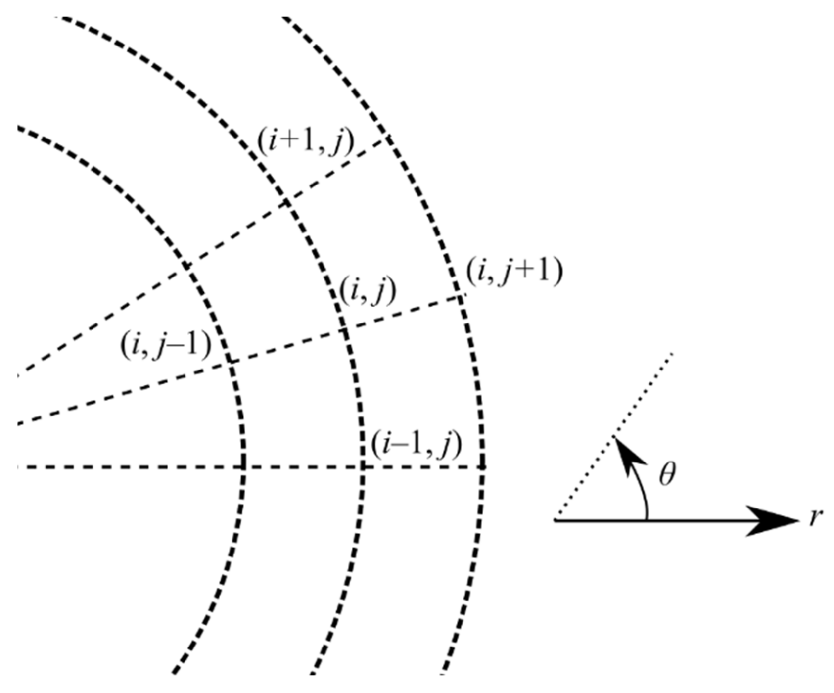
Since it is not straightforward to differentiate Equation (13), applying a simple finite differencing method can obtain the velocity vector. The discretised equations for Equations (14) and (15) are shown in Equations (16) and (17), respectively. The subscript i and j in Equations (16) and (17) represents the spatial coordinate at the θ and r component, respectively. The discretisation stencil for these notations is shown in Figure 2. Note that if the size of the stream function matrix is nx × ny, then the velocity vector matrix is reduced to (nx − 1) × (ny − 1).
u r i , j = 1 r i , j ψ i + 1 , j ψ i , j θ i + 1 , j θ i , j
u θ i , j = ψ i , j + 1 ψ i , j r i , j + 1 r i , j
The velocity potential for the flow ϕ can be obtained by solving either one of the equations as seen in Equations (18) and (19).
ϕ = r 1 r 2 u r d r
ϕ = θ 1 θ 2 r u θ d θ
Perhaps, there are many numerical techniques to perform the integration over the velocity vector [42,43] as seen in Equation (18) or Equation (19). However, it is more convenient to obtain the velocity potential by considering the following Equations (5)–(10)
ϕ = m 2 π α 2 ln r 2 α 1 ln r 1
in which r2 and r1 can be expressed as a function of r and θ according to the trigonometric rule:
r 1 = a 1 2 + r 2 2 a 1 r cos π θ
r 2 = a 2 2 + r 2 2 a 2 r cos θ
Cylindrical coordinate (r,θ) can be applied as the input before transforming them to Cartesian coordinates (x,y) using Equations (23) and (24).
x = r cos θ
y = r sin θ
MATLAB R2021a was used to code and visualise the flow. Operation is thus required to transform the velocity vector from cylindrical coordinate to Cartesian coordination. The transformation for ux and uy can be obtained by applying Equations (25) and (26), respectively.
u x = u θ cos π 2 + θ + u r cos θ
u y = u θ sin π 2 θ + u r sin θ
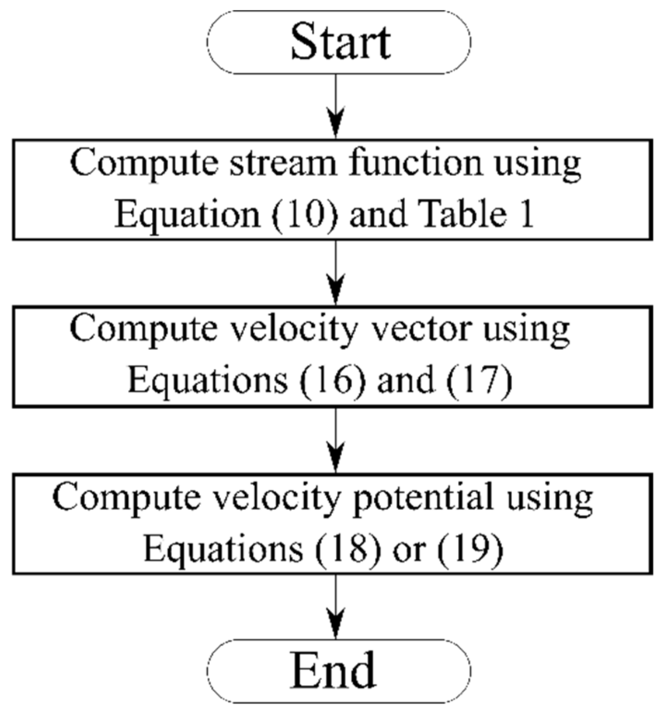
In short, in this semi-analytical method for unsymmetrical doublet flow, an analytical approach was used to obtain the stream function while the numerical finite difference method to compute velocity vector and velocity potential. The complete algorithm for the semi-numerical analysis of unsymmetrical doublet flow can be demonstrated in Figure 3.

3. Flow Structure of Unsymmetrical Doublet Flows

When the source and sink have a similar strength, a symmetrical doublet or Rankine oval structure can be formed. In the case where the source and sink have varied strengths, the resulting flow structure would be more complicated. A more complex potential flow structure could be generated based on the semi-numerical scheme as delineated in Section 2. This structure of the section will be arranged as follows: the potential flow structure due to pure unsymmetrical doublet flow is included in Section 3.1; the superposition of unsymmetrical doublet flow with different source far-field velocity magnitude direction will be covered in Section 3.2; while the effects of far-field flow orientation on the unsymmetrical doublet flow are discussed in Section 3.3.

3.1. Pure Unsymmetrical Doublet Flow

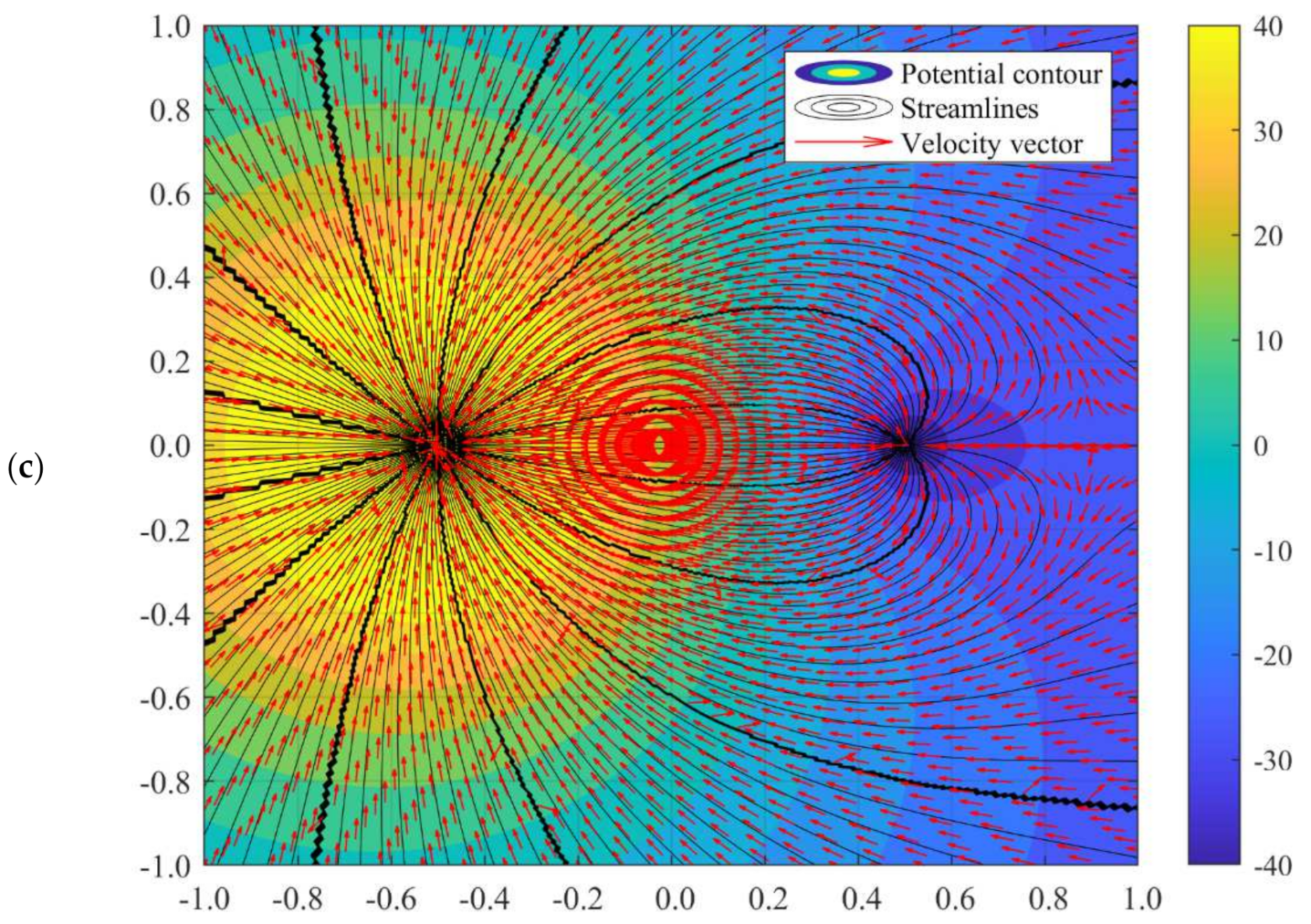
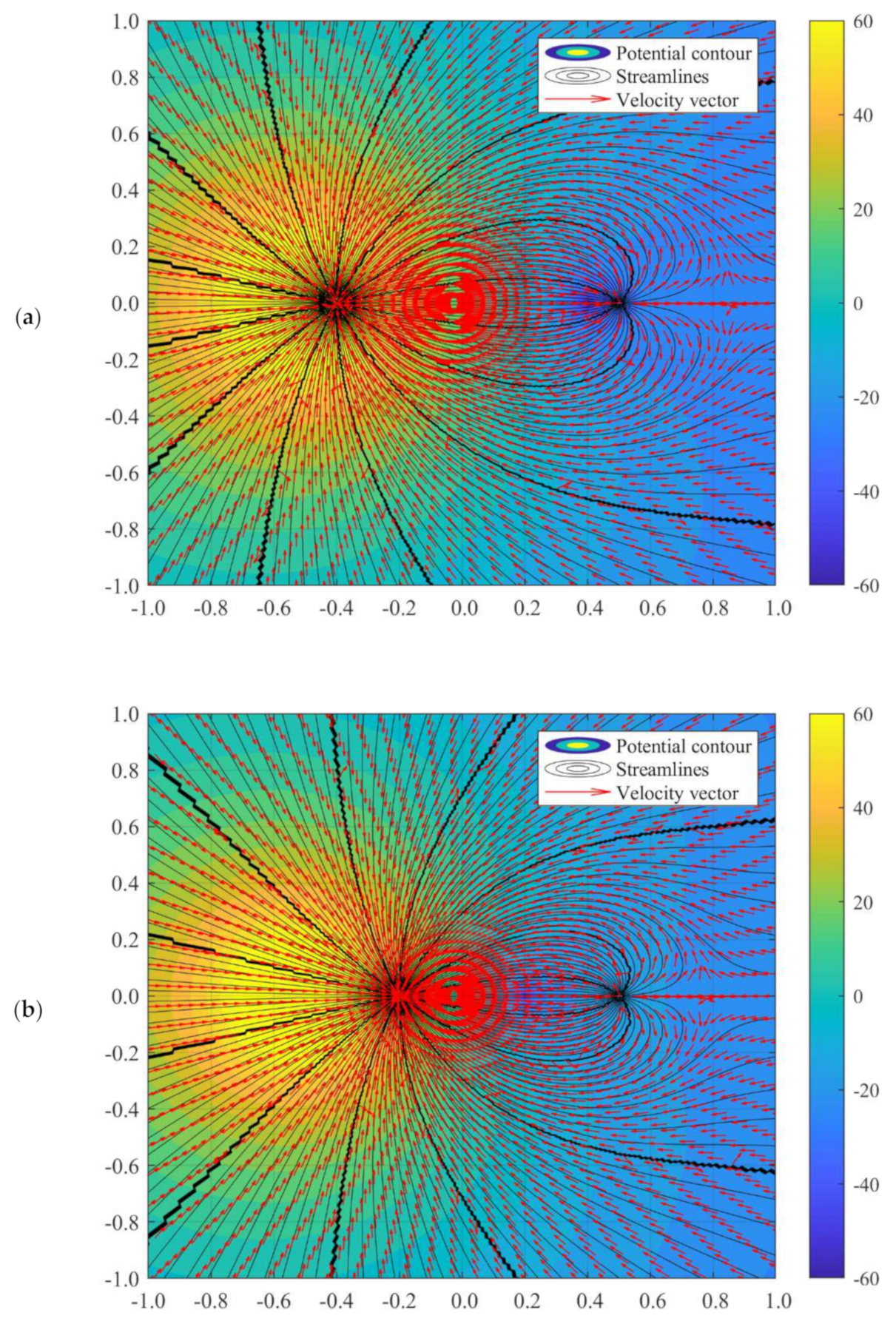
Consider a doublet flow in which the strength of the source is 2 m ^ while the value of a1 is taken as 0.5. The value m ^ is taken as 1. The example of the doublet flow solution for different strengths of sink and different values of a2 can be shown in Figure 4 and Figure 5, respectively.
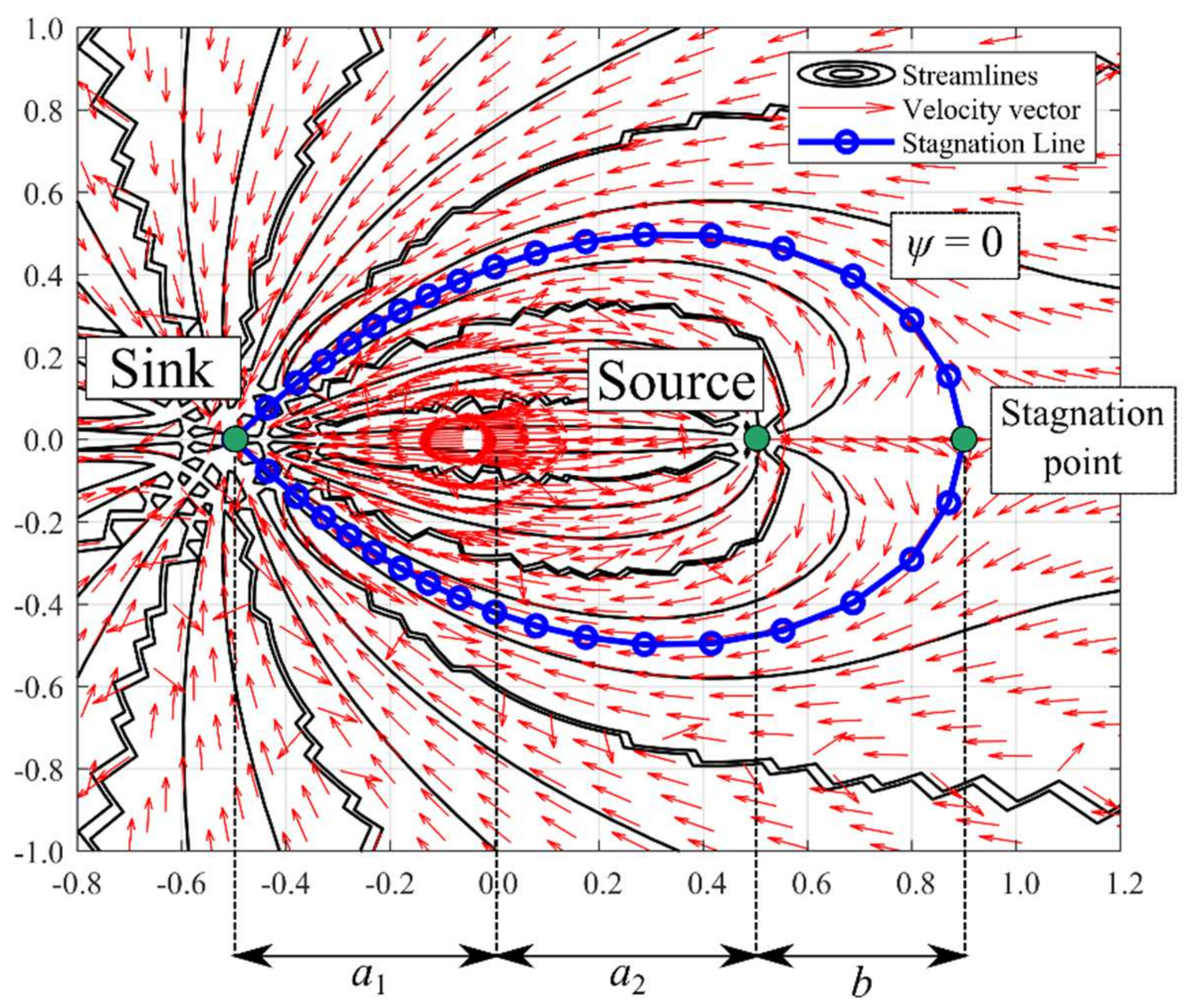
From Figure 5, it can be observed that when the strength of the sink and source is not identical, both the streamlines and potential lines are distorted. The more significant the difference between the sink and source, the more apparent the distortion is. When the strength of the sink is 3 m ^ , the flow pattern is almost similar to the doublet flow with identical source/sink strength. However, when the strength of the sink increased, the deviation of velocity field could be observed, in which the velocity vector was altered with a stiffer angle moving towards the sink. It is an interesting phenomenon that a stagnation point can be observed at a larger sink strength, i.e., 5 m ^ . This stagnation point exists as the sink with superior strength could act as a “uniform flow” moving towards the sink, countering the flow from the source. The distance of the stagnation point (see Figure 5), b, can be predicted by equating the velocity for source and sink such that:
u r , source = u r , sin k α 1 m 2 π a 1 + a 2 + b = α 2 m 2 π b b = α 2 a 1 + a 2 α 1 α 2
It shall be noted that the stagnation point could not be observed if the strength of the source was larger than the strength of the sink. The streamlines along the stagnation point can be further obtained by substituting r = b and θ = 0 into Equations (11) and (12) before computing the streamlines based on the algorithm as demonstrated in Figure 3. In other words, at the stagnation line, ψ = 0. Equating Equation (10) with zero, numerical solutions such as the fixed-point iteration technique could be deployed to obtain the value of r along with the stagnation point. The general stagnation line equation can be expressed as in Equation (28). Solving Equation (28) will obtain the stagnation line as shown in Figure 5 by taking the source and sink strength as 2 m ^ and 7 m ^ , respectively.
tan α 1 θ 1 = tan α 2 θ 2
Nonetheless, it is not straightforward to solve Equation (28). Since ψ = 0 appears in several locations in the potential flow domain, a unique solution is not available. Therefore, the graphical method is required to solve Equation (28). The initial guess for executing the graphical method is critical for the case where the strength of the source and sink is 2 m ^ and 7 m ^ , respectively. For this example, the initial guess for radius ranges from 0.3 to 0.5. Upon obtaining the equation via the graphical method, it is possible to apply interpolation techniques to get a smooth curve for the stagnation line. In the current paper, the moving least squares (MLS) method [44] is applied. The formulation of the MLS method can be found in the work of Cheah and Tey [45] while a recent review of the mathematical tool can be referred to the work of Tey et al. [46]. By taking the data generated using the graphical method, the stagnation line equation can be written as in Equation (29). The coefficient of determination R2 of Equation (29) is 0.9857, which is considered well fitted with the computed value. Of course, the stagnation line equation is only valid for the case with the strength of the source and sink as 2 m ^ and 7 m ^ , respectively, while both a1 and a2 are 0.5. The aerofoil-like equation shall be re-computed if there is any change in the potential flow variables.
y = 0.4109 + 0.5896 x 0.6541 x 2 0.4412 x 3 0 θ π 0.4109 0.5896 x + 0.6541 x 2 + 0.4412 x 3 π θ 2 π
The potential flow profile would be varied due to the distance of a1 and a2. The flow fields when a2 = 0.5 while a1 = 0.4 and 0.2 can be illustrated as in Figure 6. Perhaps, there is no difference in flow characteristics between the doublet flow of different a1 and a2 values with identical a1 and a2 values, as long as the summation of a1 and a2 is the same. For instance, the value of b remains unchanged when a2 = 0.5 and a1 = 0.2, and when a1 = 0.35 and a2 = 0.35, in accordance with Equation (27). Nonetheless, manipulating the value of a1 and a2 is beneficial in setting up the precise location of the sink and source. This advantage would assist in simulation doublet flow-related studies such as geothermal creeping flow and other environmental Darcy flow.

3.2. Superposition of Unsymmetrical Doublet Flow with Far-Field Flow

Due to the complexity of the flow vector when the far-field velocity is superimposed into the doublet flow, the formulation of the stagnation line and determination of the stagnation point is not as straightforward as discussed in the previous section. However, with the implementation of the semi-numerical algorithm, the complex potential flow can be visualised in few simple steps. The interference of free-stream flow with the equal-strength doublet flow could form a Rankine oval flow structure, well documented in many fluid mechanics references [2,42,47,48]. In comparison, the involvement of varied-strength doublet flow would produce many interesting flow phenomena. The following subsections will discuss the alteration of Rankine oval structures due to sink-dominant doublet, source-dominant doublet, and the orientation of far-field velocity.

3.2.1. Sink-Dominant Superposed Flow

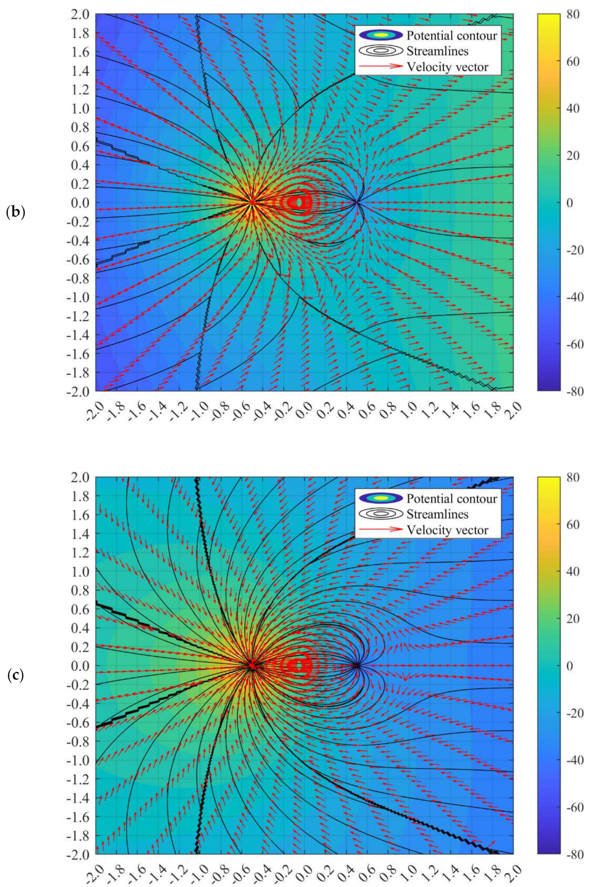
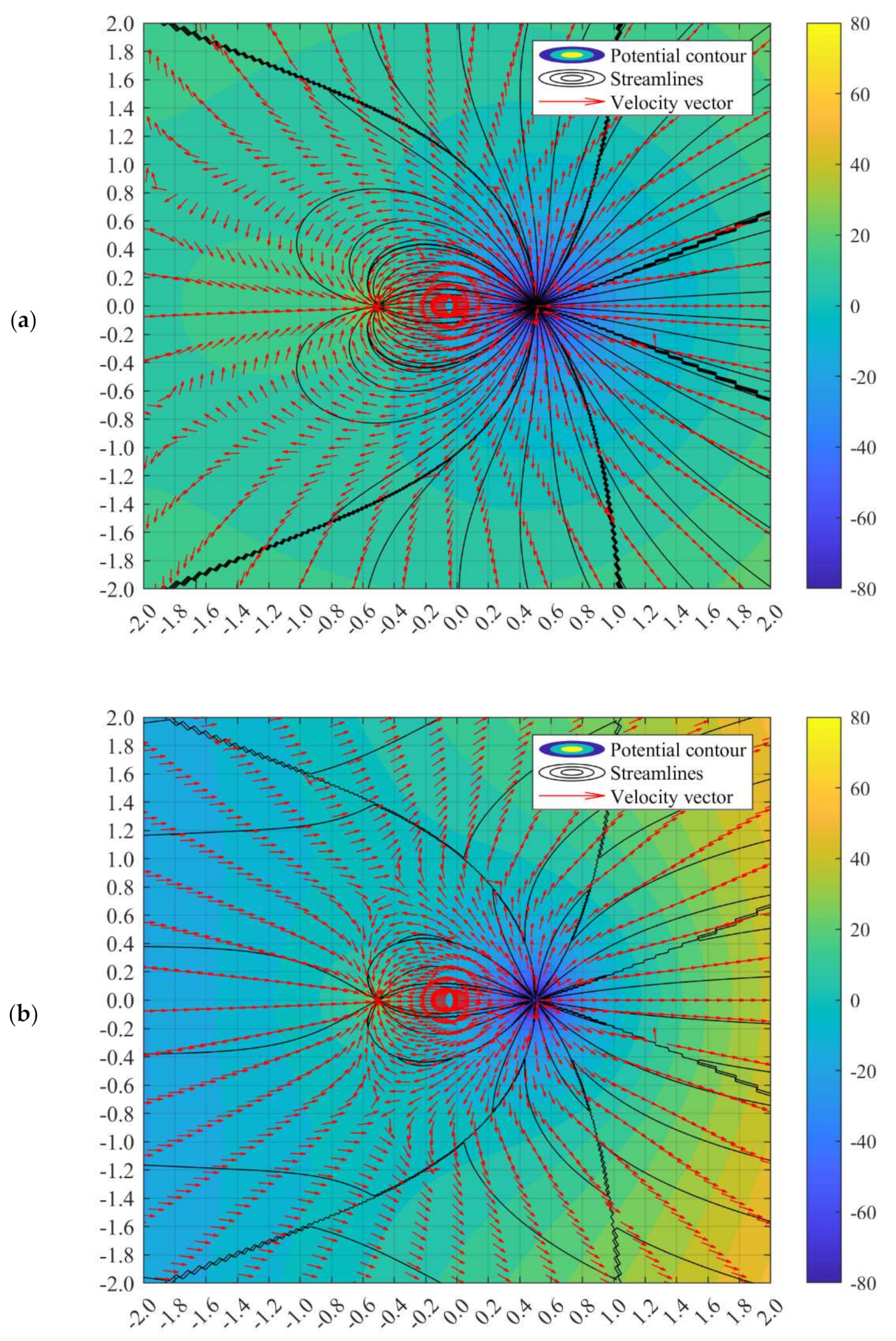
The superposition of free-stream or far-field velocity on the doublet flow is modelled. The interference of two potential flows leads to different types of interesting flow structures. When the sink and source strength is identical (i.e., α1 = α2), the Rankine oval body can be obtained. Nonetheless, when α1α2, the Rankine oval structure does not necessarily appear, depending on the magnitude and direction of the far-field velocity. Some examples of superposition of far-field velocity on the sink-dominated doublet flow are simulated in Figure 7.
For the case in which the strength of the sink is larger than the source, if the incoming far-field flow originates from the sink-sided direction as shown in Figure 7a, there will be no Rankine oval structure formed. However, the far-field velocity could impose a significant impact on the location of the stagnation point. From the observation of Figure 7a,b, a stronger far-field velocity would extend the value of b. The location of the stagnation point can be determined by summating the velocity components to be zero. Therefore, the value of b for this case can be written as in Equation (30).
2 π U b 2 + m 2 m 1 + 2 π U a 1 + a 2 b + m 2 a 1 + a 2 = 0
Perhaps, Equation (30) is only valid for an exceedingly small range of values such that:
U m 1 2 π a 1 + a 2 + b m 2 2 π b
When the far-field velocity is too strong, the stagnation point will not exist at the wake of the co-linear line of the source because the free stream flow will overwhelm the suction velocity of the sink. Instead, there will be two turning points deviated symmetrically from the co-linear line of the source. This phenomenon is due to the strong far-field velocity that bolsters the outward velocity from the source to the wake of the co-linear line of the source, negating the possibility of having any zero-velocity location along this line. From Figure 7b, the turning points can be observed at the location approximated at (−0.5, 0.8) and (−0.5, −0.8). The streamline which connects the turning points, sink, and source would bind the altered Rankine oval structure. This streamline is termed as aerodynamic line in this paper.
When the far-field velocity is superimposed from the source-sided direction, a stagnation point is formed as well, yet with a smaller value of b compared with the pure doublet flow, as demonstrated in Figure 7c. When the far-field velocity strengthens, the stagnation point will remain along the wake of the co-linear line of the source.
The value of b for such a case can be described as in Equation (32), which is valid only for the range of far-field velocities as shown in Equation (33).
2 π U b 2 + m 1 m 2 + 2 π a 1 + a 2 U b m 2 a 1 + a 2 = 0
U m 2 2 π b m 1 2 π a 1 + a 2 + b
Moreover, it is noteworthy that at an extremely high far-field velocity from the source-sided direction, a secondary stagnation point can be observed at the wake of the sink. For instance, in Figure 7d, the secondary stagnation point is located approximately (−1.7, 0). The flow structure resembles the half-body flow. In the half-body flow, the stagnation line forms due to the intersection between the far-field flow and the source. In the current case, the current half-body flow forms from the imposition of significantly powerful far-field velocity and sink-dominated doublet flow. The greater the far-field speed from the source-sided direction, the larger the distance between the secondary stagnation point and the sink.
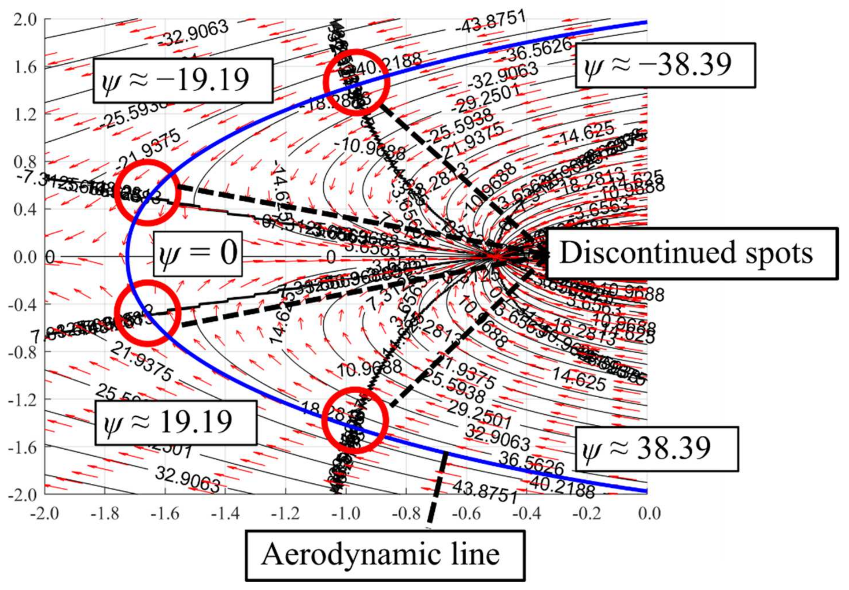
The continuity of the stagnation line (ψ = 0) is broken due to the discontinued spot, as shown in Figure 8. The discontinued spot is formed due to the dominance of the sink, which deviates and realigns the streamlines around the sink’s domain. However, it is still possible to obtain the aerodynamic line that forms a flow structure that resembles Rankine-oval or half body structure. It is not straightforward to determine the aerodynamic line for the sink-dominant superposed flow as there is a discontinued stream function along the stagnation line. For example, in Figure 7d, at 163° ≤ θ ≤ 180°, a non-zero stream function can be observed (see Figure 8 for a detailed illustration). The point which separates the zero and non-zero stagnation stream function is named as the discontinued point in this paper. Thus, the first pair of discontinued points can be observed at (0.5, −1.65) and (−0.5, −1.65), in which the stagnation stream function changes from ψ = 0 to ψ ≈ ±19.19. Meanwhile, at 124° ≤ θ ≤ 163°, the stagnation stream function changes again from ψ ≈ ±19.19 to ψ ≈ ±38.39, in which the discontinued spots are located approximately at (1.4, −0.95) and (−1.4, −0.95). Due to this complication raised by the discontinued spots, the aerodynamic line can only be approximated with graphical visualisation.

3.2.2. Source-Dominant Superposed Flow

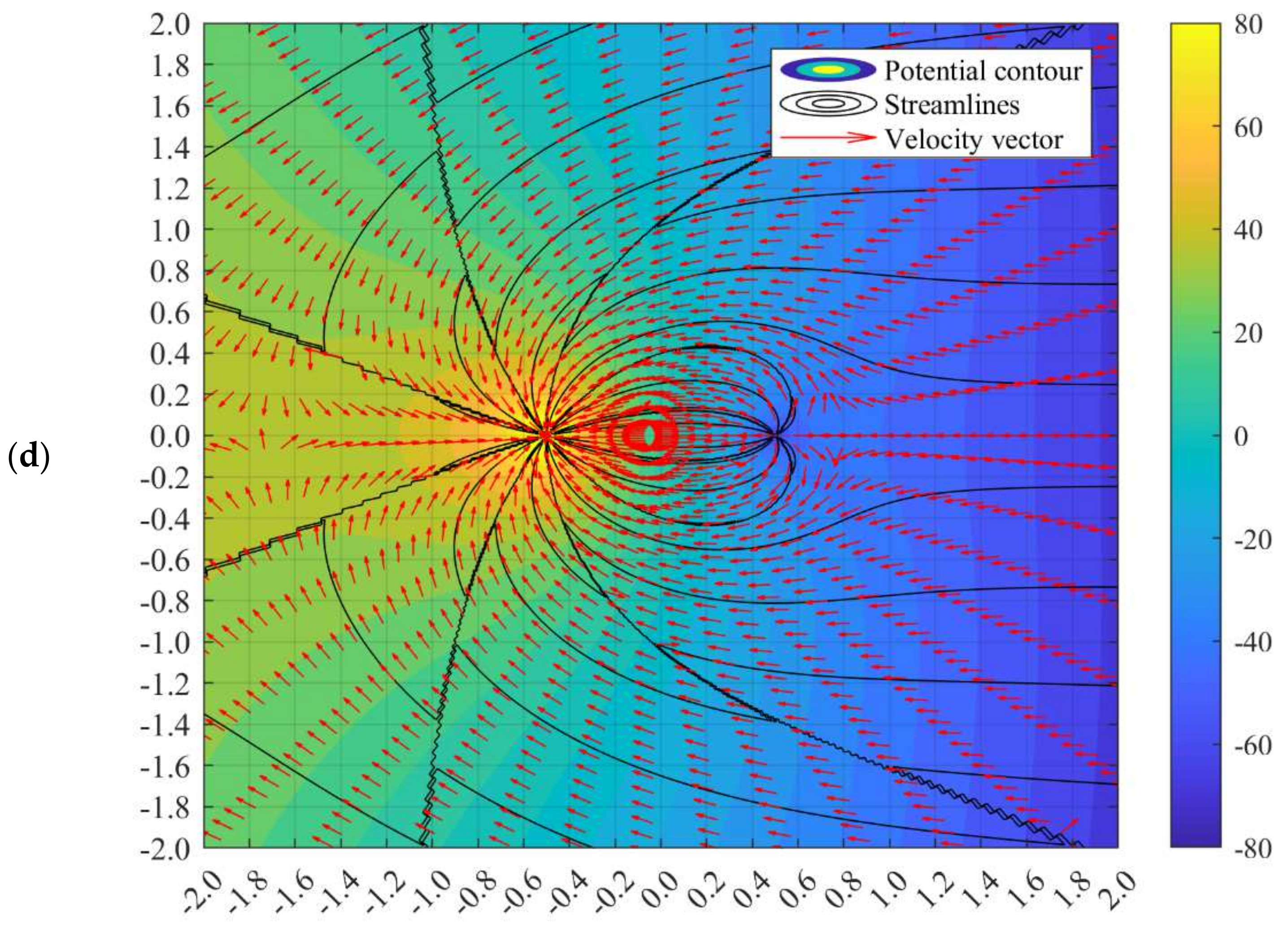
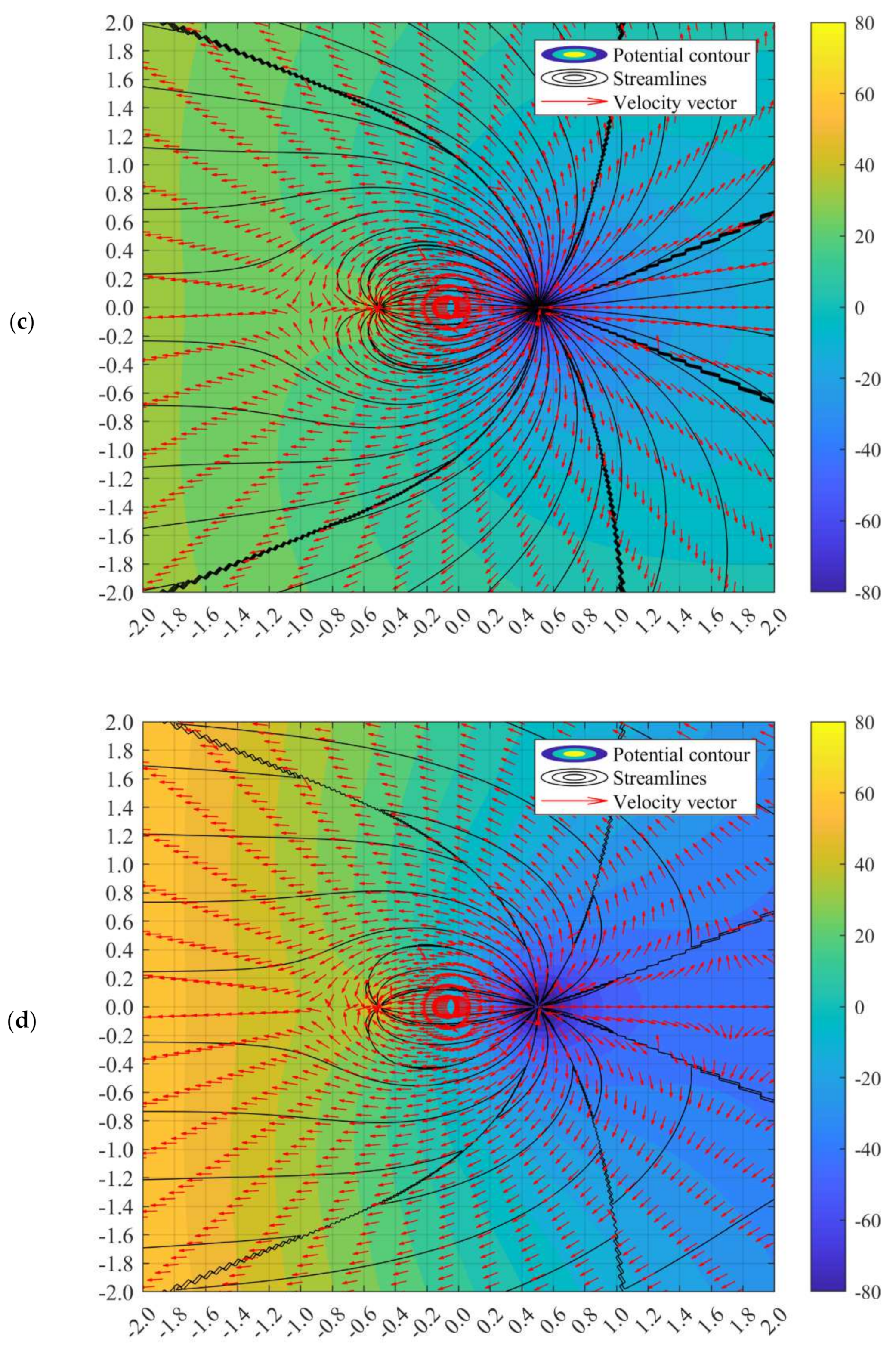
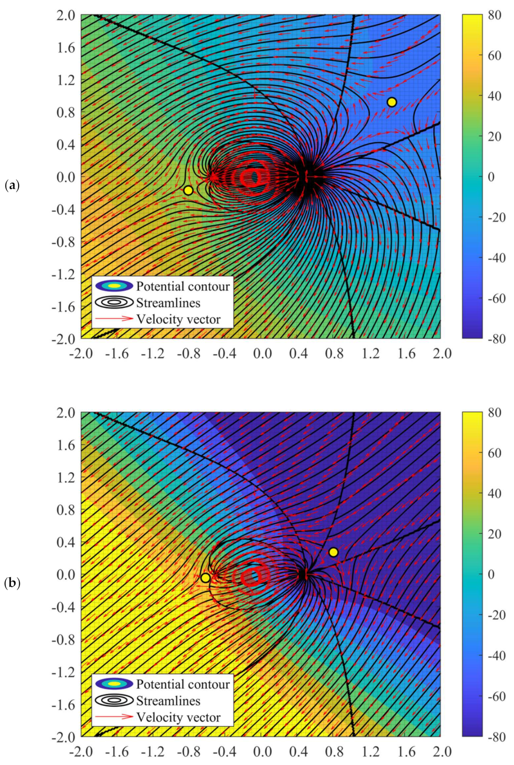
Due to the superposition of source-dominant doublet flow and far-field flow, the altered flow structure appears to be symmetrical to the sink-dominant superposed flow, as discussed in the previous section. Due to the strong source, the stagnation points are shifted leftward in locations nearer to the sink, as illustrated in Figure 9a–d. The location of the stagnation point can also be determined by equating the velocity components to be zero. The value of b for the sink-sided and source-sided far-field can be shown in Equations (30) and (32), respectively. The equations are only valid for a small range of far-field velocity.
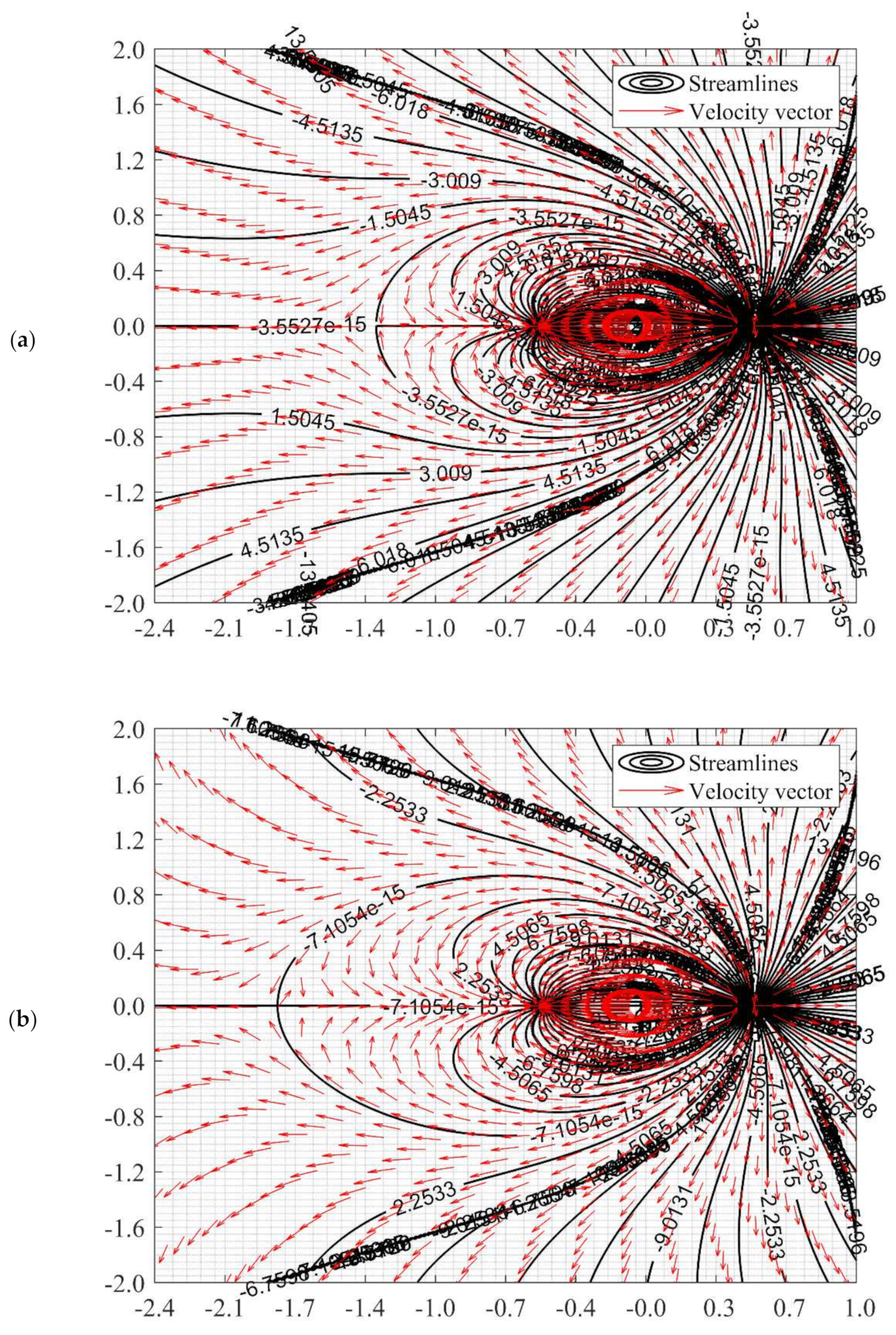
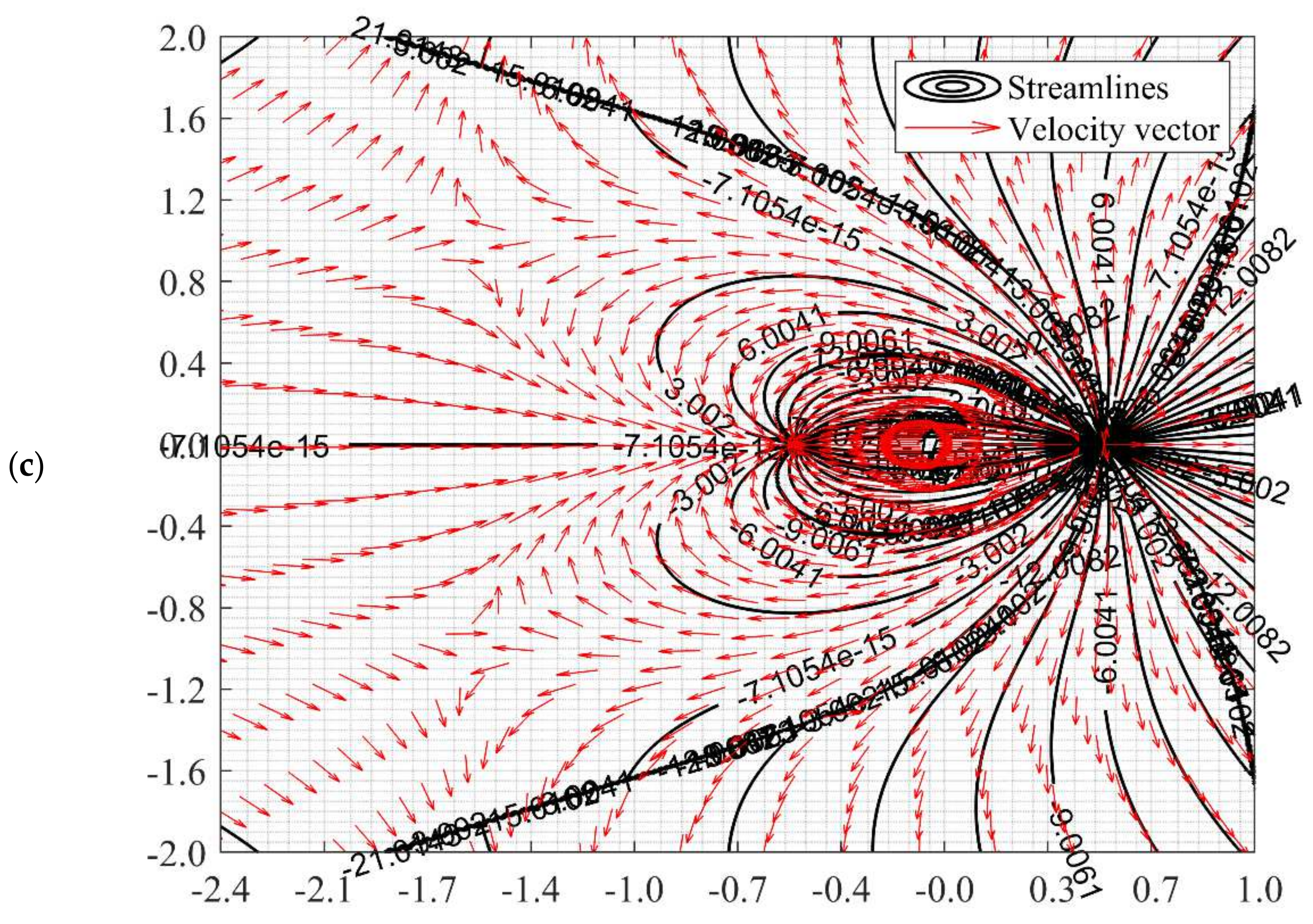
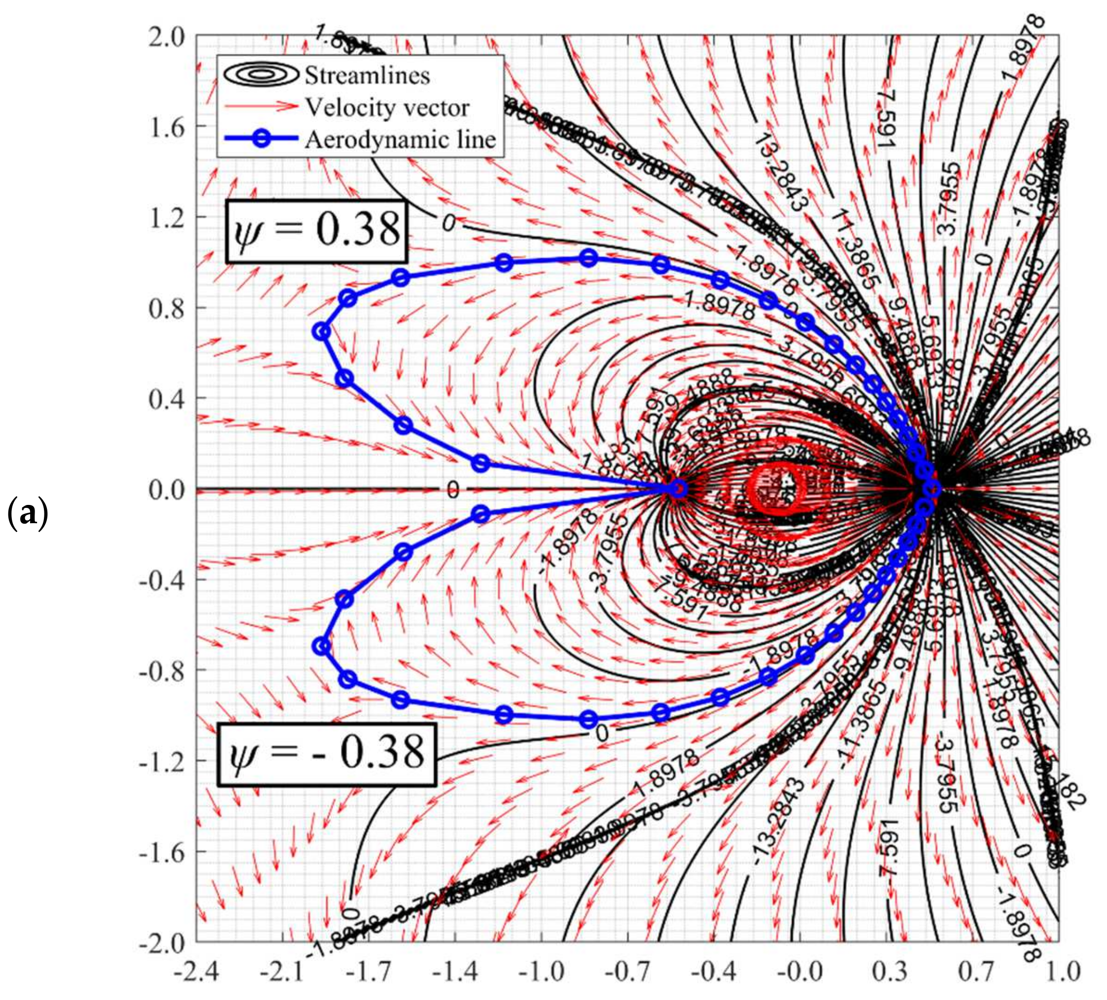
However, when the far-field velocity is beyond the range as stipulated in Equations (31) and (33), with increasing far-field velocity, the stagnation point and stagnation line will gradually grow further and larger before disappearing. The streamline evolution due to the increasing far-field velocity can be referred to in Figure 10. At a low far-field velocity where the stagnation point exists, the stagnation line can be obtained at ψ = 0. A detailed graphical method is required to approximate the aerodynamic line that bounds the doublet domain at a higher far-field velocity where the stagnation point has perished. The graphical numerical approach is required as the value of the aerodynamic line stream function could be non-zero, and the value of the stream function has to be approximated under a high-resolution stream function plot. For example, the stream function of the aerodynamic line of Figure 9a,b is about ±0.38 and ±14.8, respectively. With the graphical method as delineated in Section 3.1, the coordinates of the stagnation line of Figure 9a,b can be plotted as Figure 11.
Therefore, it can be seen that when the far-field velocity grows more robust, the stagnation line will be broken to form the aerodynamic line. The aerodynamic convex will additionally become flatter as the far-field velocity continues to grow stronger. As such, at U → ∞ the aerodynamic line will deform as a concave structure.
Finally, the secondary stagnation/aerodynamic point will be relocated in proximity with the source when an extremely high far-field velocity from the source-sided direction is applied, as shown in Figure 9d. The visualisation of the secondary aerodynamic line will be slightly troublesome compared with the normal stagnation line due to stagnation spots.

3.3. Effects of Far-Field Flow Orientation on Unsymmetrical Doublet Flow

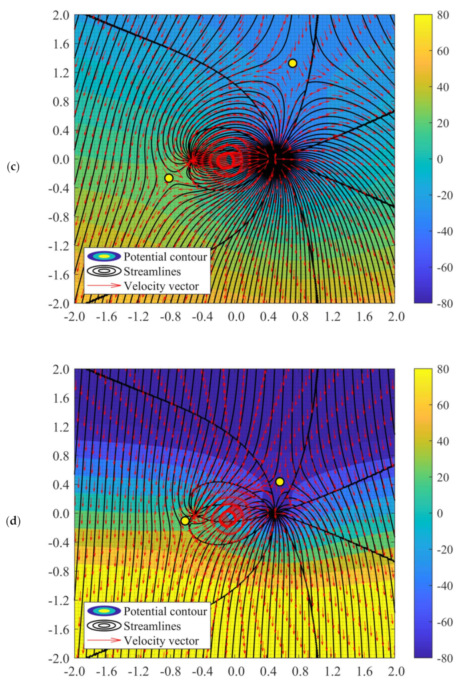
The flow structure formed due to different far-field flow orientations could be referred to in Figure 12. When the far-field flow direction changes, the altered Rankine oval structure will be broken down easily. By taking U = 20 m ^ at source-dominant superposed flow as the example, when the uniform flow direction is parallel with the sink-source orientation (as in Section 3.1 and Section 3.2), the primary stagnation point (stagnation point originating from the source) and the secondary stagnation point (stagnation point originating from the sink) will lie within a straight line. When the uniform flow comes with an angle of θ = 45°, the primary and secondary stagnation point will deviate upwards and downwards, respectively.
When the flow angle is changed to θ = 90°, the line of stagnation points remains distorted. This phenomenon could be deemed a unique flow structure for sink- or source-dominated doublet flow as, in the flow with equally strong sink-source flow, the stagnation points will fall on the same line. A detailed discussion on this matter has been disclosed in the work of Weijermars and van Harmelen [41]. Even when θ = 90°, the line of stagnation points does not form a straight line.
When the far-field velocity increases, the distance between the stagnation points from the sink/source decreases. This reduction implies that the area of the doublet flow boundary has shrunk, and more fluids discharged from the source (or injector) will deviate away from the sink (or producer). Furthermore, when the far-field speed at θ = 90° and 135° is too large, no fluid from the injector will be flown to the producer. It happens as the boundary of doublet is broken, and no recirculation from the source to sink can be observed. The fluid will be forced away to the far-field shortly after it is discharged from the source. This observation is essential in the future innovative design of geothermal devices and hydrocarbon reservoirs. A proper alignment of sink-source orientation in response to far-field flow direction could avoid undesirable producer loss and greatly influence the sweep efficiency.

4. Potential Aerodynamic Applications of Unsymmetrical Doublet Flows

The current work provides a deeper insight into the flow structure on the effect of unbalanced sink-source strength. It could be beneficial in the innovative applications of groundwater creep flow predictions, geothermal well placement, and other environmental flows in the future. For instance, there is potential to utilise the unbalanced sink-source potential flow for better fluidic mixing efficiency [29] due to the existence of discontinued spots (see Figure 8), which promote micro-turbulence [49].
Besides the works mentioned above, the general doublet flow visualisation could also provide a new revelation about its potential applications in bio-inspired aerodynamic design and manipulation. Intensive research has been done in the design and operation of bio-inspired unmanned vehicles. However, to the authors’ knowledge, all geometry of the unmanned vehicles was determined either by mathematical models, by coordinate scanning from the animals’ specimen, or a combination of both. To name a few, the Fourier series function was applied by Aono et al. [50] to model the 3D kinematics of wings for insect flight, while a high-speed camera was used by Meng et al. [51] to capture the aerodynamic shape of fruit flies. An integration of both mathematical models and experimental observations was reported by Liu [52], where the effect of wing flexibility on insect aerodynamics was investigated. Similar works were also reported by Zimmerman and Abdelkefi [53], Scaradozzi et al. [54], Bian and Xiang [55], Salazar et al. [56], and Hudson et al. [57].
Cilia and flagella were found to be able to generate doublet flow around their oscillatory bodies, which would generate stresses for bending mechanisms and propulsion [58]. Frumkin et al. [59] conducted an experiment to observe the swimming mechanism and found that the formation of doublet flow is indispensable to interfacial dynamics for hydrodynamic propulsion. However, research by Klindt and Friedrich [60] further showed that microswimmers attempted to minimise the generation of doublet flow structure to reduce hydrodynamic dissipation which predators could be able to detect. This feature could be applied to reduce aerodynamic noise produced by bioinspired unmanned vehicles while optimising propulsion efficiency. Despite extensive research in the geometry of bioinspired vehicles, there remains a paucity of literature that have reported on the relations between potential flow and animal morphology.
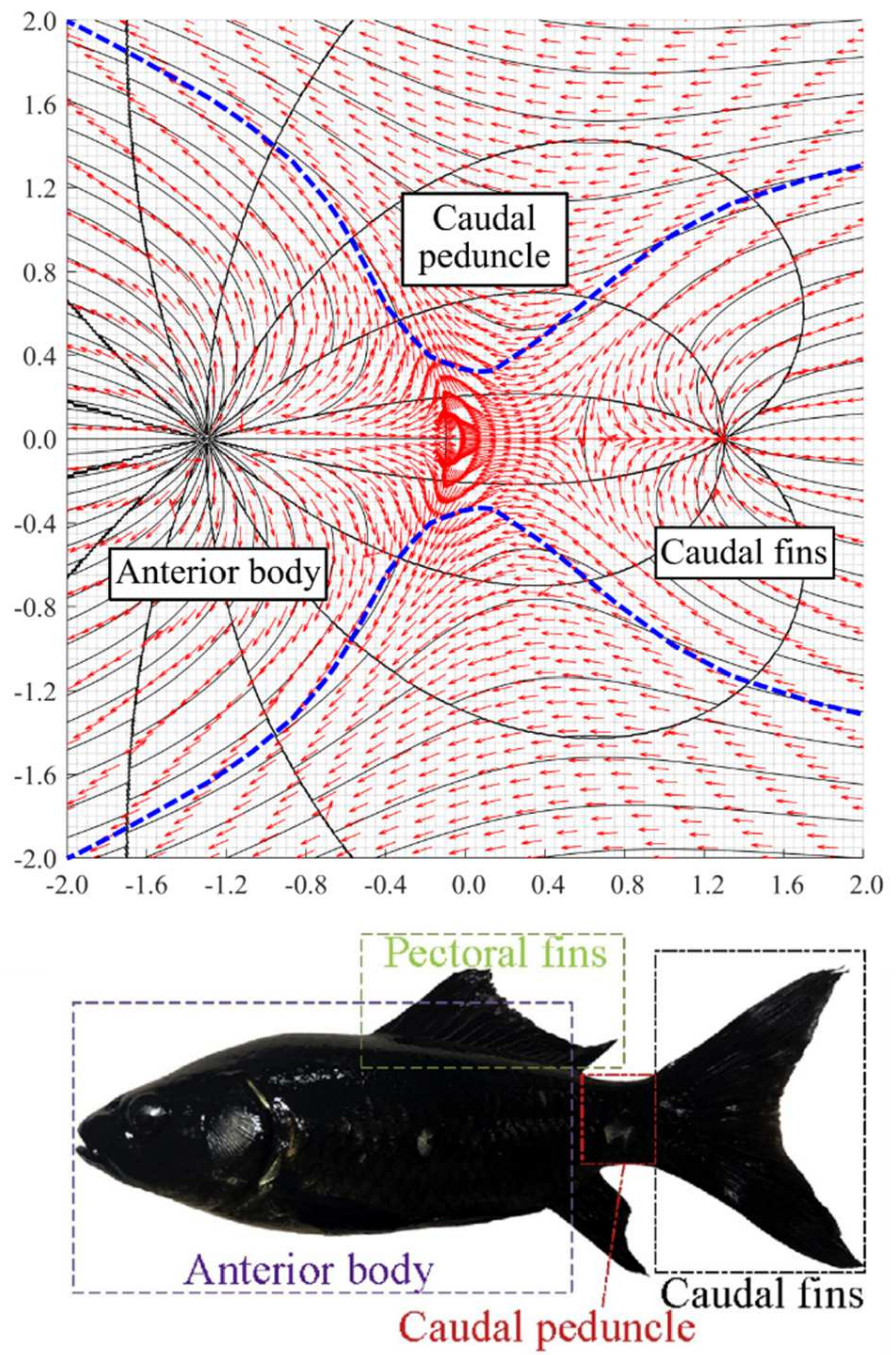
It is possible to relate the potential flow of doublet boundaries with the 3D morphological structure of animals, which would assist the future design in unmanned aerial/underwater vehicles. For example, by taking a1 = a2 = 1.3, while the strength of the source and sink is 2 m ^ and 7 m ^ , respectively, at U = 50 m ^ and θ = 180°, an aerodynamic line resembling a Carangiform swimmer’s caudal peduncle [54,61] could be formed, as illustrated in Figure 13. The source and sink can be perceived as the centre of the rear of the anterior body and caudal fin, respectively. With the user-defined parameters as aforementioned, the aerodynamic line which connects the anterior body and caudal fin can be formed. Then, with some interpolation tools such as the moving least squares method, the geometry of the aerodynamic line can be obtained. A geometry built upon the aerodynamic line could theoretically ensure a smooth flow and thus improve swimming efficiency.
Moreover, the methodology explained in the current work shows potential for application in many other bio-inspired structures such as dolphins [62], eels [63], fruit flies [51], ladybirds [64], and damselflies [65], to name a few. Since the far-field speed and orientation greatly influence the aerodynamic/stagnation line, the line’s deformation could optimise the structure’s ability to withstand the surrounding flow conditions.

5. Conclusions and Recommendation

A semi-numerical scheme has been proposed to analyse and visualise the general doublet flow, which encompasses the unbalanced strength of sink and source. Both pure and superposed doublet flow are investigated. Compared with the flow structure formed by the balanced sink and source strength, the unsymmetrical doublet flow could exhibit various types of stagnation/aerodynamic lines, depending on the strength of source/sink, far-field velocity, and far-field orientation. The conclusion is summarised as below:
  • Doublet boundary would be distorted to form convex (due to low far-field velocity), concave (due to high far-field velocity), and other interesting shapes (in what condition).
  • The conceptual study provides deeper insight into the flow structure of the effect of unbalanced sink-source strength.
  • The research output potentially to apply in innovative environmental flow design and renders an alternative to formulate an aerodynamic curve for the design of bio-inspired structures in the near future.
The proposed algorithm is straightforward to be applied to generate various unsymmetrical doublet flow structures without the necessity to visualise the flow using complicated numerical schemes. However, it shall be noted that the formulation applies only to the case where the ratio between the strength of source and sink appears as an integer. More research works shall be done in the future to address the unsymmetrical doublet flow whenever any real number involves.

Author Contributions

W.Y.T.—Conceptualisation, methodology, writing—original draft; W.H.L.—conceptualisation, writing—review and editing; K.H.T.—resources, funding acquisition, validation, writing—original draft; K.Y.W.—investigation, writing—review and editing. All authors have read and agreed to the published version of the manuscript.

Funding

This research was funded by UCSI University with grant number REIG-FETBE-2021/039 and The APC was funded by REIG-FETBE-2021/013.

Informed Consent Statement

Not applicable.

Conflicts of Interest

The authors declare no conflict of interest.

Nomenclature

SymbolDescription
ϕVelocity potential
ψStream function
mStrength of source/sink
rDistance from source/sink to arbitrary point within the problem domain
uVelocity

References

  1. Bruce, R.M.; Donald, F.Y.; Theodore, H.O. Fundamentals of Fluid Mechanics, 5th ed.; John Wiley & Sons (Asia) Pte Ltd.: Singapore, 2006. [Google Scholar]
  2. Holzbecher, E. Potential Flow. In Encyclopedia of Water; Wiley: Hoboken, NJ, USA, 2019; pp. 1–10. [Google Scholar]
  3. Katopodes, N.D. Ideal Fluid Flow. In Free-Surface Flow; Elsevier: Amsterdam, The Netherlands, 2019; pp. 428–515. [Google Scholar]
  4. Jiang, T.; Zhang, J.; Wan, W.; Cui, S.; Deng, D. 3D transient numerical flow simulation of groundwater bypass seepage at the dam site of Dongzhuang hydro-junction. Eng. Geol. 2017, 231, 176–189. [Google Scholar] [CrossRef]
  5. Mategaonkar, M. Simulation of groundwater flow using meshfree collocation method with Cubic Spline function. Groundw. Sustain. Dev. 2021, 13, 100579. [Google Scholar] [CrossRef]
  6. Seyedpour, S.; Kirmizakis, P.; Brennan, P.; Doherty, R.; Ricken, T. Optimal remediation design and simulation of groundwater flow coupled to contaminant transport using genetic algorithm and radial point collocation method (RPCM). Sci. Total Environ. 2019, 669, 389–399. [Google Scholar] [CrossRef] [PubMed] [Green Version]
  7. Park, Y.-J.; Hwang, H.-T.; Suzuki, S.; Saegusa, H.; Nojiri, K.; Tanaka, T.; Bruines, P.; Abumi, K.; Morita, Y.; Illman, W. Improving precision in regional scale numerical simulations of groundwater flow into underground openings. Eng. Geol. 2020, 274, 105727. [Google Scholar] [CrossRef]
  8. Xie, Y.; Wu, J.; Nan, T.; Xue, Y.; Xie, C.; Ji, H. Efficient triple-grid multiscale finite element method for 3D groundwater flow simulation in heterogeneous porous media. J. Hydrol. 2017, 546, 503–514. [Google Scholar] [CrossRef]
  9. Xia, C.-A.; Pasetto, D.; Hu, B.X.; Putti, M.; Guadagnini, A. Integration of moment equations in a reduced-order modeling strategy for Monte Carlo simulations of groundwater flow. J. Hydrol. 2020, 590, 125257. [Google Scholar] [CrossRef]
  10. Pathania, T.; Eldho, T.; Bottacin-Busolin, A. Coupled simulation of groundwater flow and multispecies reactive transport in an unconfined aquifer using the element-free Galerkin method. Eng. Anal. Bound. Elem. 2020, 121, 31–49. [Google Scholar] [CrossRef]
  11. Swathi, B.; Eldho, T. Groundwater flow simulation in unconfined aquifers using meshless local Petrov–Galerkin method. Eng. Anal. Bound. Elem. 2014, 48, 43–52. [Google Scholar] [CrossRef]
  12. Hanssen, F.-C.W.; Greco, M. A potential flow method combining immersed boundaries and overlapping grids: Formulation, validation and verification. Ocean Eng. 2021, 227, 108841. [Google Scholar] [CrossRef]
  13. Anderson, E.I. An analytical solution representing groundwater-surface water interaction. Water Resour. Res. 2003, 39, 1071. [Google Scholar] [CrossRef]
  14. Wang, C.; Mu, X.; He, Y.; Li, D.; Shi, Y. A novel potential flow model for granular flow in two-dimensional flat-bottomed packed bed with centric discharge. Powder Technol. 2019, 342, 545–554. [Google Scholar] [CrossRef]
  15. Bakker, M.; Miller, A.D.; Morgan, L.; Werner, A. Evaluation of analytic solutions for steady interface flow where the aquifer extends below the sea. J. Hydrol. 2017, 551, 660–664. [Google Scholar] [CrossRef]
  16. Liu, W.-Q.; Xiong, L.-N.; Zhang, G.-W.; Yang, M.; Wu, W.-G.; Song, X.-M. Research on Hydroelastic Response of an FMRC Hexagon Enclosed Platform. Symmetry 2021, 13, 1110. [Google Scholar] [CrossRef]
  17. Magdalena, I.; Firdaus, K. Numerical Study for Unsteady Waves Generated by Flow over a Permeable Wavy Bed. Fluids 2021, 7, 9. [Google Scholar] [CrossRef]
  18. Chen, Z.-M.; Price, W.G. Dissipative free-surface solver for potential flow around hydrofoil distributed with doublets. Appl. Math. Mech. 2012, 33, 1467–1480. [Google Scholar] [CrossRef]
  19. Frayssinhes, R.; Girardon, S.; Denaud, L.; Collet, R. Modeling the Influence of Knots on Douglas-Fir Veneer Fiber Orientation. Fibers 2020, 8, 54. [Google Scholar] [CrossRef]
  20. Sahin, I.; Hyman, M. Numerical calculation for the flow of submerged bodies under a free surface. Ocean Eng. 1993, 20, 339–347. [Google Scholar] [CrossRef]
  21. Huggins, A.; Packwood, A. The optimum dimensions for a long-range, autonomous, deep-diving, underwater vehicle for oceanographic research. Ocean Eng. 1994, 21, 45–56. [Google Scholar] [CrossRef]
  22. Xu, Z.; Li, Q.; Gorodtsov, V. Wave drag of rapidly and horizontally moving Rankine ovoid in uniformly stratified fluid. Prog. Nat. Sci. 2008, 18, 723–727. [Google Scholar] [CrossRef]
  23. Suner, M.; Salci, S.A.; Yigit, K.S.; Kandemir, I. Analytical analysis of hydrodynamics of the perforated Rankine oval. Ocean Eng. 2015, 108, 227–240. [Google Scholar] [CrossRef]
  24. Raven, H.C. A method to correct shallow-water model tests for tank wall effects. J. Mar. Sci. Technol. 2018, 24, 437–453. [Google Scholar] [CrossRef]
  25. Roisman, I.; Yarin, A.; Rubin, M. Normal penetration of an eroding projectile into an elastic–plastic target. Int. J. Impact Eng. 2001, 25, 573–597. [Google Scholar] [CrossRef]
  26. Rubin, M.; Kositski, R.; Rosenberg, Z. Essential physics of target inertia in penetration problems missed by cavity expansion models. Int. J. Impact Eng. 2016, 98, 97–104. [Google Scholar] [CrossRef]
  27. Rubin, M. A simplified and modified model for long rod penetration based on ovoids of Rankine. Int. J. Impact Eng. 2021, 156, 103927. [Google Scholar] [CrossRef]
  28. Trivedi, C. A review on fluid structure interaction in hydraulic turbines: A focus on hydrodynamic damping. Eng. Fail. Anal. 2017, 77, 1–22. [Google Scholar] [CrossRef]
  29. Cola, B.A.; Schaffer, D.; Fisher, T.S.; Stremler, M. A Pulsed Source-Sink Fluid Mixing Device. J. Microelectromech. Syst. 2006, 15, 259–266. [Google Scholar] [CrossRef]
  30. Basu, A.S.; Gianchandani, Y.B. Microfluidic doublets in aqueous samples generated by microfabricated thermal probes. Sens. Actuators A Phys. 2010, 158, 116–120. [Google Scholar] [CrossRef]
  31. Benouaguef, I.; Musunuri, N.; Amah, E.C.; Blackmore, D.; Fischer, I.S.; Singh, P. Solutocapillary Marangoni flow induced in a waterbody by a solute source. J. Fluid Mech. 2021, 922. [Google Scholar] [CrossRef]
  32. Pinsker, F.; Berloff, N.G. Transitions and excitations in a superfluid stream passing small impurities. Phys. Rev. A 2014, 89, 053605. [Google Scholar] [CrossRef] [Green Version]
  33. Luo, F.; Xu, R.-N.; Jiang, P.-X. Numerical investigation of fluid flow and heat transfer in a doublet enhanced geothermal system with CO2 as the working fluid (CO2–EGS). Energy 2014, 64, 307–322. [Google Scholar] [CrossRef]
  34. Willems, C.; Nick, H.M.; Weltje, G.J.; Bruhn, D.F. An evaluation of interferences in heat production from low enthalpy geothermal doublets systems. Energy 2017, 135, 500–512. [Google Scholar] [CrossRef]
  35. Zhao, Z.; Dou, Z.; Liu, G.; Chen, S.; Tan, X. Equivalent flow channel model for doublets in heterogeneous porous geothermal reservoirs. Renew. Energy 2021, 172, 100–111. [Google Scholar] [CrossRef]
  36. Mahbaz, S.B.; Yaghoubi, A.; Dehghani-Sanij, A.; Sarvaramini, E.; Leonenko, Y.; Dusseault, M.B. Well-Doublets: A First-Order Assessment of Geothermal SedHeat Systems. Appl. Sci. 2021, 11, 697. [Google Scholar] [CrossRef]
  37. Kong, Y.; Pang, Z.; Shao, H.; Kolditz, O. Optimization of well-doublet placement in geothermal reservoirs using numerical simulation and economic analysis. Environ. Earth Sci. 2017, 76, 118. [Google Scholar] [CrossRef]
  38. Romanov, D.; Leiss, B. Analysis of Enhanced Geothermal System Development Scenarios for District Heating and Cooling of the Göttingen University Campus. Geosciences 2021, 11, 349. [Google Scholar] [CrossRef]
  39. Haghiabi, A.H.; Mohammadzadeh-Habili, J.; Parsaie, A. Development of an evaluation method for velocity distribution over cylindrical weirs using doublet concept. Flow Meas. Instrum. 2018, 61, 79–83. [Google Scholar] [CrossRef]
  40. Severino, G. Dispersion in doublet-type flows through highly anisotropic porous formations. J. Fluid Mech. 2021, 931. [Google Scholar] [CrossRef]
  41. Weijermars, R.; Van Harmelen, A. Breakdown of doublet recirculation and direct line drives by far-field flow in reservoirs: Implications for geothermal and hydrocarbon well placement. Geophys. J. Int. 2016, 206, 19–47. [Google Scholar] [CrossRef] [Green Version]
  42. Cengel, Y.A.; Cimbala, J.M. Fluid Mechanics: Fundamentals and Applications; McGraw Hill: New York, NY, USA, 2014; ISBN 9780073380322. [Google Scholar]
  43. Chapra, S.C.; Canale, R.P. Numerical Differentiation and Integration. In Numerical Methods for Engineers; McGraw Hill: New York, NY, USA, 2010; pp. 585–698. [Google Scholar]
  44. Lancaster, P.; Salkauskas, K. Surfaces generated by moving least squares methods. Math. Comput. 1981, 37, 141–158. [Google Scholar] [CrossRef]
  45. Cheah, C.K.; Tey, W.Y. Construction on Morphology of Aquatic Animals via Moving Least Squares Method. J. Phys. Conf. Ser. 2020, 1489, 012014. [Google Scholar] [CrossRef]
  46. Tey, W.Y.; Sidik, N.A.C.; Asako, Y.; Muhieldeen, M.W.; Afshar, O. Moving Least Squares Method and its Improvement: A Concise Review. J. Appl. Comput. Mech. 2021, 7, 883–889. [Google Scholar]
  47. Durst, F. Potential Flow. In Fluid Mechanics: An Introduction to the Theory of Fluids; Springer: Berlin/Heidelberg, Germany, 2008; pp. 275–288. [Google Scholar]
  48. Wright, J.R.; Cooper, J.E. Potential Flow Aerodynamics. In Introduction to Aircraft Aeroelasticity and Loads; John Wiley & Sons Ltd.: Chichester, UK, 2015; pp. 415–436. [Google Scholar]
  49. Lippert, T.; Bandelin, J.; Schlederer, F.; Drewes, J.E.; Koch, K. Impact of ultrasound-induced cavitation on the fluid dynamics of water and sewage sludge in ultrasonic flatbed reactors. Ultrason. Sonochem. 2019, 55, 217–222. [Google Scholar] [CrossRef] [PubMed]
  50. Aono, H.; Liu, H. Flapping wing aerodynamics of a numerical biological flyer model in hovering flight. Comput. Fluids 2013, 85, 85–92. [Google Scholar] [CrossRef] [Green Version]
  51. Meng, X.; Liu, Y.; Sun, M. Aerodynamics of Ascending Flight in Fruit Flies. J. Bionic Eng. 2017, 14, 75–87. [Google Scholar] [CrossRef]
  52. Liu, H. Integrated modeling of insect flight: From morphology, kinematics to aerodynamics. J. Comput. Phys. 2009, 228, 439–459. [Google Scholar] [CrossRef] [Green Version]
  53. Zimmerman, S.; Abdelkefi, A. Review of marine animals and bioinspired robotic vehicles: Classifications and characteristics. Prog. Aerosp. Sci. 2017, 93, 95–119. [Google Scholar] [CrossRef]
  54. Scaradozzi, D.; Palmieri, G.; Costa, D.; Pinelli, A. BCF swimming locomotion for autonomous underwater robots: A review and a novel solution to improve control and efficiency. Ocean Eng. 2017, 130, 437–453. [Google Scholar] [CrossRef]
  55. Bian, J.; Xiang, J. QUUV: A quadrotor-like unmanned underwater vehicle with thrusts configured as X shape. Appl. Ocean Res. 2018, 78, 201–211. [Google Scholar] [CrossRef]
  56. Salazar, R.; Fuentes, V.; Abdelkefi, A. Classification of biological and bioinspired aquatic systems: A review. Ocean Eng. 2018, 148, 75–114. [Google Scholar] [CrossRef]
  57. Hudson, O.A.; Fanni, M.; Ahmed, S.M.; Sameh, A. Autonomous Flight Take-off in Flapping Wing Aerial Vehicles. J. Intell. Robot. Syst. 2019, 98, 135–152. [Google Scholar] [CrossRef]
  58. Hilfinger, A.; Chattopadhyay, A.K.; Jülicher, F. Nonlinear dynamics of cilia and flagella. Phys. Rev. E 2009, 79, 051918. [Google Scholar] [CrossRef] [PubMed] [Green Version]
  59. Frumkin, V.; Gommed, K.; Bercovici, M. Dipolar thermocapillary motor and swimmer. Phys. Rev. Fluids 2019, 4, 074002. [Google Scholar] [CrossRef] [Green Version]
  60. Klindt, G.S.; Friedrich, B.M. Flagellar swimmers oscillate between pusher- and puller-type swimming. Phys. Rev. E 2015, 92, 063019. [Google Scholar] [CrossRef] [Green Version]
  61. Junqiang, L.; Yiling, Y.; Chuanyu, W.; Guoping, L.; Tehuan, C.; Jianqiang, M. Underwater oscillation performance and 3D vortex distribution generated by miniature caudal fin-like propulsion with macro fiber composite actuation. Sens. Actuators A Phys. 2020, 303, 111587. [Google Scholar] [CrossRef]
  62. Moore, P. Examining dolphin hydrodynamics provides clues to calf-loss during tuna fishing. J. Biol. 2004, 3, 6. [Google Scholar] [CrossRef] [Green Version]
  63. Herrel, A.; Choi, H.-F.; De Schepper, N.; Aerts, P.; Adriaens, D. Kinematics of swimming in two burrowing anguilliform fishes. Zoology 2011, 114, 78–84. [Google Scholar] [CrossRef] [Green Version]
  64. Xiang, J.; Liu, K.; Li, D.; Du, J. Effects of micro-structure on aerodynamics of Coccinella septempunctata elytra (ladybird) in forward flight as assessed via electron microscopy. Micron 2017, 102, 21–34. [Google Scholar] [CrossRef]
  65. Lehmann, F.-O.; Wehmann, H.-N. Aerodynamic interference depends on stroke plane spacing and wing aspect ratio in damselfly model wings. Int. J. Odonatol. 2020, 23, 51–61. [Google Scholar] [CrossRef]
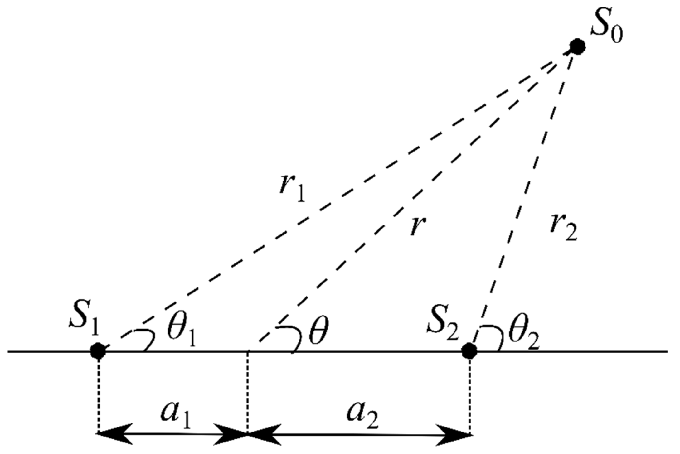
Figure 1. Geometrical sketch for the formulation of unsymmetrical doublet flow general equation.
Symmetry 14 00391 g001
Figure 2. Spatial stencils of finite differencing for Equations (16) and (17).
Symmetry 14 00391 g002
Figure 3. Algorithm for the semi-analytical method for unsymmetrical doublet flow.
Symmetry 14 00391 g003
Figure 4. Unsymmetrical doublet flow structure when the strength of sink is at (a) 3 m ^ , (b) 5 m ^ , and (c) 7 m ^ .
Symmetry 14 00391 g004aSymmetry 14 00391 g004b
Figure 5. Stagnation point and stagnation line profile for unsymmetrical doublet flow.
Symmetry 14 00391 g005
Figure 6. Unsymmetrical doublet flow structure when a2 = 0.5 while (a) a1 = 0.4 and (b) a1 = 0.2, with the strength of source and sink is 2 m ^ and 7 m ^ , respectively.
Symmetry 14 00391 g006
Figure 7. Altered Rankine oval flow structure when strength of source and sink is 2 m ^ and 5 m ^ , respectively, for (a) U = 5 m ^ , (b) U = 20 m ^ , (c) U = –5 m ^ , and (d) U = −20 m ^ .
Symmetry 14 00391 g007aSymmetry 14 00391 g007bSymmetry 14 00391 g007c
Figure 8. Secondary aerodynamic line for the sink-dominant superposed flow. The red circle represents the discontinued spots.
Symmetry 14 00391 g008
Figure 9. Altered Rankine oval flow structure when strength of source and sink is 5 m ^ and 2 m ^ , respectively, for (a) U = 5 m ^ , (b) U = 20 m ^ , (c) U = −5 m ^ , and (d) U = −20 m ^ .
Symmetry 14 00391 g009aSymmetry 14 00391 g009b
Figure 10. Streamline evolution due to increasing far-field velocity of (a) U = 2 m ^ and (b) U = 4 m ^ , and (c) U = 6 m ^ , when strength of source and sink is 5 m ^ and 2 m ^ , respectively.
Symmetry 14 00391 g010aSymmetry 14 00391 g010b
Figure 11. Aerodynamic line for the source-dominant superposed flow with: (a) ψ = 0.38 at U = 5 m ^ and (b) ψ = 14.8 at U = 20 m ^ .
Symmetry 14 00391 g011aSymmetry 14 00391 g011b
Figure 12. Breakdown of Rankine oval flow structure when strength of source and sink is 5 m ^ and 2 m ^ , respectively, for (a) U = 20 m ^ at θ = 45°, (b) U = 80 m ^ at θ = 45°, (c) U = 20 m ^ at θ = 90°, (d) U = 80 m ^ at θ = 90°, (e) U = 20 m ^   at θ = 135°, and (f) U = 80 m ^ at θ = 135° (yellow spots represent the stagnation point).
Symmetry 14 00391 g012aSymmetry 14 00391 g012bSymmetry 14 00391 g012c
Figure 13. Approximation of morphology of Carangiform swimmer using general doublet equation (modified from the work of Junqiang et al. [61]).
Symmetry 14 00391 g013
Table 1. Tangential function for tan (αgθg) at 2 ≤ αg ≤ 10.
αgtan (αgθg)
2 2 tan θ g 1 tan 2 θ g
3 3 tan θ g tan 3 θ g 1 3 tan 2 θ g
4 4 tan θ g 4 tan 3 θ g 1 6 tan 2 θ g + tan 4 θ g
5 5 tan θ g 10 tan 3 θ g + tan 5 θ g 1 10 tan 2 θ g + 5 tan 4 θ g
6 6 tan θ g 20 tan 3 θ g + 6 tan 5 θ g 1 15 tan 2 θ g + 15 tan 4 θ g tan 6 θ g
7 7 tan θ g 35 tan 3 θ g + 21 tan 5 θ g tan 7 θ g 1 21 tan 2 θ g + 35 tan 4 θ g 7 tan 6 θ g
8 8 tan θ g 56 tan 3 θ g + 56 tan 5 θ g 8 tan 7 θ g 1 28 tan 2 θ g + 70 tan 4 θ g 28 tan 6 θ g + tan 8 θ g
9 9 tan θ g 84 tan 3 θ g + 126 tan 5 θ g 36 tan 7 θ g + tan 9 θ g 1 36 tan 2 θ g + 126 tan 4 θ g 84 tan 6 θ g + 9 tan 8 θ g
10 10 tan θ g 120 tan 3 θ g + 252 tan 5 θ g 120 tan 7 θ g + 10 tan 9 θ g 1 45 tan 2 θ g + 210 tan 4 θ g 210 tan 6 θ g + 45 tan 8 θ g tan 10 θ g
Publisher’s Note: MDPI stays neutral with regard to jurisdictional claims in published maps and institutional affiliations.