Article

A Symmetric Novel 8T3R Non-Volatile SRAM Cell for Embedded Applications

by
Uma Maheshwar Janniekode
1,
Rajendra Prasad Somineni
1,
Osamah Ibrahim Khalaf
2,
Malakeh Muhyiddeen Itani
3,
J. Chinna Babu
4,* and
Ghaida Muttashar Abdulsahib
5
1
VNR Vignana Jyothi Institute of Engineering and Technology, JNTUH University, Hyderabad 500085, India
2
Al-Nahrain Nanorenewable Energy Research Center, Al-Nahrain University, Baghdad 64074, Iraq
3
General Education Program, Dar Al-Hekma University, Jeddah 22246, Saudi Arabia
4
Department of ECE, Annamacharya Institute of Technology and Sciences, Rajampet 516126, India
5
Department of Computer Engineering, University of Technology, Baghdad 19006, Iraq
*
Author to whom correspondence should be addressed.
Symmetry 2022, 14(4), 768; https://doi.org/10.3390/sym14040768
Submission received: 11 February 2022 / Revised: 21 March 2022 / Accepted: 1 April 2022 / Published: 7 April 2022

Abstract

:
This paper proposes a symmetric eight transistor-three-memristor (8T3R) non-volatile static random-access memory (NVSRAM) cell. Non-volatile operation is achieved through the use of a memristor element, which stores data in the form of its resistive state and is referred to as RRAM. This cell is able to store the information after power-off mode and provides fast power-on/power-off speeds. The proposed symmetric 8T3R NVSRAM cell performs better instant-on operation compared to existing NVSRAMs at different technology nodes. The simulation results show that resistance of RAM-based 8T3R SRAM cell consumes less power in standby mode and has excellent switching performance during power on/off speed. It also has better read and write stability and significantly improves noise tolerance than the conventional asymmetrical 6T SRAM and other NVSRAM cells. The power dissipation is evaluated at different technology nodes. Hence, our proposed symmetric 8T3R NVSRAM cell is suitable to use at low power and embedded applications.

1. Introduction

Over the past decades, metal oxide-based memories such as SRAM, DRAM, and flash memory have been generally used to meet the capacity prerequisites of any data handling unit [1]. The expanse of mobile devices has prompted the need to plan storage devices with fast switching characteristics longer and battery life [2]. Despite the fact that it is fast, the volatile nature of SRAM can cause stored data to be lost when the power supply is removed [3]. Moreover, under the deep submicron range, SRAM cells encounter high leakage power consumption [4]. The CMOS technology is also moving toward the fundamental limit of size scaling [5] because of the expanded short-channel effect, seriously weakening device performance [6]. Therefore, to address the issues of normally-off applications, non-volatile memory (NVM) is generally used to back up the information in the SRAM when the power is off [7]. It is recommended that non-volatile memory (NVM) devices can further suppress standby power consumption by turning off the power of infrequently used SRAMs without loss of information. Before turning off the power of the SRAM cell, first store the SRAM data in the NVM device. After power-up, the data are restored again. Hence, Such SRAM cells can be called non-volatile SRAM (NVSRAM). Compared with the use of high threshold voltage (High Vth) to maintain the latch, this design dissipates much less leakage power to hold the data of the SRAM cell [8]. Among the different types of NVM devices, memristors (also called resistive random-access memory, RRAM) based devices have certain benefits, including a small size (with dimensions 10 nm× 10 nm as described in [9]); high-speed operation, approximately 10 ns [10,11]; low programming voltage, approximately 1 V programming voltage as described in [12]; and compatible with CMOS manufacturing process.
Memristor was discovered by Leon Chua in the early 1970s, which established the relation between flux (Φm) and charge (q) and was able to maintain its resistive state even after removing the power supply [2]. The internal state variable (xm) performs the role of the memristance (M) of the memristors, i.e., xm ≡ M [13]. The state of the memristor is defined by the following equation
i(t) = xm − (v(t))
The memristor is a two-terminal device, originally considered to be the fourth passive element after the capacitor (C), inductor (L), and resistor (R) [14]. It is a non-linear switching mechanism of memristor that involves the operation of forming conductive filaments with oxide layers between the metal terminals to achieve a low-resistance state and high-resistance state of the device [15]. The magnitudes of these resistance states can have a different values. The external voltage applied determines the resistances states of the device. In addition, the use of memristors was proven to consume less power and high packaging density. Memristors can be used in many fields, such as the design of chaotic circuits [15,16,17], analog circuits [18], neural networks [19,20,21], logic arrays [22,23], and flip-flop [24]. In this article, a novel 8T3R NVSRAM is proposed that has dominance energy, noise immunity, and delay in terms of read and write operations than the traditional 6T SRAM cell design. The main features of this work are:
  • Symmetric NVSRAM has shown improvements in standby power consumption and static noise margin when compared with standard 6T SRAM (S6T) cell;
  • Using a memristor ensures that the circuit is inherently non-volatile.
The other sections of this paper discuss the following: In Section 2, a brief overview of NVM structure and operation flow is provided. Section 3 discusses the operation of the proposed symmetric 8T3R NVSRAM cell design at different operating modes, such as the store, power down, and restore operations, which are explained. The simulation results obtained were discussed in Section 4 and compared with other conventional CMOS 6T SRAM cells and NVSRAM cells. Finally, Section 5 concludes the paper.

2. NVSRAM Cell Design

The NVM with SRAM makes symmetric NVSRAM. The performance factors used for the NVM and SRAM are symmetrical in nature. Figure 1a shows the structure of symmetric NVSRAM with a combination of a single symmetric SRAM cell and NVM device. The NVM device is connected to data nodes Q and QBAR, which access the information from it and stores it for future purpose. Figure 1b shows the operational flow of the symmetric NVSRAM. In normal mode, the NVSRAM cell acts as an SRAM and performs functions similar to the SRAM cell and performs read/write operations [25]. In standby mode, symmetric NVSRAM enters the storage operation by pushing the SRAM cell data into the memristor devices with raise of control voltages [26]. The memristor is set to High-Resistance State (HRS)/Low-Resistance State (LRS) depending on the data present at nodes. The LRS represents the SET state, and HRS represents the RESET state [27,28]. After successfully backing up the data, the standby leakage power is reduced by shutting into power-down mode [29,30]. The previous data from the memristor to the data nodes are restored again whenever the NVSRAM cell is powered up [31,32,33,34]. After RESTORE operation, symmetric NVSRAM can be used as normal SRAM for read/write operations [34,35,36,37].

2.1. Existing NVSRAM Cells

The existing structures of non-volatile SRAM cells are depicted in Figure 2.

2.1.1. 8T2R

The 8T2R based NVSRAM is shown in Figure 2a. RRAMs can be accessed by passing a CTRL1 signal to two transistors, M7 and M8, which are used to perform SET and RESET, respectively. Assuming that the SET signal is received, CTRL1 is set to high, while CTRL2 is grounded, and, depending on the data stored in the NVSRAM cell, either R1 or R2 is set to LRS (low-level read-write). During the RESET process, CTRL2 is set to VDD, and either R1 or R2 is set to HRS, depending on the data stored in the NVSRAM cell. The current drive capability of the F-MOSFET is improved for the NVSRAM application, but the mode of operation dissipates more power in write and power-down mode.

2.1.2. 7T1R

Figure 2b shows the structure of the 7T1R NVSRAM cell [32]. The cell consists of seven Transistors and one RRAM comprised of 6TSRAM cells and 1T1R. The STORE operation is controlled by control transistor M7, which is connected between the RRAM device and memory node Q, which stores the logic states “0” and “1”. The RRAM device’s LRS and HRS are determined by the data stored at nodes Q and QBAR. Because there is only one RRAM device, the FORMING state is performed using BL at the start of the storing operation.
During the power-down stage, all voltage sources are switched off. During the RESTORE procedure, the current from CTRL2 passes through the RRAM device depending on the resistive state. When the RRAM is in LRS, for example, Q stays at “1”, and Qb is discharged through M2. When CTRL1 and WL are set to high during READ, the amount of current flow is determined by the potential difference between the top and bottom electrodes of the RRAM device. Node Q is linked to BL to check the status of the memory cell. This design shows a significant reduction in energy for its operations required for “Instant-on” operation and is capable of storing and operating under multiple sets of configuration data for FPGA operation. However, a low restore yield degraded with stability margins tried to enhance the stability of the cell, but they used an additional source switch transistor that acquires extra area and increases the threshold value of voltage transfer characteristics (VTCs), which introduces a delay in the circuit.

2.1.3. 7T2R

The structure of 7T2R [31] is shown in Figure 2c, with RRAMs R1 and R2. R1 is connected to M7, and R2 is connected to common sources of M3 and M4. STORE/RESTORE actions are controlled by the M5 transistor. It should be noted that the FORMING procedure for R1 is carried out by a single BL. RRAM resistance varies from LRS to HRS or HRS to LRS during STORE, depending on the Q and Qb node voltages, as long as the CTRL1 signal is set high. WL and CTRL1 are set high during the read operation. The WRITE “0” and “1” commands are programmed into Nodes Q. BL is high to SET R1 during the STORE operation and low to RESET. If the RRAM device is in LRS mode, Node Q retains “1” during RESTORE and “0” if it is in HRS mode. Stability was improved, but with this model, the power dissipation rises ten times for the increase of every 100 K temperature.
One key challenge to RRAM cells is the write endurance. Endurance is usually defined as the number of set-reset operations (i.e., endurance cycles) after which the cell experiences a permanent-write failure. Several papers [38,39] demonstrated up to 106 endurance cycles at the array level.

3. Proposed Symmetric 8T3R NVSRAM Cell

This section may be divided into subheadings. It should provide a concise and precise description of the experimental results, their interpretation, as well as the experimental conclusions that can be drawn.

3.1. Structure

The proposed structure of the symmetric 8T3RNVSRAM cell is shown in Figure 3. The cell is comprised of a core 6T-SRAM cell (M1–M6), NMOS control transistors (M7, M8) and memristors R1, R2 (connected to data nodes through control transistors), and memristor R3 is connected to the common sources of pull-down transistors M3 and M4 with control signal CTRL3. This memristor R3 avoids direct connection between SRAM cell core and ground Vss. The CTRL3 makes the cell in a stable state by providing low voltage in the read mode. The data are stored in R1 and R2 by enabling the M7 and M8 with control signals CTRL1 and CTRL2. The logic state of memristor “1” represents STORE, and logic “0” represents the RESET state. The operation of the 8T3R NVSRAM cell follows the following sequence: normal SRAM operation (READ/WRITE), RESET, STORE, POWER-DOWN, and POWER-UP/RESTORE.
The following subsections illustrate the complete sequence of NVSRAM operation-the bias conditions for the different operating modes of the RESTORE cycle. The bias conditions used for the memristor device with the control signals are summarized in Table 1.
The text continues here (Figure 2 and Table 2).

3.2. Normal SRAM Operation

During normal SRAM operation, read/write operations are not affected by the presence of memristors R1 and R2 as they are separated from the core SRAM cell by M7 and M8, which are turned OFF with CTRL1 = CTRL2 = 0 V, and memristor R3 is also used to stabilize the read and write operations with CTRL3 = 0 V in write mode and −1 V in the read mode.

3.3. RESET Operation

A RESET operation is performed before storing the data into the memristors in order to ensure no logic state has been set in the memristors previously. R1/R2 can be made to RESET by closing the control transistors M7 and M8 with CTRL1 and enabling CTRL2 to 1 V.

3.4. STORE Operation

After the RESET operation, the STORE operation is performed by enabling the control transistors M7 and M8 through CTRL1. The memristors R1 and R2 store the values of data nodes Q and QBAR. The logic is stored in R1, and R2 is in the form resistance state. For instance, if Q = 1, a positive potential difference is generated at the top and bottom electrodes and sets the memristor in LRS; when Q = 0, it creates a negative potential difference that sets it in HRS. The LRS state represents the logic “1”, and HRS represents logic “0”.

3.5. POWER DOWN Operation

The condition for POWER-DOWN operation is obtained by making all the control signals and supply to the ground.

3.6. RESTORE Operation

The RESTORE operation is performed by enabling the controls signals at NMOS transistors. The nodes Q and QBAR retrieve the data by accessing the potential voltage drop created at memristors. If Q stored logic “0”, then it is set in the LRS state; this makes the node voltage Q to HIGH, which is enough to turn ON pull-down transistor M4. Thus, the node QBAR is pulled down to logic “0”, which in turn makes the Q to logic “1”. In this way, the data are restored in the SRAM core cell, which constitutes an NVSRAM cell.

3.7. Evaluation of Non-Volatility

The conventional symmetry-based SRAM cell (Figure 1) is inherently volatile because it cannot store information when the supply is removed, so 8T2R NVSRAM [30] was introduced to store the data node information in RRAM and restores it again when the supply is turned ON. Even though this cell is non-volatile but it has less stability. Hence, the proposed design symmetric 8T3R NVSRAM cell overcomes stability issues as well as non-volatile properties. This RRAM-based NVSRAM acquires the properties of non-volatile and is able to store the information contained in the core SRAM cell when the power is OFF with the aid of control transistors and retains the data back whenever the supply is ON.
In order to assess SRAM as symmetric NVSRAM, the following four basic working operation principles of R1, R2, and R3 are explained: (i) initial state or the normal state of SRAM, (ii) store state (NVM state), (iii) power down (VDD = 0 V), and (iv) restore state (VDD = HIGH) with the control signals (CTRL). CTRL1 = 0, CTRL2 = 0 shows that there is no connection between the RRAM’s R1, R2, and the output nodes of the back-to-back inverters of the core 6T SRAM cell. Therefore, making control signals to shut down normal SRAM operation is achieved. In order to store the information or to make SRAM as NVSRAM, the control signals CTRL1 and CTRL2 are enabled high. The data are stored in a memristor or RRAM in the form of resistance states. For instance, if node Q stores the logic “0”, then R1 is in HRS and R2 is in LRS (QBAR = 1), and vice versa.
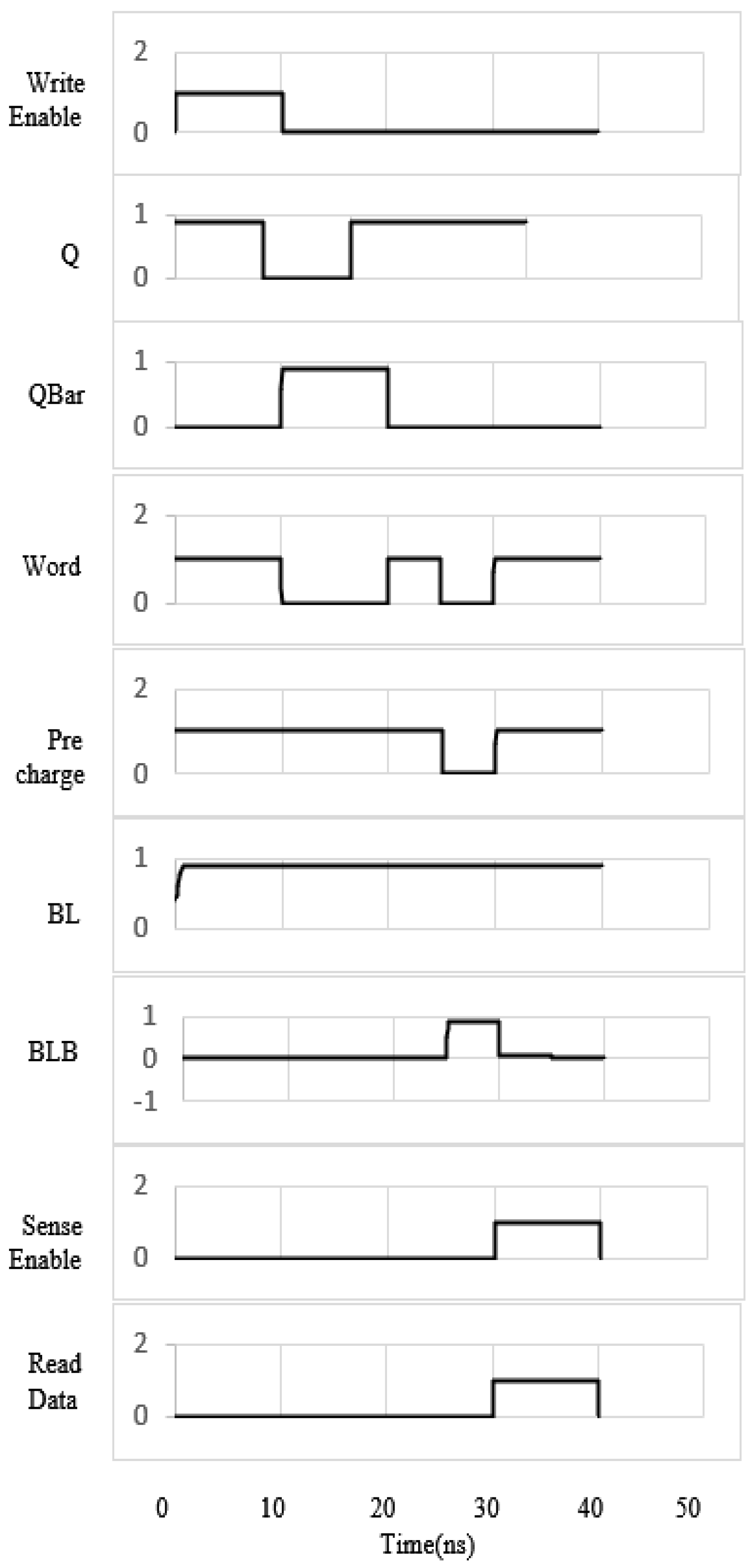
The advantage of Q = 0 is that in both operations, such as store and restore, there is no need to change the state of the memristor, which already stays in HRS. If the power and all the control signals are shut down, the information is stored in the memristor with its HRS and LRS states. The original data are restored by enabling the CTRL1, CTRL2, and VDD. After all operations such as store, power down, and restore, the memristor at the data node storing logic “0” comes into HRS. Therefore, it does not require additional reset after successful restore, 0, which was required for 8T2R [30] and 7T1R [32]. The non-volatility operation of 8T3R NVSRAM was studied by using HSPICE simulation. The timing diagram (Figure 4) explains the steps involved in the store and restore operations. After successfully writing data into the nodes Q and QBAR, the data are stored from Q into R1 and QBAR into R2. From the timing diagram, the first cycle shows the write enable signal given to write circuitry.
In writing “Q = 1,” VDD, WL, and BL are enabled high, while BLB, CTRL1, CTRL2, and CTRL3 are maintained low. The seventh and eighth cycles show the data written into the cell for the first 10 ns with Q at logic HIGH and QBAR at logic LOW. After 10 ns, the power supply is removed, and all the control signals WL, CTRL1, and CTRL2 are changed to LOW, shown in the third, fourth and fifth cycles. After power down, the memristor R1 is SET to LRS, and R2 is RESET to HRS. During a restore operation, VDD, CTRL1, and CTRL2 are enabled after 20 ns. CTRL1 and CTRL2 again setups a connection between the R1–R2 and the cell nodes, which forces R1, R2 to retrieve the lost data into nodes Q and QBAR. This can be observed in the last cycles after 20 ns. After all cycles of operation, the 8T3R NVSRAM cell comes to its initial mode or its normal mode. Therefore, the SRAM cell becomes NVSRAM by storing the lost data. The read operation of restored data NVSRAM cell is similar to normal SRAM cell operation. After restoring the data to the nodes, the cell data value is called through pre charge and sense amplifier circuits, which show the timing, as demonstrated in the diagram (Figure 5).

4. Simulation Results and Discussion

Performance Parameters of Proposed Symmetric 8T3R NVSRAM

This paper proposed a novel 8T3R NVSRAM cell, which is designed and simulated by using the SYNOPSYS HSPICE tool, and evaluated various cell parameters, such as read delay, write delay, read SNM (RSNM) and write SNM (WSNM), static and dynamic power dissipation at different technology nodes of [19], and the spice memristor model [3]. The formation of a conductive oxygen layer between two terminals determines the HRS and LRS of the memristor [26]. The condition parameters of memristor HRS (ROFF), LRS (RON), and mobility µv are chosen as 16 KΩ, 100 Ω, and 10−14 m2 v−1 S−1, respectively. The length “D” of the semiconductor film is taken as 10 nm. The linear charge control memristor can be modeled as two resistors in series according to the following formula:
R ( w ) = R ON × w D + R OFF ( 1 w D )
M ( q ) = R OFF ( 1 μ V R ON q ( t ) D 2 )
where M(q) is the overall memristance of the memristor, RON and ROFF are the ON state and OFF state resistances, D is the device length, and µv is the mobility of oxygen ions. The static noise margin (SNM) is calculated from butterfly curves by plotting Q and QB VTC characteristics under DC conditions. For proper comparison, the technology is scaled up to 16 nm Predictive Technology Model. The condition parameters for symmetric NVSRAM simulation at different technology nodes are tabulated in Table 2.
The simulation results of power dissipation in terms of static and dynamic and delays in terms of read and write are summarized in Table 3. It can be seen that compared with the traditional 6TSRAM, the read and write SNM of the proposed 8T3R NVSRAM structure has been improved by 10% and 20%, respectively. It is found that the total power dissipation of 8T3R is 22.65% less than 6T SRAM cells.
Table 4 shows the performance parameters comparison results of 6T, 7T1R [32], 7T2R [23], 8T2R [30], and proposed 8T3R at 16 nm. The SNM graphs are in terms of hold, read, and write (Figure 6). The comparison graphs for 6T SRAM, NVSRAMs, and proposed 8T3R NVSRAM are compared at technology nodes 32 nm, 22 nm, 20 nm, and 16 nm, as shown in Figure 7, Figure 8, Figure 9, Figure 10, Figure 11 and Figure 12.
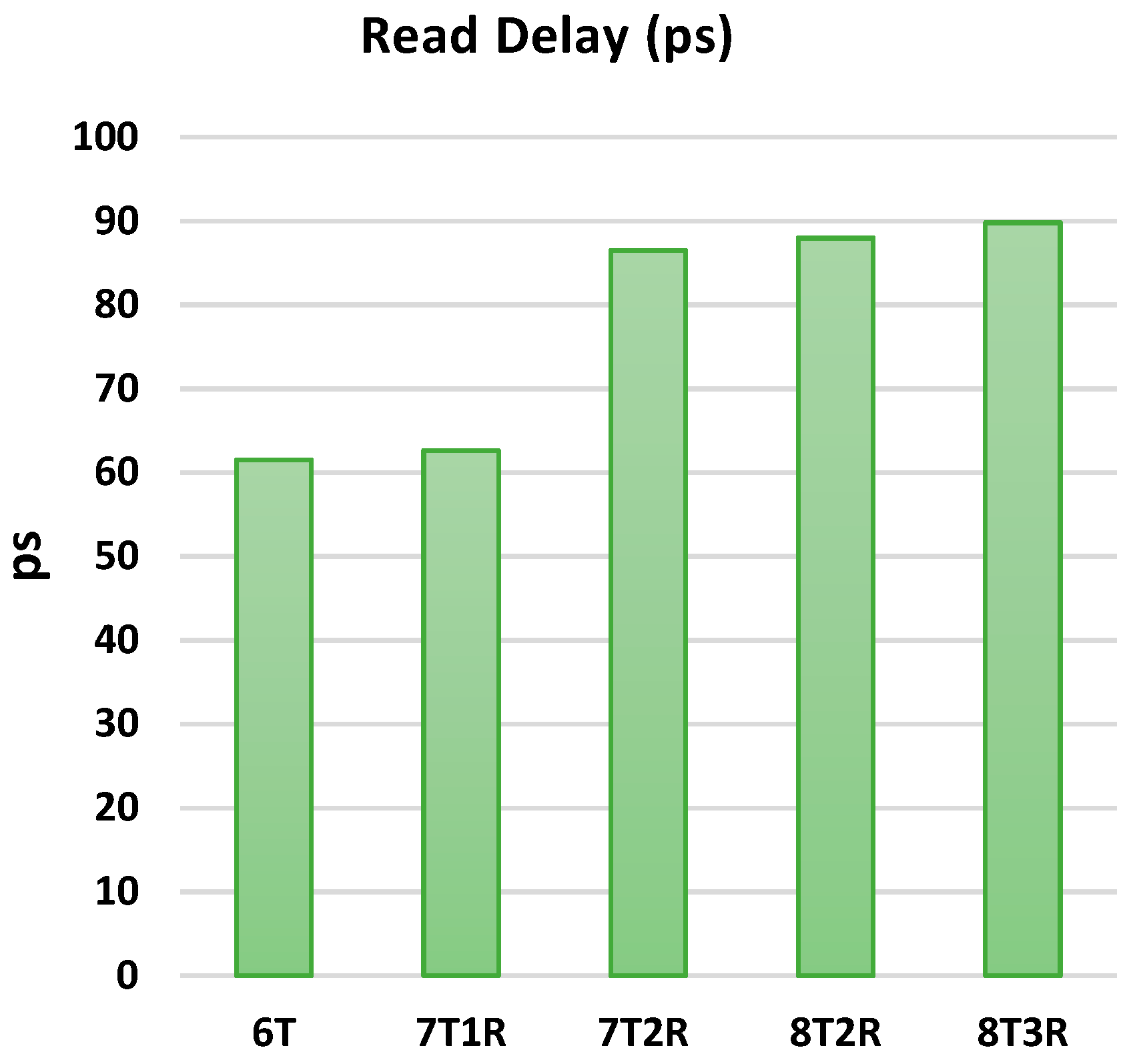
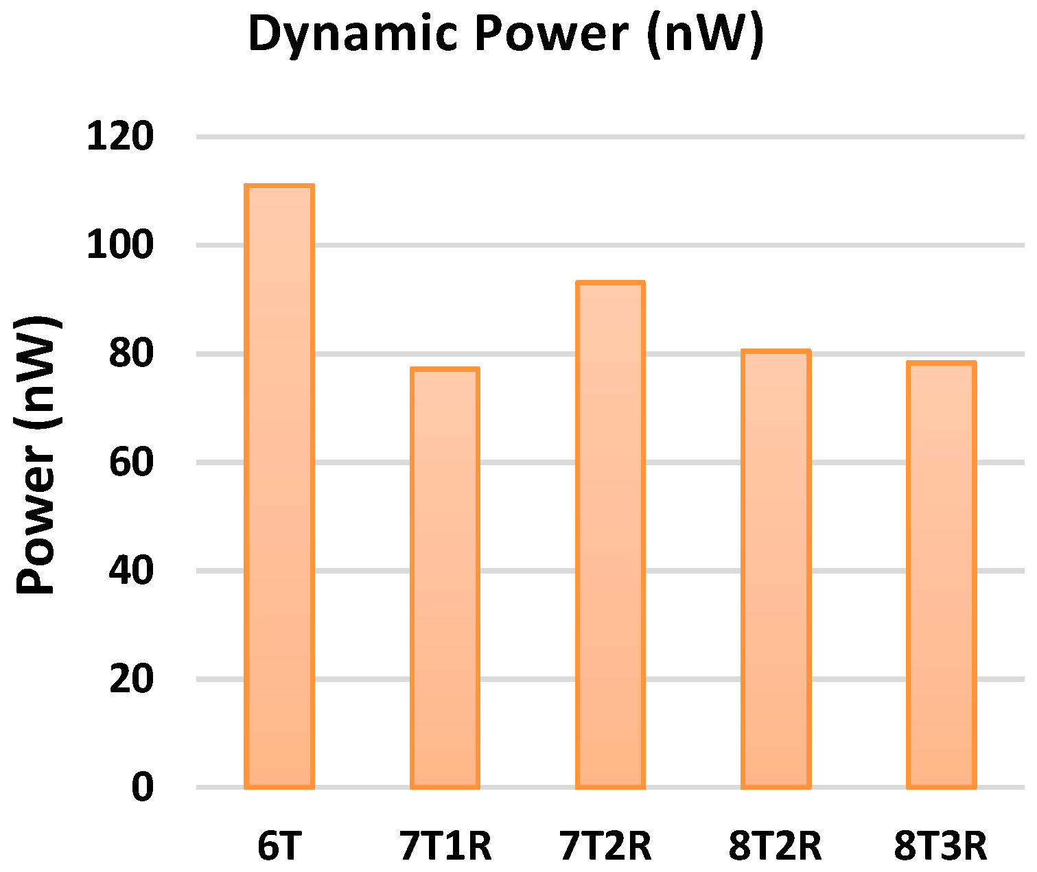
The clear observation is made by plotting the graphs of parameters such as delays, static and dynamic powers, read and write stability margins of NVSRAMs, and proposed 8T3R NVSRAM cells at 16 nm node. Even though the proposed cell takes compatible delays shown in Figure 13 and Figure 14, the static or standby power dissipation of the proposed 8T3R NVSRAM is significantly reduced with respect to 6T SRAM. The other parameter, such as dynamic power, is greatly reduced. The proposed cell consumes less power than all other NVSRAMs and as well as conventional 6T SRAM cell (Figure 11 and Figure 12). It is decreased by an average of 28%. The static and dynamic power at 16 nm technology is represented in Figure 15 and Figure 16. This design improved both the stability margins, read and write (Figure 9 and Figure 10). The additional memristor used at NMOS transistors M3 and M4 improved read stability (Figure 17), with respect to 6T, 7T1R [32], 7T2R [23], and 8T2R [30], by 21%, 42%, 5%, 15%, respectively. From Figure 18, the WSNM over 6T, 7T1R [32], and 8T2R [30] is improved by 16%, 10%, and 7%, respectively.
In summary, the proposed 8T3R design shows better performance than the 6T SRAM cell in terms of stability and power consumption and achieves non-volatile properties by using memristors. It also marks superior among the other NVSRAMs in terms of stability and power consumption.

5. Conclusions

In this paper, a memristor-based symmetric 8T3R NVSRAM cell is designed and analyzed its performance at different technology nodes and compared with conventional 6T SRAM cells and other existing NVSRAM cells. The memristor R3 is connected at the source terminals of the NMOS transistors M3 and M4 and is used to stabilize read/write SNM, and the other two are connected at the data node of the core SRAM cell, which assesses SRAM as NVSRAM. The symmetric 8T3R NVSRAM cell successfully performed “normal SRAM, RESET, STORE, POWER DOWN, and RESTORE” operations. The read and write stability are improved by 10% and 20%, respectively; the static and dynamic power are also reduced by 15% and 28%, respectively, to conventional 6T SRAM cells. Compared with other NVSRAMs, this proposed cell consumes less dynamic power since no additional RESET operation is required. This design has lower power dissipation because leakage power is reduced by using the NMOS M3 and M4 source memristor. Moreover, it has greater read and write stability than all other NVSRAMs discussed above. Due to higher stability and less power consumption, and leakage power, this work may provide a design and optimization method for non-volatile SRAM with RRAM devices. The designed symmetric 8T3R NVSRAM is feasible to assist normally off-computing applications. Hence, the memristor-based 8T3RNVSRAM cell constitutes a better non-volatile memory cell.

Author Contributions

Conceptualization, U.M.J.; methodology, U.M.J.; software, U.M.J.; validation, J.C.B.; formal analysis, U.M.J., O.I.K. and M.M.I.; data curation, R.P.S. and J.C.B.; Writing-original draft, R.P.S.; writing-review and editing, J.C.B.; supervision, G.M.A.; project administration, O.I.K.; funding acquisition, M.M.I. All authors have read and agreed to the published version of the manuscript.

Funding

This research received no external funding.

Institutional Review Board Statement

Not applicable.

Informed Consent Statement

Not applicable.

Data Availability Statement

Not applicable.

Conflicts of Interest

The authors declare no conflict of interest.

References

  1. Meena, J.S.; Sze, S.M.; Chand, U.; Tseng, T.Y. Overview of emerging nonvolatile memory technologies. Nanoscale Res. Lett. 2014, 9, 526. [Google Scholar] [CrossRef] [PubMed] [Green Version]
  2. Zidan, M.A.; Fahmy, H.A.H.; Hussain, M.M.; Salama, K.N. Memristor-based memory: The sneak paths problem and solutions. Microelectron. J. 2013, 44, 176–183. [Google Scholar] [CrossRef] [Green Version]
  3. Biolek, D.; Ventra, M.D.I.; Pershin, Y.V. Reliable SPICE Simulations of Memristors, Memcapacitors and Meminductors Reliable Modeling of Memelements with SPICE. Radioengineering 2013, 22, 945. [Google Scholar]
  4. Buscarino, A.; Fortuna, L.; Frasca, M.; Gambuzza, V.L. A chaotic circuit based on Hewlett-Packard memristor A chaotic circuit based on Hewlett-Packard memristor. Chaos 2012, 22, 023136. [Google Scholar] [CrossRef] [PubMed]
  5. Cai, H.; Wang, Y.; Naviner, L.A.D.B.; Zhao, W. Robust Ultra-Low Power Non-Volatile Logic-in-Memory Circuits in FD-SOI Technology. IEEE Trans. Circuits Syst. I Regul. Pap. 2017, 64, 847–857. [Google Scholar] [CrossRef]
  6. Chen, P.; Member, S.; Yu, S. Compact Modeling of RRAM Devices and Its Applications in 1T1R and 1S1R Array Design. IEEE Trans. Electron Devices 2015, 62, 4022–4028. [Google Scholar] [CrossRef]
  7. Chiu, P.-F.; Chang, M.-F.; Wu, C.-W.; Chuang, C.-H.; Sheu, S.-S.; Chen, Y.-S.; Tsai, M.-J. Low store energy, low VDD min, 8T2R nonvolatile latch and SRAM with vertical-stacked resistive memory (memristor) devices for low power mobile applications. IEEE J. Solid-State Circuits 2012, 47, 1483–1496. [Google Scholar] [CrossRef]
  8. Chua, L.O. Memristor—The missing circuit element. EEE Trans. Circuit Theory 1971, 18, 507–519. [Google Scholar] [CrossRef]
  9. Garc, F.; Member, S.; Marisa, L. On the Design and Analysis of Reliable RRAM-CMOS Hybrid Circuits. IEEE Trans. Nanotechnol. 2017, 16, 514–522. [Google Scholar]
  10. Halawani, Y.; Mohammad, B.; Homouz, D.; Al-Qutayri, M.; Saleh, H. Modeling and Optimization of Memristor and STT-RAM-Based Memory for Low-Power Applications. IEEE Trans. Very Large Scale Integr. Syst. 2016, 24, 1003–1014. [Google Scholar] [CrossRef]
  11. Hu, J.; Stecklein, G.; Anugrah, Y.; Crowell, P.A.; Koester, S.J. Using Programmable Graphene Channels as Weights in Spin-Diffusive Neuromorphic Computing. IEEE J. Explor. Solid-State Comput. Devices Circuits 2018, 9231, 26–34. [Google Scholar] [CrossRef]
  12. Jiang, Z.; Yu, S.; Wu, Y.; Engel, J.H.; Guan, X.; Wong, H.-S.P. Verilog-A Compact Model for Oxide-based Resistive Random Access Memory (RRAM). In Proceedings of the 2014 International Conference on Simulation of Semiconductor Processes and Devices (SISPAD), Yokohama, Japan, 9–11 September 2014; pp. 41–44. [Google Scholar]
  13. Pal, S.; Bose, S.; Islam, A. Design of memristor based low power and highly reliable ReRAM cell. Microsyst. Technol. 2019. [Google Scholar] [CrossRef]
  14. Lehtonen, E.; Poikonen, J.H.; Laiho, M. Applications and limitations of memristive implication logic. In Proceedings of the 2012 IEEE International Symposium on Circuits and Systems (ISCAS), Seoul, Korea, 20–23 May 2012. [Google Scholar]
  15. Lu, W.; Lieber, C.M. Nanoelectronics from the bottom up. Nat. Mater. 2007, 6, 841–850. [Google Scholar] [CrossRef] [PubMed]
  16. Mountain, D.J.; Member, S.; Mclean, M.M. Memristor Crossbar Tiles in a Flexible, General Purpose Neural Processor. IEEE J. Emerg. Sel. Top. Circuits Syst. 2017, 8, 137–145. [Google Scholar] [CrossRef]
  17. Ni, L.; Liu, Z.; Yu, H.A.O.; Joshi, R.V. An Energy-Efficient Digital ReRAM-Crossbar-Based CNN with Bitwise Parallelism. IEEE J. Explor. Solid-State Comput. Devices Circuits 2017, 3, 37–46. [Google Scholar] [CrossRef]
  18. Pal, S.; Gupta, V.; Islam, A. Variation resilient low-power memristor-based synchronous flip-flops: Design and analysis. Microsyst. Technol. 2021, 27, 525–538. [Google Scholar] [CrossRef]
  19. Predictive Technology Model (PTM). 2012. Available online: https://ptm.asu.edu/ (accessed on 10 August 2019).
  20. Prasad, S.R.; Madhavi, B.K.; Kishore, K.L. Data-Retention Sleep Transistor CNTFET SRAM Cell Design at 32 nm Technology for Low-Leakage. In Proceedings of the 2nd International Conference on Advances in Information Technology and Mobile Communication—AIM 2012, Bangalore, India, 27–28 April 2012; pp. 362–368. [Google Scholar]
  21. Sakib, M.N.; Hassan, R.; Biswas, S.N.; Das, S.R. Memristor-Based High-Speed Memory Cell with Stable Successive Read Operation. IEEE Trans. Comput. Des. Integr. Circuits Syst. 2018, 37, 1037–1049. [Google Scholar] [CrossRef]
  22. Shin, S.; Kim, K.; Member, A.; Kang, S.-M. Memristor Applications for Programmable Analog ICs. IEEE Trans. Comput.-Aided Des. Integr. Circuits Syst. 2011, 10, 266–274. [Google Scholar]
  23. Singh, J.; Raj, B. Design and Investigation of 7T2M-NVSRAM With Enhanced Stability and Temperature Impact on Store/Restore Energy. IEEE Trans. Very Large Scale Integr. Syst. 2009, 27, 1322–1328. [Google Scholar] [CrossRef]
  24. Kanno, Y.; Mizuno, H.; Yasu, Y.; Hirose, K.; Shimazaki, Y.; Hoshi, T.; Miyairi, Y.; Ishii, T.; Yamada, T.; Irita, T.; et al. Hierarchical Power Distribution with Power Tree in Dozens of Power Domains for 90-nm Low-Power. IEEE J. Solid-State Circuits 2007, 42, 74–83. [Google Scholar] [CrossRef]
  25. Strachan, J.P.; Torrezan, A.C.; Miao, F.; Pickett, M.D.; Yang, J.J.; Yi, W.; Medeiros-Ribeiro, G.; Williams, S. State Dynamics and Modeling of Tantalum Oxide Memristors. IEEE Trans. Electron Devices 2013, 60, 2194–2202. [Google Scholar] [CrossRef]
  26. Strukov, D.B.; Snider, G.S.; Stewart, D.R.; Williams, R.S. The missing memristor found. Nature 2008, 453, 80–84. [Google Scholar] [CrossRef] [PubMed]
  27. Sun, J.; Shen, Y.; Yin, Q.; Xu, C. Compound synchronization of four memristor chaotic oscillator systems and secure communication Compound synchronization of four memristor chaotic oscillator systems and secure communication. Chaos Interdiscip. J. Nonlinear Sci. 2013, 23, 013140. [Google Scholar] [CrossRef] [PubMed]
  28. Swami, S.; Mohanram, K. Reliable Nonvolatile Memories: Techniques and Measures. IEEE Des. Test 2017, 34, 31–41. [Google Scholar] [CrossRef]
  29. Janniekode, U.M.; Somineni, R.P.; Naidu, C.D. Design and Performance Analysis of 6T SRAM Cell in Different Technologies and Nodes. Int. J. Perform. Eng. 2021, 17, 167–177. [Google Scholar]
  30. Yamamoto, S.; Shuto, Y.; Sugahara, S. Nonvolatile SRAM (NV-SRAM) using functional MOSFET merged with resistive switching devices. In Proceedings of the 2009IEEE Custom Integrated Circuits Conference, San Jose, CA, USA, 13–16 September 2009; pp. 531–534. [Google Scholar]
  31. Yang, J.J.; Strukov, D.B.; Stewart, D.R. Memristive devices for computing. Nat. Nanotechnol. 2013, 8, 13–24. [Google Scholar] [CrossRef] [PubMed]
  32. Wei, W.; Namba, K.; Han, J.; Lombardi, F. Design of a Nonvolatile 7T1R SRAM Cell for Instant-on Operation. IEEE Trans. Nanotechnol. 2014, 13, 905–916. [Google Scholar] [CrossRef]
  33. Palanisamy, S.; Thangaraju, B.; Khalaf, O.I.; Alotaibi, Y.; Alghamdi, S. Design and Synthesis of Multi-Mode Bandpass Filter for Wireless Applications. Electronics 2021, 10, 2853. [Google Scholar] [CrossRef]
  34. Rout, R.; Parida, P.; Alotaibi, Y.; Alghamdi, S.; Khalaf, O.I. Skin Lesion Extraction Using Multiscale Morphological Local Variance Reconstruction Based Watershed Transform and Fast Fuzzy C-Means Clustering. Symmetry 2021, 13, 2085. [Google Scholar] [CrossRef]
  35. García, N.O.; Velásquez, M.F.D.; Romero, C.A.T.; Monedero, J.H.O.; Khalaf, O.I. Remote Academic Platforms in Times of a Pandemic. Int. J. Emerg. Technol. Learn. 2021, 16, 121–131. [Google Scholar] [CrossRef]
  36. Khalaf, O.I.; Romero, C.A.T.; Pazhani, A.A.J.; Vinuja, G. VLSI Implementation of a High-Performance Nonlinear Image Scaling Algorithm. J. Healthc. Eng. 2021, 2021, 6297856. [Google Scholar] [CrossRef] [PubMed]
  37. Khalaf, O.I.; Abdulsahib, G.M. An Improved Efficient Bandwidth Allocation using TCP Connection for Switched Network. J. Appl. Sci. Eng. 2021, 24, 735–741. [Google Scholar] [CrossRef]
  38. Chen, Y.Y.; Govoreanu, B.; Goux, L.; Degraeve, R.; Fantini, A.; Kar, G.S.; Wouters, D.J.; Groeseneken, G.; Kittl, J.; Jurczak, M.; et al. Balancing SET/RESET Pulse for Endurance in 1T1R Bipolar RRAM. IEEE Trans. Electron Devices 2012, 59, 3243. [Google Scholar] [CrossRef]
  39. Grossi, A.; Vianello, E.; Sabry, M.M.; Barlas, M.; Grenouillet, L.; Coignus, J.; Beigne, E.; Wu, T.; Le, B.Q.; Wootters, M.K.; et al. Resistive RAM endurance: Array-level correction techniques targeting deep learning applications. IEEE Trans. Electron Devices 2019, 66, 1281–1288. [Google Scholar] [CrossRef]
Figure 1. (a) Structure for NVM with 6T SRAM cell as core. (b) Flow chart for operational flow of NVSRAM cell.
Symmetry 14 00768 g001
Figure 2. (a) Existing 7T1R NVSRAM 2. (b) Existing 7T2R NVSRAM 2. (c) Existing 8T2R NVSRAM.
Symmetry 14 00768 g002
Figure 3. Symmetric 8T3R NVSRAM Cell.
Symmetry 14 00768 g003
Figure 4. Non-volatile timing waveform of proposed 8T3R NVSRAM cell.
Symmetry 14 00768 g004
Figure 5. Read operation timing waveforms of proposed 8T3R NVSRAM.
Symmetry 14 00768 g005
Figure 6. SNM curves of hold, read, and write of proposed symmetric NVSRAM cell.
Symmetry 14 00768 g006
Figure 7. Write delay of different NVSRAMS and proposed NVSRAM cells.
Symmetry 14 00768 g007
Figure 8. Read delay of different NVSRAMS and proposed NVSRAM cells.
Symmetry 14 00768 g008
Figure 9. Read SNM of different NVSRAMS and proposed NVSRAM cells.
Symmetry 14 00768 g009
Figure 10. Write SNM of different NVSRAMS and proposed NVSRAM cells.
Symmetry 14 00768 g010
Figure 11. Static power dissipation of different NVSRAM cell.
Symmetry 14 00768 g011
Figure 12. Dynamic power dissipation of different NVSRAMS and Proposed NVSRAM cells.
Symmetry 14 00768 g012
Figure 13. Write Delay of 6T SRAM, NVSRAMs, and proposed NVSRAM cells.
Symmetry 14 00768 g013
Figure 14. Read Delay of 6T SRAM, NVSRAMs, and proposed NVSRAM cells.
Symmetry 14 00768 g014
Figure 15. Static power dissipation of 6T SRAM, NVSRAMs, and proposed NVSRAM cells.
Symmetry 14 00768 g015
Figure 16. Dynamic power dissipation of 6T SRAM, NVSRAMs, and proposed NVSRAM cells.
Symmetry 14 00768 g016
Figure 17. RSNM SNM of 6T SRAM, NVSRAMs, and proposed NVSRAM cells.
Symmetry 14 00768 g017
Figure 18. WSNM SNM of 6T SRAM, NVSRAMs, and proposed NVSRAM cells.
Symmetry 14 00768 g018
Table 1. Condition for the control signals.
ParameterWL (V)VDD (V)CTRL1 (V)CTRL2 (V)
RESET0101
STORE1111
POWER DOWN0000
RESTORE1111
Table 2. Parameters for NVSRAM Simulation.
Parameter16 nm20 nm22 nm32 nm
VDD0.9 V0.9 V0.95 V1 V
CTRL1, CTRL2, CTRL30.9 V0.9 V0.95 V1 V
RSET (LRS)100 Ω
RRESET (HRS)16 KΩ
Temperature25 °C
Table 3. Simulation Results of symmetric 8T3R NVSRAM at different technology nodes.
Parameters16 nm20 nm22 nm32 nm
Write Delay (ps)33.8753.8957.8166.84
Read Delay (ps)145.7155.317292.41
Static Power (nW)2.782.780.345.17
Dynamic Power14.1617.529.5418.06
RSNM (mv)170148166220
WSNM (mv)554536560636
Table 4. Comparison results of proposed symmetric NVSRAM with other NVSRAM’s at 16 nm Technology.
Parameters6T7T1R7T2R8T2RProposed NVSRAM
Write Delay (ps)50.5352.252.1953.1653.14
Read Delay (ps)61.5262.6386.5287.9889.8
Static Power (nW)57.6251.6551.5552.6452.08
Dynamic Power (nW)11177.1893.0880.4878.34
Total Power Dissipation (nW)168.62128.83144.63133.12130.42
RSNM (mV)139119153140162
WSNM (mV)462491539501539
Publisher’s Note: MDPI stays neutral with regard to jurisdictional claims in published maps and institutional affiliations.